Embed Size (px)
Citation preview

University of KentuckyUKnowledge
Chemical and Materials Engineering FacultyPublications Chemical and Materials Engineering
8-1-2017
Analysis and Modeling of the Growth ofIntermetallic Compounds in Aluminum–SteelJointsGang ZhangLanzhou University of Technology, China
ManJiao ChenLanzhou University of Technology, China
Yu ShiLanzhou University of Technology, China
Jiankang HuangLanzhou University of Technology, China
Fuqian YangUniversity of Kentucky, [email protected]
Right click to open a feedback form in a new tab to let us know how this document benefits you.
Follow this and additional works at: https://uknowledge.uky.edu/cme_facpub
Part of the Chemical Engineering Commons, Metallurgy Commons, and the Structural MaterialsCommons
This Article is brought to you for free and open access by the Chemical and Materials Engineering at UKnowledge. It has been accepted for inclusion inChemical and Materials Engineering Faculty Publications by an authorized administrator of UKnowledge. For more information, please [email protected].
Repository CitationZhang, Gang; Chen, ManJiao; Shi, Yu; Huang, Jiankang; and Yang, Fuqian, "Analysis and Modeling of the Growth of IntermetallicCompounds in Aluminum–Steel Joints" (2017). Chemical and Materials Engineering Faculty Publications. 31.https://uknowledge.uky.edu/cme_facpub/31

Analysis and Modeling of the Growth of Intermetallic Compounds in Aluminum–Steel Joints
Notes/Citation InformationPublished in RSC Advances, v. 7, issue 60, p. 37797-37805.
This article is licensed under a Creative Commons Attribution 3.0 Unported Licence. Material from thisarticle can be used in other publications provided that the correct acknowledgement is given with thereproduced material.
Digital Object Identifier (DOI)https://doi.org/10.1039/C7RA06354G
This article is available at UKnowledge: https://uknowledge.uky.edu/cme_facpub/31
Analysis and modeling of the growth ofintermetallic compounds in aluminum–steel joints
Gang Zhang,a ManJiao Chen,a Yu Shi,*a Jiankang Huanga and Fuqian Yang *b
In this work, we experimentally and numerically studied the microstructures and growth of intermetallic
compounds (IMCs) formed in Al–Fe (aluminum–steel) joints welded by a pulsed double electrode gas
metal arc welding (DE-GMAW)-brazing method. The IMCs consist of Fe2Al5 and FeAl3, with Fe2Al5 being
the main compound in the joints. The thickness of an IMC layer increases with an increase of the
welding current (heat input) into the base metal. EBSD measurement suggests that the preferred crystal
orientation of the Fe2Al5 IMC likely provides the necessary path for Al atoms to migrate through the IMC
layer for further growth of the Fe2Al5 IMC layer toward the steel substrate. The Monte Carlo method was
used to simulate growth of the IMCs in the joints. Numerical results are in good accord with the
experimental results, suggesting that Fe2Al5 IMC is first formed in the initial brazing interface between
liquid Al and steel substrate, and then the interface between the liquid Al and steel substrate evolves into
two new interfaces: one is an interface between the Fe2Al5 IMC layer and the steel substrate, and the
other is an interface between the Fe2Al5 IMC layer and liquid Al. During growth of the Fe2Al5 IMC, FeAl3IMC forms in the interface between the Fe2Al5 IMC layer and the Al and then grows into the Al. The
thickness of the Fe2Al5 layer increases nonlinearly with an increase in the growth time.
1. Introduction
Al–Fe (aluminum–steel) dissimilar joints have been widely usedin automotive and rail transit industries due to its light weight,which results in less energy consumption and reduces airpollution.1 But, it is a challenge to join Al to steel because of thelarge differences between thermal-physical properties,including melting points, thermal and electrical conductivities,thermal expansions, and limited solubility of iron (Fe) in Al.Also, the formation of brittle Al–Fe intermetallic compounds(IMCs) in Al–Fe joints can signicantly deteriorate themechanical strength of the Al–Fe joints (e.g., tensile strength,corrosion resistance, and fatigue strength), and limit structuraldurability.2 Understanding the formation and evolution of Al–Fe IMCs in Al–Fe joints will help to design better weldingprocesses and optimize welding parameters for suppressingformation and growth of Al–Fe IMCs in order to produce betterbrazed joints and welded structures.
Various methods have been developed to join Al alloy tosteel, including solid-state bonding methods, such as frictionwelding,3 diffusion bonding,4 explosive welding5 and ultrasonicwelding,6 as well as welding-brazing techniques such as gastungsten arc welding (GTAW),7 cold metal transfer welding
(CMT),8 gas metal arc welding (GMAW),9 laser welding, andlaser-arc hybrid welding.10,11 Solid-state bonding methods canefficiently suppress formation of Al–Fe IMCs in a joint interfacedue to low heat input to the base metal. However, thesemethods cannot completely limit the formation of Al–Fe IMCsand can only produce Al–Fe joints with limited strength.
It has been reported that the thickness of an Al–Fe IMC layerformed in a brazed interface can be limited to less than 10 mm,which is the critical thickness of the Al–Fe IMC layer for an Al–Fe joint with good mechanical strength.12 Analysis of themicrostructures of Al–Fe joints suggest that the microstructuresand distribution of Al–Fe IMCs near the fusion-brazed Al–Fejoint interfaces are dependent on heat input into the base metaland play important roles in determining mechanical and/orcorrosion behavior of the joints.13,14 However, there are fewstudies focusing on correlation between the welding current(heat input) and thickness of the Al–Fe IMC layer in jointsformed by the fusion-brazing method. Especially, mechanismsfor the formation and growth of Al–Fe IMCs remain elusive.
Das et al.15 proposed a theoretical–experimental method toestimate the thickness of the Al–Fe IMC layer in a lap congu-ration. Song et al.16 studied the microstructures of butt jointsmade by the TIG welding-brazingmethod and composition of theAl–Fe IMC layer. Madhavan et al.17 analyzed the effect of heatinput on the microstructures, and the mechanical and corrosionbehavior of Al–Fe joints. Zhang et al.,18 Shao et al.19 and Chenet al.20 numerically investigated formation of Al–Fe IMCs for givenwelding conditions from the framework of heat conduction and
aState Key Laboratory of Advanced Processing and Recycling Non-ferrous Metals,
Lanzhou University of Technology, Lanzhou 730050, P. R. China. E-mail: [email protected] of Chemical and Materials Engineering, University of Kentucky,
Lexington, 40506, USA. E-mail: [email protected]
Cite this: RSC Adv., 2017, 7, 37797
Received 7th June 2017Accepted 20th July 2017
DOI: 10.1039/c7ra06354g
rsc.li/rsc-advances
This journal is © The Royal Society of Chemistry 2017 RSC Adv., 2017, 7, 37797–37805 | 37797
RSC Advances
PAPER
Ope
n A
cces
s A
rtic
le. P
ublis
hed
on 0
1 A
ugus
t 201
7. D
ownl
oade
d on
14/
02/2
018
19:1
9:51
. T
his
artic
le is
lice
nsed
und
er a
Cre
ativ
e C
omm
ons
Attr
ibut
ion
3.0
Unp
orte
d L
icen
ce.
View Article OnlineView Journal | View Issue

kinetics of solidication. However, their results did not reveal theintrinsic behavior involving formation and growth of the Al–FeIMCs due to limited information from experimental results.
Considering the applications of Al–Fe dissimilar joints inautomotive and rail transit industries, a DE-GMAW-brazingmethod was used in this work to join Al alloy to galvanizedsteel. The microstructures of the Al–Fe joints were analyzed byEBSD (electron backscatter diffraction). The Monte Carlo (MC)method incorporated with thermal and diffusion analyses wasused to simulate growth of the Al–Fe IMCs.
2. Experimental details and modelinganalysis2.1 Materials
The materials used in this work were Al alloy wire (ER5356) of1.2 mm in diameter and galvanized steel (Q235 mild steel) sheetcoated with a Zn layer of 100 g m�2. Table 1 lists the chemicalcompositions of Q235 mild steel and ER5356 wire. Thedimensions of the steel plate were 300 � 100 � 2 mm3. Prior towelding, the surface of the steel plate was cleaned with acetoneto remove grease and surface residues.
2.2 Welding process
Fig. 1 shows the welding process by the pulsed DE-GMAW-brazing method. Detailed information can be found in thework of Shi et al.21 Briey, a GTAW torch is inserted between theGMAW torch and the workpiece to decouple the welding current(Ibypass) from total current (Itotal), which reduces the weldingcurrent (Imain) into the base metal, i.e., Imain ¼ Itotal � Ibypass. Thisallows control of the welding current (heat input) into the basemetal through control of Ibypass and stable transfer of a moltendroplet even with low heat input into the workpiece. However,introduction of the bypass torch itself cannot completely meetthe requirement to join Al alloy to steel, which requires furtherreduction of the heat input. Instead, pulsed currents are used forboth main and bypass loops. Synchronously controlling currentwaveforms of the main and bypass currents makes it possible toprecisely control heat input into the base metal, and allows freetransfer ofmolten droplets from the wire tip to the weld pool witha welding current much less than the current needed to realizethe transfer of spray metal in a conventional GMAW process.Table 2 lists the welding parameters used for the formation offour bead-on-plate weld beads.
2.3 Characterization of microstructures
Specimens for analysis of microstructures were cut from beadsalong the direction perpendicular to the welding direction of the
joints. The cross-section of the specimens was mechanicallyground with wet-abrasive papers and polished to achievea mirror-like surface. Surface etching was performed in a 0.5vol% HF solution. SEM (scanning electron microscopy) was usedto characterize themicrostructures of the Al–Fe joints. XRD (X-raydiffraction) and EDS (energy dispersive spectrometry) were usedto analyze composition of the Al–Fe IMCs, and EBSD was used tomeasure crystal orientation and texture of the Al–Fe IMCs.
2.4 Numerical modeling
To understand formation and growth of the Al–Fe IMCs duringwelding, the MC method with dual layer lattices was used innumerical simulation, and the Cellular Automata (CA) theoryincorporated with thermal calculation was used to analyze theuctuation of energy over a micro-area in a liquid phase. Fig. 2schematically shows the lattices used in the MC analysis.Migration of the interfaces was tracked from changes in thelattices.
2.4.1 Thermal analysis. It is known that the formation andgrowth of Al–Fe IMCs is dependent on local temperature andchange of the concentrations of solute atoms.22,23 To simplifythe analysis of heat conduction, the heat conduction involved inthe joining process was approximated as a one-dimensionalproblem, as shown in Fig. 3, with the focus on temperaturevariation near the interface between the Al alloy and steel,
Table 1 Chemical compositions of ER5356 wire and Q235 mild steel (wt%)
Material Mg Cr C Si Cu Fe Zn S Mn P Ti Al
ER5356 5.0 0.1 — 0.3 0.05 0.40 0.05 — 0.15 — 0.01 BalanceQ235 — — 0.12 0.30 — Balance — 0.045 0.30 0.045 — —
Fig. 1 Schematic diagram of the pulsed DE-GMAW-brazing process.
37798 | RSC Adv., 2017, 7, 37797–37805 This journal is © The Royal Society of Chemistry 2017
RSC Advances Paper
Ope
n A
cces
s A
rtic
le. P
ublis
hed
on 0
1 A
ugus
t 201
7. D
ownl
oade
d on
14/
02/2
018
19:1
9:51
. T
his
artic
le is
lice
nsed
und
er a
Cre
ativ
e C
omm
ons
Attr
ibut
ion
3.0
Unp
orte
d L
icen
ce.
View Article Online

which was used in the analysis of the growth of the Al–Fe IMCs.The edge effect of domain on the heat conduction was assumedto be negligible.
Following the method given by Shi et al.,22,23 the followingassumptions were used in the calculation of the temperaturedistribution during joining.
(1) The heat source linearly distributes in the Al alloy, andthere is no spatial variation of temperature along the edge of theAl alloy at any time of t.
(2) Temporal variation of the edge temperature of the Al alloycan be described by a Gaussian function.
(3) Constant ux condition can be used to describe heatconduction on the edge of the steel, as suggested by Shi et al.23
(4) The heat conduction in the region shown in Fig. 3 can bedescribed as a one-dimensional problem.
The following relationships were used in analyzing the heatconduction near the Al–Fe interface.
Tj ¼ Tr � qx2/lAl with q ¼ (Tr � Ts)/(x1lFe�1 + x2lAl
�1) (1)
T_cell(Al) ¼ Tr � (Tr � Tj)(n1lAl�1)(lAlx1
�1) (2)
T_cell(Fe) ¼ Tj � (Tj � Ts)(n2lFe�1)(lFex2
�1) (3)
where Tj is the temperature of the Al–Fe interface, Tr is the edgetemperature of the Al alloy, Ts is the edge temperature of thesteel, q is the heat ux, x1 is the distance away from the edge ofthe Al alloy to the Al–Fe interface, x2 is the distance between theedge of the steel and the Al–Fe interface, lAl is the heatconductivity of the Al alloy, lFe is the heat conductivity of thesteel, T_cell(Al) is the temperature of the cell in the Al alloy,T_cell(Fe) is the temperature of the cell in the steel, n1 is thedistance of the cell in the Al alloy to the heat source, and n2 isthe distance of the cell in the steel to the edge of the steel. BothTr and Ts vary during joining, and the values are determinedfrom the method given by Shi et al.22
2.4.2 Mass transport.Migration of solute atoms (Al and Fe)was analyzed on the assumptions that the migration is one-dimensional, and there is no interaction between the diffu-sion of Al and Fe. Also, the effect of growth of the Al–Fe IMCs onthe diffusion of Al and Fe was assumed to be negligible. Theequation describing the diffusion of Al and Fe is written as
vC
vt¼ v
vx
�DvC
vx
�(4)
with
D ¼ D0 exp
��EA
RT
�(5)
here, C is the concentration of solute atoms, D is the diffusioncoefficient, D0 is the pre-constant, x is the x-coordinate, EA is theactivation energy, and R is the gas constant of 8.314 Jmol�1 K�1.
There are two diffusion processes for the diffusion of Al andFe. One involves the diffusion of Al atoms in the steel and thediffusion of Fe in the Al alloy, and the other involves thediffusion of Al and Fe atoms through the Al–Fe IMCs.
2.4.3 Growth model. In the MC simulation, the formationand growth of the Al–Fe IMCs were determined by the latticeproperties, i.e., the lattices possess the properties of materials(crystals). The growth of IMCs is incorporated in the rst MClattices, and the controlling factors are assigned in the secondMC lattices. For detailed information, see the work by Shi et al.24
3. Results and discussion3.1 Microstructures
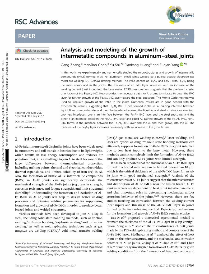
Fig. 4 shows optical images of a weld bead via the pulsed DE-GMAW-brazing method and the corresponding cross-section
Table 2 Welding parameters
Sample
Argon gas owrate of GTAWtorch (L min�1)
Argon gas owrate of GMAWtorch (L min�1)
Welding rate(m min�1)
Current dutycycle (%)
Pulse frequency(Hz)
Itotal(A)
Ibypass(A)
Imain
(A)
#1 20 5 0.5 20 80 77 0 77#2 20 5 0.5 20 80 77 22 55#3 20 5 0.5 20 80 77 32 45#4 20 5 0.5 20 80 77 55 22
Fig. 2 Schematic diagram of two-dimensional lattices used in the MCsimulation.
Fig. 3 Geometrical domain for analysis of heat conduction involved inthe joining of an ER5356 filler wire to a steel plate.
This journal is © The Royal Society of Chemistry 2017 RSC Adv., 2017, 7, 37797–37805 | 37799
Paper RSC Advances
Ope
n A
cces
s A
rtic
le. P
ublis
hed
on 0
1 A
ugus
t 201
7. D
ownl
oade
d on
14/
02/2
018
19:1
9:51
. T
his
artic
le is
lice
nsed
und
er a
Cre
ativ
e C
omm
ons
Attr
ibut
ion
3.0
Unp
orte
d L
icen
ce.
View Article Online
of the weld bead. It is evident that the Al alloy was smoothlywelded to the steel plate. The surface of the joint can beapproximated as a segment of a circle, which supports theschematic diagram shown in Fig. 3.
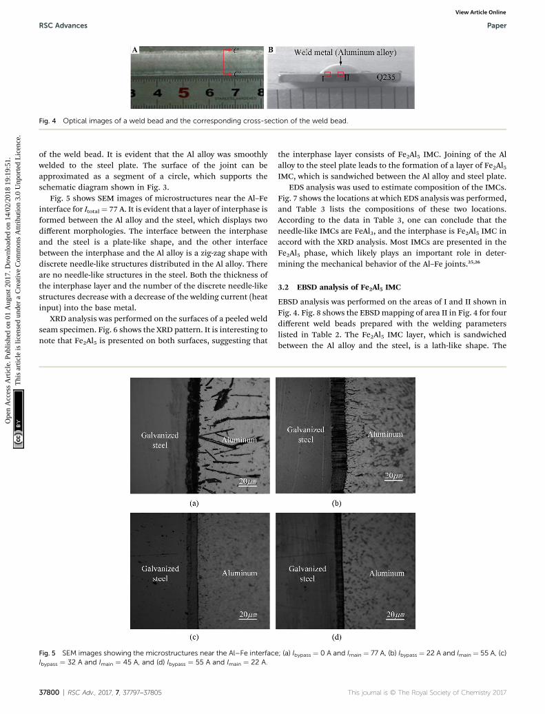
Fig. 5 shows SEM images of microstructures near the Al–Feinterface for Itotal¼ 77 A. It is evident that a layer of interphase isformed between the Al alloy and the steel, which displays twodifferent morphologies. The interface between the interphaseand the steel is a plate-like shape, and the other interfacebetween the interphase and the Al alloy is a zig-zag shape withdiscrete needle-like structures distributed in the Al alloy. Thereare no needle-like structures in the steel. Both the thickness ofthe interphase layer and the number of the discrete needle-likestructures decrease with a decrease of the welding current (heatinput) into the base metal.
XRD analysis was performed on the surfaces of a peeled weldseam specimen. Fig. 6 shows the XRD pattern. It is interesting tonote that Fe2Al5 is presented on both surfaces, suggesting that
the interphase layer consists of Fe2Al5 IMC. Joining of the Alalloy to the steel plate leads to the formation of a layer of Fe2Al5IMC, which is sandwiched between the Al alloy and steel plate.
EDS analysis was used to estimate composition of the IMCs.Fig. 7 shows the locations at which EDS analysis was performed,and Table 3 lists the compositions of these two locations.According to the data in Table 3, one can conclude that theneedle-like IMCs are FeAl3, and the interphase is Fe2Al5 IMC inaccord with the XRD analysis. Most IMCs are presented in theFe2Al5 phase, which likely plays an important role in deter-mining the mechanical behavior of the Al–Fe joints.25,26
3.2 EBSD analysis of Fe2Al5 IMC
EBSD analysis was performed on the areas of I and II shown inFig. 4. Fig. 8 shows the EBSDmapping of area II in Fig. 4 for fourdifferent weld beads prepared with the welding parameterslisted in Table 2. The Fe2Al5 IMC layer, which is sandwichedbetween the Al alloy and the steel, is a lath-like shape. The
Fig. 4 Optical images of a weld bead and the corresponding cross-section of the weld bead.
Fig. 5 SEM images showing the microstructures near the Al–Fe interface; (a) Ibypass ¼ 0 A and Imain ¼ 77 A, (b) Ibypass ¼ 22 A and Imain ¼ 55 A, (c)Ibypass ¼ 32 A and Imain ¼ 45 A, and (d) Ibypass ¼ 55 A and Imain ¼ 22 A.
37800 | RSC Adv., 2017, 7, 37797–37805 This journal is © The Royal Society of Chemistry 2017
RSC Advances Paper
Ope
n A
cces
s A
rtic
le. P
ublis
hed
on 0
1 A
ugus
t 201
7. D
ownl
oade
d on
14/
02/2
018
19:1
9:51
. T
his
artic
le is
lice
nsed
und
er a
Cre
ativ
e C
omm
ons
Attr
ibut
ion
3.0
Unp
orte
d L
icen
ce.
View Article Online

growth direction of the Fe2Al5 IMC layer is perpendicular to theinterface between the Al alloy and the steel before joining.Preferred crystal orientation for growth is the normal directionof the (001) plane, i.e., the growth direction of the Fe2Al5 IMCformed in the pulsed DE-GMAW joining is the same as thedirection of c-axis of the Fe2Al5 IMC.27 Both the size of the Fe2Al5IMC and thickness of the IMC layer increased with an increaseof the welding current (heat input) into the base metal, and theFe2Al5 IMC is orderly distributed between the Al alloy and thesteel (Fig. 8a). Such behavior is likely due to the large weldingcurrent (heat input) that causes the steel to melt and acceleratesdiffusion of Fe into the molten Al to form a large amount ofFe2Al5 IMC. From Fig. 8, one can note that the morphology ofthe Fe2Al5 IMC becomes relatively more random and disor-dered, and the orientation of the Fe2Al5 IMC deviates from thenormal direction of the (001) plane (Fig. 8d).
Fig. 9 shows EBSD mapping of area I in Fig. 4 for fourdifferent weld beads prepared with the welding parameterslisted in Table 2. The Fe2Al5 IMCs are presented in smallishlath-like shapes, and distributed more randomly than in area IIfor the same welding conditions. This trend is likely due toa lower temperature near the edge of the weld bead. Increasing
Fig. 6 XRD pattern of the surfaces of a peeled weld seam specimen.
Fig. 7 SEM image showing the locations for the EDS analysis.
Table 3 Chemical compositions of the spots of A and B in Fig. 7
Location
wt% at%
Fe Al Fe Al
A 39.97 56.00 23.94 69.42B 23.72 68.97 32.72 76.54
Fig. 8 EBSD mapping of area II in Fig. 4 for four different weld beadsprepared with the welding parameters listed in Table 2 (Itotal ¼ 77 A, (A)image of crystal orientation, (B) pole figure, (C and D) EBSD color,black-white images of the joint); (a) Ibypass ¼ 0 A and Imain ¼ 77 A, (b)Ibypass ¼ 22 A and Imain ¼ 55 A, (c) Ibypass ¼ 32 A and Imain ¼ 45 A, and (d)Ibypass ¼ 55 A and Imain ¼ 22 A.
This journal is © The Royal Society of Chemistry 2017 RSC Adv., 2017, 7, 37797–37805 | 37801
Paper RSC Advances
Ope
n A
cces
s A
rtic
le. P
ublis
hed
on 0
1 A
ugus
t 201
7. D
ownl
oade
d on
14/
02/2
018
19:1
9:51
. T
his
artic
le is
lice
nsed
und
er a
Cre
ativ
e C
omm
ons
Attr
ibut
ion
3.0
Unp
orte
d L
icen
ce.
View Article Online
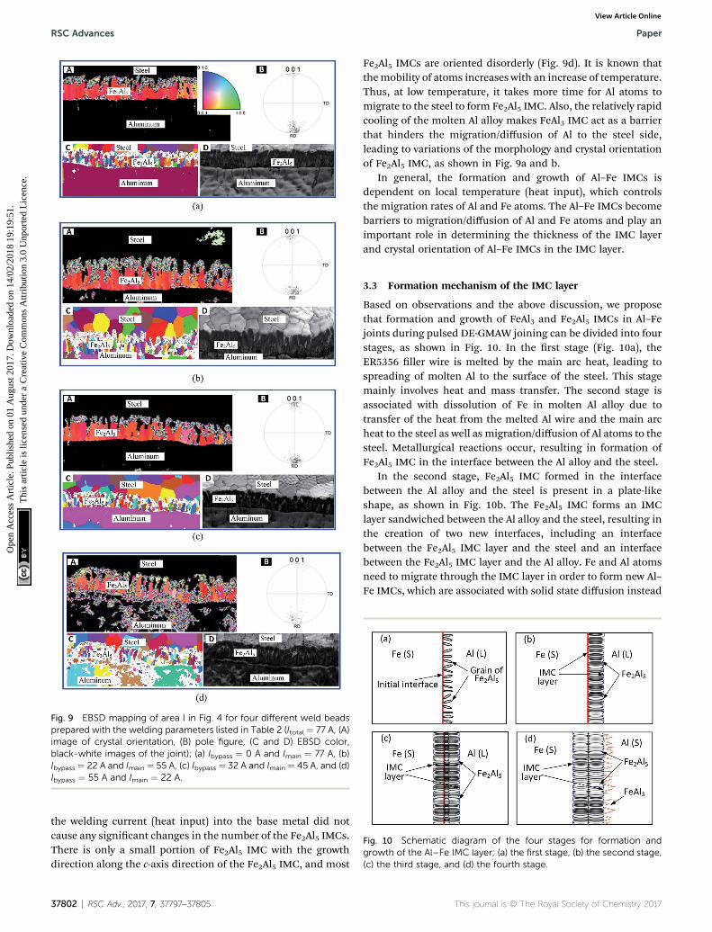
the welding current (heat input) into the base metal did notcause any signicant changes in the number of the Fe2Al5 IMCs.There is only a small portion of Fe2Al5 IMC with the growthdirection along the c-axis direction of the Fe2Al5 IMC, and most
Fe2Al5 IMCs are oriented disorderly (Fig. 9d). It is known thatthemobility of atoms increases with an increase of temperature.Thus, at low temperature, it takes more time for Al atoms tomigrate to the steel to form Fe2Al5 IMC. Also, the relatively rapidcooling of the molten Al alloy makes FeAl3 IMC act as a barrierthat hinders the migration/diffusion of Al to the steel side,leading to variations of the morphology and crystal orientationof Fe2Al5 IMC, as shown in Fig. 9a and b.
In general, the formation and growth of Al–Fe IMCs isdependent on local temperature (heat input), which controlsthe migration rates of Al and Fe atoms. The Al–Fe IMCs becomebarriers to migration/diffusion of Al and Fe atoms and play animportant role in determining the thickness of the IMC layerand crystal orientation of Al–Fe IMCs in the IMC layer.
3.3 Formation mechanism of the IMC layer
Based on observations and the above discussion, we proposethat formation and growth of FeAl3 and Fe2Al5 IMCs in Al–Fejoints during pulsed DE-GMAW joining can be divided into fourstages, as shown in Fig. 10. In the rst stage (Fig. 10a), theER5356 ller wire is melted by the main arc heat, leading tospreading of molten Al to the surface of the steel. This stagemainly involves heat and mass transfer. The second stage isassociated with dissolution of Fe in molten Al alloy due totransfer of the heat from the melted Al wire and the main archeat to the steel as well as migration/diffusion of Al atoms to thesteel. Metallurgical reactions occur, resulting in formation ofFe2Al5 IMC in the interface between the Al alloy and the steel.
In the second stage, Fe2Al5 IMC formed in the interfacebetween the Al alloy and the steel is present in a plate-likeshape, as shown in Fig. 10b. The Fe2Al5 IMC forms an IMClayer sandwiched between the Al alloy and the steel, resulting inthe creation of two new interfaces, including an interfacebetween the Fe2Al5 IMC layer and the steel and an interfacebetween the Fe2Al5 IMC layer and the Al alloy. Fe and Al atomsneed to migrate through the IMC layer in order to form new Al–Fe IMCs, which are associated with solid state diffusion instead
Fig. 9 EBSD mapping of area I in Fig. 4 for four different weld beadsprepared with the welding parameters listed in Table 2 (Itotal ¼ 77 A, (A)image of crystal orientation, (B) pole figure, (C and D) EBSD color,black-white images of the joint); (a) Ibypass ¼ 0 A and Imain ¼ 77 A, (b)Ibypass ¼ 22 A and Imain ¼ 55 A, (c) Ibypass ¼ 32 A and Imain ¼ 45 A, and (d)Ibypass ¼ 55 A and Imain ¼ 22 A.
Fig. 10 Schematic diagram of the four stages for formation andgrowth of the Al–Fe IMC layer; (a) the first stage, (b) the second stage,(c) the third stage, and (d) the fourth stage.
37802 | RSC Adv., 2017, 7, 37797–37805 This journal is © The Royal Society of Chemistry 2017
RSC Advances Paper
Ope
n A
cces
s A
rtic
le. P
ublis
hed
on 0
1 A
ugus
t 201
7. D
ownl
oade
d on
14/
02/2
018
19:1
9:51
. T
his
artic
le is
lice
nsed
und
er a
Cre
ativ
e C
omm
ons
Attr
ibut
ion
3.0
Unp
orte
d L
icen
ce.
View Article Online

of solid–liquid reaction. In general, Al atoms have a higherdiffusivity in Fe2Al5 IMC than iron atoms. Growth of the Fe2Al5IMC layer is mainly controlled by the migration/diffusion of Al.This trend leads to the third stage: the formation of a largenumber of Fe2Al5 IMCs in the steel and increase in the thick-ness of the IMC layer, as shown in Fig. 10c.
With formation of the Fe2Al5 IMC layer, a limited number ofFe atoms migrate to the Al alloy. This results in formation ofFeAl3 in the Al alloy around the interface between the Fe2Al5IMC layer and the Al alloy instead of the Fe2Al5 IMC. Theanisotropic characteristics of FeAl3 lead to formation of needle-like structures, as shown in Fig. 10d. Note that the formation ofFeAl3 IMC is limited by solid-state diffusion and the decrease ofreaction temperature during solidication of the Al alloy.
3.4 Numerical simulation of the growth of Al–Fe IMCs
The MC method was used to simulate formation and growth ofthe IMC layer observed in the pulsed DE-GMAW joining of theAl alloy and steel. In the simulation, 400 � 600 quadrilateralmeshes were used, and the length of the unit lattice was 0.1 mm.Fixed boundary conditions were used on the edges of the Alalloy and steel. Sampling frequency and simulation time were 5MHz and 4 s, respectively. The parameters used in the analysiswere from He et al. work.28
Fig. 11 shows temporal variation of the IMC layer sand-wiched between Al and steel substrates at different times fora welding current of 55 A. It is evident that only Fe2Al5 IMC ispresent at the early stage, and randomly distributes near theinterface between the Al and steel. From Fig. 11a and b, notethat the nucleation and growth of Fe2Al5 IMCs occur
concurrently, resulting in the formation of equiaxed Fe2Al5IMCs with a portion of the IMCs in the Al alloy in a short timeperiod. For the growth (simulation) time being 2.8 s, FeAl3 IMCforms due to a decrease of the temperature to the melting pointof Al. This result is in accord with the experimental observationand consistent with results reported by Zhang et al.18 FromFig. 11c, one can note an increase of the Fe2Al5 IMC layer due tomigration of Al through the Fe2Al5 IMC layer to the steel, whichsupports the experimental observation.
Fig. 11d presents the nal morphology of the Al–Fe IMCswith thickness of the IMC layer being �11 mm. The Fe2Al5 IMClayer is a plate-like shape, and FeAl3 IMC discretely distributesin the Al alloy in a needle-like shape. It is important to note thatthe Fe2Al5 IMC grows towards the steel and is present ina columnar structure, similar to structures shown in Fig. 5 andthere is a preferred direction for growth of the Fe2Al5 IMC.
Fig. 12 shows numerical results of the morphologies of IMCsat a growth (simulation) time of 4 s for two different weldingcurrents (Itotal ¼ 77 A). It is evident that the thickness of theFe2Al5 IMC layer decreases with a decrease of the welding current(heat input) into the base metal in accord with the experimentalobservation (Fig. 5). Also, large welding current (heat input)promotes formation of FeAl3 IMC in the Al alloy due to Fe atomsbeing able to migrate through the Fe2Al5 IMC layer to reach theAl alloy at high temperature. To hinder formation of FeAl3 IMCand reduce thickness of the Fe2Al5 IMC layer, one needs toreduce the welding current (heat input) into the base metal.
Fig. 13a shows numerical results of variation of the thicknessof the Fe2Al5 IMC layer with simulation (growth) time. Accord-ing to Fig. 13a, growth of the Fe2Al5 IMC layer can be dividedinto three stages. The rst stage is mainly controlled by
Fig. 11 Temporal variation of the IMC layer sandwiched between Al and steel substrates (Imain ¼ 55 A, Ibypass ¼ 22 A); (a) t ¼ 0.4 s, (b) t¼ 1.2 s, (c) t¼ 2.8 s and (d) t ¼ 4 s.
This journal is © The Royal Society of Chemistry 2017 RSC Adv., 2017, 7, 37797–37805 | 37803
Paper RSC Advances
Ope
n A
cces
s A
rtic
le. P
ublis
hed
on 0
1 A
ugus
t 201
7. D
ownl
oade
d on
14/
02/2
018
19:1
9:51
. T
his
artic
le is
lice
nsed
und
er a
Cre
ativ
e C
omm
ons
Attr
ibut
ion
3.0
Unp
orte
d L
icen
ce.
View Article Online

nucleation of Fe2Al5 IMCwith a small growth rate. Following therst stage is the second stage with fast growth of the Fe2Al5 IMClayer. The growth rate of the Fe2Al5 IMC layer rst increases withan increase of simulation (growth) time, reaches the maximum,and then decreases with an increase of simulation (growth)time. In this stage, growth of the Fe2Al5 IMC is associated withdissolution of Fe in the molten Al alloy and fast migration/diffusion of Fe. In the third stage, the local temperaturedecreases due to solidication, and Al atoms migrate throughthe Fe2Al5 IMC layer, which reduces the migration rate of Al andgrowth rate of the Fe2Al5 IMC layer.
Fig. 13b shows comparison between numerical results fora simulation time of 4 s and total current of 77 A, and theexperimental results for total current of 77 A. It is evident thatthe numerical results are in good accord with the experimentalresults, which suggests that assumptions used in the numericalcalculation are reasonable. According to the results shown inFig. 13b, the thickness of the Fe2Al5 IMC layer decreases with anincrease (decrease) of the welding current (heat input) into thebypass (main) circuit. The welding current (heat input) plays animportant role in controlling growth of the Al–Fe IMCs. One canuse pulsed DE-GMAW joining to control formation and growthof Al–Fe IMCs in order to control the mechanical strength of Al–steel joints.
4. Conclusions
Intermetallic compounds play an important role in determiningthe mechanical strength of dissimilar metallic joints. Thepulsed DE-GMAW-brazing process was used in this work to joinan Al alloy to a steel plate. Formation and growth of Al–Fe IMCsin the Al–steel joints was studied experimentally and numeri-cally. Important conclusions are summarized below.
(1) Both Fe2Al5 and FeAl3 IMCs form during the joining.There is a large portion of Fe2Al5 IMC which forms an IMC layer.The thickness of the Fe2Al5 IMC layer increases with an increaseof welding current (heat input) into the base metal.
(2) EBSD analysis reveals that a distribution of morphologyand size of Fe2Al5 IMCs exist in an Al–Fe joint. With highwelding current (heat input) into the base metal, Fe2Al5 IMC ispresent in a lath-like shape with relatively orderly distribution.There is a preferred direction for growth of the Fe2Al5 IMC,which is parallel to the normal direction of the (001) plane.
(3) Formation and growth of Al–Fe IMCs can be divided intothree stages: (1) nucleation of Fe2Al5 IMC in the interface of theAl alloy and steel, (2) fast growth of the Fe2Al5 IMC layer asso-ciated with dissolution of Fe in the molten Al alloy and fastmigration/diffusion of Fe, and (3) slow growth of the Fe2Al5 IMCcontrolled by diffusion of Al atoms through the Fe2Al5 IMClayer. During solidication, FeAl3 IMC forms in the Al alloy nearthe interface between the Fe2Al5 IMC layer and Al.
(4) The MC method was used to simulate the formation andgrowth of the Al–Fe IMCs. The numerical results are in good
Fig. 12 Numerical results of the morphologies of IMCs at a growth (simulation) time of 4 s for two different welding currents: (Itotal ¼ 77 A); (a)Ibypass ¼ 22 A, Imain ¼ 55 A, and (b) Ibypass ¼ 55 A, Imain ¼ 22 A.
Fig. 13 (a) Variation of the thickness of the Fe2Al5 IMC layer witha simulation time (Imain ¼ 55 A, Ibypass ¼ 22 A), and (b) comparisonbetween numerical results (t ¼ 4 s, Itotal ¼ 77 A) and experimentalresults (Itotal ¼ 77 A).
37804 | RSC Adv., 2017, 7, 37797–37805 This journal is © The Royal Society of Chemistry 2017
RSC Advances Paper
Ope
n A
cces
s A
rtic
le. P
ublis
hed
on 0
1 A
ugus
t 201
7. D
ownl
oade
d on
14/
02/2
018
19:1
9:51
. T
his
artic
le is
lice
nsed
und
er a
Cre
ativ
e C
omm
ons
Attr
ibut
ion
3.0
Unp
orte
d L
icen
ce.
View Article Online

accord with the experimental results, and support proposedmechanisms for formation and growth of Al–Fe IMCs in Al–Fejoints. The thickness of the Fe2Al5 IMC layer increases non-linearly with an increase of the simulation (growth) time.
Acknowledgements
This work is funded by the National Natural Science Foundationof China [Grant No: 61365011, 2014; Grant No: 51675256, 2016].
References
1 G. Pardal, S. Meco, S. Ganguly, S. Williams and P. Prangnell,Int. J. Adv. Manuf. Tech., 2014, 73, 365–373.
2 R. Taban, J. E. Gould and J. C. Lippold,Mater. Des., 2010, 31,2305–2311.
3 H. Das, S. Basak, G. Das and T. K. Pal, Int. J. Adv. Manuf.Tech., 2013, 64, 1653–1661.
4 D. Travessa, M. Ferrante and G. Ouden, Mater. Sci. Eng., A,2002, 337, 287–296.
5 M. Acarer and B. Demir, Mater. Lett., 2008, 62, 4158–4160.6 J. Tsujino, T. Ueoka, T. Kashino and F. Sugahara, Jpn. J. Appl.Phys., 1999, 38, 4254–4255.
7 R. Borrisutthekul, P. Mitsomwang, S. Rattanachan andY. Mutoh, Energ. Res. J., 2010, 1, 82–88.
8 R. Cao, G. Yu, J. H. Chen and P. C. Wang, J. Mater. Process.Technol., 2013, 213, 1753–1763.
9 Y. C. Su, X. M. Hua and Y. X. Wu, Mater. Sci. Eng., A, 2013,578, 340–345.
10 M. Sonia, G. Supriyo, W. Stewar and M. Norman, J. Mater.Eng. Perform., 2014, 23, 3361–3370.
11 G. L. Qin, Z. Lei, B. L. Su and X. M. Meng, J. Mater. Process.Technol., 2014, 214, 2684–2692.
12 S. Yang, J. Zhang, J. Lian and Y. Lei, Mater. Des., 2013, 49,602–612.
13 S. Niu, S. Chen, H. G. Dong and D. S. Zhao, J. Mater. Eng.Perform., 2016, 25, 1839–1847.
14 Y. Shi, J. Li, G. Zhang, J. K. Huang and Y. F. Gu, J. Mater. Eng.Perform., 2016, 25, 1916–1923.
15 A. Das, M. Shome, S. F. Goecke and A. De, Sci. Technol. Weld.Joining, 2016, 21, 303–309.
16 J. L. Song, S. B. Lin, C. L. Yang and G. C. Ma,Mater. Sci. Eng.,A, 2009, 509, 31–40.
17 S. Madhavan, M. Kamaraj, L. Vijayaraghavan and K. S. Rao,Trans. Indian Inst. Met., 2016, 1–8.
18 H. T. Zhang, J. C. Feng and P. He, Mater. Sci. Technol., 2008,24, 1346–1349.
19 L. Shao, Y. Shi, J. K. Huang and S. J. Wu, Mater. Des., 2015,66, 453–458.
20 M. J. Chen, J. K. Huang, C. C. He, Y. Shi and D. Fan, ActaMetall. Sin., 2016, 52, 113–119.
21 Y. Shi, G. Zhang, Y. Huang, L. H. Lu, J. K. Huang and Y. Shao,Weld. J., 2014, 93, 216-s–224-s.
22 Y. Shi, R. H. Han, J. K. Huang and Y. Shao, J. Manuf. Sci. Eng.,2014, 136, 024502.
23 Y. Shi, R. H. Han, J. K. Huang and D. Fan, Acta Phys. Sin.,2012, 61, 020205.
24 Y. Shi, M. J. Chen, J. K. Huang, Y. F. Gu and D. Fan, Int. J.Mod. Phys. B, 2016, 30, 1650014–1650022.
25 H. Springer, A. Kostka, E. J. Payton, D. Raabe, A. Kaysser-Pyzalla and G. Eggeler, Acta Mater., 2011, 59, 1586–1600.
26 J. J. Zhang, W. Liang and H. T. Li, RSC Adv., 2015, 127,104954–104959.
27 U. Burkhardt, Y. Grin and M. Ellner, Acta Crystallogr., Sect. B:Struct. Sci., 1994, 50, 313–316.
28 C. C. He, J. K. Huang, Y. Shi and D. Fan, J. Jilin Univ., 2014,44, 1037–1041.
This journal is © The Royal Society of Chemistry 2017 RSC Adv., 2017, 7, 37797–37805 | 37805
Paper RSC Advances
Ope
n A
cces
s A
rtic
le. P
ublis
hed
on 0
1 A
ugus
t 201
7. D
ownl
oade
d on
14/
02/2
018
19:1
9:51
. T
his
artic
le is
lice
nsed
und
er a
Cre
ativ
e C
omm
ons
Attr
ibut
ion
3.0
Unp
orte
d L
icen
ce.
View Article Online