Embed Size (px)
Citation preview

MASARYK UNIVERSITY
FACULTY OF INFORMATICS
}w���������� ������������� !"#$%&'()+,-./012345<yA|Analysis and detection of
Skype network traffic
DIPLOMA THESIS
Lubos Ptacek
Brno, spring 2011

Declaration
I declare that this thesis is my own work and has not been submitted in anyform for another degree or diploma at any university or other institution oftertiary education. Information derived from the published or unpublishedwork of others has been acknowledged in the text and a list of references isgiven.
Advisor: RNDr. Jan Vykopal
ii

Acknowledgement
I would like to express my gratitude to RNDr. Jan Vykopal for supervisingmy work and thank Jan Hapala for advices.
iii

Abstract
This thesis deals with traffic identification of the Skype application. Payloadbased analysis of the standby traffic and voice calls is done. Basic Skypeflow patterns are used to create a plugin for NfSen to display potential voicecalls in the network.
iv

Keywords
Skype, voice calls, traffic, payload, analysis, NetFlow, NfSen
v

Contents
1 Introduction . . . . . . . . . . . . . . . . . . . . . . . . . . . . . . . 22 Skype history . . . . . . . . . . . . . . . . . . . . . . . . . . . . . . 33 Skype . . . . . . . . . . . . . . . . . . . . . . . . . . . . . . . . . . . 4
3.1 Skype entities . . . . . . . . . . . . . . . . . . . . . . . . . . . 43.2 Key components . . . . . . . . . . . . . . . . . . . . . . . . . . 6
3.2.1 Ports . . . . . . . . . . . . . . . . . . . . . . . . . . . . 63.2.2 Host cache . . . . . . . . . . . . . . . . . . . . . . . . . 63.2.3 Encryption . . . . . . . . . . . . . . . . . . . . . . . . . 7
3.3 Stages in Skype network conversation . . . . . . . . . . . . . 73.3.1 Startup and UDP probing . . . . . . . . . . . . . . . . 73.3.2 TCP handshake with supernode . . . . . . . . . . . . 93.3.3 Authentication . . . . . . . . . . . . . . . . . . . . . . 113.3.4 Skype latest version check . . . . . . . . . . . . . . . . 113.3.5 NAT and firewall determination . . . . . . . . . . . . 123.3.6 Going online . . . . . . . . . . . . . . . . . . . . . . . 123.3.7 Going offline . . . . . . . . . . . . . . . . . . . . . . . 163.3.8 Voice codec . . . . . . . . . . . . . . . . . . . . . . . . 163.3.9 Call placement . . . . . . . . . . . . . . . . . . . . . . 17
4 NetFlow protocol . . . . . . . . . . . . . . . . . . . . . . . . . . . . 214.1 NfSen and NFDUMP . . . . . . . . . . . . . . . . . . . . . . . 23
4.1.1 NFDUMP . . . . . . . . . . . . . . . . . . . . . . . . . 234.1.2 NfSen . . . . . . . . . . . . . . . . . . . . . . . . . . . 264.1.3 Plugins for NfSen . . . . . . . . . . . . . . . . . . . . . 26
5 Creation of DetectSkype plugin for NfSen . . . . . . . . . . . . . 285.1 Backend plugin . . . . . . . . . . . . . . . . . . . . . . . . . . 285.2 Frontend plugin . . . . . . . . . . . . . . . . . . . . . . . . . . 31
6 Conclusion . . . . . . . . . . . . . . . . . . . . . . . . . . . . . . . . 36
1
Chapter 1
Introduction
Skype [20, 24] is a software application that allows users to make voice andvideo calls and to chat over the Internet. Unregulated Skype usage by em-ployees for leisure and private purposes can lead to economic loss. Skypecan often circumvent network restrictions like NAT and firewall by travers-ing them. Therefore enterprises are seeking solutions to regulate Skype ac-tivities over their networks. Skype establishes many concurrent connec-tions in a rapid manner, which can be recognized as undesirable behaviour.Skype traffic detection can be categorized into payload-oriented and intononpayload-oriented approaches.
On the other hand, success of the application comes from user friendlyoperation, it can operate without manual user configuration. This user friend-liness is largely due to ability to detect the current network configurationand use of mechanisms to circumvent many applied network restrictions.
2
Chapter 2
Skype history
Skype was founded in 2003 by Niklas Zennstrom from Sweden and JanusFriis from Denmark. The Skype software was developed by Estonians AhtiHeinla, Priit Kasesalu and Jaan Tallinn [13], who were also behind the peer-to-peer file sharing software Kazaa [22]. In April 2003, Skype.com andSkype.net domain names were registered. In August 2003, the first publicbeta version was released.
One of the initial names for the project was “Sky peer-to-peer”, whichwas then abbreviated to “Skyper”. However, some of the domain namesassociated with “Skyper” were already taken. Dropping the final letter leftthe current title “Skype”, for which domain names were available. Callsto other users within the Skype service are free, while calls to both tradi-tional landline telephones and mobile phones can be made for a fee using adebit-based user account system. Skype has also become popular for its ad-ditional features which include instant messaging, file transfer, and videoconferencing. Skype has 663 million registered users as of 2010 [15]. The av-erage number of users connected each month was 145 million in the fourthquarter of 2010, versus 105 million a year earlier, while paying customersrose over the same period to an average 8.8 million per month, from 7.3 mil-lion. Skype reached a record with 30 million simultaneous online users on28 March 2011 [14]. The network is operated by Microsoft Skype Division,which has its headquarters in Luxembourg. Most of the development team[13] and 44% of the overall employees of Skype are situated in the offices ofTallinn and Tartu, Estonia. eBay acquired Skype Limited in September 2005and in April 2009 announced plans to spin it off through an initial publicoffering in 2010. It was acquired by Silver Lake Partners in 2009. Microsoftagreed to purchase Skype for $8.5 billion on May 2011 and the company isto be incorporated as a division of Microsoft called Microsoft Skype Divi-sion.
Some network administrators have banned Skype on corporate, govern-ment, home, and education networks, citing reasons such as inappropriateusage of resources, excessive bandwidth usage and security concerns.
3

Chapter 3
Skype
3.1 Skype entities
According to [10], we can distinguish some entities in the communicationframework.
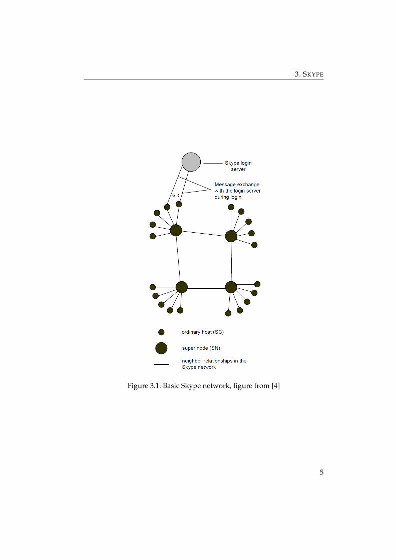
Skype client (SC) End client which places voice calls. Each SC maintainsa record host cache which contains IP addresses and port numbers of su-per nodes. Notation SCA and SCB denotes the SC of the Caller and Calleerespectively.
Supernode (SN) Online nodes that maintain the skype overlaying net-work. As described in [7], a supernode performs routing tasks such as for-warding requests to appropriate destinations and answer to queries fromother SCs or SNs. A supernode can also forward login requests in case thelogin server is not directly reachable from a SC. Any SC with a public IPaddress can be promoted to an SN without the awareness of the SC host.This behaviour can be switched off by changing the registry entries.
Skype HTTP Server (HS) The HTTP server of ui.skype.com.
Login server (LS) An SN that Skype uses to provide authentication ser-vices to SCs.
Neighbour supernode (NSN) SNs that are logically near to an SC. An SCmust establish connection to some SNs for Skype communications. The SClocates and then binds to its NSN for such purpose. An SN can be the NSNof multiple SCs simultaneously.
4
3. SKYPE
Figure 3.1: Basic Skype network, figure from [4]
5

3. SKYPE
3.2 Key components
I have performed traffic analysis and network measurements for the Win-dows Skype versions 4.1.0.136, 4.2.0.187 and 5.3.0.111 unless otherwise stated.
3.2.1 Ports
Skype uses UDP and TCP protocols for communication. SC has normallythree listening ports enabled. They are configured in the Connection dialogbox. The first one is randomly chosen during the application installationand is higher then 1024 according to [16]. Then there are open listeningports 80 and 443 which can be disabled in the dialog box. SC is reachableby the first port number for UDP and incoming TCP traffic. For TCP con-nection, Skype tries to contact other hosts at ports higher than 1024. If thereare network restrictions applied, it tries again to this host on port 443. If thisattempt fails, it will try on port 80. I have seldom observed connection onport 80. The reason could be that SC tries concurrently to initiate connec-tion with other hosts and there will be a successful connection earlier thanthe need of making an attempt on port 80. So the ports 443 and 80 serve asa fallback precaution.
3.2.2 Host cache
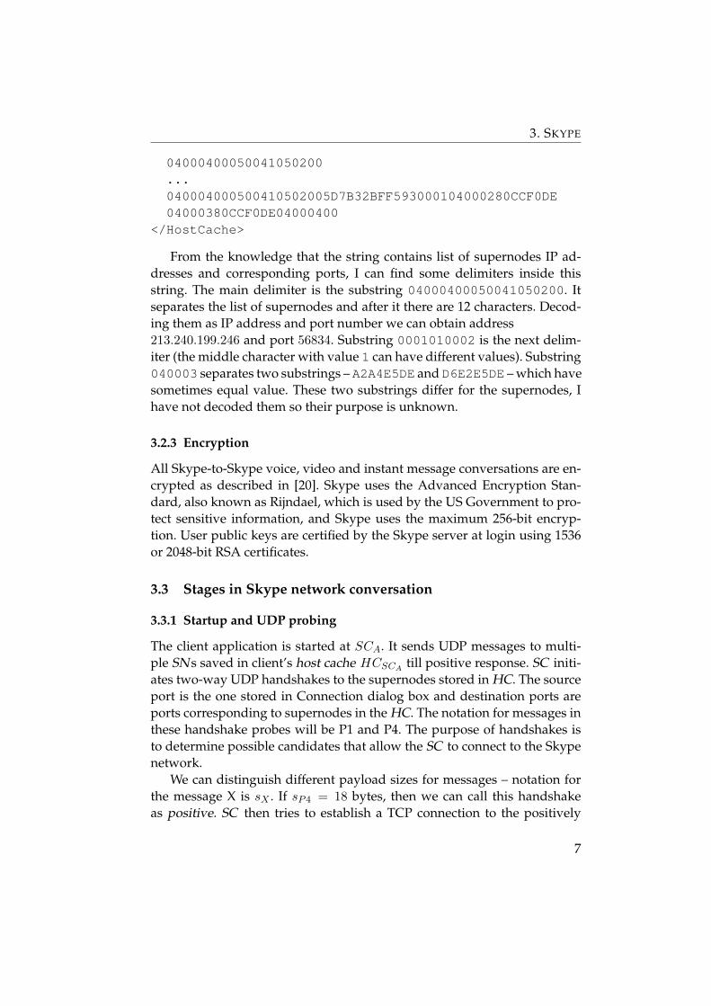
Skype network is an overlay network and thus each SC maintains a ta-ble of reachable supernodes. It is called host cache (HC) and is stored ina XML file “shared.xml” (for Windows 7 in C:\Users\<user name>\AppData\Roaming\Skype\). The HC contains a maximum of 200 entries.The file shared.xml contains element <HostCache> with a hex string(<HostCache> with 200 entries has around 12800 characters). An exampleof the <HostCache> element follows.
<HostCache>41C80105004105020059A9FF2F9DC20001040002DCCDF0DE040003DCCDF0DE04000400050041050200...04000400050041050200D5F0C7F6DE020001010002A2A4E5DE040003D6E2E5DE
6
3. SKYPE
04000400050041050200...040004000500410502005D7B32BFF593000104000280CCF0DE04000380CCF0DE04000400
</HostCache>
From the knowledge that the string contains list of supernodes IP ad-dresses and corresponding ports, I can find some delimiters inside thisstring. The main delimiter is the substring 04000400050041050200. Itseparates the list of supernodes and after it there are 12 characters. Decod-ing them as IP address and port number we can obtain address213.240.199.246 and port 56834. Substring 0001010002 is the next delim-iter (the middle character with value 1 can have different values). Substring040003 separates two substrings – A2A4E5DE and D6E2E5DE – which havesometimes equal value. These two substrings differ for the supernodes, Ihave not decoded them so their purpose is unknown.
3.2.3 Encryption
All Skype-to-Skype voice, video and instant message conversations are en-crypted as described in [20]. Skype uses the Advanced Encryption Stan-dard, also known as Rijndael, which is used by the US Government to pro-tect sensitive information, and Skype uses the maximum 256-bit encryp-tion. User public keys are certified by the Skype server at login using 1536or 2048-bit RSA certificates.
3.3 Stages in Skype network conversation
3.3.1 Startup and UDP probing
The client application is started at SCA. It sends UDP messages to multi-ple SNs saved in client’s host cache HCSCA
till positive response. SC initi-ates two-way UDP handshakes to the supernodes stored in HC. The sourceport is the one stored in Connection dialog box and destination ports areports corresponding to supernodes in the HC. The notation for messages inthese handshake probes will be P1 and P4. The purpose of handshakes isto determine possible candidates that allow the SC to connect to the Skypenetwork.
We can distinguish different payload sizes for messages – notation forthe message X is sX . If sP4 = 18 bytes, then we can call this handshakeas positive. SC then tries to establish a TCP connection to the positively
7

3. SKYPE
probed supernode. If sP4 = 51 or 53, then we can call this handshake asnegative. No TCP connection will be initiated between Skype client andsupernode. This UDP probing continues in rapid and continuous manneruntil positive is present.
Sometimes we can observe handshakes consisting of 4 messages P1, P2,P3 and P4 at the start of the application. It holds for the message sizes thatsP2 = 11 bytes, sP3 = sP1 + 5. Analysing the payload of the messages wecan differentiate some byte sequences according to [7] – session identifiers,function parameters, IP address exchange.
Session identifiers P1 is a initiating message so the first two bytes formsthe session identifier. The important observation is that the session iden-tifier is equal for P2 and P3 too but not for P4. In fact, this identifier is anumber that is increased by two on every new request.
Function parameter The third byte of UDP messages has particular val-ues so we can consider it as some kind of function parameter. It holds thatit contains value 0x02 for P1 and P4. The value is different for P2 and P3 butthe lower nibble is always the same (a nibble is an aggregation of four bitsso there are two nibbles in a byte – the higher one and the lower one). It is0x7 for P2 and 0x3 for P3. It should be mentioned that for data packets likevoice packets the lower nibble equals to 0xd. There is one more value thatis the same through the P3 payloads. The fourth byte possesses 0x01 value.
IP address exchange We can distinguish four four-byte sequences in themessages. Notation for the payload bytes x to y for the message X is Xx−y.P24−7 contains IP address of the SC, P39−12 contains IP address of the su-pernode. The SC ’s IP address in this message is never private address. It isthe publicly visible IP address created by the NAT closest to the supernode.This is called a reflexive transport address according to [9]. Then sequencesthat are not IP addresses can be observed. I assume them as some uniquemessage identifiers: P18−11 = P313−16 and P28−11 = P35−8.
Byte sequences are depicted in the following tables. SC1–SC4 is SC ’s IPaddress, N1–N4 SN ’s IP address.
P1 SI SI 02 xxxxxxxx A1A2A3A4 xxxx . . .
P2 SI SI x7 SC1 SC2 SC3 SC4 B1B2B3B4
8

3. SKYPE
P3 SI SI x3 01 B1B2B3B4 N1N2N3N4 A1A2A3A4 . . .
P4 xxxx 02 xx . . .
We can refer to a full UDP probe if P1, P2, P3 and P4 messages arepresent and to a partial UDP probe if only P1 and P4 messages are present.As we can detect particular IP addresses in the full UDP probes we can con-sider these probes as some part of NAT detection algorithm which operatessimilar to STUN (Session Traversal Utilities for NAT) [9].
The SC continues in the partial UDP probing even after it has beenlogged into the Skype network.
3.3.2 TCP handshake with supernode
In this step Caller registers to Skype network. A TCP request is sent to thepositively responding supernode from the previous step. The TCP connec-tion is established to the same port the UDP probe used.
TCP problems If there is a problem with establishing a connection to thepositively UDP probed supernode, then Skype will start initiating connec-tion over ports 443 and 80. The tricky thing is that Skype does not followcommunication protocols associated with these well-known ports. Skypeemploys some modification of TLS protocol [2] for port 443 as describedfurther.
Port 443 It holds for the first message M1 sent to the supernode thatsM1 = 72 bytes. The main observation is that the message payload startswith 56 byte sequence:
80 46 01 03 01 00 2d 00
00 00 10 00 00 05 00 00
04 00 00 0a 00 00 09 00
00 64 00 00 62 00 00 08
00 00 03 00 00 06 01 00
80 07 00 c0 03 00 80 06
00 40 02 00 80 04 00 80
Using Wireshark to view details of captured network traffic I can decodethis sequence as follows. It is TLS 1.0 Client Hello message in SSLv2record layer.
9

3. SKYPE
Values {80 46}mean the length of the message (that is 70), {01} hand-shake message type (here Client Hello), {03 01} the version of the TLSprotocol by which the client wishes to communicate during this session(here TLS 1.0), {00 2d} cipher specification length (here 45), {00 00} ses-sion ID length (here 0), {00 10} challenge length (here 16), {00 00 05 0000 04 00 00 0a 00 00 09 00 00 64 00 00 62 00 00 08 00 0003 00 00 06 01 00 80 07 00 c0 03 00 80 06 00 40 02 00 8004 00 80} list of the cryptographic options supported by the client. R1messages differ only in the last 16 bytes and it should represent thechallenge attribute.
Response message R2 from the supernode contains always at the first 79bytes these values:
16 03 01 00 4a 02 00 00
46 03 01 40 1b e4 86 02
ad e0 29 e1 77 74 e5 44
b9 c9 9c b4 31 31 5e 02
dd 77 9d 15 4a 96 09 ba
5d a8 70 20 1c a0 e4 f6
4c 63 51 ae 2f 8e 4e e1
e6 76 6a 0a 88 d5 d8 c5
5c ae 98 c5 e4 81 f2 2a
69 bf 90 58 00 05 00
This start of the message is similar to to the TLS Server Hello. Value{16}means content type (here handshake), {03 01}means TLS 1.0, {004a} means length (here 74), {02} handshake type (here Server Hello),{00 00 46} length (here 70), {03 01}means TLS 1.0.
Bytes R212−15 should be gmt unix time. In the TLS protocol descrip-tion is gmt unix time “the current time and date in standard UNIX 32-bitformat (seconds since the midnight starting Jan 1, 1970, GMT)”. But theR212−15 bytes have fixed value {40 1b e4 86} and that is “Jan 31, 200418:23:18 Central Europe Standard Time”.
Then there are 28 bytes in the random bytes field, one byte of sessionID length, 32 bytes of session ID. Field with bytes R277−78 has thevalue 00 05 and according to TLS it should be “the single cipher suite se-lected by the server from the list in Client Hello” – here it isTLS RSA WITH RC4 128 SHA.
10

3. SKYPE
Port 80 In Skype version 2.0 there were noticed value recurrences in thehigher nibbles of the R1 message as mentioned in [7]. I have not recordedthese recurrences or any other in the messages to the port 80 in Skype ver-sions 4.1 and 4.2.
3.3.3 Authentication
After connection to some supernode with destination port 33033, SC tries toauthenticate itself to the Skype network. In previous versions of the Skypeapplication there were four TCP messages exchanged in every connectionto LS in general and after that the connection is closed as mentioned in [7].I have measured payload pattern independently in all tested Skype ver-sions but only in communication with particular LSs like LS with IP ad-dress 195.46.253.219. My assumption is that the pattern depends onparticular login server or some condition. When the pattern occurs then thefirst six messages M1-M6 exchanged between SC and LS look like depictedfurther.
M1 SC → LS 16 03 01 00 00
M2 SC ← LC 17 03 01 00 00
M3 SC → LS 16 03 01 00 00
M4 SC ← LS 17 03 01 00 00
M5 SC → LS 16 03 01 00xx 42 cd ef e7 40 d7 2f 1d . . .
M6 SC ← LS 17 03 01 01 . . .
Messages M1-M4 have fixed size of 5 bytes as opposite to M5 and M6.The fourth byte of the message M6 does not contain a fixed value. Thisholds for the connections on ports 443 and 80 too.
3.3.4 Skype latest version check
When the client is first installed, it sends an HTTP request to ui.skype.com.The request method is GET and we can find in the request URI followingpatterns: /ui/ and /installed.
If Skype has already been installed, it will check with HS the latest ver-sion of the application. This check occurs every time Skype is started. Skypeclient sends an HTTP request and the patterns are /ui/ and/getlatestversion?ver=.
11

3. SKYPE
/ui/0/5.3.0.111./en/installed?info=google-toolbar:notoffered;ienotdefaultbrowser2,google-chrome:notoffered;alreadyoffered
Table 3.1: Example of the GET request after Skype installation
/ui/0/5.3.0.111./en/getlatestversion?ver=5.3.0.111&uhash=1d1bb29ea1f2970757800d8e22b9ce8d6&google-chrome:notoffered;alreadyoffered
Table 3.2: Example of the GET request after Skype start
I have captured this GET request regularly every 4 hours and further-more requests with the empty request URI can occur more often.
3.3.5 NAT and firewall determination
At the transport layer, Skype is performing NAT and firewall detection.NAT traversal is an important function of Skype for determining what kindof NAT settings is the SC currently behind. Once determined, the clientstores this kind of information in the “shared.xml” file. Each SC uses a vari-ant of the STUN protocol to determine the type of NAT the client is behind.There is no global NAT and firewall traversal server. If there was one, theSC would have exchanged traffic with it at the start, but no IP address rep-etition or some specific behaviour at particular stages of the Skype sessionwas observed.
3.3.6 Going online
If the client starts only with the Offline status, no further traffic is recorded.Going Online, UDP packets are sent to multiple SNs rapidly and contin-uously. This kind of UDP pinging messages is detected during the wholeSkype session. In this step, SC searches for available NSN and binds to itwith TCP connection.
After positive UDP handshake with some SN as described previously,SC initiates a TCP connection to this node. If the connection is success-ful, then SC and SN exchange messages. If the connection is kept, then SNbecomes neighbour supernode for the Skype client. This binding lasts aslong as the SC is online but sometimes termination of the connection can
12

3. SKYPE
Figure 3.2: At least every 120 seconds SC sends TCP packet to its NSN.
occur (e.g. I have measured one 39 hours long connection till terminationoccured). My prediction is that it is caused by unavailability of the NSNor the supernode becomes a regular node. As the SC is always bind withsome NSN, a new binding process starts in the same way as before. I didnot find any particular pattern that would be common for every startup ofSC. However, there can be often observed packets with payload sizes 8, 27(or 28), 4 bytes initiated by SC between first 10 packets exchanged betweenSC and NSN.
There is probably some timeout counter used on the both sides as we canfind regular traffic. I have found out that if any of the parties sends packetscontaining some signalling information in the 120 seconds time window,then SC or NSN sends a packet with s = 2 and begins a sequence of mes-sages M1–M4. They can be some keep-alive messages. Timeouts start tocount down for corresponding parties from the moment when M1 and M2
are sent.M1 → sM1 = 2 TCPPush,Ackflags
M2 ← sM2 = 0 TCPAckflag
M3 ← sM3 = 2 TCPPush,Ackflags
M4 → sM4 = 0 TCPAckflag
Periodicity in sending packets is shown in Figure 3.2. I have capturedalmost 135 hours of standby Skype traffic with the longest continuouslymeasured time slot of 67 hours. I have counted up inter packet time gapsfor outgoing packets in one minute time slots and that has exposed peaks of120 seconds almost every two minutes so it holds true. Moreover, it holdsfor the standby mode that for most outgoing packets with payload greaterthan 200 bytes the inter packet time gap equals to 15 minutes, Figure 3.3.
13

3. SKYPE
Figure 3.3: Inter packet gap of 900 seconds (i.e. 15 minutes) for outgoingTCP packets to NSN is observed every 15 minutes.
This was confirmed only for Skype versions 4.0 and 4.2.From my measurements, SC also establishes in average 5 short TCP con-
nections per hour. UDP probing as checking available peers in the Skypenetwork occurs mainly in bursts. In average, 30 new peers are probed ev-ery hour (approximately 1900 per 67 hours) as shown in Figure 3.4, whichshows us statistics for the 67 hours lasting Skype standby mode. The mostpeers are probed at the start of the application as we can see. Every peeris characterized by its ID so if a new peer is probed, then it gains his IDand corresponding dot is plotted to the graph. If some peer sends UDPpacket to the SC, then corresponding ID is plotted on the negative y-axis.Lot of peers are probed repetitively. Very interesting is that sometimes theSC sends UDP packets repetitively (e.g. 700 packets per 50 hours) even tothe peers that have never responded.
Perl modul Geo::IPfree was used to determine the originating countriesof the probed peers, Figure 3.5. The modul uses a local file-based databaseto provide basic geolocation services. Countries were aggregated to con-tinents if their country codes are not presented. Most contacted peers arelocated in the United States.
If UDP protocol is restricted, SC utilizes TCP protocol for TCP probesbut not in bursts like in UDP case and in lesser scope. Positively probedsupernode becomes SC’s NSN. TCP packets are exchanged continuouslybetween SC and NSN with average packet rate 1 per 10 seconds.
14

3. SKYPE
Figure 3.4: Each dot represents packet sent in a given time by SC to someother Skype peer whose corresponding ID is represented on the y-axis. Pos-itive ID is for packet from SC to the peer, negative ID for packet to SC.
Figure 3.5: Country statistics for contacted peers.
15

3. SKYPE
Figure 3.6: The average network bit rate for corresponding audio band-widths, figure from [19]
3.3.7 Going offline
When the client is switched to Offline status, every open TCP connectionis finished. TCP connection with the NSN is always ended. After sign outfrom the Skype application, TCP connection with address like78.141.181.242 or 213.146.188.16 is established. These connectionsoccur sometimes after startup of the SC too. These addresses are associatedwith Skype Communications according to WHOIS database. I suppose thatthis connection can be somehow important for creating their own statisticsabout users. It is worthwhile to mention that I have outgoing ports 13392
and 12350 during all these connections observed.
3.3.8 Voice codec
SILK is a speech and audio codec developed internally at Skype which isused as the default codec for all Skype to Skype calls. It is highly scalable interms of audio bandwidth, network bit rate, and complexity, making it thecodec of choice for multiple modes and applications as described in [12, 8].SILK is a replacement for the SVOPC codec [25] used firstly in Skype ver-sion 3.2. The SILK codec was a separate development branch from SVOPCand the final version was introduced in Skype version 4.0 (February 2009).
The SILK speech and audio codec is highly scalable in terms of audiobandwidth, network bit rate, and complexity. SILK supports four differentaudio bandwidths: 8000 Hz, 12000 Hz, 16000 Hz and 24000 Hz samplingfrequency as shown in Figure 3.6.
16

3. SKYPE
Narrowband mode should only be used to interface to PSTN networksor on low end devices that do not support greater than 8000 Hz samplingfrequency, mediumband mode for lower end devices that do not supportgreater than 12000 Hz sampling frequency or are under severe networkbandwidth constrains (e.g. wireless devices). Wideband mode should beused for all-IP platforms that do not support greater than 16000 Hz sam-pling frequency. Super wideband mode should be used on all platformsthat support 24000 Hz and greater sampling frequency.
The internal frame size of SILK is 20 ms. The SILK encoder can be setto join up to five internal frames into a single frame output. That means wecan get 20, 40, 60, 80 or 100 ms frames of encoded speech or audio data. It ismentioned that SILK operates at a very low algorithmic delay, consisting ofpacketization delay, i.e. 20, 40, 60, 80 or 100 ms plus 5 ms lookahead delay.
The internal sampling frequency of the encoded speech or audio signalof SILK may change during the duration of a transmission. The average bitrate target can be adjusted on a per frame basis. This allows support forcongestion control and network load management.
3.3.9 Call placement
The SC needs TCP connectivity for signalling information as described in[20]. It strongly prefers UDP connectivity for voice and video communica-tion. If UDP is unavailable, it can utilize TCP for the media stream but withthe additional overhead due to TCP being stateful. Before a user places theircall, the client communicates with the peer network to test connectivity. Itchecks whether the outgoing UDP port is available and the type of addresstranslation used by network. Status checking and updating is also carriedout through P2P architecture to identify online status of our contacts. I haveobserved that if there appears status change, then SC is informed by 2 upto 4 TCP message exchange.
There are several possibilities how the voice or video communication istransfered through the network. If both caller (SCA) and callee (SCB) are onmachines with public IP addresses, then upon pressing the Call button inthe application interface, then UDP probing to different peers occurs, SCA
establishes a TCP connection to the SCB and some signalling information isexchanged. During the voice or video call UDP packets are then exchanged,TCP connection is alive and is kept for sending signalling information.
IF SCA is behind NAT, it is able often to traverse NAT and negotiatenetworking parameters (remote IP address and source port) through othernodes and then initiate direct UDP connection. If SCA was not able to com-
17

3. SKYPE
Figure 3.7: Bit rate during a voice call under decreasing available band-width every 120 seconds.
Figure 3.8: Inter packet gaps and bytes per packet during a voice call underdecreasing available bandwidth every 120 seconds.
18

3. SKYPE
Figure 3.9: Bit rate during a video call.
Figure 3.10: Inter packet gaps and bytes per packet during a video call.19

3. SKYPE
municate directly, then it will find the appropriate relays for the connection.Relays are supernodes that relay media traffic and signalling informationbetween clients that are not able to reach each other. SCA and SCB willthen try to connect directly to the relays. For signalling and communicationare then used several relays, probably for some fault tolerance or backuppurposes. If SCA is behind UDP restricted firewall, then for TCP connec-tion relays are used too. Not only one relay is used but several relays as Ihave confirmed by testing. How would voice call properties change, I haveplaced a UDP call inside local network under decreasing available band-width, Figures 3.7 and 3.8. Every 120 seconds the available bandwidth wasdecreased. The bandwidth was unlimited for the first period, then it waschanged to 4000, 3000, 2000 and 1000 bytes per second. We can see how 20,40 and then 60 msec frames of encoded speech were used and how payloadof frames was changed. The idea of possible voice call characteristic wecan get from the fact that Skype since version 4 uses one particular voicecodec for calls between Skype clients and that the parameters of the codecare available. On the other hand, this is not true in the case of video calls.Skype uses a TrueMotion VP7 video codec developed by On2 Technologiesas described in [11]. The description of the codec is not available. Worth tomention is that Skype can operate on bare minimum bandwidth includingvideo as low as 4 kbps [11]. I have placed a video call to visualize if thereis particular pattern e.g. in inter packet time gaps. Figures 3.9 and 3.10 areshowing a regular video call with 30 frames per second and resolution 320x 240. As we can see, there is no clear distribution between inter packettime gaps. Dots around the value 20 shows us that not all voice packets areincluded in the video packets. Video packets are sent in bursts so the dis-tribution around value 0. This can be also visible in the payload bytes perpacket. Voice packets have payload around the value of 150 bytes whereasvideo payload around 1380 bytes. As described in [21], Skype can use from100 kbps up to 1.5 Mbps in the case of HD video call (in group video callingup to 8 Mbps for download).
20

Chapter 4
NetFlow protocol
NetFlow is a network protocol developed by Cisco Systems for collecting IPtraffic information. It has become an industry standard for network trafficmonitoring and is widely used measurement solution today. NetFlow pro-vides network administrators with acces to IP flow information from theirdata networks. A flow is defined as a unidirectional sequence of packetswith some common properties that pass through a network device. Net-work elements (e.g. routers) export these collected flows to an external de-vice – the NetFlow collector. Exported data is used for a variety of purposes,including ISP billing, network, user and application monitoring, capacityplanning, security analysis.
During development of NetFlow there were several protocol versionspresented. The first implementation was version v1 in 1996. It was restrictedonly to IPv4 and e.g. did not support IP masks. Versions v2, v3 and v4 weredeveloped for internal CISCO purposes and have been never released. Ver-sion v5 came in 2009 and is the most common and is supported by differentbrands of network devices. Next versions till the version v9 are not widelyused. So after v5 the next commonly used version on recent network de-vices is v9 [6]. IPv6 is supported and it uses templates to provide accessto observations of IP packet flows in a flexible and extensible manner. Atemplate defines a collection of fields, with corresponding descriptions ofstructure and semantics. The advantages are that it allows export of onlyrequired fields from the flows and that new fields can be added to the flowrecords without changing the structure of the export record format. Proto-col IPFIX (Internet Protocol Flow Informatin eXport) becomes a successorto v9. It is IETF standardized NetFlow v9 with several extensions.
Netflow architecture consists of several NetFlow exporters. These de-vices monitor packets entering a particular location in the network and cre-ates flows from these packets. The information from the flows is exportedin the form of flow records to the NetFlow collector. Usually there is onecollector which parses the incoming flow records and stores them. NetFlowmonitoring using standalone NetFlow probes is an alternative to flow col-
21

4. NETFLOW PROTOCOL
Figure 4.1: NetFlow architecture using standalone probes, figure from [23]
lection from routers or switches. This approach can overcome some limita-tions of router-based NetFlow monitoring, e.g. routers can be under heavytraffic load and must create flows simultaneously. The probes are transpar-ently connected to the designated location and do not influence the packetspassing this location as depicted in Figure 4.1.
The common properties that the sequence of packets in the flow shareare according to the traditional Cisco definition following 7 values:
• Source IP address
• Destination IP address
• Source port
• Destination port
• IP protocol
• Input interface
• Type of Service
22

4. NETFLOW PROTOCOL
The exporter will output a flow record under several conditions:
• If the exporter cam detect the end of the flow, e.g. the FIN and RSTbits in a TCP connection.
• If the flow has been inactive, i.e. no packets belonging to the flow havebeen observed for a certain period of time (inactive timeout ).
• Long-lasting flows are exported on a regular basis. That means thatflow records are exported continuously after a certain period of time(active timeout ) for the capturing flow.
The exported record can contain a wide variety of information aboutthe traffic in a given flow. NetFlow v5 record contains version number, se-quence number, input and output interface, timestamps in milliseconds forthe flow start and end, number of bytes and packets associated with a flow,source and destination IP addresses and ports, IP protocol, Type Of Ser-vice, for TCP flows the aggregation of TCP flags, routing information likeIP address of the next-hop along the route to the destination and source anddestination IP masks.
4.1 NfSen and NFDUMP
NfSen and NFDUMP are tools that are distributed under the BSD licence.The NFDUMP tools collect, process and store NetFlow data on the com-mand line, NfSen is a graphical web based front end for the NFDUMP.
4.1.1 NFDUMP
NFDUMP contains several tools that support NetFlow protocol in versionsv5, v7 and v9.
• nfcapd (NetFlow capture daemon) – captures the NetFlow recordsfrom the exporter and stores them into files. Automatically rotate filesevery 5 minutes. There is one nfcapd process running for each ex-porter.
• nfdump (NetFlow dump) – reads and displays the NetFlow data fromthe files stored by nfcapd. It can create statistics, make flow data ag-gregations or filter stored data.
• nfprofile (NetFlow profiler) – reads the NetFlow data and filters itaccording to the profiles and stores it into files for later use.
23

4. NETFLOW PROTOCOL
Figure 4.2: Capture daemons store NetFlow data that is read by nfdump,figure from [17]
• nfreplay (NetFlow replay) – reads the NetFlow data and sends it overthe network to another host.
• nfclean (old data cleanup) and ft2nfdump (data convertor)
The goal of the design is to able to analyze netflow data from the pastas well as to track interesting traffic patterns continuously. The amount oftime back in the past is limited only by the disk space available for all thenetflow data. The tools are optimized for speed for efficient filtering.
All data is stored to disk before analyzing. This separates the processof storing and analyzing the data (Figure 4.2). The data is stored in thetime slot based fashion. Each file contains flow records captured duringthe configured 5 minutes time slot. The output file format corresponding tothe time slot is nfcapd.YYYYMMddhhmm, e.g. nfcapd.201104271330. Ifthere are several exporters from which the NetFlow data are stored, thenthe data is organized in the corresponding directories. One can choose itsown subdirectory structure, but in the main configuration it is year, thenmonth and day.
Flows can be read either from a single file or from a sequence of files asdepicted in Figure 4.3.
24

4. NETFLOW PROTOCOL
Figure 4.3: How the files are stored by nfcapd and read by nfdump, figurefrom [17]
Figure 4.4: Directory structure, figure from [18]
25
4. NETFLOW PROTOCOL
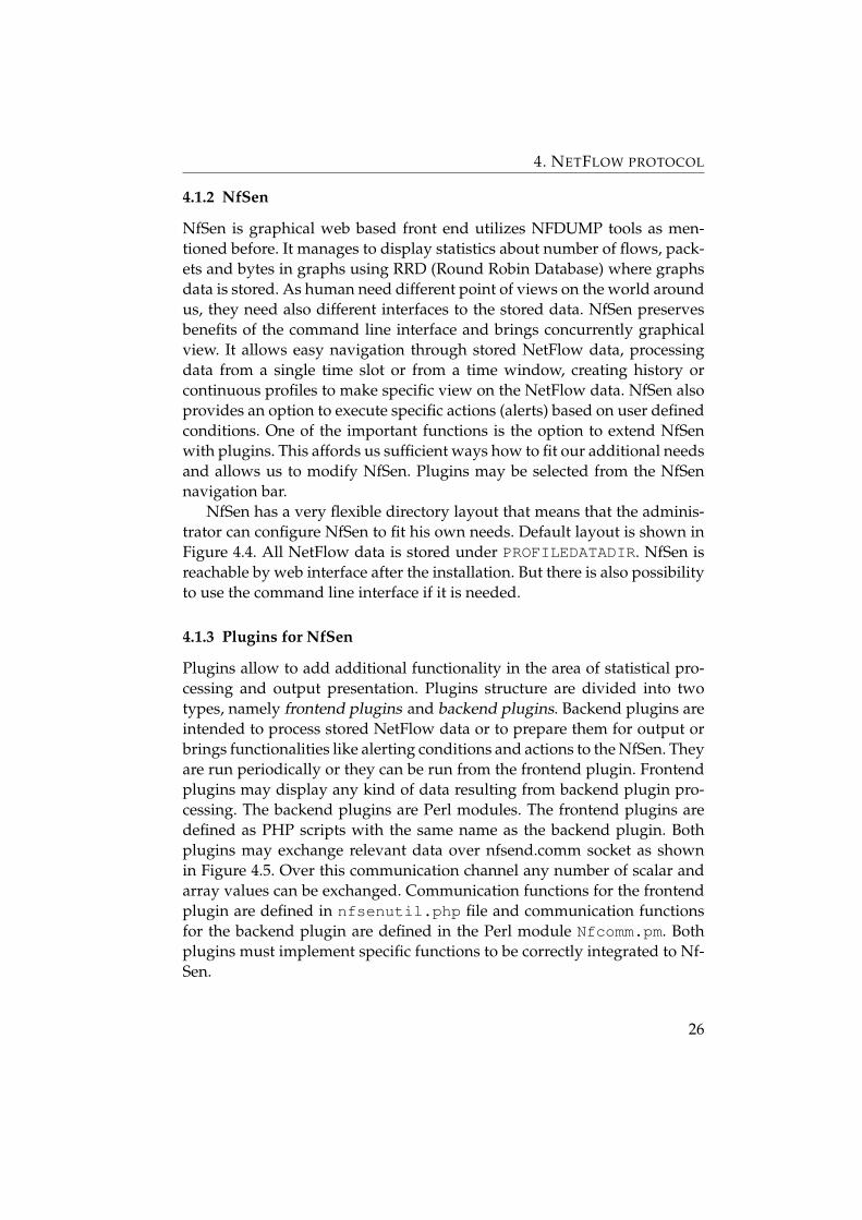
4.1.2 NfSen
NfSen is graphical web based front end utilizes NFDUMP tools as men-tioned before. It manages to display statistics about number of flows, pack-ets and bytes in graphs using RRD (Round Robin Database) where graphsdata is stored. As human need different point of views on the world aroundus, they need also different interfaces to the stored data. NfSen preservesbenefits of the command line interface and brings concurrently graphicalview. It allows easy navigation through stored NetFlow data, processingdata from a single time slot or from a time window, creating history orcontinuous profiles to make specific view on the NetFlow data. NfSen alsoprovides an option to execute specific actions (alerts) based on user definedconditions. One of the important functions is the option to extend NfSenwith plugins. This affords us sufficient ways how to fit our additional needsand allows us to modify NfSen. Plugins may be selected from the NfSennavigation bar.
NfSen has a very flexible directory layout that means that the adminis-trator can configure NfSen to fit his own needs. Default layout is shown inFigure 4.4. All NetFlow data is stored under PROFILEDATADIR. NfSen isreachable by web interface after the installation. But there is also possibilityto use the command line interface if it is needed.
4.1.3 Plugins for NfSen
Plugins allow to add additional functionality in the area of statistical pro-cessing and output presentation. Plugins structure are divided into twotypes, namely frontend plugins and backend plugins. Backend plugins areintended to process stored NetFlow data or to prepare them for output orbrings functionalities like alerting conditions and actions to the NfSen. Theyare run periodically or they can be run from the frontend plugin. Frontendplugins may display any kind of data resulting from backend plugin pro-cessing. The backend plugins are Perl modules. The frontend plugins aredefined as PHP scripts with the same name as the backend plugin. Bothplugins may exchange relevant data over nfsend.comm socket as shownin Figure 4.5. Over this communication channel any number of scalar andarray values can be exchanged. Communication functions for the frontendplugin are defined in nfsenutil.php file and communication functionsfor the backend plugin are defined in the Perl module Nfcomm.pm. Bothplugins must implement specific functions to be correctly integrated to Nf-Sen.
26

4. NETFLOW PROTOCOL
Figure 4.5: Communication concept for backend and frotend plugins, figurefrom [18]
27
Chapter 5
Creation of DetectSkype plugin for NfSen
As a result of my measurements I have created a plugin for NfSen. I havedeveloped it for NfSen collector situated on nftest.ics.muni.cz. It pro-cesses flow records from 3 channels:
• 10GE connection between the Masaryk University network and CES-NET
• 1GE from/to the Faculty od Informatics
• 1GE from/to the Vinarska dormitory
Real traffic is monitored but the data is anonymized. That means that IPaddresses are anonymized but the characteristic of the flow records remainsuntouched.
The activity of the plugin can be divided into two ways. One is auto-matic and periodic processing of stored data and creation of statistics, theother one is processing user commands and presentation of results.
5.1 Backend plugin
Backend plugin is written in Perl language. The main part is by NfSen de-manded function run. It is run periodically with relevant parameters (pro-file, profilegroup, timeslot) every 5 minutes by NfSen. Data processed bythe plugin are stored in six database files. The database is simple BerkeleyDB, which is easily usable in Perl environment.
The question was what is characteristic for Skype activity from the flowpoint of view. As Skype client initiates every startup a TCP connection tospecific address, it was first rule that was considered for implementation.The SC sends an HTTP request to the HTTP server ui.skype.com tocheck the latest version of the application. This request is sent every fourhour and under normal conditions (e.g. no TCP RST flag is present in the
28

5. CREATION OF DETECTSKYPE PLUGIN FOR NFSEN
flow) 5 TCP packets are sent in both directions. Filter for nfdump that willgain flow records representing this rule follows:
proto tcp and $srcnet and dst ip $uiskypeaddressand dst port 80 and packets > 3
$srcnet is set to src net 147.250.0.0/16 as the university ad-dresses are anonymized to this mask. $uiskypeaddress is set to203.233.225.202 as this is the actual anonymized address for ui.skype.com.Used in real network, it can be set to ui.skype.com because fully quali-fied hostnames are supported by nfdump.
We will maintain IP addresses that were in connection with Skype HTTPserver for the last four hours and corresponding start time of the flow.
Next characteristic deals with voice call properties. As we can filter flowrecords in respect to bit rate and other useful fields, the filter for obtainingflows with voice characteristic will be:
proto udp and duration > 296000 and pps > 15and pps < 70 and bps > 13000and bps < 99000 and bpp < 300
As TCP voice calls use several connections to relays, I have focused onUDP calls. Since the characteristic of the voice call does not hold true forshort periods of time like at the beginning and at the end of calls whene.g. signalling packets are sent after the end of call and influence calculatedfields of the flow records, I have considered flow records that are spannedthrough the entire time slot – and that are 5 minutes long flow records. Asthe frames of sizes 20, 40, 60 msec are generated by SILK voice codec in therate 50, 25, 16 frames per second, I filter records with packets per secondvalue in this manner with some overhead to capture possible video call inhigher pps rate. The restriction for bit rate is similar. Video call propertiesintersect the ones of voice call. So not to gain only isolated records of videocalls sometimes, I have increased the tolerance for bit rate over the maximalvalue for voice bit rate. Bytes per packet are set according to my measure-ments. During processing of flows with given properties there is also checkfor the identical flow records. As outside trafic e.g. from CESNET to theFaculty of Informatics should be captured at two channels, there will bealmost identical flow records for a given flow. They are eliminated by thecheck for almost identical start time field (threshold difference 3 seconds).Each flow with given properties is stored to the database. Every new flow inthe next time slot is checked against these stored flows. If positive match isfound i.e. source address, source port, destination address, destination portmatch, then these flows are merged together. If some flow is not mergedwith some new flow, then it is considered that the voice call has ended and
29

5. CREATION OF DETECTSKYPE PLUGIN FOR NFSEN
this flow is exported to the history database with additional values likeUDP port (values are explained further in the frontend plugin section).
Next characteristic for the Skype client is the used UDP port. It is usedas the source and incoming port for the UDP protocol. It is set in the Con-nection dialog of the client so it is not dynamically changed during the runof application. I have searched for this port in two situations. The first oneis the moment when the connection to the HTTP server is detected. Thenin the next time slot, the IP addresses are searched for the correspondingUDP ports. Skype initiates UDP probes during the whole Skype sessionand, from the flow point of view, the flow consists of one packet because inthe future generated probes to the same peer will belong to the new flow.The filter is:
proto udp and src port > 1024 and bpp < 80and bpp > 40 and packets = 1and src ip in $filter addresses
Bytes per packet are limited thanks to the packet length statistics I havegained from my Skype standby measurements. I have also tested the pro-posed plugin implementation and when filtering processed data I have rec-ognized BitTorrent activity. I have done several measurements to find outhow similar BitTorrent UDP probing activity is to the one of Skype. Most ofthe UDP probe packets have sizes greater than 90 bytes. For UDP packets ofSkype standby measurement (from 67 hours lasting log) I can see followingpackets statistics:
Packetlengths Count Percent
40− 79 8472 52.98%
80− 159 522 3.26%
160− 319 6835 42.75%
320− 639 161 1.01%
So I have limited bytes per packet according to these values to get bet-ter results. As there will be lot flows, flows are aggregated by IP sourceaddress and port and the aggregated flows are sorted according to aggre-gation number. Record with most flows is chosen as the representative andcorresponding source port is selected as possible UDP port of the Skype ap-plication as concurrently with detected Skype activity there must be UDPprobes present.
Second situation, as mentioned before, when the UDP port is searched.With the start of potential voice call it is time to check for the UDP port asat the beginning of voice call there is a burst of UDP probes always.
30

5. CREATION OF DETECTSKYPE PLUGIN FOR NFSEN
Figure 5.1: DetectSkype plugin frontend.
As we check UDP ports at two different times, we increase the prob-ability that the port does not belong to some other network activity at aparticular IP address.
As voice calls are bidirectional flows, I wanted to consider this charac-teristic too. I have find out that sometimes there are missing flow records onthe collector side. To avoid dividing some continuously monitored poten-tial call I have implemented another approach. The plugin calculates num-ber of incoming flows to our designated IP address and port at the startof the potential call. Characteristic of the flows allows us to detect possiblevideo calls with high bit rates. This characteristic is used because outgo-ing voice call can be detected correctly but in the opposite direction hugevideo traffic will not be recognized as Skype flow. This could lead to not rec-ognizing our flow as Skype traffic as there would be missing bidirectionalpattern.
proto udp and duration > 296000 and pps > 10and pps < 210 and bps > 8000and bps < 2000000 and $filter addr port
Aggregation on destination address and port is used and records arearranged according to number of flows.
5.2 Frontend plugin
Frontend plugin is a component of the NfSen web interface. It implementstwo mandatory functions DetectSkype ParseInput andDetectSkype Run. DetectSkype ParseInput is intended to to parsepossible form data and is called after selection in the plugins tab.DetectSkype Run is the main function, it is up to it what will be displayedin the web browser and parameters will be sent to the backend plugin.
There are several options what scope of values to display in the web
31
5. CREATION OF DETECTSKYPE PLUGIN FOR NFSEN
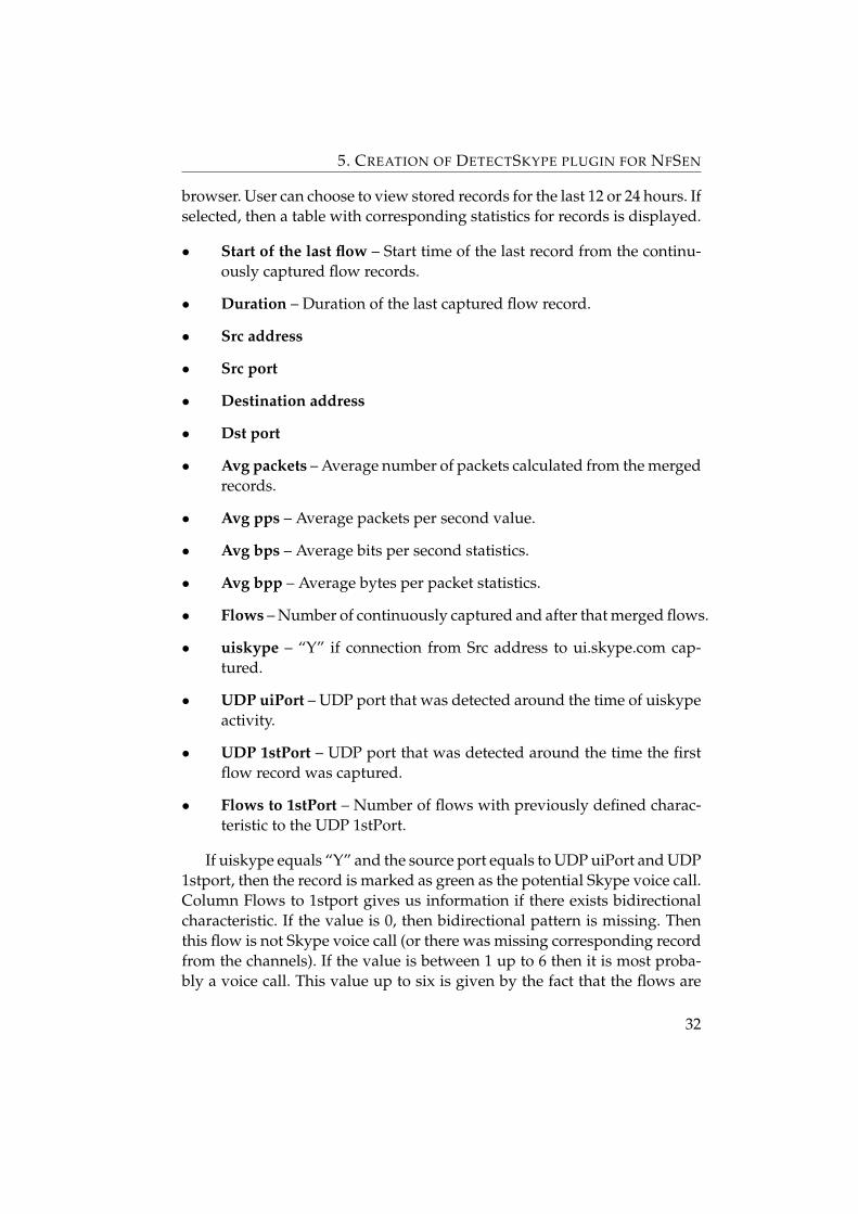
browser. User can choose to view stored records for the last 12 or 24 hours. Ifselected, then a table with corresponding statistics for records is displayed.
• Start of the last flow – Start time of the last record from the continu-ously captured flow records.
• Duration – Duration of the last captured flow record.
• Src address
• Src port
• Destination address
• Dst port
• Avg packets – Average number of packets calculated from the mergedrecords.
• Avg pps – Average packets per second value.
• Avg bps – Average bits per second statistics.
• Avg bpp – Average bytes per packet statistics.
• Flows – Number of continuously captured and after that merged flows.
• uiskype – “Y” if connection from Src address to ui.skype.com cap-tured.
• UDP uiPort – UDP port that was detected around the time of uiskypeactivity.
• UDP 1stPort – UDP port that was detected around the time the firstflow record was captured.
• Flows to 1stPort – Number of flows with previously defined charac-teristic to the UDP 1stPort.
If uiskype equals “Y” and the source port equals to UDP uiPort and UDP1stport, then the record is marked as green as the potential Skype voice call.Column Flows to 1stport gives us information if there exists bidirectionalcharacteristic. If the value is 0, then bidirectional pattern is missing. Thenthis flow is not Skype voice call (or there was missing corresponding recordfrom the channels). If the value is between 1 up to 6 then it is most proba-bly a voice call. This value up to six is given by the fact that the flows are
32

5. CREATION OF DETECTSKYPE PLUGIN FOR NFSEN
Figure 5.2: DetectSkype plugin frontend, first rows of statistics for the thelast 24 hours. 33

5. CREATION OF DETECTSKYPE PLUGIN FOR NFSEN
Figure 5.3: DetectSkype plugin frontend, statistics for one IP address.34

5. CREATION OF DETECTSKYPE PLUGIN FOR NFSEN
counted for more then one time slot and if the flow record is captured at bytwo channels at the same time, we can get value up to six for continuousvoice call. Values higher are most probably not voice calls. But when Skypeclient is at conference call, then more incoming flows can be detected. Sothere is third option for displaying data statistics, namely for a particularIP address. Records for this option are stored for two weeks and records inwhich given address figures as source address or destination address aredisplayed. In Figure 5.3, there is visible how BitTorrent was filterd out bybetter choosing parameters for searching UDP ports. The most upper rowshows us a voice call that has lasted for three time slots. That means thatthe start of the voice call was detected approximately at 12:26:40. At thattime we can observe flow has bidirectional character to our voice call. Herewe can also see that the flow from address 80.243.43.49 has missing flowrecord for the start time at 12:31:39 but the flow was present. This alsoclearly visible by the fact that two displayed flows have start time as multi-plication of 5 minutes.
35

Chapter 6
Conclusion
I have studied network traffic of the Skype application in this thesis. I haveconfirmed some detected traffic or payload patterns presented by othersfor earlier versions of Skype client. My contribution was verification of pro-posed papers related to this field for newer versions of application – 4.1,4.2 and 5.3 – and discovering new facts that were not published so far asI know. I have proposed e.g. new facts about TCP signalling traffic. Fromthe presented facts it is possible to create data payload analyzer that willrecognize Skype traffic quite efficient as similarly mentioned in [1]. Thereare several other techniques how to reveal Skype traffic. One method basedon Pearson’s Chi Square test is used to detect Skype’s fingerprints from thepacket framing structure, exploiting the randomness introduced at the bitlevel by the encryption process [5]. There can also be used some machinelearning algorithms like AdaBoost or C4.5 [3].
Further in this thesis I have created plugin for NfSen with its backendand frontend part. As NetFlow records do not offer data payload for inspec-tion, approach different to payload analysis was used. Limitations are thatit is quite difficult to recognize TCP relayed traffic as several connectionswith no constant traffic and with dynamical source ports is present, so itwas not possible to consider this kind of detection. Limitation for proposedplugin is that we do not have calculation for the probability the Skype voicecall was recognized correctly.
36

Bibliography
[1] Davide Adami, Christian Callegari, Stefano Giordano, MichelePagano, and Teresa Pepe. A Real-Time Algorithm for Skype TrafficDetection and Classification. In Sergey Balandin, Dmitri Moltchanov,and Yevgeni Koucheryavy, editors, Smart Spaces and Next GenerationWired/Wireless Networking, 9th International Conference, NEW2AN2009 and Second Conference on Smart Spaces, ruSMART 2009, St. Pe-tersburg, Russia, September 15-18, 2009. Proceedings, volume 5764 ofLecture Notes in Computer Science, pages 168–179. Springer, 2009.
[2] C. Allen and T. Dierks. RFC 2246 – The TLS Protocol Version 1.0.http://tools.ietf.org/html/rfc2246, January 1999.
[3] Duffy Angevine and A. Nur Zincir-Heywood. A preliminary investi-gation of skype traffic classification using a minimalist feature set. InARES, pages 1075–1079. IEEE Computer Society, 2008.
[4] Salman Baset and Henning Schulzrinne. An analysis of the skype peer-to-peer internet telephony protocol. In INFOCOM. IEEE, 2006.
[5] Dario Bonfiglio, Marco Mellia, Michela Meo, Dario Rossi, and PaoloTofanelli. Revealing skype traffic: when randomness plays with you.In Jun Murai and Kenjiro Cho, editors, Proceedings of the ACM SIG-COMM 2007 Conference on Applications, Technologies, Architectures,and Protocols for Computer Communications, Kyoto, Japan, August27-31, 2007, pages 37–48. ACM, 2007.
[6] B. Claise. RFC 3954 – Cisco Systems NetFlow Services Export Version9. http://tools.ietf.org/html/rfc3954, October 2004.
[7] Sven Ehlert and Sandrine Petgang. Analysis and Signature ofSkype VoIP Session Traffic. In Franunhofer FOKUS Technical ReportNGNISKYPE-06b, July 2006. Berlin, Germany.
[8] H. Astrom, J. Spittka and K. Vos. RTP Payload Format and File StorageFormat for SILK Speech and Audio Codec. http://developer.
37

6. CONCLUSION
skype.com/resources/SILK_RTP_PayloadFormat.pdf, Au-gust 2010.
[9] J. Rosenberg, R. Mahy, P. Matthews and D. Wing. RFC 5389 – SessionTraversal Utilities for NAT (STUN). http://tools.ietf.org/html/rfc5389, October 2008.
[10] Chun-Ming Leung and Yuen-Yan Chan. Network Forensic on En-crypted Peer-to-Peer VoIP Traffics and the Detection, Blocking, andPrioritization of Skype Traffics. In WETICE, pages 401–408. IEEE Com-puter Society, 2007.
[11] Jonathan Rosenberg. Skype and the Network, Technical Advi-sory Process Workshop on Broadband Network Management.http://www.openinternet.gov/workshops/docs/ws_tech_advisory_process/Skype-FCC.PPTX. Visited 27. 5. 2011.
[12] S. Jensen, K. Soerensen and K. Vos. SILK Speech Codecdraft-vos-silk-01. http://developer.skype.com/resources/draft-vos-silk-01.txt, March 2010.
[13] Andreas Thomann. Skype - A Baltic Success Story. https://infocus.credit-suisse.com/app/article/index.cfm?fuseaction=OpenArticle&aoid=163167&coid=7805&lang=EN, September 2006. Visited 21. 2. 2011.
[14] Skype – The Big Blog – 30 million people online on Skype.http://blogs.skype.com/en/2011/03/30_million_people_online.html. Visited 27. 4. 2011.
[15] Skype grows FY revenues 20%, reaches 663 mlnusers. http://www.telecompaper.com/news/skype-grows-fy-revenues-20-reaches-663-mln-users,March 2011. Visited 27. 4. 2011.
[16] IT Administrators guide. http://download.skype.com/share/business/guides/skype-it-administrators-guide.pdf.Visited 21. 2. 2011.
[17] NFDUMP. http://nfdump.sourceforge.net. Visited 25. 5. 2011.
[18] NfSen – Netflow Sensor. http://nfsen.sourceforge.net. Vis-ited 25. 5. 2011.
38

6. CONCLUSION
[19] SILK Data Sheet. http://developer.skype.com/resources/SILKDataSheet.pdf. Visited 21. 2. 2011.
[20] Free Skype calls and cheap calls to phones – Skype. http://www.skype.com. Visited 21. 2. 2011.
[21] Help for Skype: How much bandwidth does Skypeneed? https://support.skype.com/en/faq/FA1417/How-much-bandwidth-does-Skype-need. Visited 7. 4. 2011.
[22] Kazaa – Wikipedia, the free encyclopedia. http://en.wikipedia.org/wiki/Kazaa. Visited 21. 2. 2011.
[23] NetFlow – Wikipedia, the free encyclopedia. http://en.wikipedia.org/wiki/Netflow. Visited 20. 5. 2011.
[24] Skype – Wikipedia, the free encyclopedia. http://en.wikipedia.org/wiki/Skype. Visited 12. 5. 2011.
[25] SVOPC – Wikipedia, the free encyclopedia. http://en.wikipedia.org/wiki/SVOPC. Visited 20. 5. 2011.
39