Embed Size (px)
Citation preview
ANALYSIS AND DESIGN OF
TELECOMMUNICATION TOWERS FOR
EARTHQUAKE LOADING IN SRI LANKA FOR
SUSTAINABILITY
A.M.L.N. Gunathilaka
Sri Lanka Telecom PLC
Telephone:+94 -11-2451210; Fax:+94-11-2331426
E-mail: [email protected]
C.S.Lewanagamage
University of Moratuwa
Telephone:+ 94-11-2650567; Fax: : + 94-11-2651216
E-mail: [email protected]
M.T.R. Jayasinghe
University of Moratuwa
Telephone: +94-11-2650567; Fax: + 94-11-2651216
E-mail: [email protected]
Abstract
Large number of telecommunication towers has been constructed in Sri Lanka during last few
decades with the rapid development of telecommunication sector in the country. These towers
play a significant role especially in wireless communication and failure of such tower in a disaster
like an earthquake is major concern mainly in two ways. One is the failure of communication
facilities will become a major setback to carry out rescue operations during disaster while failure
of tower will itself cause a considerable economic loss as well as damages to human life in most
of the cases. Therefore, design of telecommunication towers considering all possible extreme
conditions is of utmost importance and a good design can be considered as a step towards a
greater degree of sustainability.
However, almost all telecommunication towers in this country have not been checked for
earthquake loading since most of people believe that earthquake threats are not that much of
significance to Sri Lanka until recently. With many tremors recorded in recent past, designers
have started to rethink about earthquake design of structures and main objective of this research is
assessing the performance of exiting towers (which were not initially designed considering
earthquake loading) under possible earthquake loading and find cost effective strategies for
retrofitting in case such action has to be effected.
Accordingly, behaviour of existing four legged Greenfield towers under seismic loadings
appropriate for Sri Lankan conditions were analyzed using equivalent static load method given in
ANSI/TIA-222-G. This can be considered as an initiative in this research area under local
conditions. Results and conclusions based on this analysis are discussed in this paper.
Key words: Telecommunication towers, earthquake loading

1. Introduction
Telecommunication towers has became an essential item especially in wireless
telecommunication sector with the development of wireless telecommunication technologies such
as CDMA (Code Division Multiple Access), GSM (Global System for Mobile ),WAP (wireless
Web Access), etc. In Sri Lankan context, most of telecommunication towers have been
constructed with the introduction of mobile telephone networks in early 1990s, even though there
are few towers which have histories over 30 years.
More than thousand telecommunication towers with various structural forms are available in this
country and almost all of these towers have been design only considering wind loading, since Sri
Lanka was considered as a country free from earthquakes until recently. However, with recent
recorded tremors in the range of 3 to 4 in Richter scale, the probability of occurrence of
earthquakes in the country is highlighted and design of buildings and other structures considering
seismic effects is also emphasized.
With these developments, most of the structural engineers in the country started to incorporate
seismic effects for their designs especially in building construction sector. But, for the designs of
telecommunication towers, seismic effects are not considered by the designers yet. Hence, a
comprehensive study in this regard is very important to ensure the safety of these towers during
possible earthquakes in future in terms of sustainable development.
A failure of a telecommunication tower especially during a disaster is a major concern in two
ways. Failure of telecommunication systems due to collapse of a tower in a disaster situation
causes a major setback for rescue and other essential operations. Also, a failure of tower will itself
cause a considerable economic loss as well as possible damages to human lives. Hence, analysis
of telecommunication towers considering all possible extreme conditions is of utmost importance.
The main objective of this research is assessing the performance of exiting towers (which were
not initially designed considering earthquake loading) under possible earthquake loading and
finding of cost effective strategies for retrofitting in case such action has to be effected.
However, various types of telecommunication towers with different structural forms are available
in the country and this study has been limited to analysis of four legged Greenfield self supporting
lattice towers, which are the most common type of telecommunication towers in this country.
In world context, various researches have been carried out regarding the behavior of
telecommunication towers under earthquake loadings and most of the Code of Practices such as
ANSI/TIA-222-G [1] , AS 3995-94 [2] used for tower designs have also incorporated guidelines
for analysis of towers under seismic loading. However, those data would not be directly
applicable for Sri Lankan context since local seismic conditions could be different from other
countries .
1. Methodology
Seismic effect on four legged Greenfield self supporting lattice towers were considered for this
analysis. Three towers having different tower heights of 30m, 50m and 80m were selected for this
analysis as most of the Green field telecommunication towers of Sri Lanka are within this height
range from 30m to 80m. All of these towers had been designed for wind speed of 50 m/s
(180km/h) , which is the recommended design wind speed for Zone 1 Normal structures
condition.
ANSI/TIA-222-G-2005 [1] Structural Standard for Antenna Supporting Structures and Antennas,
which is highly appreciated and very commonly used code of practice by both local and foreign
tower designers for their designs, was used for the structural analysis and design of towers under
both wind and seismic loadings.
3D computer models for each tower were prepared using SAP2000 structural analysis software
and analysis of towers under both wind an earthquake loads were carried out using such models.
Finally, the results of analyses under wind and earthquake loads were compared.
Designs of the towers were verified for design wind speed of 50m/s using computer analysis
results as the first step. Towers were also analyzed for the wind speed of 33.5m/s (recommended
design wind speed for Zone 3 Normal structures condition for Sri Lanka), which is the lowest
allowable design wind speed that can be used for structural design in Sri Lanka, for the purpose
of comparison of results.
For analysis of towers under earthquake loading, equivalent static methods given in ANSI/TIA-
222-G-2005 [1] were used. Appropriate seismic loads for Sri Lanka was selected as described in
section 3.2. Seismic loads were also calculated under very severe and severe seismic conditions
as well for the purpose comparison.
2. Loading
2.1 Wind loads
Calculation of wind loads on towers were carried out according to ANSI/TIA-222-G-2005[1] for
the design wind speed of 50m/s (180km/h) , which is the recommended design wind speed for
Zone 1 Normal structures condition. Wind loads were also calculated for the wind speed of
33.5m/s (recommended design wind speed for Zone 3 Normal structures condition for Sri Lanka),
which is the lowest allowable design wind speed that can be used for structural design in Sri
Lanka, for the purpose of comparison of results.
2.2 Seismic loads
For the calculation of seismic loads on towers, four methods are given in the ANSI/TIA-222-
G[1]. Those methods are;
1. Equivalent lateral force procedure
2. Equivalent Model analysis procedure
3. Model analysis procedure
4. Time history analysis
The first two methods of the above are equivalent static methods and the other two are response
spectrum and time history analysis procedures. The equivalent static methods have been used in
this study. For the selection of appropriate equivalent static method for an analysis, criteria has
been given in the ANSI/TIA-222-G[1] and accordingly for the 30m tower, method 1 was
selected, while method 2 was selected for 50m and 80m towers.
Calculation of equivalent static load for 30m tower
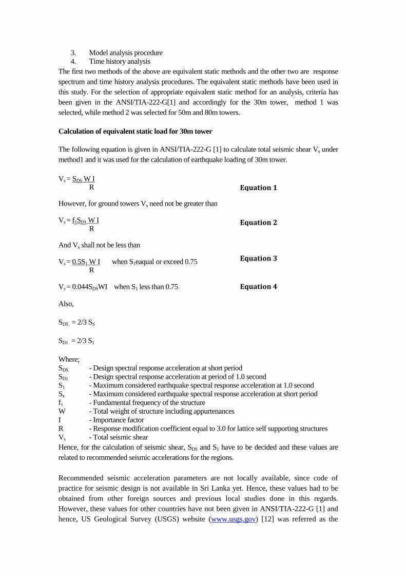
The following equation is given in ANSI/TIA-222-G [1] to calculate total seismic shear Vs under
method1 and it was used for the calculation of earthquake loading of 30m tower.
Vs = SDS W I R
However, for ground towers Vs need not be greater than
Vs = f1SD1 W I R
And Vs shall not be less than
Vs = 0.5S1 W I when S1eaqual or exceed 0.75 R
Vs = 0.044SDSWI when S1 less than 0.75
Also,
SDS = 2/3 SS
SD1 = 2/3 S1
Where;
SDS - Design spectral response acceleration at short period
SD1 - Design spectral response acceleration at period of 1.0 second
S1 - Maximum considered earthquake spectral response acceleration at 1.0 second
Ss - Maximum considered earthquake spectral response acceleration at short period
f1 - Fundamental frequency of the structure
W - Total weight of structure including appurtenances
I - Importance factor
R - Response modification coefficient equal to 3.0 for lattice self supporting structures
Vs - Total seismic shear
Hence, for the calculation of seismic shear, SDS and S1 have to be decided and these values are
related to recommended seismic accelerations for the regions.
Recommended seismic acceleration parameters are not locally available, since code of
practice for seismic design is not available in Sri Lanka yet. Hence, these values had to be
obtained from other foreign sources and previous local studies done in this regards.
However, these values for other countries have not been given in ANSI/TIA-222-G [1] and
hence, US Geological Survey (USGS) website (www.usgs.gov) [12] was referred as the
Equation 1
Equation 2
Equation 3
Equation 4

initial step to find relevant values. The recommended SS and S1 values for Sri Lanka in it are
0.03 and 0.01 respectively. Also , as per the research done by Peiris,2008 [11], Peak Ground
Acceleration at rock sites for a10% probability of exceedance in 50 year or 475year return
period is around 0.026g and this is quite match with recommended value given in
www.usgs.gov [12].But, researchers who previously carried out seismic designs for
buildings in Sri Lanka had gone for higher values considering lack of earthquake data
regarding pattern of loading, etc for Sri Lanka ( In the study on Performance of Tall
Buildings with and without Transfer Plate under Earthquake loading done by Jayasinghe M.
T. R. , Hettiarachchi D.S. , Gunawardena D. S. R. T. N. (2012) [9] had used seismic
acceleration in the range of 0.10g to 0.15g in their study). Accordingly, Ss and S1 were
selected as 0.35 and 0.08 assuming moderate damage condition ( Initially, Ss and S1 were
selected as 0.3 and 0.05 respectively and those were modified considering site specific
geotechnical condition as Site Class “ C” , since towers are constructed in hard soil
conditions in most of the instances). These values are conservative and appropriate figures
to use for seismic design in Sri Lanka, since Sri Lanka is a country where it is possible to
expect intraplate type of earthquakes.
Also, base shears were calculated for condition of Ss = 2.14 and S1 = 0.86 ( which are the values
recommended for Nepal by USGS, which has very high seismicity ,) and for condition of Ss =
1.22 and S1 = 0.49 (which are the values recommended for Pakistan, by USGS which has high
seismicity) to consider very severe and severe seismicity conditions respectively for comparison
purpose.
For the calculation of fundamental natural frequency of a tower, a formula has been given in
ANSI/TIA-222-G [1]. However, to obtain better accuracy, natural frequencies were obtained from
the modal analysis performed using SAP 2000 model and calculated fundamental natural
frequency is 3.21Hz for 30m tower. The vertical distribution of seismic force was done according
to following formula given in ANSI/TIA-222-G[1].
Fsz = Wz hzke
∑ Wi hi
ke
Where;
Fsz = Lateral seismic force at level Z
Wz = Portion of total gravity load assigned to level under consideration
Wi = Portion of total gravity load assigned to level i
hz = Height from the base of the structure to level under consideration
hi = Height from the base of the structure to level i
ke = seismic force distribution exponent (taken as 2.0 )
Calculation of equivalent static load for 50m and 80m towers
The formula given under equivalent model analysis procedure ( method 2) is as follows;
Fsz = Saz Wz I R
Where;
Fsz = Lateral seismic force at level under consideration
Saz = Acceleration coefficient at height z
Equation 5
Equation 6

= a (SA)2 + b (SDS)
2
{ (SA)2 + c (SDS)
2}
1/2
a,b,c = Acceleration coefficients
SA = SD1f1 when f1 <= SDS/SD1, otherwise SA =SDS
f1 = fundamental frequency of structure
SDS = Design spectral response acceleration at short period
SD1 = Design spectral response acceleration at period of 1.0 second
Wz = Portion of gravity load assigned to level under consideration
I = Importance factor
The fundamental frequencies (2.7Hz for 50m tower and 1.37Hz for 80m tower) of respective
towers were obtained from modal analysis of SAP2000 models and equivalent static loads were
calculated for same three different conditions described under 30m tower case for comparison
purpose.
Equation 7
30m tower
Frequency of
1stmode =3.21Hz
50m tower
Frequency of
1stmode =3.21Hz
80m tower
Frequency of
1stmode =1.37Hz
Figure 1 – Tower models

3. Three Dimensional Modeling
As mentioned earlier, 3D finite element truss models were prepared for all three (30m, 50m and
80m) towers. All structural members of these towers were defined as standard “L” angel
members and Grade of steel of leg members were considered as S355 and all other members as
S275 as in actual towers.
Each of the towers was subdivided to panels according to geometries of towers and wind and
earthquake loads were separately calculated for each panel. The calculated wind and earthquake
loads were for each panel were assigned as nodal loads for respective tower models.
Since maximum support reactions and stresses in leg members are developed when lateral loads
are applied along a diagonal of the plan of a tower, both wind and seismic loads are applied along
a diagonal direction. As per ANSI/TIA-222-G[1] specifications, following load cases given in
Table 1 were considered in this study.
Results of the modal analysis of respective towers were used to calculate equivalent static loads
under earthquake loading.
Load
case
Case Name Partial safety factors Remarks
Dead Wind Earth.
1 1.2XDead +
1.6XWind 1.2 1.6 - Under 50m/s wind speed
2 0.9XDead +
1.6XWind
0.9 1.6 - Under 50m/s wind speed
3 1.2XDead +
1.6XWind 1.2 1.6 - Under 33.5m/s wind speed
4 0.9XDead +
1.6XWind
0.9 1.6 - Under 33.5m/s wind speed
5 1.2XDead +
1.0XEarth.
1.2 - 1.0 Earthquake load under Appropriate
condition for Sri Lanka
6 0.9XDead +
1.0XEarth.
0.9 - 1.0 Earthquake load under Appropriate
condition for Sri Lanka
7 1.2XDead +
1.0XEarth.
1.2 - 1.0 Earthquake load under very severe
seismicity condition
8 0.9XDead +
1.0XEarth.
0.9 - 1.0 Earthquake load under very severe
seismicity condition Under very severe
seismicity 9 1.2XDead +
1.0XEarth.
1.2 - 1.0 Earthquake load under severe seismicity
condition
10 0.9XDead +
1.0XEarth.
0.9 - 1.0 Earthquake load under severe
seismicity condition
Table 1- Load Cases considered for analysis
4. Analysis Results
Supports reactions, maximum axial forces in leg members and maximum horizontal deflections of
each tower with respect to the load combination describe above were obtained from SAP 2000
analysis results of respective tower models.
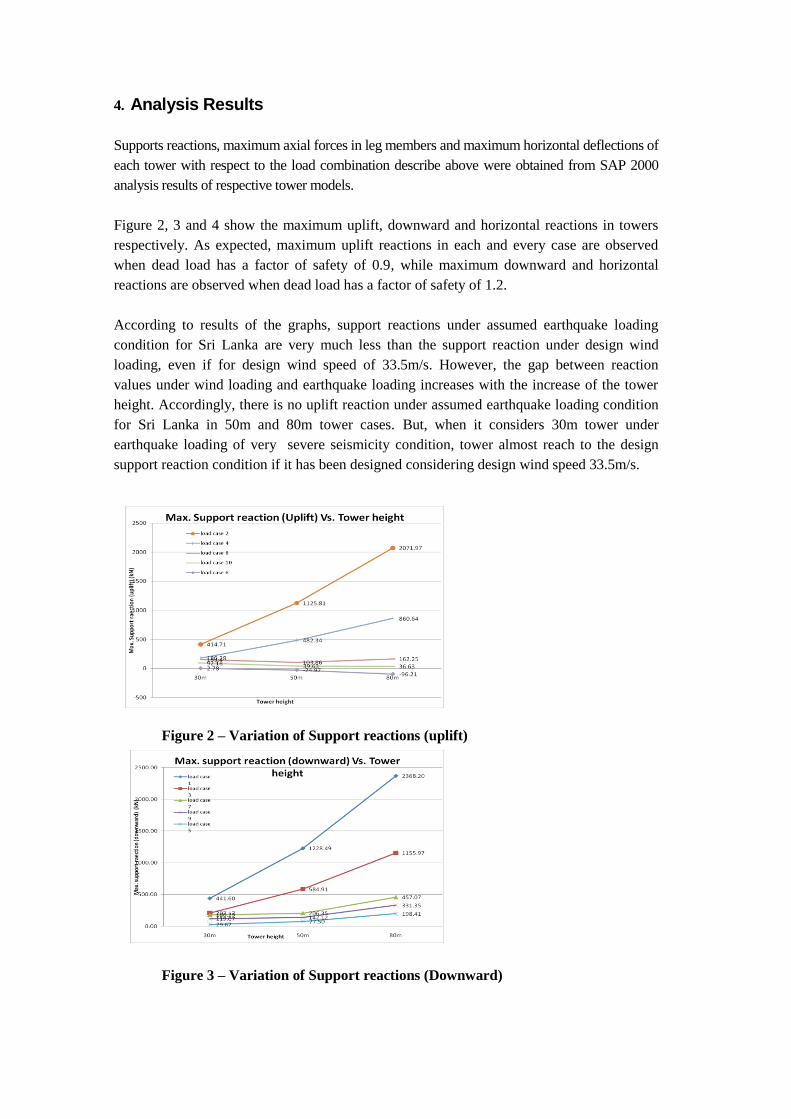
Figure 2, 3 and 4 show the maximum uplift, downward and horizontal reactions in towers
respectively. As expected, maximum uplift reactions in each and every case are observed
when dead load has a factor of safety of 0.9, while maximum downward and horizontal
reactions are observed when dead load has a factor of safety of 1.2.
According to results of the graphs, support reactions under assumed earthquake loading
condition for Sri Lanka are very much less than the support reaction under design wind
loading, even if for design wind speed of 33.5m/s. However, the gap between reaction
values under wind loading and earthquake loading increases with the increase of the tower
height. Accordingly, there is no uplift reaction under assumed earthquake loading condition
for Sri Lanka in 50m and 80m tower cases. But, when it considers 30m tower under
earthquake loading of very severe seismicity condition, tower almost reach to the design
support reaction condition if it has been designed considering design wind speed 33.5m/s.
Figure 2 – Variation of Support reactions (uplift)
Figure 3 – Variation of Support reactions (Downward)
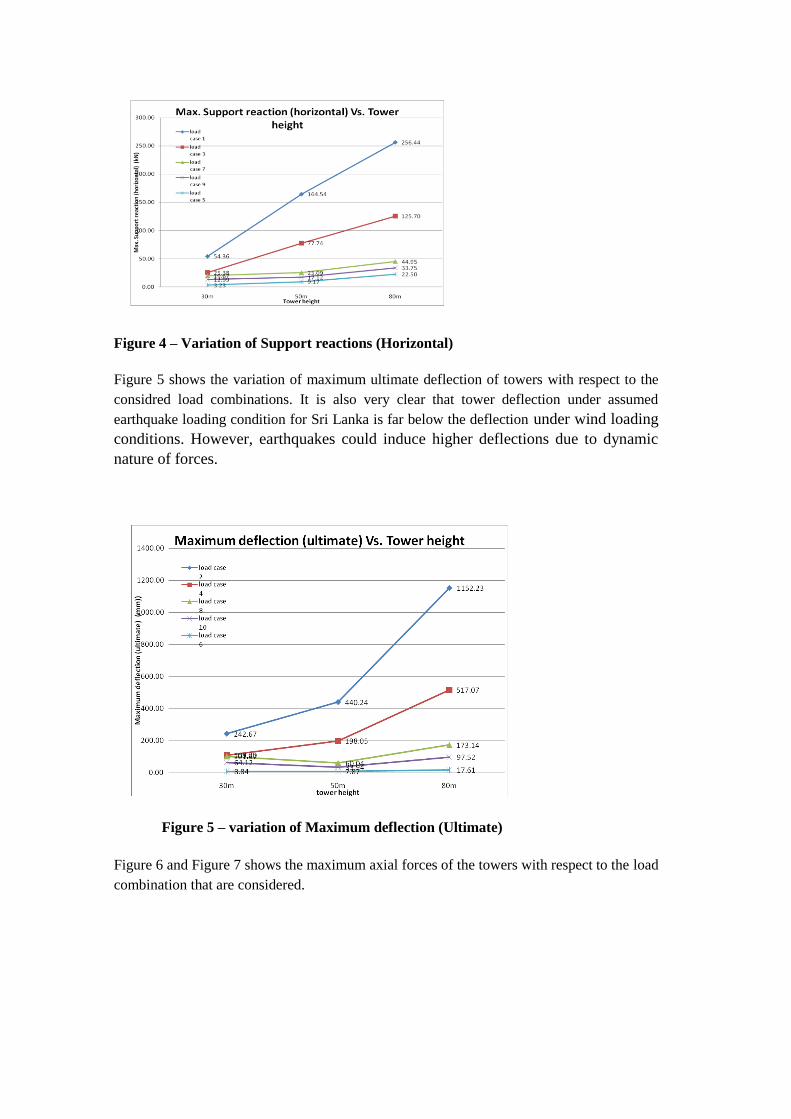
Figure 4 – Variation of Support reactions (Horizontal)
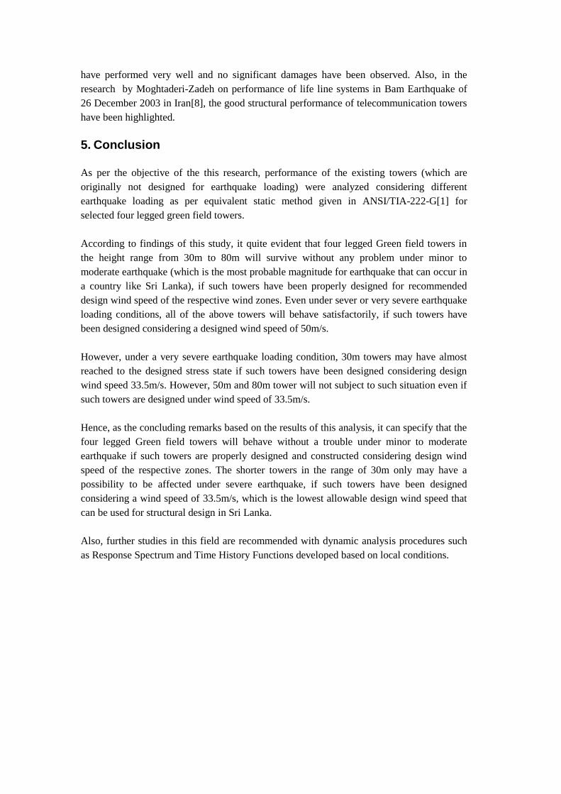
Figure 5 shows the variation of maximum ultimate deflection of towers with respect to the
considred load combinations. It is also very clear that tower deflection under assumed
earthquake loading condition for Sri Lanka is far below the deflection under wind loading
conditions. However, earthquakes could induce higher deflections due to dynamic
nature of forces.
Figure 5 – variation of Maximum deflection (Ultimate)
Figure 6 and Figure 7 shows the maximum axial forces of the towers with respect to the load
combination that are considered.

Maximum axial forces (both compression and tension) in leg members vary in same way as
in support reactions. Axial tensile stress in leg members have not been developed under
assumed Sri Lankan earthquake condition in both 50m and 80m tower cases. This means the
uplift force that develops due to overturning moment due to earthquake loading is less than
the self weight of the tower. In other words this means, member stresses developed under
assumed earthquake loading for Sri Lanka is insignificant compared with member stresses
under design wind load condition of towers. However, under earthquake loading calculated
based on very severe seismicity condition, axial forces of leg members has almost reached
the design values under 33.5m/s wind load.
The results obtained from this study match with the results of previous studies carried out in
other countries in this regard. A research carried out by Amiri and Boostan in 2002[6]
regarding telecommunication towers in Iran has observed a similar behavior where design
forces/reactions under wind loads is always dominant with respect to earthquake loading and
difference between magnitude of forces/reaction under wind load and seismic loading are
increasing when height of the tower is increased. Also, ANSI/TIA-222-G-2005[1] in itself
has specified that analysis under earthquake loading for normal towers are not required if Ss
is less than or equal to 1.00. This has also been proved by this analysis.
The better performance of the telecommunication towers under seismic loads that is
observed in this analysis has also been practically observed under actual earthquakes.
According to the field report prepared on structural and geotechnical damages sustained
during the 26 January 2001 M 7.9 Bhuj Earthquake in Gujarat by Department of Civil
Engineering, Indian Institute of Technology, Kanpur [10] , the telecommunication tower
Figure 6- variation of max. Axial tension
in leg members
Figure 7- variation of max. Axial
compression in leg members
have performed very well and no significant damages have been observed. Also, in the
research by Moghtaderi-Zadeh on performance of life line systems in Bam Earthquake of
26 December 2003 in Iran[8], the good structural performance of telecommunication towers
have been highlighted.
5. Conclusion
As per the objective of the this research, performance of the existing towers (which are
originally not designed for earthquake loading) were analyzed considering different
earthquake loading as per equivalent static method given in ANSI/TIA-222-G[1] for
selected four legged green field towers.
According to findings of this study, it quite evident that four legged Green field towers in
the height range from 30m to 80m will survive without any problem under minor to
moderate earthquake (which is the most probable magnitude for earthquake that can occur in
a country like Sri Lanka), if such towers have been properly designed for recommended
design wind speed of the respective wind zones. Even under sever or very severe earthquake
loading conditions, all of the above towers will behave satisfactorily, if such towers have
been designed considering a designed wind speed of 50m/s.
However, under a very severe earthquake loading condition, 30m towers may have almost
reached to the designed stress state if such towers have been designed considering design
wind speed 33.5m/s. However, 50m and 80m tower will not subject to such situation even if
such towers are designed under wind speed of 33.5m/s.
Hence, as the concluding remarks based on the results of this analysis, it can specify that the
four legged Green field towers will behave without a trouble under minor to moderate
earthquake if such towers are properly designed and constructed considering design wind
speed of the respective zones. The shorter towers in the range of 30m only may have a
possibility to be affected under severe earthquake, if such towers have been designed
considering a wind speed of 33.5m/s, which is the lowest allowable design wind speed that
can be used for structural design in Sri Lanka.
Also, further studies in this field are recommended with dynamic analysis procedures such
as Response Spectrum and Time History Functions developed based on local conditions.

References
1. ANSI/TIA-222-G 2005, Structural Standard for Antenna Supporting Structures and
Antennas, Telecommunications Industry Association ,USA
2. Australian Standard AS 3995, Design of Steel Lattice Towers and Masts, Australia
Standards Association, Sydney, Australia, 1994
3. CP3 : Chapter V : Part 2 : September : 1972 , Code of Basic Data for the design of
buildings Chapter V. Loading- part 2 wind load, British Standard Institution, United
Kingdom.
4. Design of buildings for high winds – Sri Lanka Ministry of Local Government, Housing
and Construction, Sri Lanka, 1980.
5. Khedr M. A. H., “Seismic analysis of lattice towers”, PhD thesis- McGill University ,
Montreal, Canada, 1998.
6. Ghodrati Amiri G., Boostan A., “ Dynamic Response of Antenna Supporting Structures
“, 4th Structural Specialty Conference of the Canadian Society of Civil Engineers,
Canada, 2002.
7. Ghodrati Amiri G.,Barkhordari M.A., Massah S.R. , “Seismic Behaviour of 4 – Legged
Self –Supporting Telecommunication Structures” , 13th World Conference on Earthquake
Engineering, Vancouver, Canada, 2004.
8. Masoud Moghtaderi-Zadeh, Farrokh Nadim, and Mohammad Javad Bolourchi
“Performance of Lifeline Systems in Bam Earthquake of 26 December 2003”, Journal of
Seismology and Earthquake Engineering-JSEE, Iran, 2004.
9. Jayasinghe M. T. R. , Hettiarachchi D.S. , Gunawardena D. S. R. T. N. , “ Performance
of Tall Buildings with and without Transfer Plate under Earthquake laoding” Engineer,
Journal of Institution of Engineers, Sri Lanka, Volume XXXXV, No.02, pp13-22, 2012.
10. A field report on structural and geotechnical damages sustained during the 26 January
2001 M7.9 Bhuj Earthquake in Western India , Department of Civil Engineering,Indian
Institute of Technology Kanpur, India, 2001.
11. Peiris L.M.N., “Seismic Hazard Assessment of Sri Lanka and Seismic Risk in
Colombo”, Risk Management Solutions, London, UK, 2008.
12. US Geological Survey (USGS) website (www.usgs.gov).