Embed Size (px)
Citation preview

48 th Turbomachinery & 35 th Pump Symposia | Sept. 9-12, 2019
Analysis and countermeasure for Sulfide Stress Cracking of Centrifugal compressor
Sanggyn Kwon / Bumsu Kim
Sangjoo Lee / Seokho Seo

T U R B O M A C H I N E R Y & P U M P S Y M P O S I A
Presenter/Author bios Presenter, Mr. Sanggyn Kwon
Engineer in Rotating machinery Reliability & Engineering Team of SK Energy, Korea, since 2012.
Received a B.S.degree (Material Engineering from Yonsei University, Korea).
Co-author. Mr. Bumsu Kim.
Team Leader of Rotating machinery Reliability & Engineering Team for SK Energy, Korea.
Received a B.S.degree (Mechanical Engineering from Busan National University, Korea)
and a key member of KRMEA(Korea Rotating Machinery Engineers Association).
Co-author. Mr. Sangjoo Lee .
Rotating machinery engineer in reliability for SK Energy, Korea, since 2007.
Received a M.S. degree(Mechanical Engineering from Ulsan University, Korea) and a key member of KRMEA(Korea Rotating Machinery Engineers Association)
Co-author. Mr. Seokho Seo .
Rotating machinery engineer in reliability for SK Energy Ulsan, Korea, since 2007.
Received a B.S. degree(Mechanical Engineering from Kyungbuk University, Korea)

T U R B O M A C H I N E R Y & P U M P S Y M P O S I A
In this case study
In case of compressors operated in environment of wet hydrogen sulfide, Sulfide Stress Cracking could act critical mechanism of impeller failure. This C/S deal with what make sulfide stress cracking and how to take a countermeasure to prevent recurrence of sulfide stress cracking, based on 2 cases of impeller failure from recycle gas compressor of Middle Distillation Unit(MDU) and Residue Hydro De-sulfurization Unit (RHDS) in refinery plants.

T U R B O M A C H I N E R Y & P U M P S Y M P O S I A
1. What is Sulfide Stress Cracking?
• Sulfide stress cracking (SSC) is a form of hydrogen embrittlement which is a cathodic cracking mechanism. Susceptible alloys, especially steels, react with hydrogen sulfide, forming metal sulfides and atomic hydrogen as corrosion byproducts. Atomic hydrogen either combines to form H2 at the metal surface or diffuses into the metal matrix.
• Sulfide stress cracking has special importance in the gas and oil industry, as the materials being processed there (natural gas and crude oil) often contain considerable amounts of hydrogen sulfide.
T U R B O M A C H I N E R Y & P U M P S Y M P O S I A
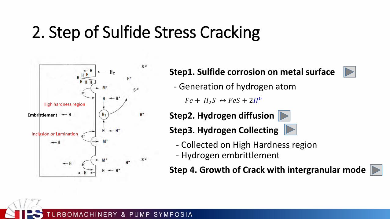
2. Step of Sulfide Stress Cracking
Step1. Sulfide corrosion on metal surface
- Generation of hydrogen atom
Step2. Hydrogen diffusion
Step3. Hydrogen Collecting
- Collected on High Hardness region - Hydrogen embrittlement
Step 4. Growth of Crack with intergranular mode
CH4
Embrittlement
High hardness region
Inclusion or Lamination
𝐹𝑒 + 𝐻2𝑆 ↔ 𝐹𝑒𝑆 + 2𝐻0

T U R B O M A C H I N E R Y & P U M P S Y M P O S I A
Wet H2S Environment
3. Mechanism of Sulfide Stress Cracking
Low Temperature (under 83℃)
Low pH
High hardness
& Stress Concentration
Metal corrosion and Generation of Hydrogen atom
Hydrogen Atom collecting on high hardness position
(H2S + Fe →FeS + 2H) Hydrogen Embrittlement
Sulfide Stress Cracking growth
Intergranular mode
T U R B O M A C H I N E R Y & P U M P S Y M P O S I A
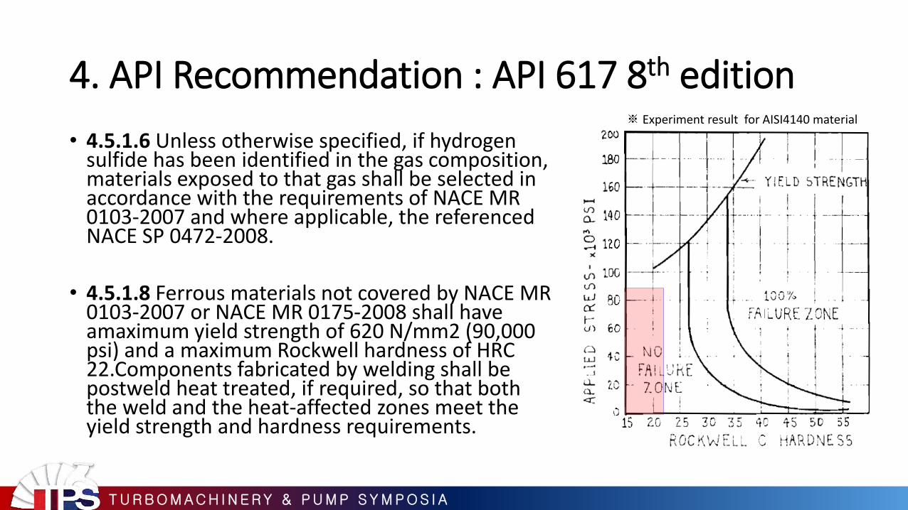
4. API Recommendation : API 617 8th edition
• 4.5.1.6 Unless otherwise specified, if hydrogen sulfide has been identified in the gas composition, materials exposed to that gas shall be selected in accordance with the requirements of NACE MR 0103-2007 and where applicable, the referenced NACE SP 0472-2008.
• 4.5.1.8 Ferrous materials not covered by NACE MR 0103-2007 or NACE MR 0175-2008 shall have amaximum yield strength of 620 N/mm2 (90,000 psi) and a maximum Rockwell hardness of HRC 22.Components fabricated by welding shall be postweld heat treated, if required, so that both the weld and the heat-affected zones meet the yield strength and hardness requirements.
※ Experiment result for AISI4140 material

T U R B O M A C H I N E R Y & P U M P S Y M P O S I A
Case Study Trouble Shooting Case 1

T U R B O M A C H I N E R Y & P U M P S Y M P O S I A
Trouble History and Information 1. Trouble History
• Trouble year and equipment : 2015. Centrifugal compressor • Source : Compressor Trip by Vibration High-High on Low Pressure Casing • Position : 1st Impeller • Vibration Trend : Rapid increasing to 320㎛ just before the trip
2. Equipment Information
Process Middle Distillation Hydro-desulfurization Unit
Initial Start-up 1991
Equipment Function Recycle Gas Compressor
Service Gas Main Hydrogen with other contents
Suction / Discharge Pressure (kg/cm2g) 37.77 / 56.25
Driver Steam Turbine

T U R B O M A C H I N E R Y & P U M P S Y M P O S I A
Inspection
Suction Discharge
Coupling
1st Impeller Suction Side Labyrinth
• 1st impeller was cracked completely • Wet contaminant on suction side • Heavy fouling on labyrinth

T U R B O M A C H I N E R Y & P U M P S Y M P O S I A
Fractography Crack initiated from Key groove of impeller
Intergranular Crack High concentration of Sulfur on Surface (EDS) and pH4
Corrosion Pit
Additional Cracks on Key Groove (w/Corrosion pit , 2nd Crack)
Stress concentrated on Key groove
Hardness of Impeller : Max HB 261
1 2
3
4 5 6

T U R B O M A C H I N E R Y & P U M P S Y M P O S I A
Root Cause Analysis
Features Material & Design
• Inter Granular Crack
• Secondary Crack
• Crack initiated from Key
Groove
Environment
• High Hardness1) (HB 261)
• Stress Concentration on
Key Groove
• Wet H2S Gas Composition
• Low pH (pH4)
• Low Temperature (49℃)
Sulfide Stress Cracking

T U R B O M A C H I N E R Y & P U M P S Y M P O S I A
Countermeasure 1. To approve the corrosion resistance - High alloy steel selection to improve for corrosion resistance - Material selection according to NACE MR0103 for Wet H2S environment (Hardness) 2. To decrease the stress concentration - Avoiding high stress concentration on rotor (Keyless type impeller)
Key Assembly Keyless Assembly

T U R B O M A C H I N E R Y & P U M P S Y M P O S I A
Case Study Trouble Shooting Case 2

T U R B O M A C H I N E R Y & P U M P S Y M P O S I A
Trouble History and Information 1. Trouble History
Trouble year : 2017. Source : Compressor Trip by Vibration High-High on Low Pressure Casing Position : 1st Impeller Vibration Trend : step changed and tripped in a few minutes
2. Equipment Information
Process Residue Hydrogen De-Sulfurization
Initial Start-up 1997
Equipment Function Recycle Gas Compressor
Service Gas Main Hydrogen with other contents
Suction / Discharge Pressure (kg/cm2g) 164 / 209
Driver Steam Turbine
Step Increasing before trip
Trip (max 135um)
Alarm : 30um Trip : 60um

T U R B O M A C H I N E R Y & P U M P S Y M P O S I A
Inspection 1st Impeller
1st Impeller Shaft Diaphragm
1
2 4
NDE Side (Suction)
DE Side (Disch)
3 1st Labyrinth

T U R B O M A C H I N E R Y & P U M P S Y M P O S I A
Fractography
Crack propagation with Chevron Pattern
Hardness of Initiation Point Max HB 339 (NACE Limit HB311)
Corrosion & Residual cracks at initiation Point
Quasi-Cleavage Pattern on crack surface

T U R B O M A C H I N E R Y & P U M P S Y M P O S I A
Root Cause Analysis
Features Material & Design
• Embrittlement crack
- Chevron Pattern
- Residual cracks
- Quasi-Cleavage Pattern
Environment
• High Hardness (HB 339)
• Welding area which High
stress is concentrated
• Corrosion environment due to
Wet H2S Gas Composition
• Low Temperature (59℃)
Sulfide Stress Cracking

T U R B O M A C H I N E R Y & P U M P S Y M P O S I A
Countermeasure 1. To prevent incorrect post weld heat treatment process - WELDLESS impeller
2. To inspect sulfide stress cracking - Periodical hardness measurement with portable devices (Vickers hardness) - Periodical inspection by WFMT(Wet Fluorescent Magnetic particle Test) (cracks underneath the surface, which cannot defines by PT inspection, can be inspected by WFMT)
machining
welding
With - Electric Discharge Machining - Electrochemical Machining
+ +

T U R B O M A C H I N E R Y & P U M P S Y M P O S I A
Summary
T U R B O M A C H I N E R Y & P U M P S Y M P O S I A
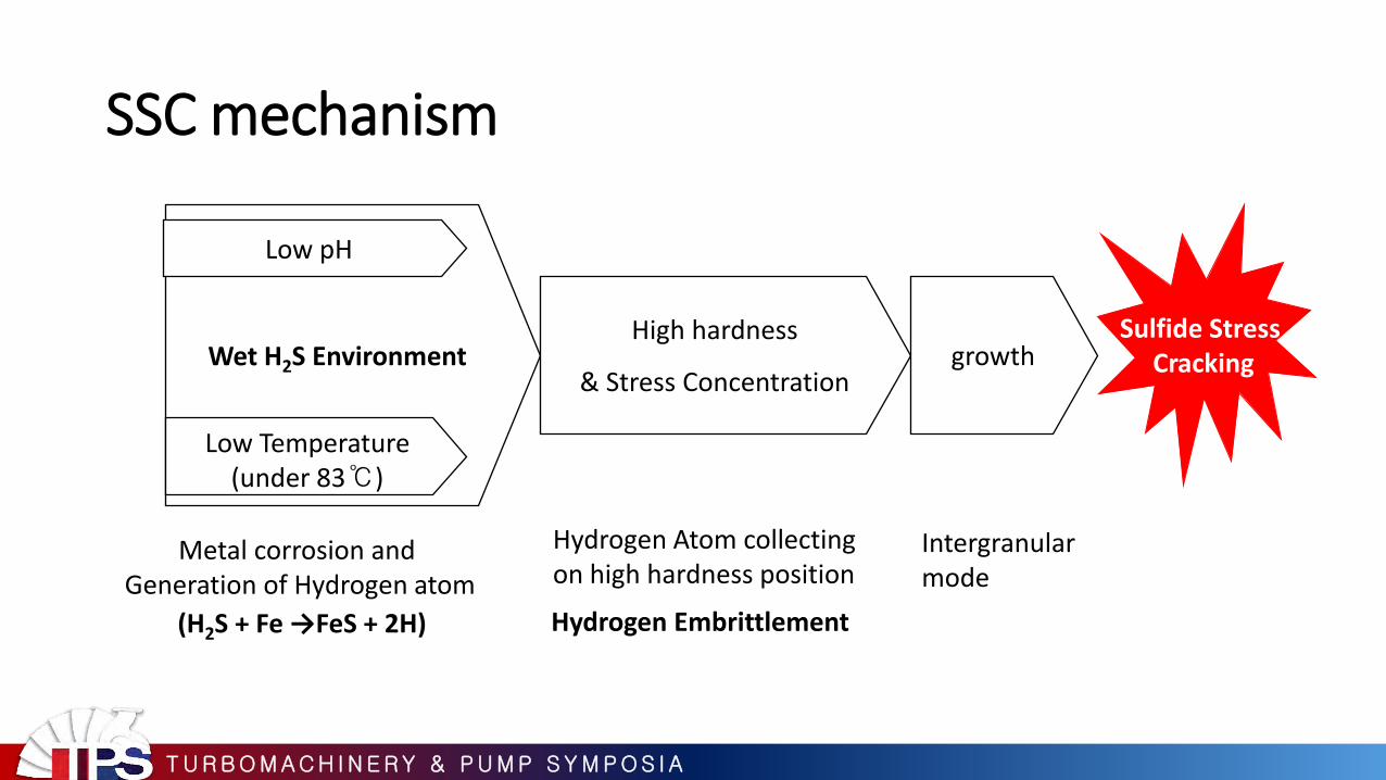
SSC mechanism
Wet H2S Environment
Low Temperature (under 83℃)
Low pH
High hardness
& Stress Concentration
Metal corrosion and Generation of Hydrogen atom
Hydrogen Atom collecting on high hardness position
(H2S + Fe →FeS + 2H) Hydrogen Embrittlement
Sulfide Stress Cracking growth
Intergranular mode

T U R B O M A C H I N E R Y & P U M P S Y M P O S I A
Recommendations
Impeller Type
Material Selection
Design
• High alloy steel selection to improve the corrosion resistance
• Material selection according to NACE MR0103 for Wet H2S environment (Hardness)
• To avoid high stress concentration on Impeller, better to use keyless assembling
Impeller assembling
• Because SSC is susceptible around Weld and HAZ, recommended to apply weldless impeller
If the process contains H2S and H2O (Wet H2S) even small amount,

T U R B O M A C H I N E R Y & P U M P S Y M P O S I A
Recommendations
Maintena-nce
• Recommended the periodical hardness check for internal wet parts of the equipment and vickers portable hardness measurement would be effective.
• Recommended periodical Non-destructive examination to verify hidden cracks underneath the metal surface for internal wet parts and WFMT (Wet Fluorescent Magnetic Particle Test) will be effective to verify cracks
Inspection
Hardness verification
If the process contains H2S and H2O (Wet H2S) even small amount,

T U R B O M A C H I N E R Y & P U M P S Y M P O S I A
End of document

T U R B O M A C H I N E R Y & P U M P S Y M P O S I A
Thanks and Questions
ACKNOWLEDGEMENTS This work has been encouraged by the Korea Rotating Machinery Engineers Association,(KRMEA). The authors are grateful for the encouragement

T U R B O M A C H I N E R Y & P U M P S Y M P O S I A
Appendix : Step of Sulfide Stress Cracking Step1. Surface corrosion : Generation of Hydrogen
𝐹 ↔ 𝐹𝑒2+ + 2𝑒
𝐻2𝑆 + 𝐻2𝑂 ↔ 𝐻+ + 𝐻𝑆− + 𝐻2𝑂
𝐻𝑆+ + 𝐻2𝑂 ↔ 𝐻+ + 𝑆− + 𝐻2𝑂
2𝑒 + 2𝐻+ + 𝐹𝑒2+ + 𝑆− ↔ 2𝐻0 + 𝐹𝑒𝑆
𝐹𝑒 + 𝐻2𝑆 ↔ 𝐹𝑒𝑆 + 2𝐻0
At the anode
At the cathode
Product Combination
Net reaction
anode
Cathode
• More H2S concentration, more generation of hydrogen atom • More susceptible at atmospheric temperature or below 82℃

T U R B O M A C H I N E R Y & P U M P S Y M P O S I A
Appendix : Step of Sulfide Stress Cracking Step2. Hydrogen atom diffusion
Hydrogen which is generated from corrosion reaction can diffuse to metal matrix because it is the smallest atom. Most of hydrogen atom is passed through metal matrix.
• Lower pH, higher diffusion rate : due to reduced recombination of hydrogen ion

T U R B O M A C H I N E R Y & P U M P S Y M P O S I A
Appendix : Step of Sulfide Stress Cracking Step3. Hydrogen atom collecting : Embrittlement
High Hardness area = High residual stress = Many of defects and dislocation (distortion of micro structure) ※ Normally hundreds millions of defects and dislocations is in a cubic centimeter of metal
H
H
H
H
H H
Low
High
defects dislocations
Hardness Defects and dislocation - Interrupt the diffusion of hydrogen atom - Hydrogen atom is collected and trapped in high
hardness area
As a result metal is more stressed by hydrogen atom and becoming more embrittled

T U R B O M A C H I N E R Y & P U M P S Y M P O S I A
Appendix : Step of Sulfide Stress Cracking Step4. Propagation of crack
Inter-granular crack
Trans-granular crack
vs
• Most of defects and dislocations in the metal is located around grain boundary. So grain boundary is more embrittled as more hydrogen atom collected.
• As a result, the crack from sulfide stress cracking mechanism is propagated along with grain boundary.

T U R B O M A C H I N E R Y & P U M P S Y M P O S I A
Appendix. SSC Threshold
API Limit Zone (Failure Free Zone)
Possible Zone
Case 1 material hardness
• For AISI4140 • Test result in the condition of H2O+H2S 40℃, 250 psi

T U R B O M A C H I N E R Y & P U M P S Y M P O S I A
Appendix. H2S Damages
SSC Blistering HIC
As NACE standard (ex. under 200HB for C.S.)
No effect Hardness
Possible to reduce No effect PWHT
Weld & HAZ All where discontinuity like micro
Fissure Location
MT(PT), UT UT Inspection
More appearance as H2S amount increases H2S amount

T U R B O M A C H I N E R Y & P U M P S Y M P O S I A
Appendix. Hydrogen embrittlement
Factor
Damage
High
Temperature
Low
Temperature
High
hydrogen
partial
pressure
Wet
H2S Hardness
Non-metal
filers Stress
High Temperature Hydrogen Attack ◈ ◈
Hydrogen Assisted Crack ◈ ◈ ◈ ◈
Hydrogen Embrittlement ◈ ◈ ◈ ◈
Sulfide Stress Corrosion Crack ◈ ◈ ◈ ◈
Hydrogen Induced Crack ◈ ◈ ◈
Delayed Crack ◈ ◈ ◈

T U R B O M A C H I N E R Y & P U M P S Y M P O S I A
Appendix. Factory history review for Case2
Raw Material
1st Machining
Welding
Heat Treatment
Inspection
Final Machining
Repair Welding
Heat Treatment
defect
1040℃
Solution treatment
32℃
+ 620℃, 4hr
Age-Hardening
620℃, 4hr
NACE Standard for 17-4PH
Actual Heat treatment after repair
630℃

T U R B O M A C H I N E R Y & P U M P S Y M P O S I A
Appendix. Determined crack by WFMT

T U R B O M A C H I N E R Y & P U M P S Y M P O S I A
Appendix. Example of hardness verification procedure
Parts Impeller hardness
Inspection Point Shroud, Disk and tip
Method Vickers hardness measurement
By inspection division
Hardness should be measured 6 points per impeller
Shroud Disk
Point to measure on shroud
Point to measure on disk
Point to measure on tip
Reference drawing

T U R B O M A C H I N E R Y & P U M P S Y M P O S I A
Appendix. Example of inspection procedure Parts Surface crack inspection for rotor
Inspection Point Overall surface of rotor excluding the position of bearing, prove, thrust collar
Method Visual inspection By mechanical division
WFMT By inspection division
PT By inspection division
Because it’s impossible to inspect the internal surface of impeller in detail, impeller eye and tip applied the magnetic field are enough to inspect If applied WFMT. Magnetic field have to be eliminated and residual magnetic field have to be under 3 Gauss after WFMT
Thrust collar Shaft
Bearing & Prove position
Impeller Impeller eye Impeller tip Reference drawing