Embed Size (px)
Citation preview
1
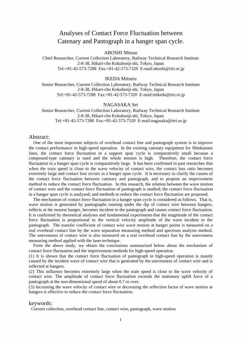
Analyses of Contact Force Fluctuation betweenCatenary and Pantograph in a hanger span cycle.
ABOSHI MitsuoChief Researcher, Current Collection Laboratory, Railway Technical Research Institute
2-8-38, Hikari-cho Kokubunji-shi, Tokyo, JapanTel:+81-42-573-7288 Fax:+81-42-573-7320 E-mail:[email protected]
IKEDA MitsuruSenior Researcher, Current Collection Laboratory, Railway Technical Research Institute
2-8-38, Hikari-cho Kokubunji-shi, Tokyo, JapanTel:+81-42-573-7288 Fax:+81-42-573-7320 E-mail:[email protected]
NAGASAKA SeiSenior Researcher, Current Collection Laboratory, Railway Technical Research Institute
2-8-38, Hikari-cho Kokubunji-shi, Tokyo, JapanTel:+81-42-573-7288 Fax:+81-42-573-7320 E-mail:[email protected]
Abstract:One of the most important subjects of overhead contact line and pantograph system is to improve
the contact performance in high-speed operation. In the existing catenary equipment for Shinkansenlines, the contact force fluctuation in a support span cycle is comparatively small because acompound-type catenary is used and the whole tension is high. Therefore, the contact forcefluctuation in a hanger span cycle is comparatively large. It has been confirmed in past researches thatwhen the train speed is close to the wave velocity of contact wire, the contact loss ratio becomesextremely large and contact loss occurs in a hanger span cycle. It is necessary to clarify the causes ofthe contact force fluctuation between catenary and pantograph, and to propose an improvementmethod to reduce the contact force fluctuation. In this research, the relation between the wave motionof contact wire and the contact force fluctuation of pantograph is studied; the contact force fluctuationin a hanger span cycle is analyzed; and methods to reduce the contact force fluctuation are proposed.
The mechanism of contact force fluctuation in a hanger span cycle is considered as follows. That is,wave motion is generated by pantographs running under the dip of contact wire between hangers,reflects at the nearest hanger, becomes incident to the pantograph and causes contact force fluctuation.It is confirmed by theoretical analyses and fundamental experiments that the magnitude of the contactforce fluctuation is proportional to the vertical velocity amplitude of the wave incident to thepantograph. The transfer coefficient of contact wire wave motion at hanger points is measured on areal overhead contact line by the wave separation measuring method and spectrum analysis method.The unevenness of contact wire is also measured on a real overhead contact line by the unevennessmeasuring method applied with the laser technique.
From the above study, we obtain the conclusions summarized below about the mechanism ofcontact force fluctuation and the improvement methods for high-speed operation.(1) It is shown that the contact force fluctuation of pantograph in high-speed operation is mainlycaused by the incident wave of contact wire that is generated by the unevenness of contact wire and isreflected at hangers.(2) This influence becomes extremely large when the train speed is close to the wave velocity ofcontact wire. The amplitude of contact force fluctuation exceeds the stationary uplift force of apantograph at the non-dimensional speed of about 0.7 or over.(3) Increasing the wave velocity of contact wire or decreasing the reflection factor of wave motion athangers is effective to reduce the contact force fluctuation.
keywords:Current collection, overhead contact line, contact wire, pantograph, wave motion
2
1. Introduction
For high-speed operation of electric railways, reducing the contact force fluctuation of pantograph isone of the most important subjects. It has been confirmed in past researches1) that when the trainspeed is close to the wave velocity of contact wire, the contact performance becomes extremelydegraded and contact loss occurs in a hanger span cycle. It is necessary to clarify the causes of thecontact force fluctuation between catenary and pantograph and propose an improvement method toreduce the contact force fluctuation.
In this paper, the relation between the wave motion of contact wire and the contact force fluctuationof pantograph is studied; the contact force fluctuation in a hanger span cycle is analyzed; and methodsto reduce the contact force fluctuation are proposed.
2. Contact force fluctuation
The best contact condition is that the contact force between contact wire and pantograph is alwaysconstant and equal to the stationary contact force. But the contact force changes in high-speedoperation due to several causes. The main causes are considered as (1) the fluctuation mechanism in asupport span cycle, (2) fluctuation mechanism in a hanger span cycle, (3) unevenness of contact wire(undulating wear, for example), (4) aerodynamic disturbance and others. The magnitude of thecontact force fluctuation in a support span cycle and that in a hanger span cycle are indices to evaluatethe dynamic performance of overhead equipment.
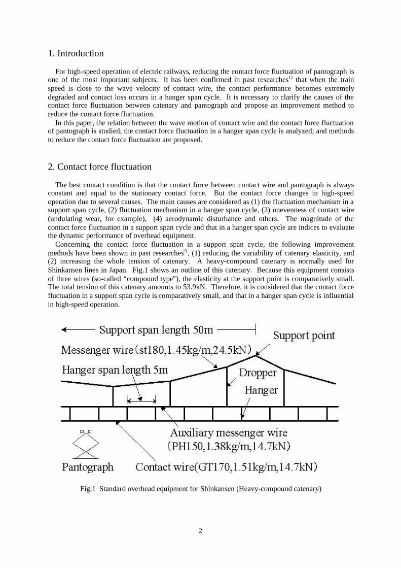
Concerning the contact force fluctuation in a support span cycle, the following improvementmethods have been shown in past researches2), (1) reducing the variability of catenary elasticity, and(2) increasing the whole tension of catenary. A heavy-compound catenary is normally used forShinkansen lines in Japan. Fig.1 shows an outline of this catenary. Because this equipment consistsof three wires (so-called “compound type”), the elasticity at the support point is comparatively small.The total tension of this catenary amounts to 53.9kN. Therefore, it is considered that the contact forcefluctuation in a support span cycle is comparatively small, and that in a hanger span cycle is influentialin high-speed operation.
Fig.1 Standard overhead equipment for Shinkansen (Heavy-compound catenary)

3
3. Analysis of contact wire wave motion
3.1 Method of measuring wave motions3)
The wave propagating velocity (phase velocity) of the contact wire is one of the most importantindices for the current collecting performance. The wave velocity is obtained by estimating thefrequency at which the addition or subtraction of accelerations at two points is equal to 0. Ameasurement example is shown in Fig.2. It is found that the wave velocity increases at highfrequencies because of its flexural rigidity and that the measured values agree well with the calculationresult.
In order to estimate the wave motion of the contact wire, it is necessary to separate the measuredvibration of the contact wire into the forward propagating wave and the backward one. If the wavemotion y(x,t) is expressed by Eq.(1), two wave motions propagating in opposite directions are obtainedby Eq.(2) by using the gradient and the wave velocity of the wire ct.
)()(),( tcxgtcxftxy tt ...........(1)
}),(
),({21
)(
}),(
),({2
1)(
dtx
txyctxytcxg
dtx
txyctxytcxf
tt
tt
...........(2)
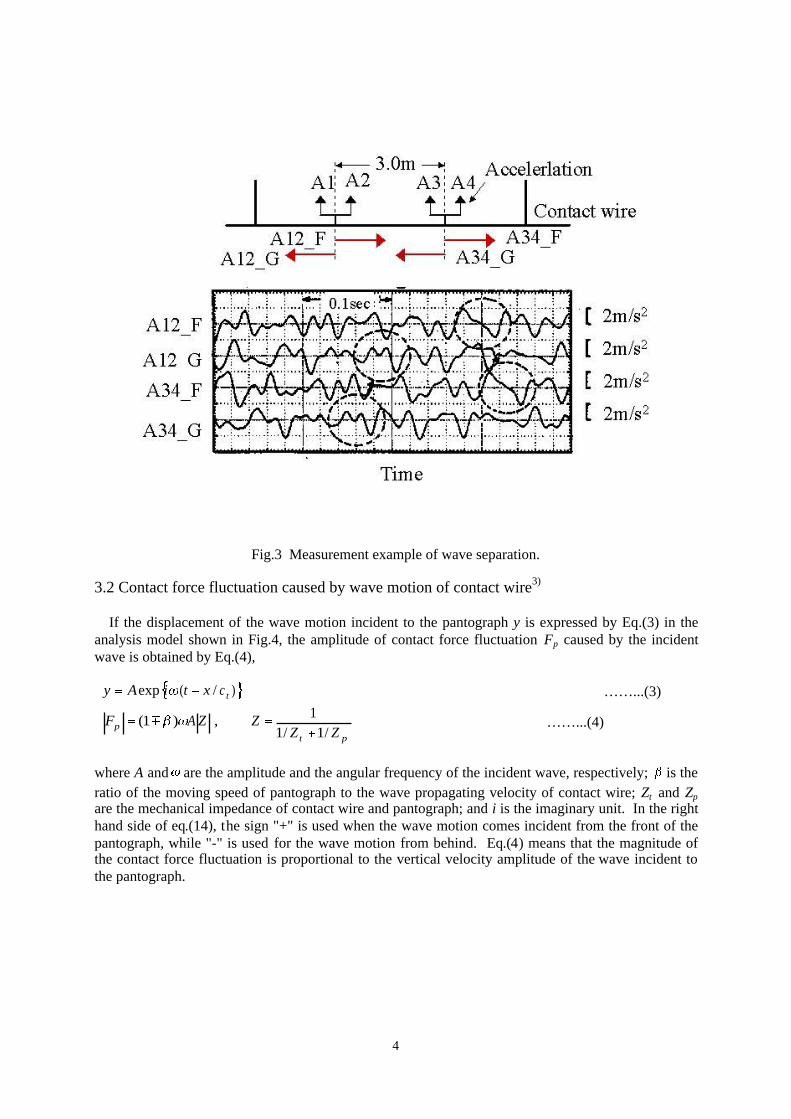
A measurement example of the wave separation is shown in Fig.3 (vertical acceleration limited under60Hz). The wave motions propagate on the contact wire in different directions (forward andbackward).
Fig.2 Measurement example of wave propagation velocity
4
Fig.3 Measurement example of wave separation.
3.2 Contact force fluctuation caused by wave motion of contact wire3)
If the displacement of the wave motion incident to the pantograph y is expressed by Eq.(3) in theanalysis model shown in Fig.4, the amplitude of contact force fluctuation Fp caused by the incidentwave is obtained by Eq.(4),
)/(exp tcxtiAy ……...(3)
ptp ZZ
ZZAF/1/1
1,)1( ……...(4)
where A and are the amplitude and the angular frequency of the incident wave, respectively; is theratio of the moving speed of pantograph to the wave propagating velocity of contact wire; Zt and Zp
are the mechanical impedance of contact wire and pantograph; and i is the imaginary unit. In the righthand side of eq.(14), the sign "+" is used when the wave motion comes incident from the front of thepantograph, while "-" is used for the wave motion from behind. Eq.(4) means that the magnitude ofthe contact force fluctuation is proportional to the vertical velocity amplitude of the wave incident tothe pantograph.

5
Fig.4 Analysis model for contact force fluctuation caused by wave motion of contact wire.
In order to verify the above-mentioned theoretical analysis, we measured the wave motion of thecontact wire incident to the pantograph and the contact force fluctuation at the same time4). An actualcatenary and pantograph are available for the experiment with the current collecting test equipment ofR.T.R.I. In order to measure the contact force, load-cells and accelerometers are set under the contactstrips of PS200A-type pantograph. A contact wire is only provided for the running experiment, inorder to simplify observation of the wave propagation.
The result of the experiment in rigid support is shown in Fig.5 (speed: 100km/h, =0.28)."V12_F"_"V34_G" indicate the vertical velocities of the wave motion passing through the measuringpoints (limited under 60Hz). It is found that the wave motion propagates forward (1)(2), reflects at theforward support point (3), comes incident to the pantograph (4), and repeats the reflection between thesupport point and the pantograph (5) ~(10). A large contact force fluctuation is caused when the wavemotion comes incident to the pantograph. The measuring results agree well with theoreticalcalculation.

6
Fig.5 Result of the fundamental experiment.
3.3 Generation of wave motion by unevenness of contact wire
As shown in Fig.6, we suppose that the contact wire is an infinite string which has the unevenness ofa wave length and one-side amplitude B. When a pantograph runs under the contact wire (speed,v), the amplitude of vertical velocity of the generated backward wave and forward wave |V1|, |V2| andthe angular frequency 21 , are obtained by Eq.(5) and Eq.(6). The contact force fluctuation causedby the unevenness of contact wire Fue is obtained by Eq.(7).

7
Fig.6 Analysis model for wave generation by unevenness of contact wire
0101 11,
11 B
ZZ
ZV
pt
p ……...(5)
0202 11,
11 B
ZZ
ZV
pt
p ……...(6)
tiBZZ
ZZiF
pt
ptue 00 exp .……..(7)
, where tc
vv ,20
These equations indicate that the frequency and the vertical velocity amplitude of the forward waveincreases when the pantograph speed becomes higher, and the forward wave is especially influential athigh-speed. Concerning the relation between the unevenness of contact wire and the amplitude ofgenerated wave motion, we have confirmed that the measurement results of fundamental experimentswith low spring constant hangers agree well with the theoretical analysis5).
3.4 Reflection of wave motion at hanger point
As shown in Fig.7, we suppose an analysis model in which two infinite strings are combined with aspring-damper element. The complex reflection factor R (the ratio of amplitude of reflected wave
A1r to that of incident wave A1i) is obtained by Eq.(8), where k, D, mt, and mm denote the springconstant, the damping factor and the mass of a hanger, respectively, while mtmt TT ,,, representthe line density and the tension of contact wire and messenger wire, respectively.

8
Fig.7 Analysis model for wave reflection at hanger.
ht
h
i
rR ZZ
Z
A
A
1
1 ……...(8)
ikDmiZ
miZ
mm
th
/11
1
Zt, and Zm are the mechanical impedance of contact wire and messenger wire, respectively, shown inEq.(9).
mmmttt TZTZ 2,2 ……...(9)
Fig.8 is an example of the transfer coefficients of contact wire at a hanger point (heavy-compoundcatenary; between contact wire and auxiliary messenger wire). These are calculated by taking intoconsideration the line flexural rigidity. These coefficients are measured on a real overhead contactline by the wave separation measuring method and spectrum analysis method6). It is confirmed thatthe measured values are mostly in agreement with theoretical values, and the line flexural rigidity isinfluential on the transfer coefficient even at low frequencies.

9
Fig.8 Coefficient of wave transfer at hanger.
4. Mechanism of contact force fluctuation in hanger span cycle
As shown in Fig.9, we suppose that the wave motion (1) is generated by the dip of contact wirebetween hangers, (2) reflects at the nearest hanger, (3) becomes incident to the pantograph and causesthe contact force fluctuation.
Fig.9 Analysis model for contact force fluctuation in a hanger span cycle.

10
The unevenness of contact wire is also measured on a real overhead contact line by the unevennessprecise measuring method applied with the laser technique7). Fig.10 shows a measurement example ofunevenness of contact wire of Shinkansen. The unevenness of wavelength =5m (wave number=0.2) is equivalent to the dip between hangers. The shorter wavelengths are also seen in thismeasurement result.
Fig.10 Measurement example of contact wire unevenness in Shinkansen.
If the dip between hangers is assumed to be a secondary curve, the k-th coefficient of Fourier seriesak is expressed by Eq.(10), where Lh is the span length between hangers.
0cos2
2
kkk
L
T
ga h
t
tk ..…...(10)
The amplitude of the k-th unevenness is 1/k2 times the primary unevenness, and its wavelength is1/k times. Therefore, it is shown from Eq.(6) that the vertical velocity amplitude of the contact wirewave motion generated by the k-th unevenness becomes 1/k times in the case of primary unevenness.In other words, the influence of the higher order unevenness of the dip between hangers on thegeneration of contact wire wave motion is comparatively small. If the contact wire unevenness can be regard as a first harmonic of the dip between hangers, theamplitude of contact wire unevenness B is simply expressed by Eq.(11).
2
212
h
t
L
c
gaB .........(11)
The vertical velocity amplitude and the angular frequency of the generated wave motion of contact

11
wire (forward wave) 22 ,V are obtained by Eq.(12), and the amplitude of the contact force
fluctuation caused only by the unevenness of contact wire |Fue| is obtained by Eq.(13).
h
t
t
h
pt
p
L
c
c
L
ZZ
ZgV
12
1
2
2
0 …….(12)
h
t
pt
phtue
L
c
ZZ
ZgLF
2
2
0
0 …….(13)
Fig.11 shows a measurement example on Shinkansen line in which the forward wave is generatedby the dip of contact wire between hangers and propagates in front of the pantograph. Under theconditions of =5m, ct= 114m/s, and v=61.1m/s (220km/h), the frequency of the generated wavemotion is calculated as 26Hz from Eq.(12). The frequency of the forward wave observed by thismeasurement is mostly in agreement with this calculated value. It is confirmed that the contact wirewave motion is also generated by the dip between hangers in actual equipment.
Fig.11 Example of wave generation by dip between hangers.
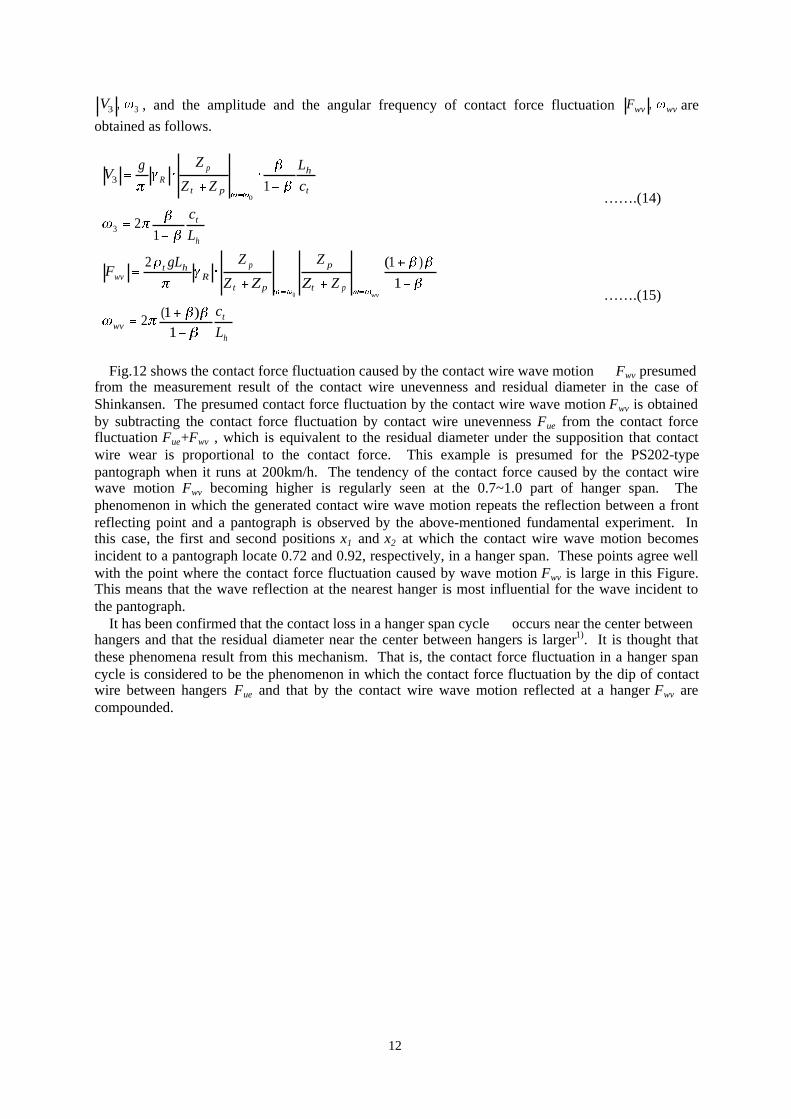
Next, if it is assumed that the forward wave motion reflects and returns R times at a hanger point,the vertical velocity amplitude and the angular frequency of the incident wave to a pantograph
12
33 ,V , and the amplitude and the angular frequency of contact force fluctuation wvwvF , are
obtained as follows.
h
t
t
h
pt
pR
L
c
c
L
ZZ
ZgV
12
1
3
3
0 …….(14)
h
twv
pt
p
pt
pR
htwv
L
c
ZZ
Z
ZZ
ZgLF
wv
1)1(2
1
)1(2
0 …….(15)
Fig.12 shows the contact force fluctuation caused by the contact wire wave motion Fwv presumedfrom the measurement result of the contact wire unevenness and residual diameter in the case ofShinkansen. The presumed contact force fluctuation by the contact wire wave motion Fwv is obtainedby subtracting the contact force fluctuation by contact wire unevenness Fue from the contact forcefluctuation Fue+Fwv , which is equivalent to the residual diameter under the supposition that contactwire wear is proportional to the contact force. This example is presumed for the PS202-typepantograph when it runs at 200km/h. The tendency of the contact force caused by the contact wirewave motion Fwv becoming higher is regularly seen at the 0.7~1.0 part of hanger span. Thephenomenon in which the generated contact wire wave motion repeats the reflection between a frontreflecting point and a pantograph is observed by the above-mentioned fundamental experiment. Inthis case, the first and second positions x1 and x2 at which the contact wire wave motion becomesincident to a pantograph locate 0.72 and 0.92, respectively, in a hanger span. These points agree wellwith the point where the contact force fluctuation caused by wave motion Fwv is large in this Figure.This means that the wave reflection at the nearest hanger is most influential for the wave incident tothe pantograph. It has been confirmed that the contact loss in a hanger span cycle occurs near the center betweenhangers and that the residual diameter near the center between hangers is larger1). It is thought thatthese phenomena result from this mechanism. That is, the contact force fluctuation in a hanger spancycle is considered to be the phenomenon in which the contact force fluctuation by the dip of contactwire between hangers Fue and that by the contact wire wave motion reflected at a hanger Fwv arecompounded.

13
Fig.12 Contact force fluctuation by wave motion presumed from measured unevenness and residualdiameter.
5. Contact force fluctuation in high-speed operation
5.1 Speed characteristic of contact force fluctuation in a hanger span cycle
Fig.13 shows an example of the amplitude of contact force fluctuation | Fue| and | Fwv| which iscalculated by Eq.(13) and Eq.(15). These curves show the characteristics of non-dimensional speed inthe condition of heavy-compound catenary and Zp>>Zt. The contact force fluctuation caused bycontact wire unevenness |Fue| increases linearly with speed. On the other hand, when exceeds about
0.7, the contact force fluctuation caused by the reflective wave motion |Fwv| increases remarkably.This characteristic is based on the so-called Doppler effect as shown in Eq.(15). Consequently, it isshown that the influence of wave reflection becomes larger especially in high-speed operation. This characteristic of contact force fluctuation agrees well with the radically increasing tendency ofcontact loss ratio. Therefore, we think that the phenomenon, in which the contact loss ratio increasesremarkably as the running speed approaches the wave propagation velocity of contact wire, is mainlybased on the contact force fluctuation in a hanger span cycle. The amplitude of contact force fluctuation caused by the reflective wave motion | Fwv| is comparedand shown in Fig.14 for the case of heavy-compound (HC) catenary and the case of high-tensionheavy-compound (HTHC) catenary for which the tension of contact wire is increased to 19.6kN. Inthis case, these values are calculated with the parameter of PS202 pantograph. In the case of high-tension heavy-compound catenary, the wave propagation velocity of contact wire is about 15% higher,and the reduction effect of contact force fluctuation by decreasing is seen. Fig.15 shows the
comparison of these cases at non-dimensional speed , and it is found that these characteristics havealmost the same curves. As shown in Eq.(15), this is because the amplitude of the contact force

14
fluctuation |Fwv| mainly depends on the non-dimensional speed if the contact wire is the same type andthe reflective coefficient is the same.
Fig.13 Calculated example of contact force fluctuation
Fig.14 Comparison of contact force fluctuation

15
Fig.15 Comparison of contact force fluctuation (non-dimensional speed)
By using Fig.14, we will estimate here the maximum speed without contact loss. We suppose thatthe stationary uplift force of the moving pantograph is 74N (static uplift force 54N + aerodynamicuplift force 20N) and contact loss will occur when the amplitude of contact force fluctuation caused bywave motion reflection of contact wire exceeds the stationary uplift force. In regard to the speeddependence in this Figure, it is indicated that the maximum speed without contact loss (critical speed)is about 270km/h for the heavy-compound catenary, and 320km/h for the high-tension heavy-compound catenary. In the actual case, it is thought that contact loss occurs below these speedsbecause of other causes. However, the speed shown here becomes the standard value for themaximum operation speed as a contact performance index of overhead equipment. The high-tensionheavy-compound catenary is one of the standard types for 300km/h high-speed operation in Japan.
5.2 Improvement methods of catenary for high-speed operation
Based on Eq.(15), improvement methods for high-speed operation are shown as follows.(1) Increasing the wave propagation velocity of contact wire.(2) Decreasing the density of contact wire.(3) Reducing the wave reflection of contact wire.(4) Shortening the hanger span length.
The present overhead equipment of Shinkansen for 300km/h operation has a high wave propagationvelocity of contact wire by increasing the tension of contact wire, and adoption of lightweight contactwire. This is desirable from the viewpoint of this research. Moreover, if it has the same wavepropagation velocity, the smaller the line density of contact wire is, the better the performance is.
In order to reduce the reflection of contact wire wave motion at a hanger point, use of hangerswhich have a spring and a damper mechanism is effective. Although the use of these damping typehangers cannot remarkably change the increasing tendency of contact loss depending on the relationbetween the train speed and the wave propagation velocity of contact wire, these hangers are expected

16
to reduce the contact force fluctuation below the critical speed. The reflection factor of wave motionwith a damping hanger will be calculated as shown in Fig.16. A coil spring is used in the frictiondamping hanger, and a piece of rubber is used in the rubber damping hanger. From the results of thefield test carried out on Sanyo Shinkansen line, it is found that there is a close correlation between thecontact loss ratio and the vertical velocity of backward wave motion8). The rubber damping hangerscan reduce the magnitude of the wave motion incident to the pantograph and the contact loss ratio.
Fig.16 Reflection factor of wave motion at hanger.
The measurement results for Shinkansen lines show that the contact loss ratio in the section of a3.5m-long hanger span is smaller than that in the section of 5m-long one. We think that our theorycan explains such measurement results.
6. Conclusion
In the existing catenary equipment for Shinkansen lines, the contact force fluctuation in a supportspan cycle is comparatively small because it is a compound type and the whole tension is higher.Therefore, the contact force fluctuation in a hanger span cycle is comparatively large. From the abovestudy, we have obtained the conclusions summarized below about the mechanism of contact forcefluctuation and improvement methods for high-speed operation.(1) It is shown that the contact force fluctuation of pantograph in high-speed operation is mainlycaused by the incident wave of contact wire that is generated by the unevenness of contact wire and isreflected at hangers.(2) This influence becomes extremely large when the train speed is close to the wave velocity ofcontact wire. The amplitude of contact force fluctuation exceeds the stationary uplift force of apantograph at the non-dimensional speed of about 0.7 or over.(3) Increasing the wave velocity of contact wire or decreasing the reflection factor of wave motion athangers effectively reduces the contact force fluctuation.

17
References(1) Manabe, K.: ”High-speed contact performance of catenary -pantograph system”, JSME, Vol.54,No.504, pp.1843-1851, 1988(2) G. Gilbert,: ”Pantograph motion on a nearly uniform railway overhead line”, PROC.IEE, Vol.113,No3, 1966(3) Aboshi, M.: “Research for contact loss reduction method by damping catenary vibration”,WCRR’97, Vol.C, pp.151-159, 1997(4) Aboshi, M.: ”Influence of wave motion of contact wire on contact force fluctuation (1st report,theoretical analysis and fundamental experiments)”, JSME, Vol.63, No.614, pp.90-96, 1997(5) Aboshi, M.: ”Relation between wave motion and unevenness of contact wire”, JSME, D&D’98,1998(6) Aboshi, M.: ”Transfer characteristics of contact line wave at hanger point”, JSME, No.00-50,pp.259-262, 2000(7) Aboshi, M.: ”Measurement and its estimation method of contact wire unevenness”, RTRI Report,Vol.15, No.6, pp.45-50, 2001(8) Aboshi, M.: ”Influence of wave motion of contact wire on contact force fluctuation (2nd report,experiments in practical catenary-pantograph system)”, JSME, Vol.64, No.622, pp.30-37, 1998