Embed Size (px)
Citation preview

ANALOGUE ADDRESSABLEFIRE PANEL
INSTALLATION AND PROGRAMMING MANUAL
2 Addressable Fire Panel IRIS - Installation and Programming Manual
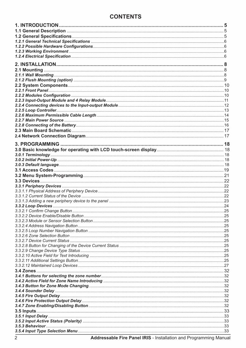
CONTENTS1. INTRODUCTION ....................................................................................................................... 51.1 General Description ............................................................................................................................51.2 General Specifications ........................................................................................................................51.2.1 General Technical Specifications ....................................................................................................................61.2.2 Possible Hardware Configurations ..................................................................................................................61.2.3 Working Environment .......................................................................................................................................61.2.4 Electrical Specification .....................................................................................................................................6
2. INSTALLATION ......................................................................................................................... 82.1 Mounting ..............................................................................................................................................82.1.1 Wall Mounting ....................................................................................................................................................82.1.2 Flush Mounting (option) ...................................................................................................................................92.2 System Components ...........................................................................................................................102.2.1 Front Panel .........................................................................................................................................................102.2.2 Modules Configuration .....................................................................................................................................102.2.3 Input-Output Module and 4 Relay Module .......................................................................................................112.2.4 Connecting devices to the Input-output Module ............................................................................................122.2.5 Loop Controller ..................................................................................................................................................132.2.6 Maximum Permissible Cable Length ...............................................................................................................142.2.7 Main Power Source ...........................................................................................................................................152.2.8 Connecting of the Battery .................................................................................................................................162.3 Main Board Schematic ........................................................................................................................172.4 Network Connection Diagram ............................................................................................................. 17
3. PROGRAMMING ...................................................................................................................... 183.0 Basic knowledge for operating with LCD touch-screen display..................................................... 18 3.0.1 Terminology .......................................................................................................................................................183.0.2 Initial Power-Up .................................................................................................................................................183.0.3 Default language................................................................................................................................................183.1 Access Codes ......................................................................................................................................193.2 Menu System-Programming ............................................................................................................... 213.3 Devices ................................................................................................................................................. 223.3.1 Periphery Devices .............................................................................................................................................223.3.1.1 Physical Address of Periphery Device ..............................................................................................................223.3.1.2 Current Status of the Device ............................................................................................................................223.3.1.3 Adding a new periphery device to the panel ....................................................................................................233.3.2 Loop Devices .....................................................................................................................................................243.3.2.1 Confirm Change Button ....................................................................................................................................253.3.2.2 Device Enable/Disable Button ..........................................................................................................................253.3.2.3 Module or Sensor Selection Button ..................................................................................................................253.3.2.4 Address Navigation Button ...............................................................................................................................253.3.2.5 Loop Number Navigation Button ......................................................................................................................253.3.2.6 Zone Selection Button ......................................................................................................................................253.3.2.7 Device Current Status ......................................................................................................................................253.3.2.8 Button for Changing of the Device Current Status ...........................................................................................253.3.2.9 Change Device Type Status .............................................................................................................................253.3.2.10 Active Field for Text Introducing .....................................................................................................................253.3.2.11 Additional Settings Button ...............................................................................................................................253.3.2.12 Maintained Loop Devices ...............................................................................................................................273.4 Zones .................................................................................................................................................... 323.4.1 Buttons for selecting the zone number ...........................................................................................................323.4.2 Active Field for Zone Name Introducing .........................................................................................................323.4.3 Button for Zone Mode Changing ......................................................................................................................323.4.4 Sounder Delay ...................................................................................................................................................323.4.5 Fire Output Delay...............................................................................................................................................323.4.6 Fire Protection Output Delay ............................................................................................................................323.4.7 Zone Enabling/Disabling Button ......................................................................................................................323.5 Inputs .................................................................................................................................................... 333.5.1 Input Delay .........................................................................................................................................................333.5.2 Input Active Status (Polarity) ...........................................................................................................................333.5.3 Behaviour ...........................................................................................................................................................333.5.4 Input Type Selection Menu ...............................................................................................................................33

Addressable Fire Panel IRIS - Installation and Programming Manual 3
3.5.5 Input Parameters Selection Menu ....................................................................................................................333.6 Outputs ................................................................................................................................................. 353.6.1 Output Type Selection Menu ............................................................................................................................353.6.2 Output Parameters Selection Menu .................................................................................................................353.6.3 Output Delay ......................................................................................................................................................353.6.4 Output Active Status (Polarity) ........................................................................................................................353.6.5 Output Pulse Type .............................................................................................................................................353.6.6 Behaviour ...........................................................................................................................................................363.6.7 Menu for selection of the inputs, controlling the outputs .............................................................................363.7 Panel .....................................................................................................................................................373.7.1 Changing Access Code and Level ...................................................................................................................373.7.2 Network ..............................................................................................................................................................383.7.2.1 Network Parameters Setting.............................................................................................................................383.7.2.2 Panels Menu.....................................................................................................................................................393.7.3 Earth Fault ..........................................................................................................................................................403.7.4 Sounders Mode..................................................................................................................................................403.7.5 Call Points Mode................................................................................................................................................413.7.6 Language Setting ..............................................................................................................................................41
4. MAINTENANCE ........................................................................................................................ 424.1 Menu System-Maintenace................................................................................................................... 42 4.2 Time Setting ......................................................................................................................................... 42 4.3 Date Setting.......................................................................................................................................... 424.4 Daytime Mode ...................................................................................................................................... 434.5 Outputs Delay Introducing ................................................................................................................. 444.5.1 Sounder Delay ...................................................................................................................................................444.5.2 Fire Output Delay...............................................................................................................................................454.5.3 Fire Protection Output Delay ............................................................................................................................454.6 LOG-File Viewing ................................................................................................................................. 454.7 Testing .................................................................................................................................................. 464.8 Disabling .............................................................................................................................................. 464.8.1 Loop Devices Disabling ....................................................................................................................................474.8.2 Zones Disabling .................................................................................................................................................474.8.3 Outputs Disabling ..............................................................................................................................................484.9 Software Version ................................................................................................................................. 484.10 Display ................................................................................................................................................484.10.1 Display Calibration ..........................................................................................................................................494.10.2 Colours Calibration .........................................................................................................................................504.10.3 Power Save Backlight Mode ...........................................................................................................................50
5. USER INSTRUCTIONS ............................................................................................................. 515.1 Status Line ...........................................................................................................................................515.1.1 Change of Access Level Button .......................................................................................................................515.1.2 Quick Access to the Functional Buttons ........................................................................................................515.1.3 Quick Access to the Alarm Messages .............................................................................................................515.1.4 Quick Access to the Fault Messages ..............................................................................................................515.1.5 Quick Access to the Warning Messages .........................................................................................................515.2 Panel Status Icons............................................................................................................................... 525.2.1 Panel Mode Icon ................................................................................................................................................525.2.2 Sounders Status Icon........................................................................................................................................525.2.3 Fire Output Status Icon .....................................................................................................................................525.2.4 Fire Protection Output Status Icon ..................................................................................................................525.3 Messages .............................................................................................................................................535.4 Access Level ........................................................................................................................................535.5 Main Screen ......................................................................................................................................... 535.5.1 Silence Buzzer Button.......................................................................................................................................535.5.2 Reset Button ......................................................................................................................................................535.5.3 Relay Override Button.......................................................................................................................................535.5.4 Silence Alarm Button ........................................................................................................................................535.5.5 Evacuate Button ................................................................................................................................................53
6. APPENDIx ................................................................................................................................ 54

4 Addressable Fire Panel IRIS - Installation and Programming Manual
GuaranteeDuring the guarantee period the manufacturer shall, at its sole discretion, replace or repair any defective product when it is returned to the factory. All parts replaced and/or repaired shall be covered for the remainder of the original guaran-tee, or for ninety (90) days, whichever period is longer. The original purchaser shall immediately send manufacturer a written notice of the defective parts or workmanship, which written notice must in all cases be received prior to expiry of the guarantee.International GuaranteeForeign customers shall enjoy the same guarantee rights as those enjoyed by any customer in Bulgaria, except that manufacturer shall not be liable for any related customs duties, taxes or VAT, which may be payable.Guarantee ProcedureThis guarantee will be granted when the appliance in question is returned. The manufacturer shall accept no product whatsoever, of which no prior notice has been received.Conditions for waiving the guaranteeThis guarantee shall apply to defects in products resulting only from improper materials or workmanship, related to its normal use. It shall not cover:• Damages resulting from transportation and handling;• Damages caused by natural calamities, such as fire, floods, storms, earthquakes or lightning;• Damages caused by incorrect voltage, accidental breakage or water; beyond the control of the manufacturer;• Damages caused by unauthorized system incorporation, changes, modifications or surrounding objects:• Damages caused by peripheral appliances (unless such peripheral appliances have been supplied by theManufacturer:• Defects caused by inappropriate surrounding of installed products;• Damages caused by failure to use the product for its normal purpose; • Damages caused by improper maintenance;• Damages resulting from any other cause, bad maintenance or product misuse.In the case of a reasonable number of unsuccessful attempts to repair the product, covered by this guarantee, theManufacturer’s liability shall be limited to the replacement of the product as the sole compensation for breach of the guarantee. Under no circumstances shall the manufacturer be liable for any special, accidental or consequential dam-ages, on the grounds of breach of guarantee, breach of agreement, negligence, or any other legal notion.WaiverThis Guarantee shall contain the entire guarantee and shall be prevailing over any and all other guarantees, explicit or implicit (including any implicit guarantees on behalf of the dealer, or adaptability to specific purposes), and over any other responsibilities or liabilities on behalf of the manufacturer. The manufacturer does neither agree, nor empower, any person, acting on his own behalf, to modify or alter this Guarantee, nor to replace it with another guarantee, or another liability with regard to this product.Unwarranted ServicesThe manufacturer shall repair or replace unwarranted products, which have been returned to its factory, at its sole discretion under the conditions below. The manufacturer shall accept no products for which no prior notice has been received.The products, which the manufacturer deems repairable, will be repaired and returned. The manufacturer has prepared a price list and those products, which can be repaired, shall be paid for every repaired appliance.The closest equivalent product, available at the time, shall replace the products manufacturer deems unrepeatable.The current market price shall be charged for every replaced product.
ATTENTION!This manual contains an information about the limitations in using and operation of the product, as and infor-mation about the limits in the responsibility of the manufacturer. Please read the operation manual carefully before starting the installation.
While every effort has been made to ensure that the information in this manual is accurate and complete, no liability can be accepted for any errors or omissions.The manufacturer reserves the right to change the specifications of the equipment described in that manual without notice.
!

Addressable Fire Panel IRIS - Installation and Programming Manual 5
1. INTRODUCTION
1.1 General DescriptionIRIS is an analogue addressable fire panel with maximum coverage of 96 zones and connecting 1 to 4 loops. The panel supports two communication protocols: System Sensor series 200/500 (Loop SS) and Teletek Electronics (Loop TTE) according the type of used devices. In the configuration of the IRIS panel can be implemented both Loops SS and TTE at the same time. An arbitrary number of devices can be added to each zone thus ensuring the easy adaptation of the system to any type of configuration.To avoid or significantly diminish problems when mounting the system it must be carefully planned prior to installation. This includes: establishing an address for every device and planning a name of maximum 40 digits (including the spaces) for each address, thereby ensuring easy access to the device.According to the acting standards for establishing fire systems and the plan of the building, the devices must be grouped in zones.
Every Loop SS provides up to 99 detectors and 99 modules - “IRIS” Solution.
Every Loop TTE provides up to 250 devices (detectors and modules, regardless of the type) - “IRIS light” Solution.
General view of the IRIS Fire Panel
1.2 General SpecificationsThe front panel consists of color graphic LCD display (dimensions 240x320) with a built-in touch screen and a light-emitting diode indication. Separate operator and engineer passwords provide access to the functions of the panel. The internal space of the box is protected with the help of secret screws.Up to four loop controllers, Loop SS and Loop TTE, can be supplemented to the mother board. The system can be expanded by connecting several fire panels IRIS to the Ethernet, using TCP/IP for communication between them.The panel has a built-in real time clock and calendar, allowing day and night time modes of work.Switching over between the two modes can be automatic or manual. Events like FIRE, RESET, FAULT, etc., are saved in the memory, thereby creating an event log-file. It contains the time and date, the address of the device, the type (module or detector), the name of the device, the zone, the name of the zone, etc.
!
6 Addressable Fire Panel IRIS - Installation and Programming Manual
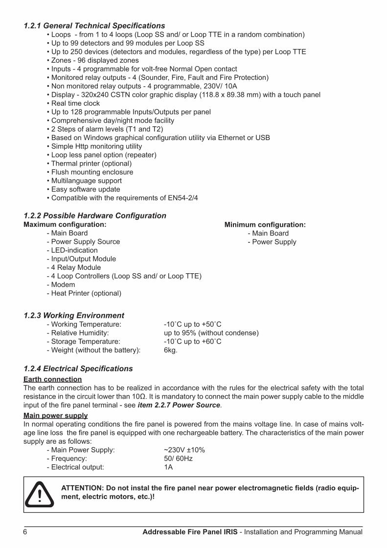
1.2.1 General Technical Specifications • Loops - from 1 to 4 loops (Loop SS and/ or Loop TTE in a random combination) • Up to 99 detectors and 99 modules per Loop SS • Up to 250 devices (detectors and modules, regardless of the type) per Loop TTE • Zones - 96 displayed zones • Inputs - 4 programmable for volt-free Normal Open contact • Monitored relay outputs - 4 (Sounder, Fire, Fault and Fire Protection) • Non monitored relay outputs - 4 programmable, 230V/ 10A • Display - 320x240 CSTN color graphic display (118.8 x 89.38 mm) with a touch panel • Real time clock • Up to 128 programmable Inputs/Outputs per panel • Comprehensive day/night mode facility • 2 Steps of alarm levels (T1 and T2) • Based on Windows graphical configuration utility via Ethernet or USB • Simple Http monitoring utility • Loop less panel option (repeater) • Thermal printer (optional) • Flush mounting enclosure • Multilanguage support • Easy software update • Compatible with the requirements of EN54-2/4
1.2.2 Possible Hardware ConfigurationMaximum configuration: - Main Board - Power Supply Source - LED-indication - Input/Output Module - 4 Relay Module - 4 Loop Controllers (Loop SS and/ or Loop TTE) - Modem - Heat Printer (optional)
1.2.3 Working Environment - Working Temperature: -10˚C up to +50˚C - Relative Humidity: up to 95% (without condense) - Storage Temperature: -10˚C up to +60˚C - Weight (without the battery): 6kg.
1.2.4 Electrical SpecificationsEarth connectionThe earth connection has to be realized in accordance with the rules for the electrical safety with the total resistance in the circuit lower than 10Ω. It is mandatory to connect the main power supply cable to the middle input of the fire panel terminal - see item 2.2.7 Power Source. Main power supplyIn normal operating conditions the fire panel is powered from the mains voltage line. In case of mains volt-age line loss the fire panel is equipped with one rechargeable battery. The characteristics of the main power supply are as follows: - Main Power Supply: ~230V ±10% - Frequency: 50/ 60Hz - Electrical output: 1A
ATTENTION: Do not instal the fire panel near power electromagnetic fields (radio equip-ment, electric motors, etc.)!
Minimum configuration: - Main Board - Power Supply
!

Addressable Fire Panel IRIS - Installation and Programming Manual 7
Battery Power Supply - Voltage output (U): 13,8V - Current output (I): 2A - Number of the Batteries: 1, 12V/ 18Ah - Battery Size: 167x181x76mm - Type of the Battery connection: with a flat terminal lug - Ø5mm (M5)
List of the fuses - General Power Supply: 2A, T Type - Outputs: 0,3A, PTC Type - Battery: 7.5A, PTC Type
List of the additional components, included in the set of the fire panel IRIS:
1. Resistor 10K ±5%, 0,25W 2
2. Anchor 6х30mm 4
3. Fuse 2А, T type 5x20mm (for the mains power supply) 1
4. Screw М4х40 Cross slot DIN7985 4
5. Screw М4х30 Cross slot DIN965 2
6. Screw М4,2х35 Cross slot DIN7981 4
7. Washer М4 DIN522 4
8. Cable tie 2,5/160mm 2
9. Plastic cap 21
The panel should be installed by qualified specialists only.The electronic components of the panel are vulnerable to electrostatic discharge.Never add or turn off components which are being power supplied!!

8 Addressable Fire Panel IRIS - Installation and Programming Manual
2. INSTALLATION2.1 Mounting• The panel must be installed in a clean dry place and must not be subjected to impact or vibrations (Figure 1). It must be situated far form heating appliances. The temperature must be within -5ºС and + 50ºC. The fire panel is not water-proof! • Unscrew the two secret bolts situated above and under the box cover - see Figure 2.• Remove the front cover as first disconnect the flat-cable for panel indication. After that unscrew the hinge bolts on the side of the front panel - Figure 3. (Note: You can unscrew and the hinge bolts on the side of the metal box. The special here is the presence of two plastic pads situated under the hinges. The pads have to be returned back under the hinges at closing the front cover.) • Choose inlets for the cables, and put plastic taps on those ones which you will not use.
Figure 1 Figure 2 Figure 3
2.1.1 Wall Mounting• Use the template in the set to fix the mounting holes of the metal box on the wall - see Figure 4.• Drill holes (suitable for anchors Ø6mm) on the wall and fix the metal box - see Fig 5.• Route the external cables onto the back box, make off connection glands etc., BUT DO NOT make any con-nections at this stage. ENTER THE MAINS CABLE THROUGH ITS OWN CABLE ENTRY POINT AND KEEP MAINS WIRING AWAY FROM SYSTEM AND OTHER LOW VOLTAGE WIRING.• Connect the mains supply and earth to the power sup-ply terminal (see Figure 17) BUT DO NOT apply the main electrical supply at this stage.• Position the battery in an upright position and fix the metal clamp - Figure 10.
Figure 4 Figure 5
Addressable Fire Panel IRIS - Installation and Programming Manual 9
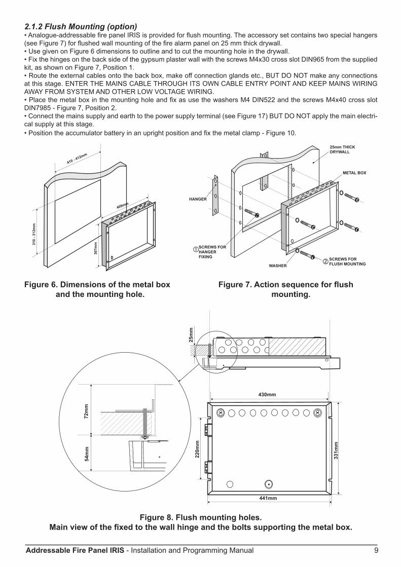
2.1.2 Flush Mounting (option)• Analogue-addressable fire panel IRIS is provided for flush mounting. The accessory set contains two special hangers (see Figure 7) for flushed wall mounting of the fire alarm panel on 25 mm thick drywall.• Use given on Figure 6 dimensions to outline and to cut the mounting hole in the drywall.• Fix the hinges on the back side of the gypsum plaster wall with the screws M4x30 cross slot DIN965 from the supplied kit, as shown on Figure 7, Position 1. • Route the external cables onto the back box, make off connection glands etc., BUT DO NOT make any connections at this stage. ENTER THE MAINS CABLE THROUGH ITS OWN CABLE ENTRY POINT AND KEEP MAINS WIRING AWAY FROM SYSTEM AND OTHER LOW VOLTAGE WIRING.• Place the metal box in the mounting hole and fix as use the washers M4 DIN522 and the screws M4x40 cross slot DIN7985 - Figure 7, Position 2.• Connect the mains supply and earth to the power supply terminal (see Figure 17) BUT DO NOT apply the main electri-cal supply at this stage.• Position the accumulator battery in an upright position and fix the metal clamp - Figure 10.
Figure 6. Dimensions of the metal box Figure 7. Action sequence for flush and the mounting hole. mounting.
Figure 8. Flush mounting holes. Main view of the fixed to the wall hinge and the bolts supporting the metal box.
HANGER
SCREWS FORHANGER FIXING
SCREWS FORFLUSH MOUNTING
METAL BOX
25mm THICKDRYWALL
WASHER
HANGER
SCREWS FORHANGER FIxING
WASHERSCREWS FOR FLUSH MOUNTING
METAL BOx
25mm THICKDRYWALL

10 Addressable Fire Panel IRIS - Installation and Programming Manual
2.2 System components2.2.1 Front panel
Figure 9. Main view of the front panel.
2.2.2 Configuration of the basic modules
Figure 10. Configuration of the basic modules in the system.
LED-indication of the events provides following functions:GENERAL FIRE - General FIRE IndicationPREALARM - Indication for zones in Pre-Alarm Condi-tionGENERAL FAULT - General FAULT IndicationSYSTEM FAULT - General SYSTEM FAULT IndicationSYSTEM SILENCE - General Indication for Silenced SoundersDELAY - General Indication for Active Delay in any of the OutputsDISABLE - General Indication for introduced DisabilityTEST - General Indication for TestPOWER ON - Presence of mains power supply 230V AC
LED indicationfor the events
LED indicationfor the zones
Heat printer(option)
LCD Display(320x240)
Pow
er S
uppl
y U
nit
Loop Controller
1
Loop Controller
2
Loop Controller
3
Loop Controller
44 Relay Module
I/O Module
AccumulatorBattery
12V / 18 Ah
Clamp for supporting the main power
supply cable.
Clamp for supporting the main power
supply cable.
A slow type fuse 2Asituated intothe terminal.
Terminal forconnection
between the mainspower supply and the power source.
Mains power supply opening.
Metal clamp forsupporting the battery.

Addressable Fire Panel IRIS - Installation and Programming Manual 11
2.2.3 Output Module (I/O Module) and 4 Relay Module The I/O Module (Figure 11) is a basic part of the fire panel IRIS, see the description of the terminals below. The 4 Relay Module is integrated onto the I/O Module and has 4 relays with programmable relay outputs.
ATTENTION: The Main Board could not work independently.
Figure 11. I/O Module with integrated 4 relay module.
Description of the Outputs Module terminal: • +24V - DC Auxiliary outputs, 20 VA @ 0,3A; • GND - Common earth • SND - Monitored output for connecting of a sounder, 24 VDC / 0,3 A; • FIRE R, FIRE P - Monitored outputs for connecting of auxiliary devices (e.g. signalling devices), 24V / 0,3A. These outputs are activated in case of a fire alarm condition. • FAULT R - Monitored output for connecting of auxiliary devices, 24V / 0,3A. This autput is activated in case of system trouble ot fault.
Description of the 4 relay module terminal: • REL1, REL2, REL3 and REL4 - Programmable volt free change over relay contacts each, 110V/ 1A. Each relay has one NO (normal open) and one NC (normal closed) contact with common lead on a terminal. When a relay output is activated the NO contact is closed and the NC contact is opened - see Figure 11b.
Other: - Ribbon cable interface connector to the front panel*; - Interface connector for connecting Loop Expander Module*; - Fuse 0,3A, type Resettable (on the back side of the I/O module); - Mounting holes. - Jumper for enable/disable indication for earth fault. For example, if you want to enable the earth fault indication set a jumper on position 5.
* Note: The items and are situated on the back side of the Outputs module PCB.
!
Input-outputModule
4 Relay Module
a)
b)
Metal clamp forsupporting the battery.
12 Addressable Fire Panel IRIS - Installation and Programming Manual
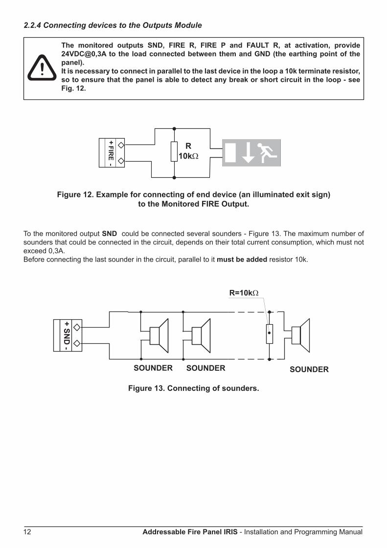
2.2.4 Connecting devices to the Outputs Module
The monitored outputs SND, FIRE R, FIRE P and FAULT R, at activation, provide 24VDC@0,3A to the load connected between them and GND (the earthing point of the panel).It is necessary to connect in parallel to the last device in the loop a 10k terminate resistor, so to ensure that the panel is able to detect any break or short circuit in the loop - see Fig. 12.
Figure 12. Example for connecting of end device (an illuminated exit sign) to the Monitored FIRE Output.
To the monitored output SND could be connected several sounders - Figure 13. The maximum number of sounders that could be connected in the circuit, depends on their total current consumption, which must not exceed 0,3A.Before connecting the last sounder in the circuit, parallel to it must be added resistor 10k.
Figure 13. Connecting of sounders.
!

Addressable Fire Panel IRIS - Installation and Programming Manual 13
2.2.5 Loop ExpanderThe IRIS fire panel operates with two loop controllers: Loop SS (System Sensor communication protocol) and Loop TTE (Teletek Electronics communication protocol). The Loop Controller (Figure 14) realizes the connection between the I/O Module and devices connected to the communication line. The Loop Expander has two basic functions: 1. Gathers data from the devices in the communication line and transfers it to the I/O Module; 2. Receives commands from the I/O Module and transfers them to the devices connected in the communication line. Every Loop SS provides up to 99 detectors and 99 modules.Every Loop TTE provides up to 250 devices (detectors and modules, regardless of the type)..The maximum current consumption of the devices in the communication line is Imax = 500mA. If the consump-tion exceeds this value an over-load protection would be turned on.In the configuration of analogue-addressable fire panel IRIS could be mounted up to 4 loop controllers.
1 - Interface connector for connecting the Loop expander to the I/O Module. 2 - Interface connector for connecting second loop expander.
Figure 14. General view of Loop Expander and an example for connecting devices to it.
Adding of loop expander in the configuration of the fire panel IRIS
FirstLoop Expander
I/O Module SecondLoop Expander
1 - Connect the interface connectors of the first and the second loop expanders. 2 - Fix the second loop expander with supplied bolts in the kit to the metal box of the fire panel.
ATTENTION: DO NOT ADD OR REMOvE LOOP ExPANDERS to the fire panel configuration WHEN THE MAIN AND BACkUP POWER SUPPLIES ARE ON!
Figure 15. Connecting of a second loop expander in the fire panel configuration.Note: The method of adding third and forth loop expander is analogical to that shown on Fig. 15.
Loop Controller
I/O Module First Loop Expander
SecondLoop Expander

14 Addressable Fire Panel IRIS - Installation and Programming Manual
2.2.6 Maximum permissible cable length • Loop Controller “Loop SS”The maximum length of the loop in the system could vary according to the cross-section and the ohmic resist-ance of the used cable. To make possible identifying devices with identical addresses (double addresses) in the system configuration, the cable resistance should not exceed definite calculated value. According to the ohmic cable resistance, calculate:
· Formula 1: LC1MAx = 21 / RC · Formula 2: LC2MAx = 80 / RC,Where:LC1MAx and LC2MAx - are maximum permissible length of the used cable, [km];RC - is total ohmic resistance of the two wires of the used able; its value shows the magnitude of the cable resistance at length 1km [Ω/km].If LC is the necessary length of the cable used in the loop, then: · At LC ≤ LC1MAx - the fire pane will be able to communicate with the devices in the circuit and also will be able to identify the presence of double address. · At LC1MAx < LC ≤ LC2MAx - the fire panel will be able to communicate with the devices in the circuit but will not be able to identify the presence of double addresses. · At LC > LC2MAx - the fire panel will not be able neither to communicate with the devices nor to identify the presence of double addresses.
Example:RC = 39 Ω/km, thenLC1MAx = 21 / RC = 21 / 39 ≈ 0,540kmLC2MAx = 80 / RC = 80 / 39 ≈ 2kmLC = 1kmIn this case it is possible to use the chosen cable in the system, but the fire panel will not be able to identify devices with double addresses. If this could not satisfying the requirements of the system it must be chosen cable with lower ohmic resistance RC.
• Loop Controller “Loop SS”The maximum length of the loop in the system could vary according to the cross-section and the ohmic resist-ance of the used cable. To ensure the correct operation of the system is necessary to make some calculations in advance:
1. To ensure the ability of the fire panel to receive the signals from the devices in the loop, calculate:
LC1max ≤ 123 / RC
2. To ensure the ability of the fire panel to recognize the double ad-dresses in the system, calculate:
LC2max ≤ 62 / RC
3. To ensure the ability of the devices in the loop to receive command sig-nals from the panel, calculate:
LC3max ≤ (12 / Imax - Ri) / RC
Where:LC1MAx , LC2MAx and LC3MAx - are maximum permissible length of the used cable, [km];RC - is total ohmic resistance of the two wires of the used able; its value shows the magnitude of the cable resistance at length 1km [Ω/km];RI - is the total resistance of the isolator modules in the loop;Imax - is the maximum current consumption in the loop - total amount of the current consumption of all devices in the loop.(Note: In case of using addressable base IRIS ligth B24A, the total amount for Imax includes: the maximal current con-sumption in alarm mode of 15 devices with base IRIS ligth B24A, and for the rest of the devices with base IRIS ligth B24A - the total consumption in stand-by mode.)
LC is the necessary length of the cable for the loop.

Addressable Fire Panel IRIS - Installation and Programming Manual 15
After calculating, the maximal length of the cable is determined according: · If LC ≤ LC2max and LC ≤ LC3max - the fire pane will be able to communicate with the devices in the loop and also will be able to identify the presence of double address. · If LC2max < LC ≤ LC1max and LC ≤ LC3max - the fire panel will be able to communicate with the devices in the loop but will not be able to identify the presence of double addresses.
ATTENTION: Always calculate the maximal cable length according the mentioned above formulas!IF LC > LC1max or LC > LC3max - the fire panel would not be able to communicate with the devices.
The connection diagram shown on Figure 16, gives the possibility to protect devices against opening and short-circuit. For example, short-circuit in section 2 will not influence the operation of sections 1 and 3. The isolator modules at the both ends of section 2 will isolate it, and section 1 and 3 will continue working properly, as section 1 will operate by supply from the channel “A” and section 3 - by supply from channel “B”. Since the fire panel will not be able to communicate with the devices from section 2, it will generate an alarm signal for lost devices and open circuit.
Isolatormodule
Section 1Protected premises
Isolatormodule
Isolatormodule
Section 3Protected premises
Section 3Protected premises
Figure 16. Example for connecting of detectors and call points to a loop expander.
The maximum number of devices between two isolator modules is 30!!
!

16 Addressable Fire Panel IRIS - Installation and Programming Manual
2.2.7 Main Power Source
Red LED forindication of V.220
BlackBlackYellow-green
Bla
ck
Bla
ck
Yello
w-g
reen
FuseF-Type
2А
MainPowerSource
LED-indication for the statusof Main Power Source.
Terminal block forexternal power supply.
1
2
3
4
5
61
2
3
4
Figure 17. General view of the power source and the terminal.
LED-indication of the power sourceLED Function Description
1 AC LOSS Main power supply loss 220V.2 Charger Fault Problem with the battery charging.3 BATT LOSS Battery loss.4 BATT Low Discharged battery.5 EARTH FAULT Resistance to GND ≤ 10kΩ.6 Rx / Tx Shows the communication with the panel.
Terminal Block for connecting to external power supply.Terminal Function Description
1 GND Input for connecting of external power supply EARTH.2 FAULT OUT Fault output, turns on when a problem with the main power supply
occurred. Connect it to the input (Fault In) of the external power supply.
3 FAULT IN Input for connecting the Fault output of the external power supply.4 +13.8V External power supply input.
Before the mains supply is switched on, check the correct connection of each loop, sounder or any other input or output.
BlackBlack
Red
LED indication for the statusof Main power source
Terminal block forexternal power supply
Main Power Source
Fuse 2AF type
Red LED for220V indication
BlackBlackYellow-green
Bla
ck
Bla
ck
Yello
w-g
reen

Addressable Fire Panel IRIS - Installation and Programming Manual 17
2.2.8 Connecting of the accumulator battery
Figure 18. Connecting the accumulator battery to the main power source.
· Connect the red cable to the positive pole of the battery, and the black cable - to the nega-tive battery pole. Both of the cables are connected to the battery by means of a flat terminal lug Ø5mm.
ATTENTION: The connection between the accumulator battery and the main power source has some spe-cial features. It is strongly recommended to use only battery with electrical characteristics and dimensions pointed from the manufacturer. Before connecting to the power source check the polarity of the battery. The battery cannot power up the panel before the mains supply has been switched on. Connect the battery after the mains supply is turned on. If the battery is new it will take a few hours before its complete charging!The charging of the accumulator battery is done at maximum current I=2A and charging voltage U < 13,8V.
Sealed lead acid typerechargeable battery
12V / 18Ah
MainPowerSource
RedBlack

18 Addressable Fire Panel IRIS - Installation and Programming Manual
2.3 Main Board SchematicsThe main board is situated on the back side of the front cover. On the main board is factory integrated a control module - uPC Module, for control of the panel functions and operations.
ATTENTION: Adjustment on the main board can be done from an authorized personnel only!
Figure 19. Main Board with integrated Control Module.Main board elements:• Restore Defaults - Resetting the panels with default parameters.• RS-232 - Serial interface• LAN - Connecting to Ethernet network.• USB - Mini USB connector.• ±12V - Additional power supply.• uPC Module !FAIL! - Yellow LED for uPC failure. • uPC Module - Control module integrated to the Main board• BUZ1/2 - Buzzers for sound signalization.• Contrast - Adjusting the display contrast.
2.4 Network connection diagramIt is possible to connect some individual IRIS fire panels in a network by means of a HUB and TCP/IP protocol - Figure 20. A supervisor PC, which could follow the current status of the individual fire panels, monitors the current panel state.
Figure 20.
!

Addressable Fire Panel IRIS - Installation and Programming Manual 19
3. PROGRAMMING3.0 Basic knowledge for operating with LCD touch-screen displayThe touch-screen display of the fire panel IRIS provides easy moving down the programming menus and entering of system parameters. The access to the programming menus is done with light pressing of the desired button. You can use also and a special pen for touch-screen display.According to the chosen menu and/or the access level there are active and inactive buttons on the screen. Choosing an active button leads to changing of the screen - you can move to a list of additional or submenus for programming, or you can enter new parameters in the system.
3.0.1 Terminology• Active Button - Pressing the button you can perform different operations: stop the sirens, reset the system parameters or move to other programming menus. • Inactive Buttons - The buttons do not respond when pressed. The parameters definition fields are also inactive. They just provide information of the parameter type.Note: The status of the buttons can alternatively change (active-inactive) according the programming menu and access level.• Panel Status Icons - The icons give information about the status of the fire panel and the programmed working mode. The icons are inactive if pressed. The different fire panel states are indicated with different colour of the icon. The icons and their state are described in item 5.2, page. 50.
• Used symbols
- Press the pointed button - Use a special pen for touch-screen display.
3.0.2 Initial Power-UpWhen turned on, the panel always conducts a procedure of loading the parameters, which usually takes about 30 sec. There is no access to the menus of the panel during that procedure.Upon the initial start up, the panel does not hold any configurations. Initialization may take several minutes. The initialization time needed depends on the number of periphery and loop devices. After the panel has been turned on, it performs a procedure for detecting newly installed periphery and loop devices - see also The APPENDIx E on page 58.
3.0.3 Default languageThe fire panel IRIS can support different languages of the programming menus. The factory default setting of the language is in English. You can change the language after the initial power-up as enter in sequence:
Access 1 → 3333 → OK → System → Programming → Panel → Languages → → Choose a language → Apply
After choosing the Apply button, you can return to the main screen by choosing the MENU button.
Date and timeinformation Panel Status Icons
ActiveButtons
InactiveButtons
20 Addressable Fire Panel IRIS - Installation and Programming Manual
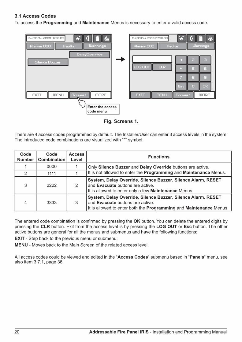
3.1 Access CodesTo access the Programming and Maintenance Menus is necessary to enter a valid access code.
Fig. Screens 1.
There are 4 access codes programmed by default. The Installer/User can enter 3 access levels in the system. The introduced code combinations are visualized with “*“ symbol.
Code Number
Code Combination
Access Level Functions
1 0000 1 Only Silence Buzzer and Delay Override buttons are active. It is not allowed to enter the Programming and Maintenance Menus.2 1111 1
3 2222 2System, Delay Override, Silence Buzzer, Silence Alarm, RESET and Evacuate buttons are active. It is allowed to enter only a few Maintenance Menus.
4 3333 3System, Delay Override, Silence Buzzer, Silence Alarm, RESET and Evacuate buttons are active. It is allowed to enter both the Programming and Maintenance Menus
The entered code combination is confirmed by pressing the OK button. You can delete the entered digits by pressing the CLR button. Exit from the access level is by pressing the LOG OUT or Esc button. The other active buttons are general for all the menus and submenus and have the following functions:ExIT - Step back to the previous menu or submenu;MENU - Moves back to the Main Screen of the related access level.
All access codes could be viewed and edited in the “Access Codes“ submenu based in “Panels“ menu, see also item 3.7.1, page 36.
Enter the accesscode menu

Addressable Fire Panel IRIS - Installation and Programming Manual 21
There are different restrictions on the panel functions in the relative access levels, which are shown in the following table:
Function Description Level 1
Level 2
Level 3
Con
trol
Pan
el
Silence Buzzer Deactivating Internal Buzzer √ √ √Silence Sounder Deactivating the Sounders - √ √Delay Override Resetting of all active outputs delay, excepting Fire Protection √ √ √Reset Resetting of all active statuses - √ √Evacuate Activating Evacuation alarm signal - √ √Alarms Viewing the Alarms Messages in the system √ √ √Faults Viewing the Faults Messages in the system √ √ √Warnings Viewing the Warnings Messages in the system √ √ √Menu Main Screen √ √ √Access Level Entering an access code √ √ √
Syst
em
Prog
ram
min
g
Device Device Programming - - √Zones Zone Programming - - √Inputs/Outputs Inputs/Outputs Programming - - √Panel Panel Programming - - √Restore Default Restore the default parameters - - √Save Save the configuration - - √
Mai
nten
ance
Time/Date Entering current time and date - - √Day Day Schedule introducing - - √Output Delay Output Delay Introducing - - √View LOG View the LOG-file - - √Test Testing - √ √Disable Disable Introducing - √ √Software Revision View the software revision - - √Calibration Calibration of the Display - - √

22 Addressable Fire Panel IRIS - Installation and Programming Manual
!
3.2 Programming MenuThe programming of the panel is done only from the access level 3 - Fig. Screens 2. Choose the System Button. From the next screen the Installer/User can choose the type of the operation, which he want to do:
1. To program system parameters - Programming Menu.2. To study the panel operation, as to enter different parameters for the maintenance of the system - Maintenance Menu.
Fig. Screens 2.To enter in the Programming Menu the Installer should choose Programming Button. The main screen of the Programming Menu is displayed on Fig. Screen 3.
Fig. Screen 3.
On the left side of the screen are located buttons for entering submenus for parameter programming of De-vices, Zones, Inputs, Outputs and Access Codes. To enter a desired submenu just choose its button.Choosing the button “Restore Defaults” on the right side of the screen can restore all the factory settings. Button “Save” is for quick saving of the entered information.
With the button “Exit” in the bottom left corner the user/installer can easy move one step back on the previous screen.
Devices
Zones
Inputs
Outputs
Panel
Restoring of the factory settings
Buttons for quick saving of the whole panel configuration

Addressable Fire Panel IRIS - Installation and Programming Manual 23
3.3 DevicesThe addressable fire panel IRIS light supports periphery and loop devices. All “functional modules” connected to the control panel configuration are defined as Periphery Devices, and have special programming and setting. The Main board is not a periphery device. All addressable devices connected to loop expaneder are defined as Loop Devices. With choosing the “Device” button the user/installer enters a menu for choosing the type of the device - Fig. Screen 4.
Fig. Screen 4. 3.3.1 Periphery DevicesChoosing “Periphery Device” button leads to submenu for entering the parameters of the available periphery devices in the system configuration - Fig. Screen 5. The list of supported periphery devices is:· PSU Power source - see Figure 5· OUT (Input/Output Module) - 4 input/ 4 monitored outputs/ 4 relays· OUT (Input/Output Module + 4 Relay Expander Module)· LOOP (Loop controller type Loop SS and Loop TTE) If there is no device detected on the current address, the address is EMPTY.
3.3.1.1 Physical Address of Periphery DeviceThe panel is able to operate with up to 10 periphery devices, addressed 1 to 10. The devices can be self-addressed, whereby the first along the loop acquires the lowest address. The power supply source always acquires address 1. You can choose the next/previous device address by pressing the navigation buttons.
3.3.1.2 Current Status of the DeviceThe running status of the device can be:• NEW - the device is new to the system. It must be saved. The main board is recognized a physical presence of a device, which is not included in the system configuration. The new device has to be added to the system configuration so the panel to be able to communicate with it - to receive an alarm or trouble messages, to activate and to receive signals, etc. The new device can be add to the system configuration with pressing the SAVE button. Note: The device is defined as NEW in two cases:1. A device has been physically added to the hardware configuration of the panel. Use the “SAVE” button. (For example when a loop expander is added to the system configuration).2. A device has been removed from the system configuration (with “REMOVE” button), but it is still present in the hardware configuration - it is not physically removed. The panel will recognize the presence of the device in the loop, but it is not added to the system configuration, so the device is NEW for the panel. •NORMAL - the device is properly operating. • FAULT - the device does not respond.• TYPE ERROR - a device, different from that saved, has been detected. Use the “CHANGE“ button to change the device type.
Button for entering periphery devices pro-
gramming submenu
Button for entering loop devices program-
ming submenu

24 Addressable Fire Panel IRIS - Installation and Programming Manual
3.3.1.3 Adding a new periphery device to the panelUpon detecting a new periphery device (which is missing in the configuration), the following message will be displayed: “NEW PERIPHERY DEVICES FOUND”, and the number of the detected devices will be indicated. Choose the SAVE button to add the new periphery devices to the panel configuration. If a device is not re-sponding you can remove it as choosing the REMOVE button.
Fig. Screen 5 PSU Parameters (Power source)
4
Fig. Screen 6 – OUT (I/O module + 4 Relay Expander Module)

Addressable Fire Panel IRIS - Installation and Programming Manual 25
Fig. Screen 7 - LOOP (Loop controller) - Example for adding/ removing of new periphery device in LOOP TTE
Note: After choosing the SAvE button it disappears from the screen and the status of the device from NEW changes to NORMAL.
3.3.2 Loop DevicesTo enter the submenu for programming of the loop devices parameters from “Device” menu choose button “Loop Devices” - Fig. Screen 4.
Attention: The device searches for new loop devices only when the respective loop con-troller has been added to the configuration.
When a new loop device is found (missing in the configuration) the message “NEW LOOP DEVICES FOUND” will be generated, as well as the number of detected devices. The message is generated by loops. Adding a new device to the configuration is accomplished with the APPLY command from the specific device menu or with the help of the general SAVE command from the Programming menu. Any device, which has not been added to the configuration, cannot generate messages. In case of removal of a loop device, the panel gener-ates a ”LOOP DEVICE FAULT” message. When a newly detected device is removed, the panel reduces the number of the new devices and if their number is 0 it shall extinguish the “NEW LOOP DEVICES FOUND” message. Removing the device from the configuration is accomplished with the REMOVE command in the menu for the specific device.Where in abundance, it is possible for device addresses to double along the loops (see also item 2.2.7 Maxi-mum permissible cable length). In such cases the message “DOUBLE ADDRESS” will be displayed along with the problem address. Should a different device type appear at the address of a saved device, the panel will generate “LOOP DEVICE TYPE ERROR”. In LOOP SS the new device can be saved by selecting the correct type from the menu of types and the APPLY command in the menu for the specific device. For LOOP TTE first you need to remove wrong and then to save the new type of the device.
• Loop Controller LOOP SSThe loop controller LOOP SS cannot distinguish the types of devices in one and the same area. This requires each type of device to be further defined by the installer. For ease of introduction, the panel suggests possible devices for selection. Information for correspondence of the device types is given in APPLICATION: Maintained System Sensor Devices and Appendix B - Tables for correspondence of the System Sensor device types. The “SAVE” button can be used for fast configuration of the device. Following this command, the panel sets up all detected loop and periphery devices by default. New devices only are configured under this command. The “RESTORE DEFAULTS” command deletes all system parameters.
!
* It could be: Loop SS - System Sensor; Loop TTE - Teletek Electronics
*

26 Addressable Fire Panel IRIS - Installation and Programming Manual
Fig. Screen 8.
On Fig. Screen 8 is given the general view of the submenu for new loop System Sensor devices configuration connected to LOOP SS.
Description of the button functions (Fig. Screen 8):
• Confirm Change Button - Saves changes in the permanent memory.
• Button to enable/disable a device - Button for Enabling / Disabling devices.
• Module or sensor selection button - This button is used to switch over between module and detector addresses.
• Address Navigation Button - This button helps to scroll (in sequence or directly) the devices of one and the same loop.
• Loop Number Navigation Button - These keys alternate the loop (in sequence or directly) of the screened devices.
• Zone Selection Button - These keys alternate the zone (in sequence or directly) to which the device belongs.
• Current Device Status - The current device status varies according to the device type. NEW - new device found in the system. You can save it by pressing the “Apply” button. NORMAL - the device is working properly. FAULT - the device is not responding. You can delete it by pressing the “REMOVE” button. TYPE ERROR - the device has been saved with a different type. NONE - there is no device on the current address.
• Button for Removing a device - Pressing the button deletes the device from the system configuration.
• Change Device Type Button - Press this button for the panel to provide a compatibility device list of which to choose the most suitable one. The “SELECT NEW DEVICE TYPE” message will be portrayed Fig. Screen 9.
• Active Field for Text Introduction - Choosing this field accesses the text introduction mode. The text must not exceed 40 digits together with the spaces - Fig. Screen 10. Entered information is confirmed with button .
• Additional Settings Button - The additional adjustments vary according to the type of device. Setting the day and night time mode, as and setting the levels of the alarm signal (FIRE) - Fig. Screen 11, is performed by pressing of the respec-tive button and entering of the desired value by means of an additional keypad displayed on the screen.

Addressable Fire Panel IRIS - Installation and Programming Manual 27
Figure Screen 9. Figure Screen 10.
The Installer/User can choose how to write the device names - with Cyrillic or Latin letters. The buttons of the keypad have the following meaning:
Button FunctionCyr Switches to Cyrillic letters.SPE Switches to Spanish letters and symbols.Lat Switches to Latin letters.Sym Switches to specific symbols.A/a Switches between capital and small letters.Num Switches to numbers.
Space.Deletes numbers or letters.
Confirmation of the entered numbers or letters.
Fig. Screen 11. Additional settings for System Sensor devices.
]

28 Addressable Fire Panel IRIS - Installation and Programming Manual
• Loop Controller LOOP TTEThe loop controller LOOP TTE automatically recognizes the types of devices in the loop. In addition the installer defines the temperature class and the sensitivity level of the SensoIRIS devices according their type - see also the Appendix C - SensoIRIS device types. The “SAVE” button can be used for fast configuration of the device. Following this command, the panel sets up all detected loop and periphery devices by default. New devices only are configured under this command. The “RESTORE DEFAULTS” command deletes all system parameters.On Fig. Screen 12 is given the general view of the submenu for new loop Teletek Electronics devices for LOOP TTE (SensoIRIS MCP150 in the example).
Fig. Screen 12
Description of the button functions (Fig. Screen 12):
• Confirm Change Button - Saves changes in the permanent memory.
• Button to enable/disable a device - Button for Enabling / Disabling devices.
• Address Navigation Button - This button helps to scroll (in sequence or directly) the devices of one and the same loop.
• Loop Number Navigation Button - These keys alternate the loop (in sequence or directly) of the screened devices.
• Zone Selection Button - These keys alternate the zone (in sequence or directly) to which the device belongs.
• Current Device Status - The current device status varies according to the device type. NEW - new device found in the system. You can save it by pressing the “Apply” button. NORMAL - the device is working properly. FAULT - the device is not responding. You can delete it by pressing the “REMOVE” button. TYPE ERROR - the device has been saved with a different type. NONE - there is no device on the current address.
• Button for Removing a device - Pressing the button deletes the device from the system configuration.
• Change Device Type Button - Press this button for the panel to provide a compatibility device list of which to choose the most suitable one. The “SELECT NEW DEVICE TYPE” message will be portrayed Fig. Screen 9.
• Active Field for Text Introduction - Choosing this field accesses the text introduction mode. The text must not exceed 40 digits together with the spaces - Fig. Screen 10. Entered information is confirmed with button .
• Additional Settings Button - The additional adjustments vary according to the type of device - see the Fig. Screen13a - 13d.

Addressable Fire Panel IRIS - Installation and Programming Manual 29
Fig. Screen 13a - SensoIRIS S130 fire detector.
On Fig. Screen 13a is shown the SensoIRIS S130 (addressable optical smoke detector) settings screen. Choose the “MORE” button to enter a screen with additional settings:• Return value - A digit number sent form the devices to the control panel.• Led Blink - Button for changing the LED mode: ON Setting - The LED blinks at every query from the station; OFF Setting - The LED does not show the dialogue cycle.• Day Alarm Level* - Setting the day alarm level.• Night Alarm Level* - Setting the night alarm level.* There are 4 levels for setting of alarm level sensitivity: High, Normal, Middle and Low. To change the level of sensitivity simple press the active button next to the field and choose a new level from the list.To save the new setting press the “SAVE” button on the main screen.
Fig. Screen 13b - SensoIRIS T110 fire detector.
On Fig. Screen 13b is shown the SensoIRIS T110 (addressable temperature detector) settings screen. Choose the “MORE” button to enter a screen with additional settings:• Return value - A digit number sent form the devices to the control panel.• Led Blink - Button for changing the LED mode: ON Setting - The LED blinks at every query from the station; OFF Setting - The LED does not show the dialogue cycle.• Day Alarm Level, temp* - Setting the day class temperature for operation.• Night Alarm Level, temp.* - Setting the night class temperature for operation.* There are 3 temperature classes for operation: A1R (58º,RoR), A2S (60º), BS (75º). To change the class simple press the active button next to the field and choose a new level from the list.To save the new setting press the “SAVE” button on the main screen.

30 Addressable Fire Panel IRIS - Installation and Programming Manual
Fig. Screen 13c - SensoIRIS M140 fire detector.
On Fig. Screen 13c is shown the SensoIRIS M140 (addressable optical smoke and temperature RoR detector) settings screen. Choose the “MORE” button to enter a screen with additional settings:• Return value - A digit number sent form the devices to the control panel.• Led Blink - Button for changing the LED mode: ON Setting - The LED blinks at every query from the station; OFF Setting - The LED does not show the dialogue cycle.• Day Alarm Level. Set here the sensitivity level of the optical parts of the detector and enable/ disable the heat part. These settings are valid for the daytime:
- Sensitivity level. There are 4 levels for setting of alarm level sensitivity for the optical part: High, Normal, Middle and Low. To change the level of sensitivity simple press the active button next to the field and choose a new level from the list.- Heat part. In addition for this device only the installer can enable or disable the heat part of the detector. The state of the heat part can be changed with pressing the button.
• Night Alarm Level. Set here the sensitivity level of the optical parts of the detector and enable/ disable the heat part. These settings are valid for the nighttime. Operation of setting is the same with those for the day alarm level.
Attention: It is not allowed disabling the temperature and the optical parts at the same time!To save the new setting press the “SAVE” button on the main screen.
Fig. Screen 13d - B24A fire base for conventional SensoMAG detectors.
• Day Verify Time (seconds) - Setting of daytime confirmation of alarm.• Night Verify Time (seconds) - Setting of nighttime confirmation of alarm.
Important Note: The alarm must remain active during the programmable period of time in order to generate an alarm event from the panel. If the detector restores its normal state prior to time-out, the panel shall not generate alarm.

Addressable Fire Panel IRIS - Installation and Programming Manual 31
3.4 ZonesChoose in sequence from the Main menu screen System - Programming - Zones.The IRIS light addressable fire panel avails of 96 zones. The FIRE and PREALARM conditions are indicated by the help of the LED of the corresponding zone. In the PREALARM condition - the respective zone LED blinks and a warning message is displayed on the screen. If there is a second activation of devices in the same zone an alarm message FIRE is generated for the respective zone. To enter the submenu for zone configuration, chose “Zones” button from Programming menu - Fig. Screen 3. The general view of the zone configuration menu is shown on Fig. Screen 14.
Fig. Screen 14.
3.4.1 Button for Selecting the Zone NumberThe zone number can be selected in sequence or directly, which can than be monitored.3.4.2 Active Field for Introducing Zone NameChoose the button to enter the screen (Fig Screen 9), for introducing the zone name, which shall not exceed 40 digits together with the spaces. Verify the information with the button.3.4.3 Button for Zone Mode ChangeEach zone has two working modes: NORMAL and 2DEVICES. · In NORMAL mode any detector activation within the system generates an alarm event to the respective zone. · In 2DEVICES mode any detector activation within the system generates a PREALARM event to the respec-tive zone, but also awaits the activation of another detector from the same zone to generate a FIRE signal. The RESET command shall disable the FIRE and PREALARM events.3.4.4 Sounder Delay (T2)*The delay can be within an interval of 0-540 sec.In case of activation of more than one zone, the delays to the outputs are caused by the zone with shorter delays.
3.4.5 Fire output Delay (T2)*The delay can be within an interval of 0-540 sec.In case of activation of more than one zone, the delays to the outputs are caused by the zone with shorter delays.3.4.6 Fire protection Output Delay (T2)*The delay can be within an interval of 0-540 sec.In case of activation of more than one zone, the delays to the outputs are caused by the zone with shorter delays.3.4.7 Enable/Disable Zone Button - Button for Enabling / Disabling zones.
All changed parameters are confirmed and saved by pressing the APPLY button in the upper left cor-ner of the screen.
* Note: Т2 presents times for individual output delay setting. See APPENDIX E - Two steps of alarming algorithm.

32 Addressable Fire Panel IRIS - Installation and Programming Manual
3.5 InputsTo enter the submenu for inputs configuration choose “Inputs” button from Programming menu – Fig. Screen 3. The general view of the menu for inputs configuration is shown on Fig. Screen 15.
Fig. Screen 15 – Menu for introducing input parameters.
3.5.1 Input delay. The delay can be within the interval 0–600 sec.3.5.2 Input Active Status (Polarity) INvERTED - the output is set at ON, when the result of the logical function is FALSE. NORMAL - the output is set at ON, when the result of the logical function is TRUE.3.5.3 Behaviour LATCHED - deleted only after RESET. UNLATCHED - monitors the status.3.5.4 Type Selection MenuBy pressing the button for input type a new screen is displayed from which can be chosen the following types:
NONE Periphery Loop Zone
Time Date Action General
Network
After choosing the desired type it is introduced in the Type field of the screen - Fig. Screen 12.
3.5.5 Submenus for setting of input type parameters Depending on the type of input after choosing the button MORE could be programmed the parameters of every input type. The information is displayed on a separate screen. There can be programmed the following parameters:• PERIPHERY - Choose the MORE button. Set the parameters in the screen “INPUT Parameters - periphery devices”: - Address of periphery device. Enter an address number from 1 to 10. - Input of periphery device. The button have two states - ON and OFF, according the type of the device. Enter a periphery device input number.• LOOP - Choose the MORE button. Set the parameters in the screen “INPUT Parameters - loop devices”: - Address of loop device. Enter an address number from 1 to 250. - Loop number. Enter the loop number. - Type of the device. - Channel. Enter a serial number of an input accessible in the device.
Note: It is possible to enter addresses only of loop devices, which are INPUT type: detectors, call points, input-outputs modules! If the device if not an INPUT type a message is shown: “This device can not be used as Input!”

Addressable Fire Panel IRIS - Installation and Programming Manual 33
• ZONE - Number of zone and event for activation.Choosing the Zone type of the input will add a new field Function - Fig. Screen 16. After choosing this field the possible zone events will be displayed on the screen.
Fig. Screen 16 - Menu for zone events introducing.
Choose the MORE button. Set the the zone number, from 1 to 96, in the screen “INPUT Parameters - zone”.
• TIME - Device input activation time. Choose the MORE button. Set the hour, minutes and day of the week when the input has to be activated, in the screen “INPUT Parameters - time”. Every day of the week could be enabled or disabled in a separate screen.
• DATE - Device input activation date. Choose the MORE button. Set the year, month and the day when the input has to be activated, in the screen “INPUT Parameters - date”. Enter.
• ACTION - Device input activation action.Choosing the Action type of the input will add a new field Function - Fig. Screen 16. The possible actions are as fol-lows: - SILENCE BUZZER - SILENCE SOUNDER - RESET - SOUNDER ON - FIRE BRIGADE ON - FAULT ROUTING ON - FIRE PROTECTION ON
• GENERAL - General status which will activate the input of the device.Choosing the General type of the input will add a new field Function - Fig. Screen 16. The possible statuses can be: - COMMON FIRE - COMMON PREALARM - COMMON FAULT - SYSTEM FAULT - DISABLED - TEST
• NETWORK - Panel / repeater number and output number, to which the input shall be attached. Choose the MORE button. Set the parameters in the screen “INPUT Parameters - network”: - INPUT Number. Enter a number from 1 to 128. - PANEL/REPITER Number. Enter a number from 1 to 32.
All changed parameters are confirmed and saved by pressing the APPLY button in the upper left corner of the screen.
34 Addressable Fire Panel IRIS - Installation and Programming Manual
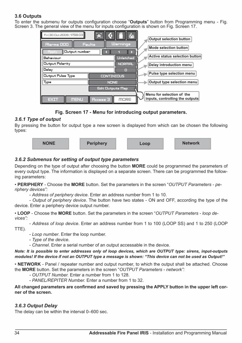
3.6 OutputsTo enter the submenu for outputs configuration choose “Outputs” button from Programming menu - Fig. Screen 3. The general view of the menu for inputs configuration is shown on Fig. Screen 17.
Fig. Screen 17 - Menu for introducing output parameters.3.6.1 Type of outputBy pressing the button for output type a new screen is displayed from which can be chosen the following types:
3.6.2 Submenus for setting of output type parameters Depending on the type of output after choosing the button MORE could be programmed the parameters of every output type. The information is displayed on a separate screen. There can be programmed the follow-ing parameters:
• PERIPHERY - Choose the MORE button. Set the parameters in the screen “OUTPUT Parameters - pe-riphery devices”: - Address of periphery device. Enter an address number from 1 to 10. - Output of periphery device. The button have two states - ON and OFF, according the type of the device. Enter a periphery device output number.
• LOOP - Choose the MORE button. Set the parameters in the screen “OUTPUT Parameters - loop de-vices”: - Address of loop device. Enter an address number from 1 to 100 (LOOP SS) and 1 to 250 (LOOP TTE). - Loop number. Enter the loop number. - Type of the device. - Channel. Enter a serial number of an output accessable in the device.Note: It is possible to enter addresses only of loop devices, which are OUTPUT type: sirens, input-outputs modules! If the device if not an OUTPUT type a message is shown: “This device can not be used as Output!”
• NETWORK - Panel / repeater number and output number, to which the output shall be attached. Choose the MORE button. Set the parameters in the screen “OUTPUT Parameters - network”: - OUTPUT Number. Enter a number from 1 to 128. - PANEL/REPITER Number. Enter a number from 1 to 32.All changed parameters are confirmed and saved by pressing the APPLY button in the upper left cor-ner of the screen.
3.6.3 Output DelayThe delay can be within the interval 0–600 sec.

Addressable Fire Panel IRIS - Installation and Programming Manual 35
3.6.4 Output Active Status (Polarity)• INvERTED - the output is set at ON, when the result of the logical function is FALSE.• NORMAL - the output is set at ON, when the result of the logical function is TRUE.
3.6.5 Pulse Type• CONTINUOUS - the output signal is continuous• PULSED - the output signal is a pulse signal (3 sec. ON / 3 sec. OFF)• ONE PULSE - the output signal is a single pulse signal (5 sec)
ONE PULSE must be used in the case of ACTION type activating input or else the activat-ing input must be LATCHED or the output LATCHED.
3.6.6 Behaviour (Mode)• LATCHED – deleted only after RESET.• UNLATCHED – monitors the status.
3.6.7 Menu for selection of the inputs, controlling the outputs
Fig. Screen 18
All changed parameters are confirmed and saved by pressing the APPLY button in the upper left cor-ner of the screen.

36 Addressable Fire Panel IRIS - Installation and Programming Manual
3.7 PanelChoose in sequence from the Main menu screen System - Programming - Panel.From the Panel Menu you can switch over seven additional submenus and to change the access codes and level, and to set parameters of the available network, sounders and call points modes.
Fig. Screen 19 - The Panel Menu.
3.7.1 Changing the Code and Access LevelThe system supports 4 separate access codes, as to which of them can be given different access level. See item 3.1 where are described the default setting of the codes and access levels. Every code has 4 digits.
Fig. Screen 20 - Codes and Access Level Introducing.
The new code introducing is done in a separate screen (see also Fig. Screens 1). After the code is initially en-tered, the system shall request the code to be entered again for verification. If the codes differ the system will ignore whatever was entered and the old code will remain active. If both codes are identical, the new code will be displayed in the “ACCESS CODES” output field and an “Apply” button will appear. Select “Apply” to save the entered code. If a code has already been entered the system will ignore it and will retain the old one.Changing the level of access is done by choosing the “Access Code Level” button next to the field for calling out the access level. When activated a menu appears in which the user selects a new level of access (1-3) by pressing the respective button or “ExIT” to leave. If the newly assigned access level is different from the current one, the “Apply” button will be activated. Pressing that will save the new access level.
There must be at least one code in the system with an access code 3! The pro-gram disallows editing a level of access (3) if it is the only one!!

Addressable Fire Panel IRIS - Installation and Programming Manual 37
3.7.2 NetworkAfter choosing the Network button a new screen will be displayed. The Installer / User can set there the pa-rameters of two submenus: Network Settings and Panels.3.7.2.1 Network Settings MenuIn this menu can be set parameters for the separate fields - see Fig. Screen 21.• Name - Introduce the name of the panel - up to 40 digits.• Port - TCP/IP port for communication with the panel is introduced. The panel automatically takes ports Port+1, Ports+2. They have to be free for using from the panels. All the panels in the network have to be with the one and the same port number. If a port change is needed and made the panel have to be reset by power supply.• Panel Number - An unique panel number (1-32) in the network is introduced. By this number the panels can “recognize“ each other.• Network Status - The network can be Enabled and Disabled.All changed parameters are confirmed and saved by pressing the APPLY button in the upper left cor-ner of the screen.
Fig. Screen 21 - General View of Network Settings Menu.
From Network Settings menu can be programmed additionally panel IP, Netmask and IP-number of the Router, as and to be seen the panel MAC-address after choosing the MORE button - see Fig. Screen 21A.
Fig. Screen 21A

38 Addressable Fire Panel IRIS - Installation and Programming Manual
3.7.2.2 Panels MenuAfter Enabling the Network, every panel starts looking for other panels in the network. If a new panel is found in the system it is added to the panels list. The list can be viewed by using the pointers and the IP-numbers of the found panels are displayed. If the panel will be included in the Network it must be saved by ADD com-mand on the screen. Then the status of the panel from New Panel will turn to Present. The panels can “look at“ each other and if any of them is lost its status will change to Fault. From this menu can be chosen also what information would be received from the respective panel: messages and/or commands.
Fig. Screen 22 - General view of the Panels Menu.
If the messages receiving is Enabled, the Installer / User should describe also the input action as choose the MORE button - Fig. Screen 22A. Every message can be enabled or disabled.
Fig. Screen 22A.The messages have the following meanings:• Repeat Sounder - Follows the Sounder output status of the remote panel including the delays.• Repeat Fire Brigade - Follows the Fire Brigade output status of the remote panel including the delays.• Repeat Fault Routing - Follows the Fault Routing output status of the remote panel including the delays.• Repeat Fire Protection - Follows the Fire Protection output status of the remote panel including the de-lays.
All changed parameters are confirmed and saved by pressing the APPLY button in the upper left corner of the screen.!

Addressable Fire Panel IRIS - Installation and Programming Manual 39
If a panel from the Network is lost the other panels will generate a message “Panel Fault“ - Fig. Screen 23. If there is doubling of IP and network numbers, the panels with doubled numbers generate a Fault message. You can access to the Fault messages by pressing the Button Fault from the Panels menu.
Fig. Screen 23.
3.7.3 Disabling the Earth Fault Indication By pressing the button Earth Fault from the Panel menu (see Fig. Screen 19), a screen for enabling/ disa-bling the earth fault indication is displayed. Press the “Apply” button to introduce changes.
3.7.4 Sounders ModeChoose button Sounders Mode from Panel menu to enter in this submenu - see Fig. Screen 19. The Installer has a possibility to choose the Sounders mode - Common or Zonal. For this purpose on a separate screen are displayed buttons, as:• Common - All sounders will be activated with no sense of zone to which they are connected.• Zonal - Only the sounder of the zones with alarm condition will be activated.
Fig. Screen 24 - Choosing a Sounders Mode.
All changed parameters are confirmed and saved by pressing the APPLY button in the upper left cor-ner of the screen.

40 Addressable Fire Panel IRIS - Installation and Programming Manual
3.7.5 Call point ModeChoose button Call points Mode from Panel menu to enter in this submenu - see Fig. Screen 19. The In-staller has a possibility to choose the alarm mode if a call point is been activated - Common or Zonal. For this purpose on a separate screen are displayed buttons, as:• Common - A general alarm will be activated with no sense of to which zone the call point is been con-nected.• Zonal - Only an alarm in the zone where the call point is been connected.
Fig. Screen 25 - Choosing a Call points Mode.
All changed parameters are confirmed and saved by pressing the APPLY button in the upper left cor-ner of the screen.
3.7.6 Language selectionHere the Installer can choose between the available languages in the system.
3.7.7 Delay (T1)Here the Installer can set a common time delay for activation for all outputs (from 0 to 60 seconds). By default a 30 seconds time delay is set in the system.
See also APPENDIX E - “Two steps of alarming” working algorithm.
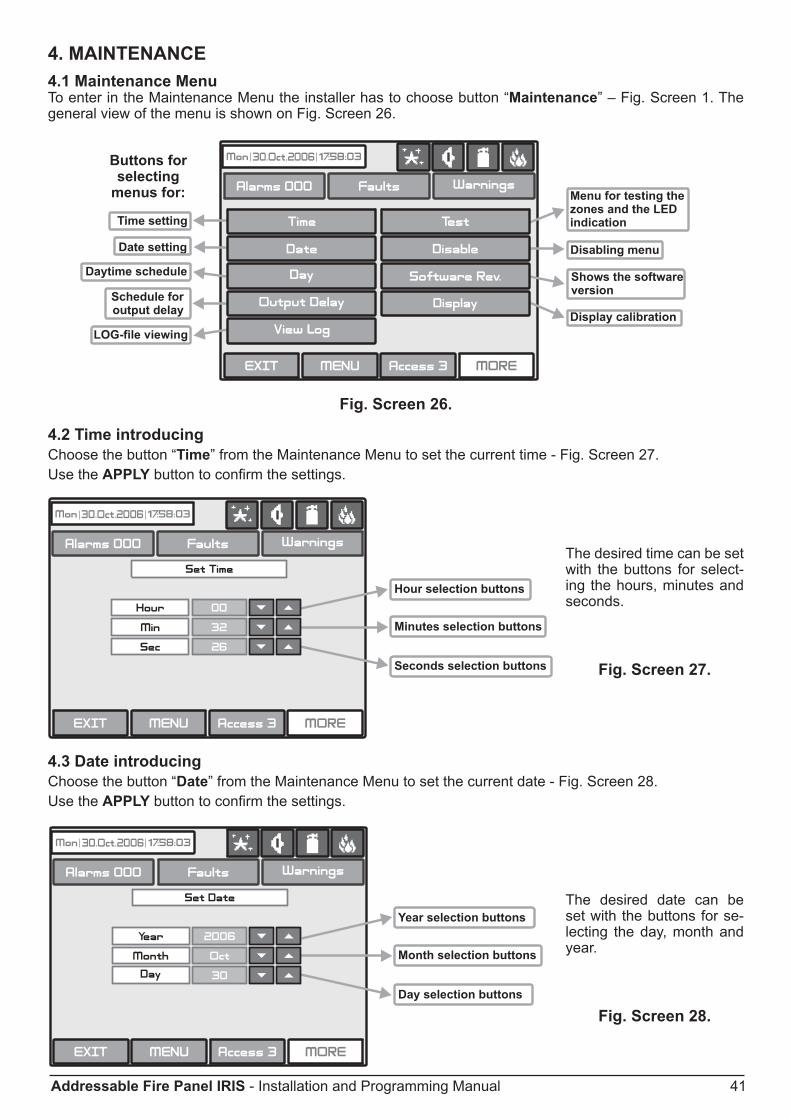
Addressable Fire Panel IRIS - Installation and Programming Manual 41
4. MAINTENANCE4.1 Maintenance MenuTo enter in the Maintenance Menu the installer has to choose button “Maintenance” – Fig. Screen 1. The general view of the menu is shown on Fig. Screen 26.
Fig. Screen 26.
4.2 Time introducingChoose the button “Time” from the Maintenance Menu to set the current time - Fig. Screen 27. Use the APPLY button to confirm the settings.
The desired time can be set with the buttons for select-ing the hours, minutes and seconds.
Fig. Screen 27.
4.3 Date introducingChoose the button “Date” from the Maintenance Menu to set the current date - Fig. Screen 28.Use the APPLY button to confirm the settings.
The desired date can be set with the buttons for se-lecting the day, month and year.
Fig. Screen 28.

42 Addressable Fire Panel IRIS - Installation and Programming Manual
4.4 Daytime ModeChoose the button “Day” from the Maintenance Menu to set the daytime schedule for detectors operation. The Daytime operating mode can be enabled (ON), disabled (OFF) or to follow a time schedule (Schedule) Fig. Screens 29.
Fig. Screens 29
In this mode the detectors use the alarm level which has been programmed as day mode. This is usually a level of lower sensitivity. It lowers the risk of false alarms caused by dust, cigarette smoke, etc. Night time mode is opposite to the daytime mode (higher level of sensitivity).
Fig. Screen 30
In Schedule mode the initial hour and minutes (the time when the daytime mode is activated) and the end hour and minutes (the time when the night time mode is activated) are introduced. The times are set for every day of the week. By default the station is in night time mode.
The Day time operating mode is indicated with icon in the system status field.
All changed parameters are confirmed and saved by pressing the APPLY button in the upper left cor-ner of the screen.

Addressable Fire Panel IRIS - Installation and Programming Manual 43
4.5 Output Delay IntroductionChoose the button “Output Delay” from the Maintenance Menu to set the output delay – Fig. Screen 31.
Fig. Screen 314.5.1 Sounder DelayChoose “Sounder Delay” button from “Output Delay” Menu - Fig. Screen 31 to enter the submenu for sound-er delay introduction - Fig. Screen 32.A delay can be added before the sounders are turned on. This provides the possibility of checking the authen-ticity of the alarm before the sounders are turned on (an official visits the site and inspects for fire).
Fig. Screen 32 - Sounders Delay Introducing.In Schedule mode the initial hour and minutes (the time when the delay is activated) and the end hour and minutes (the time when the delay is deactivated) are introduced. The times are set for every day of the week. During turned on “Delay” the LED is active.

44 Addressable Fire Panel IRIS - Installation and Programming Manual
4.5.2 Fire output DelayChoose “Fire Br. Delay” button from “Output Delay” Menu - Fig. Screen 31 to enter the submenu for fire output delay introduction (the screen is the same as those for sounder delay introduction).A delay can be added before the sounders are turned on (fire output). This provides the possibility of check-ing the authenticity of the alarm before the sounders are turned on (an official visits the site and inspects for fire).The delay can be: ON, OFF or Schedule. In Schedule mode the initial hour and minutes (the time when the delay is activated) and the end hour and minutes (the time when the delay is deactivated) are introduced. The times are set for every day of the week. During turned on “Delay” the LED is active.
4.5.3 Fire Protection DelayChoose “Fire Pr. Delay” button from “Output Delay” Menu - Fig. Screen 31 to enter the submenu for fire pro-tection delay introduction (the screen is the same as those for sounder delay introduction).A delay can be added before the fire protection system is turned on. This provides the possibility of check-ing the authenticity of the alarm before the sounders are turned on (an official visits the site and inspects for fire).The delay can be: ON, OFF or Schedule. In Schedule mode the initial hour and minutes (the time when the delay is activated) and the end hour and minutes (the time when the delay is deactivated) are introduced. The times are set for every day of the week. During turned on “Delay” the LED is active.
All changed parameters are confirmed and saved by pressing the APPLY button in the upper left cor-ner of the screen.
4.6 LOG-file viewChoose “View Log” from the Maintenance Menu to enter in a screen for viewing the happened events in the system. The addressable fire panel IRIS light can show maximum 10 000 events, which could be viewed by date or number - Fig. Screen 33.
Fig. Screen 33.

Addressable Fire Panel IRIS - Installation and Programming Manual 45
4.7 TestingThe addressable fire panel IRIS light has an option for testing of zone functioning and the LED-indication of the panel. To make a test, choose the “Test” button from Programming Menu - Fig. Screen 26. On the displayed screen the user/ installer could choose which test to perform - zone or LED-indication testing - Fig. Screen 34.
Fig. Screen 34.After choosing the desired test by pressing the respective button, the user/installer could examine the proper functioning of each zone and the LED-indication of the front panel. The entered information has to be con-firmed by pressing “Apply” button.
4.8 Disable introducingThe user/installer can enable or disable the loop devices, zones and the outputs of the fire panel. To introduce enabling or disabling a function you can directly choose the respective button and make corrections, or first by pressing “View” button to look at the current status of the system and after that, if it is necessary, to enter new data – Fig. Screen 35.
Fig. Screen 35.
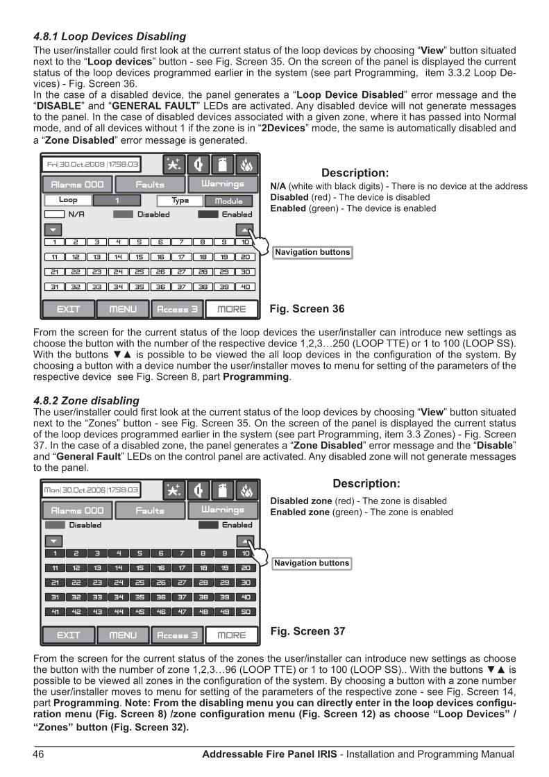
46 Addressable Fire Panel IRIS - Installation and Programming Manual
Disabled zone (red) - The zone is disabledEnabled zone (green) - The zone is enabled
N/A (white with black digits) - There is no device at the addressDisabled (red) - The device is disabledEnabled (green) - The device is enabled
4.8.1 Loop Devices DisablingThe user/installer could first look at the current status of the loop devices by choosing “View” button situated next to the “Loop devices” button - see Fig. Screen 35. On the screen of the panel is displayed the current status of the loop devices programmed earlier in the system (see part Programming, item 3.3.2 Loop De-vices) - Fig. Screen 36.In the case of a disabled device, the panel generates a “Loop Device Disabled” error message and the “DISABLE” and “GENERAL FAULT” LEDs are activated. Any disabled device will not generate messages to the panel. In the case of disabled devices associated with a given zone, where it has passed into Normal mode, and of all devices without 1 if the zone is in “2Devices” mode, the same is automatically disabled and a “Zone Disabled” error message is generated.
Fig. Screen 36
From the screen for the current status of the loop devices the user/installer can introduce new settings as choose the button with the number of the respective device 1,2,3…250 (LOOP TTE) or 1 to 100 (LOOP SS). With the buttons is possible to be viewed the all loop devices in the configuration of the system. By choosing a button with a device number the user/installer moves to menu for setting of the parameters of the respective device see Fig. Screen 8, part Programming.
4.8.2 Zone disabling The user/installer could first look at the current status of the loop devices by choosing “View” button situated next to the “Zones” button - see Fig. Screen 35. On the screen of the panel is displayed the current status of the loop devices programmed earlier in the system (see part Programming, item 3.3 Zones) - Fig. Screen 37. In the case of a disabled zone, the panel generates a “Zone Disabled” error message and the “Disable” and “General Fault” LEDs on the control panel are activated. Any disabled zone will not generate messages to the panel.
Fig. Screen 37
From the screen for the current status of the zones the user/installer can introduce new settings as choose the button with the number of zone 1,2,3…96 (LOOP TTE) or 1 to 100 (LOOP SS).. With the buttons is possible to be viewed all zones in the configuration of the system. By choosing a button with a zone number the user/installer moves to menu for setting of the parameters of the respective zone - see Fig. Screen 14, part Programming. Note: From the disabling menu you can directly enter in the loop devices configu-ration menu (Fig. Screen 8) /zone configuration menu (Fig. Screen 12) as choose “Loop Devices” / “Zones” button (Fig. Screen 32).

Addressable Fire Panel IRIS - Installation and Programming Manual 47
4.8.3 Outputs disablingFrom the menu for disabling introduction - Fig. Screen 35, the user/installer can disable or enable the moni-tored outputs of the IRIS light fire panel - Sounder, Fire Brigade, Fire Protection and Fire Routing - Fig. Screen 38. Use the APPLY button to confirm your choice.In the case of disabled output, the panel generates an error for the respective output and the “Disable” and “General Fault” LEDs are activated. The output is not activated by the activating event.
Fig. Screen 38.
4.9 Software versionBy choosing “Software Rev” button from the general Maintenance Menu, in a separate screen you can see the last version of the used software.
4.10 DisplayThe Installer/User can check and calibrate some parameters of the LCD display. From the general Mainte-nance Menu (see Fig. Screen 26, page 41) you can enter the Display submenu - Fig. Screen 39.
Fig. Screen 39
4.10.1 Display CalibrationIt is possible that after a certain period of use the parameters of the Touch screen display may change, caus-ing difficulties in marking the sites. This would require it to be calibrated periodically, which can be done in access levels 2 and 3.
ATTENTION! Calibrating the display must be done with a Touch screen pen (or PALM)!

48 Addressable Fire Panel IRIS - Installation and Programming Manual
To begin a display calibration procedure the following sequence of actions must be performed: Main menu → Maintenance → Calibration → Coordinates
The calibration of the display runs in the following 4 stages – see also Fig. Screen 40.1. The message “Press the cross centre in the top left corner of the screen:” is displayed on the screen. The user has to press the point on the top left corner of the display. It is marked with a cross and it is desir-able to choose the crossing point of the two lines. The calibration procedure shall continue after the point is pressed.2. The “Press the cross centre in the top right corner of the screen:” message is displayed on the screen.By analogy, the next point, which has to be pressed, is selected – in the top right corner of the display, once again marked with a cross. The calibration procedure shall continue after the point is pressed.3. The message “Press the cross centre in the bottom right corner of the screen:” is displayed on the screen.This is the last point and is situated in the lower right corner of the display. The calibration procedure shall continue after the point is pressed.4. The message “Press a point within the rectangle in the top left corner of the screen:” is displayed on the screen.This is the menu for verifying input data, and it is entered automatically. The user has to press the rectangular field with the pen in the upper left corner of the display.The message “Calibration Successful!!!” will be displayed if the calibration has been successful and after pressing of any part of the display, the programme returns to the main menu.The message “Calibration Unsuccessful!!!” will be displayed if the calibration has been unsuccessful, the newly introduced data will be ignored and after pressing of any part of the display, the program returns to the main menu.
Fig. Screen 40.

Addressable Fire Panel IRIS - Installation and Programming Manual 49
4.10.2 Brightness CalibrationThe Installer/User can also adjust the brightness of the LCD touch screen display. To see the brightness of the display choose the Colours submenu from the Calibration Menu - see Fig. Screen 41.To adjust the LCD brightness use a small plain screw-driver and turn the potentiometer on the left or on the right.
Fig. Screen 41.
4.10.3 Power Save BacklightThe Installer/User can switch on a backlight save mode as choose the Power Save Backlight button from the Calibration Menu.
Fig. Screen 42.
Use the APPLY button to confirm you choice. If the Backlight Save Mode is Enabled the LCD Backlight will switch off after 60 sec when the LCD Touch screen display is not used. You you can switch on the backlight by simple pressing the touch screen.
LCD Power Down Mode

50 Addressable Fire Panel IRIS - Installation and Programming Manual
5. INSTRUCTION FOR USE5.1 Status LinePurpose – Indicates the current status of the fire alarm panel, containing detailed information on the access level, the working mode (day/ night time), the status of the fire output and fire protection, etc - see Fig. Screen 43 and Fig. Screen 44.
Fig. Screen 43.
• Change of Access Level ButtonUsed for accessing the Change Access Level menu.
• Button for Quick Access to Functional ButtonsUsed for changing over from message review mode to functional buttons mode.
• Alarms Access ModeUsed for accessing the alarm review window. The button contains a counter of the current alarms in the panel.
• Faults Access ButtonUsed for accessing the error review window.
• Warnings Access ButtonUsed for accessing the warnings review window.
5.2 Panel Status Icons
Fig. Screen 44.

Addressable Fire Panel IRIS - Installation and Programming Manual 51
5.2.1 Panel Mode IconIcon Description
LOADING Mode - loads configuration data from permanent memory
SAVING Mode - saves configuration data in permanent memory
DAY Time Mode - processes signals from detectors with enhanced sensitivity (set for every detector)NIGHT Time Mode - processes signals from detectors with enhanced sensitivity (set for every detector)Evacuation when a common delay (Т1) for all outputs is set - blinks together with the output(s) status icons, for which a time delay is set. In the respective output status icon is running countdown presenting the time left to output activation. A continuos sound signal is heard till the countdown is over.Evacuation when output delay (Т2 - sirens, fire, extinguishing) - blinks together with the output(s) status icons, for which a time delay is set. In the respective output status icon is running countdown presenting the time left to output activation. A continuos sound signal is heard till the countdown is over.
5.2.2 Sounder Status Icon
Icon Colour DescriptionRed Sirens activated - activated output.
Black Sirens not activated - dormant output.Grey The sirens are disabled - disabled output.Red
(Blinks)The sirens are delayed - delay is running prior to activation (programmable for every zone). The icon blinks and the countdown time until activation is displayed.
5.2.3 Fire Output Status Icon
Icon Colour DescriptionRed Fire output activated - activated output.
Black Fire output is not activated - dormant output.Grey The fire output is disabled - disabled output.Red
(Blinks)The fire output is delayed - delay is running prior to activation (programmable for every zone). The icon blinks and the countdown time until activation is displayed.
5.2.4 Fire Extinguishing Output Status IconIcon Colour Description
Red Fire extinguishing output activated - activated output.Black Fire extinguishing output is not activated - dormant output.Grey The fire extinguishing is disabled - disabled output.
Red(Blinks)
The fire extinguishing output is delayed - delay is running prior to activation (programmable for every zone). The icon blinks and the countdown time until activation is displayed.

52 Addressable Fire Panel IRIS - Installation and Programming Manual
5.3 MessagesThe maximal number of messages, which can be displayed is 3. The order in which they are displayed is:1) first come;2) all messages in between the first and the last, the scrolling is performed with the navigation buttons;3) latest incoming message.The messages displayed are abridged. To view the complete information it is necessary to pass into extended image mode. This mode can be accessed by pressing on the respective message. Return to normal mode is accomplished by pressing the “Exit” button.
5.4 Access LevelThe control panel has 3 levels of access. The first level is accessible to users without having to introduce a password. Levels 2 and 3 are accessible only after a password is introduced. The password is entered in the change access level menu. At different access levels users have different restrictions to panel operations, as described in item 3.1.
5.5 General Screen
Fig. Screen 45.
• Silence Buzzer ButtonThe “Silence Buzzer” button deactivates the internal buzzer. The button is active at access levels 1,2 and 3.
• Reset ButtonThe “Reset” button is active at access levels 2 and 3. Where this button is pressed all activated statuses shall be overruled and the panel shall be brought to a normal state.
• Delay Override ButtonThe “Delay Override” button is active at access levels 1, 2 and 3. After it is pressed, all currently active output delays shall be overruled.
• Silence Alarm ButtonThe “Silence Alarm” button is active at access levels 2 and 3. Pressing this button will overrule all active sounders and the associated thereto delays. In the case of an alarm present in the panel, pressing this button would cause the “System Silenced” LED to be activated.• Evacuate ButtonThe “Evacuate” button is activated only in access levels 2 and 3. After it is pressed, the sounder and the pro-grammable outputs will be activated, the “General Fire” LED lights up and a warning message is displayed.
Note: The System Button is described in details in part Programming.

Addressable Fire Panel IRIS - Installation and Programming Manual 53
6. APPENDIxAppendix A - Possible error messages
Text Messages Description
Аlarm Fire signal from detector.
Loop Device Type Error A different than the expected type of device has been detected at the address.Loop Device Fault The device does not respond (lost or damaged).Double Address More than one device with the same address in the loop.PreAlarm Fire signal from detector in 2DEVICES zone.Evacuate Activated Call Point or EVACUATE button on the panel.Loop Device Input Fault Fault in loop device input.Loop Device Output Fault Fault in loop device output.Loop Device Sounder Fault Fault in loop sounder output (short-circuit or interruption).Fault Routing - Fault Fault at problem output (short-circuit or interruption).Fire Brigade - Fault Fault at fire output (short-circuit or interruption).Fire Protection - Fault Fire protection fault (short-circuit or interruption).Loop Device Disabled Loop device has been disabled.Chamber Faul Fault in the detector.Clean Me Now Dirty detector chamber.Test Fire Fire signal from tested detector.Signal Blockage Signal blockage in linear detector.Hi Signal Too high a signal in linear detector.Drift Alert Sensor compensation limit reached.Earth Fault Resistive connection between some signals and earth < 10k.Battery Low Low battery.Charger Fault Fault in the charging device.Battery Loss Loss of electric battery supply.AC Loss Loss of mains supply.Sounder Fault Fault at sounder output (short-circuit or interruption).AUx24V Fault Short-circuit.AUx12V Fault Short-circuit.Periphery Device Fault The device does not respond (lost or damaged).Periphery Device Type Error A different than the expected type of device has been detected at the address.
External Power Supply Fault External power supply fault (low battery, loss of battery, charger fault, loss of mains or earth leak).
External Power Supply Loss Loss of external power supply.Zone Disabled The zone has been disabled.Zone in Test The zone is in test mode.Sounder Disabled The sounders have been disabled.Fire Brigade Output Disabled The fire output has been disabled.Fire Protection Output Disabled The fire protection has been disabled.
Fault Output Disabled The fault output has been disabled.Reset Reseting of the panel.Silence Alarm Sounders silencing.Ram Error RAM memory error.Flash Error Flash memory error.Panel Fault Fault in the connection with another panel (when two or more panels are connected
in a network).Double IP address Doubling of an IP address.Double Panel number Doubling of the panel number (when two or more panels are connected in a network).Double IP address and Panel number
Doubling of the IP address and the panel number (when two or more panels are con-nected in a network).
New Periphery Devices Found New periphery devices have been detected.New Loop Device Found New loop devices have been detected.Loop Short Short-circuit in the loop.Loop Break Interrupted loop.Loop Zero Address There is a device without address number (a device with addres 0 is applied).

54 Addressable Fire Panel IRIS - Installation and Programming Manual
App
endi
x B
Tabl
es fo
r cor
resp
onde
nce
of th
e Sy
stem
Sen
sor d
evic
e ty
pes.
Dev
ices
whe
re th
ere
is n
eed
of ty
pe
read
just
men
t.D
etec
tion
of
the
pane
l.LE
D s
witc
hing
on
- O
N (B
LIN
K)2
Mai
nten
ance
of
day
and
nigh
t tim
e w
orki
ng
mod
es3 .
Day
/ ni
ght t
ime
confi
rmat
ion
of
an a
larm
sig
nal4 .
- 225
1EIS
(Pho
toel
ectri
c sm
oke
sens
or)
- 225
1EM
in c
ase
of a
FIR
E s
igna
l√
√- 6
200
(Sm
oke
beam
sen
sor)
- 225
1EM
in c
ase
of a
FIR
E s
igna
l√
√- F
TX-P
1 (P
hoto
elec
tric
smok
e se
nsor
)- 2
251E
Min
cas
e of
a F
IRE
sig
nal
√√
- 650
0 (L
inea
r sm
oke
sens
or)1
- 225
1EM
in c
ase
of a
FIR
E s
igna
l√
√- 5
251R
EM
(Tem
pera
ture
sen
sor)
- 525
1EM
in c
ase
of a
FIR
E s
igna
l√
√- 5
251H
TEM
(Tem
pera
ture
sen
sor)
- 525
1EM
in c
ase
of a
FIR
E s
igna
l√
√- M
220E
(Dua
l inp
ut)
- M21
0Ein
cas
e of
act
ivat
ion
at th
e in
put /
faul
t-
-- M
221E
INP
UT
(Inpu
t)- M
210E
in c
ase
of a
ctiv
atio
n at
the
inpu
t / fa
ult
--
- M22
1EO
UTP
UT
(Out
put)
- M20
1Ein
cas
e of
act
ivat
ion
at th
e ou
tput
/ fa
ult
--
- M20
1E -
240
(Mai
n sw
itch
outp
ut)
- M20
1Ein
cas
e of
act
ivat
ion
at th
e ou
tput
/ fa
ult
--
- M50
1ME
(Inp
ut)
- M21
0Ein
cas
e of
act
ivat
ion
at th
e in
put /
faul
t-
-- M
503M
E (M
icro
mon
itor)
- M21
0Ein
cas
e of
act
ivat
ion
at th
e in
put /
faul
t-
-- M
500K
AC
(Cal
l poi
nt)
- M21
0Ein
cas
e of
act
ivat
ion
at th
e in
put /
faul
t-
-- E
MA
24 (L
oop
soun
der)
- M20
1Ein
cas
e of
act
ivat
ion
at th
e in
put /
faul
t-
-- D
BS
24 (L
oop
soun
der)
- M20
1Ein
cas
e of
act
ivat
ion
at th
e in
put /
faul
t-
- 1 T
he d
evic
e ca
n be
test
ed b
y co
verin
g th
e re
flect
or, d
epen
ding
on
the
sele
cted
ala
rm le
vel.
As
a re
sult
a FI
RE
sig
nal i
s ge
nera
ted
to th
e re
spec
tive
zone
. In
the
case
of
com
plet
e bl
ocka
ge o
f the
refle
ctor
a “B
EA
M B
LOC
KA
GE
” mes
sage
is g
ener
ated
. If t
here
are
any
refle
ctiv
e ob
ject
s in
the
path
of t
he d
etec
tor a
“SIG
NA
L O
VE
R R
AN
GE
” m
essa
ge is
gen
erat
ed.
2 A
spec
ific
mod
e is
ass
igne
d to
the
light
-em
ittin
g di
ode
of th
e de
vice
: BLI
NK
and
OFF
. In
the
BLI
NK
mod
e th
e LE
D b
links
at e
very
que
ry a
ddre
ssed
by
the
syst
em. I
n th
e O
FF
mod
e th
e LE
D d
oes
not r
eflec
t any
dev
ice
cont
act.
The
LED
turn
s O
N in
cas
e of
a F
IRE
sig
nal.
3 The
dev
ice
mai
ntai
ns d
ay a
nd n
ight
tim
e w
orki
ng m
odes
. Eac
h of
thes
e ar
e as
sign
ed d
iffer
ent t
imes
of fi
ltrat
ion
of th
e FI
RE
sig
nal.
The
nigh
t tim
e m
ode
mus
t be
less
than
th
at o
f the
day
time
mod
e. F
or s
peci
fic c
ases
the
times
of b
oth
mod
es c
an b
e 0,
dis
allo
win
g fil
tratio
n tim
e, h
avin
g th
e fir
e si
gnal
is im
med
iate
ly p
erce
ived
.4 T
he d
evic
es m
aint
ains
day
and
nig
ht c
onfir
mat
ion
of a
larm
(in
seco
nds)
. The
ala
rm m
ust r
emai
n ac
tive
durin
g th
e pr
ogra
mm
able
per
iod
of ti
me
in o
rder
to g
ener
ate
an a
larm
ev
ent f
rom
the
pane
l. If
the
dete
ctor
rest
ores
its
norm
al s
tate
prio
r to
time-
out,
the
pane
l sha
ll no
t gen
erat
e th
e al
arm
.
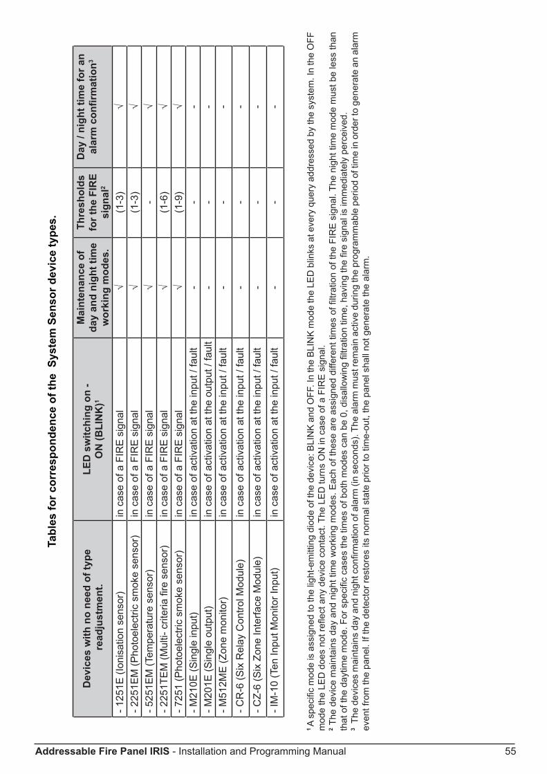
Addressable Fire Panel IRIS - Installation and Programming Manual 55
Tabl
es fo
r cor
resp
onde
nce
of th
e S
yste
m S
enso
r dev
ice
type
s.
Dev
ices
with
no
need
of t
ype
read
just
men
t.LE
D s
witc
hing
on
- O
N (B
LIN
K)1
Mai
nten
ance
of
day
and
nigh
t tim
e w
orki
ng m
odes
.
Thre
shol
ds
for t
he F
IRE
sign
al2
Day
/ ni
ght t
ime
for a
n al
arm
con
firm
atio
n3
- 125
1E (I
onis
atio
n se
nsor
)in
cas
e of
a F
IRE
sig
nal
√(1
-3)
√- 2
251E
M (P
hoto
elec
tric
smok
e se
nsor
)in
cas
e of
a F
IRE
sig
nal
√(1
-3)
√- 5
251E
M (T
empe
ratu
re s
enso
r)in
cas
e of
a F
IRE
sig
nal
√-
√- 2
251T
EM
(Mul
ti- c
riter
ia fi
re s
enso
r)in
cas
e of
a F
IRE
sig
nal
√(1
-6)
√- 7
251
(Pho
toel
ectri
c sm
oke
sens
or)
in c
ase
of a
FIR
E s
igna
l√
(1-9
)√
- M21
0E (S
ingl
e in
put)
in c
ase
of a
ctiv
atio
n at
the
inpu
t / fa
ult
--
-- M
201E
(Sin
gle
outp
ut)
in c
ase
of a
ctiv
atio
n at
the
outp
ut /
faul
t-
--
- M51
2ME
(Zon
e m
onito
r)in
cas
e of
act
ivat
ion
at th
e in
put /
faul
t-
--
- CR
-6 (S
ix R
elay
Con
trol M
odul
e)in
cas
e of
act
ivat
ion
at th
e in
put /
faul
t-
--
- CZ-
6 (S
ix Z
one
Inte
rface
Mod
ule)
in c
ase
of a
ctiv
atio
n at
the
inpu
t / fa
ult
--
-
- IM
-10
(Ten
Inpu
t Mon
itor I
nput
)in
cas
e of
act
ivat
ion
at th
e in
put /
faul
t-
--
1 A
spec
ific
mod
e is
ass
igne
d to
the
light
-em
ittin
g di
ode
of th
e de
vice
: BLI
NK
and
OFF
. In
the
BLI
NK
mod
e th
e LE
D b
links
at e
very
que
ry a
ddre
ssed
by
the
syst
em. I
n th
e O
FF
mod
e th
e LE
D d
oes
not r
eflec
t any
dev
ice
cont
act.
The
LED
turn
s O
N in
cas
e of
a F
IRE
sig
nal.
2 The
dev
ice
mai
ntai
ns d
ay a
nd n
ight
tim
e w
orki
ng m
odes
. Eac
h of
thes
e ar
e as
sign
ed d
iffer
ent t
imes
of fi
ltrat
ion
of th
e FI
RE
sig
nal.
The
nigh
t tim
e m
ode
mus
t be
less
than
th
at o
f the
day
time
mod
e. F
or s
peci
fic c
ases
the
times
of b
oth
mod
es c
an b
e 0,
dis
allo
win
g fil
tratio
n tim
e, h
avin
g th
e fir
e si
gnal
is im
med
iate
ly p
erce
ived
.3
The
devi
ces
mai
ntai
ns d
ay a
nd n
ight
con
firm
atio
n of
ala
rm (i
n se
cond
s). T
he a
larm
mus
t rem
ain
activ
e du
ring
the
prog
ram
mab
le p
erio
d of
tim
e in
ord
er to
gen
erat
e an
ala
rm
even
t fro
m th
e pa
nel.
If th
e de
tect
or re
stor
es it
s no
rmal
sta
te p
rior t
o tim
e-ou
t, th
e pa
nel s
hall
not g
ener
ate
the
alar
m.
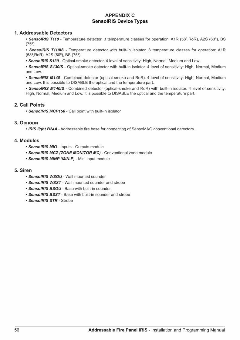
56 Addressable Fire Panel IRIS - Installation and Programming Manual
APPENDIx CSensoIRIS Device Types
1. Addressable Detectors• SensoIRIS T110 - Temperature detector. 3 temperature classes for operation: A1R (58º,RoR), A2S (60º), BS (75º).• SensoIRIS T110IS - Temperature detector with built-in isolator. 3 temperature classes for operation: A1R (58º,RoR), A2S (60º), BS (75º).• SensoIRIS S130 - Optical-smoke detector. 4 level of sensitivity: High, Normal, Medium and Low.• SensoIRIS S130IS - Optical-smoke detector with built-in isolator. 4 level of sensitivity: High, Normal, Medium and Low.• SensoIRIS M140 - Combined detector (optical-smoke and RoR). 4 level of sensitivity: High, Normal, Medium and Low. It is possible to DISABLE the optical and the temperature part.• SensoIRIS M140IS - Combined detector (optical-smoke and RoR) with built-in isolator. 4 level of sensitivity: High, Normal, Medium and Low. It is possible to DISABLE the optical and the temperature part.
2. Call Points• SensoIRIS MCP150 - Call point with built-in isolator
3. Основи• IRIS light B24A - Addressable fire base for connecting of SensoMAG conventional detectors.
4. Modules• SensoIRIS MIO - Inputs - Outputs module• SensoIRIS MCZ (ZONE MONITOR MC) - Conventional zone module• SensoIRIS MINP (MIN-P) - Mini input module
5. Siren• SensoIRIS WSOU - Wall mounted sounder• SensoIRIS WSST - Wall mounted sounder and strobe• SensoIRIS BSOU - Base with built-in sounder• SensoIRIS BSST - Base with built-in sounder and strobe• SensoIRIS STR - Strobe

Addressable Fire Panel IRIS - Installation and Programming Manual 57
Appendix D - General Menu Structure

www.teletek-electronics.comAddress: Srebarna 14А, 1407 Sofia, Bulgaria
Tel.: (+359 2) 9694 700, Fax: (+359 2) 962 52 13e-mail: [email protected]
1802
0542
_Rev
C_0
9/20
11