Embed Size (px)
Citation preview

Analog & Digital ElectronicsCourse No: PH-218
Lec-14: Feedback Amplifier
Course Instructors:
� Dr. A. P. VAJPEYI
Department of Physics,
Indian Institute of Technology Guwahati, India 1

Marks distribution: Quiz-2
3
4
5
6
7
8
Marks
Students
2
0
1
2
3
1 2 3 4 5 6 7 8 9 10 11 12
Highest: 07 ( 1 student)
Lowest: 00 ( 5 students)

Feedback Amplifier
� Feedback amplifier contains two component namely feedback circuitand amplifier circuit.
� Feedback circuit is essentially a potential divider consisting ofresistances R1 & R2
� The purpose of feedback circuit is to return a fraction of the outputvoltage to the input of the amplifier circuit.
3
Feedback circuit Feedback amplifier
21
2
1
2
RR
R
V
V
+==β
feedback fraction β

� Both negative feedback and positive feedback are used in amplifiercircuits.
� Negative feedback returns part of the output to oppose theinput, whereas in positive feedback the feedback signal aids the inputsignal.
Feedback
If Vf = 0 (there is no feedback)
i
o
S
o
V
V
V
VA ==
44
Feedback amplifier
iS VV
)( fsio VVAAVV −== of VV β=
If feedback signal Vf is connected in
series with the input, then Vi = VS- Vf
But
)( oso VVAV β−=
)1( A
A
V
VA
s
of
β+==
so AVAV =+ )1( β
Af : closed-loop gain of the amplifierA: Open-loop gain of the amplifier gain

� Negative feedback can reduce the gain of the amplifier, but it has many
advantages, such as gain stabilization, reduction of nonlinear distortion
and noise, control of input and output impedances, and extension of
bandwidth.
Advantages of Negative feedback
For negative feedback: βA > 0 ; For positive feedback: βA < 0
Feedback
5
bandwidth.
� Gain stabilization
)1( A
AAf
β+=
2)1(
1
AA
dAf
β+=
A
dA
AA
dA
f
f
)1(
1
β+=
Therefore percentage change in Af (due to variations in some circuit
parameter) is reduced by (1+βA) times compared to without feedback.

Advantages of Negative feedback
� Reduction of nonlinear distortion
(a) Open loop gain
(b) Closed loop gain
6
� Bandwidth extension

Basic Feedback Topologies
� Depending on the input signal (voltage or current) to be amplified
and form of the output (voltage or current), amplifiers can be classified into four categories. Depending on the amplifier category, one of four types of feedback structures should be used.
� Voltage series feedback (Af = Vo/Vs) – Voltage amplifier
� Voltage shunt feedback (Af = Vo/Is) – Trans-resistance amplifier
� Current series feedback (Af = Io/Vs) - Trans-conductance amplifier
7
f o s
� Current shunt feedback (Af = Io/Is) - Current amplifier
� Here voltage refers to connecting the output voltage as input to thefeedback network. Similarly current refers to connecting the output current
as input to the feedback network.
�Series refers to connecting the feedback signal in series with the input
voltage; Shunt refers to connecting the feedback signal in shunt (parallel)with an input current source.
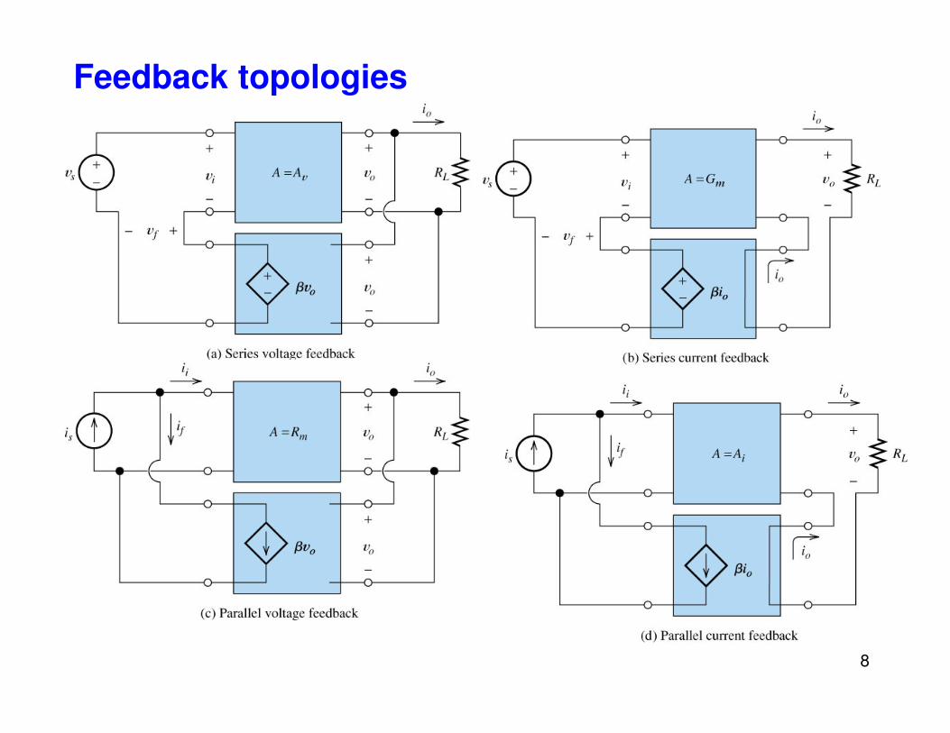
Feedback topologies
8

Feedback topologies: Voltage Shunt Feedback
� Output resistance of the
amplifier and output resistance
of the feedback circuit are inparallel hence effective outputresistance of the feedback
amplifier will reduce.
�Similarly overall inputresistance of the feedback
amplifier will reduce due toparallel connection of amplifier
� Since effective input resistance is small hence input should be a current. �(for ideal voltage source – input resistance is very high compare to internal source resistance, if not then, lot of voltage will be dropped at internal
source resistance and voltage source won’t be a ideal voltage source )
� Effective output resistance is also small compare to the resistance of
amplifier without feedback hence less voltage will drop at Ro-eff and most of the voltage occurs at RL. Hence output ckt will behave like a voltage source. Thus voltage shunt feedback ckt behave like a current controlled voltage source.
parallel connection of amplifierand feedback resistor.
9

Feedback topologies: Voltage Shunt Feedback
Voltage Gain :
)1
(
)1(
)(
)(
A
A
I
VA
VAAI
VVIA
VI
IIAiIAV
of
oS
ooS
of
fSo
β
β
β
β
+==
+=
=−
⋅=
−=⋅=
10
1 AIS
fβ+
Input Impedance :
)1(
)
in
in
A
rZ
AII
rI
VI
rI
II
V
I
VZ
i
ii
ii
oi
ii
fi
i
S
i
β
ββ
+=
+
⋅=
+
⋅=
+==
Output Impedance :
o
oo
o
ioo
ofi
o
oV
r
AVV
r
AIVI
VII
I
VZ
S
β
β
+=
−=
−=−=
==
port,output from
port,input from
| 0out
)1(out
A
r
I
VZ o
o
o
β+==

Feedback topologies: Voltage Series Feedback
� Output resistance of the amplifier and output resistance of the feedbackcircuit are in parallel hence effective output resistance of the feedback
amplifier will reduce.
�Input resistance of the amplifier and feedback network are in series
hence effective input resistance will increase.
11

Feedback topologies: Voltage Series Feedback
Voltage Gain :
)1
(
)1(
)(
)(
A
A
V
VA
VAAV
VVVA
VV
VVAiVAV
of
oS
ooS
of
fSo
β
β
β
β
+==
+=
=−
⋅=
−=⋅=
Input Impedance :
)1()1(
in
in
ArI
AVZ
I
AVV
I
VV
I
VV
I
VZ
i
S
i
S
ii
S
oi
S
fi
S
S
ββ
ββ
+=+
=
+=
+=
+==
Output Impedance :
β
β
β
⋅⋅+
⋅−=
==⋅+
⋅−=
==
VAV
VV
VVV
r
VAVI
I
VZ
oi
Soi
o
ioo
o
oVS
0
| 0out
1212
1 AVS
fβ+
IS
β
β
⋅+==
⋅⋅+=
A
r
I
VZ
r
VAVI
o
o
o
o
ooo
1out

Feedback topologies: Current Series Feedback
� Output resistance of the amplifier and output resistance of the feedback
circuit are in series hence effective output resistance of the feedback amplifierwill increase.
�Input resistance of the amplifier and feedback network are in series henceeffective input resistance will increase.
� Thus Current series feedback circuit behave like a voltage controlled currentsource. 13

+
Basic amplifierIS
+
−Vi ri
Vf=βIo
ro
AVi
Iο
VS
Vο+−
)1
(
)1(
)(
)(
A
A
V
IA
IAAV
IIVA
IV
VVAiVAI
S
of
oS
ooS
of
fSo
β
β
β
β
+==
+=
=−
⋅=
−=⋅=
Voltage Gain :
Feedback topologies: Current Series Feedback
14
+−
Feedback network
Vf=βIo 1 AVS β+
Input Impedance :
)1()1(
in
in
ArI
AVZ
I
AVV
I
VV
I
VV
I
VZ
i
S
i
S
ii
S
oi
S
fi
S
S
ββ
ββ
+=+
=
+=
+=
+==
Output Impedance :
o
ioo
o
oV
r
VAVI
I
VZ
S
⋅−=== ;| 0out
β⋅+==
A
r
I
VZ o
o
o
1out
o
ooo
Sfi
r
IAVI
VVV
⋅⋅+=
==+
β
0

Feedback topologies: Current Shunt Feedback
�Effective output resistance of the feedback amplifier will increase.
�Effective input resistance will decrease.
� Thus current shunt feedback circuit behave like a current controlledcurrent source.
15