Embed Size (px)
Citation preview
Pub. 42004-484E
GAI-Tronics Corporation 400 E. Wyomissing Ave. Mohnton, PA 19540 USA 610-777-1374 800-492-1212 Fax: 610-796-5954
VISIT WWW.GAI-TRONICS.COM FOR PRODUCT LITERATURE AND MANUALS
ATTENTION! Replacing an existing Model 295F or 295W with this telephone (Model 295-001F or 295-001W) requires removing the existing 48 V dc power supply and replacing it with the 5 V dc power supply included with this telephone (or other 5 V dc source).
Connecting 48 V dc to this telephone will cause severe damage.
Pub. 42004-484E
GAI-Tronics Corporation 400 E. Wyomissing Ave. Mohnton, PA 19540 USA 610-777-1374 800-492-1212 Fax: 610-796-5954
VISIT WWW.GAI-TRONICS.COM FOR PRODUCT LITERATURE AND MANUALS
G A I - T R O N I C S ® C O R P O R A T I O N A H U B B E L L C O M P A N Y
Analog Clean Phone® Telephones T A B L E O F C O N T E N T S
Confidentiality Notice .....................................................................................................................4
Product Overview ............................................................................................................................4
Features .................................................................................................................................................... 5
Auto-Dial Buttons ................................................................................................................................... 5
Flash Button ............................................................................................................................................ 5
Auto-Answer ............................................................................................................................................ 5
Models ...................................................................................................................................................... 6
Telephone Management Application (TMA) ....................................................................................... 6
Operation .........................................................................................................................................7
Placing an Autodial Call from an Analog Clean Phone® .................................................................... 7
Placing a General Telephone Call ......................................................................................................... 7
Receiving a Call ....................................................................................................................................... 7
Installation ......................................................................................................................................8
General Information ............................................................................................................................... 8
Safety Guidelines ..................................................................................................................................... 8
General Installation Guidelines ............................................................................................................. 9
Station Placement .................................................................................................................................... 9
Model 295-001F Clean Phone® ............................................................................................................ 10
Model 295-001W Clean Phone® ........................................................................................................... 14
External Power ...................................................................................................................................... 16
Setup ..............................................................................................................................................17
Hardware Configuration ...................................................................................................................... 17 Auto-answer Configuration ................................................................................................................................ 17 Polarity Configuration ........................................................................................................................................ 17 DTMF Gain Select Configuration ....................................................................................................................... 17 Password Enable Configuration .......................................................................................................................... 18 Command Select Configuration .......................................................................................................................... 18 Low-Power Mode Configuration ........................................................................................................................ 18 Hardware Settings ............................................................................................................................................... 18
Auxiliary Outputs ................................................................................................................................. 19
Auxiliary Output Control ..................................................................................................................... 19
Standard Mode Programming ......................................................................................................21
Set-up Sequence .................................................................................................................................... 21 Remote ................................................................................................................................................................ 21
PUB. 42004-484E
ANALOG CLEAN PHONE®
TELEPHONES PAGE iii of 33
GAI-Tronics Corporation 400 E. Wyomissing Ave. Mohnton, PA 19540 USA 610-777-1374 800-492-1212 Fax: 610-796-5954
VISIT WWW.GAI-TRONICS.COM FOR PRODUCT LITERATURE AND MANUALS
Local ................................................................................................................................................................... 21
Programming Sequence ........................................................................................................................ 22
Password Disabled Programming ....................................................................................................... 22
Programming Sequences ...................................................................................................................... 23 Dialing Options ................................................................................................................................................... 23 Password Protection ............................................................................................................................................ 25 Auto-Answer Alert Feature ................................................................................................................................. 25 Off-Hook Ringing ............................................................................................................................................... 26 Disconnect Options ............................................................................................................................................. 27 Extended Control Output Operation ................................................................................................................... 27 Output 4 Control Setup ....................................................................................................................................... 28 Early Microphone Option ................................................................................................................................... 29
SMART Mode Programming........................................................................................................31
Maintenance ..................................................................................................................................31
General Information ............................................................................................................................. 31
Service .................................................................................................................................................... 31
Specifications ................................................................................................................................32
Replacement Parts and Accessories .................................................................................................... 33
Pub. 42004-484E
GAI-Tronics Corporation 400 E. Wyomissing Ave. Mohnton, PA 19540 USA 610-777-1374 800-492-1212 Fax: 610-796-5954
VISIT WWW.GAI-TRONICS.COM FOR PRODUCT LITERATURE AND MANUALS
G A I - T R O N I C S ® C O R P O R A T I O N A H U B B E L L C O M P A N Y
Analog Clean Phone® Telephones
Confidentiality Notice This manual is provided solely as an installation, operation, and maintenance guide and contains sensitive business and technical information that is confidential and proprietary to GAI-Tronics. GAI-Tronics retains all intellectual property and other rights in or to the information contained herein, and such information may only be used in connection with the operation of your GAI-Tronics product or system. This manual may not be disclosed in any form, in whole or in part, directly or indirectly, to any third party.
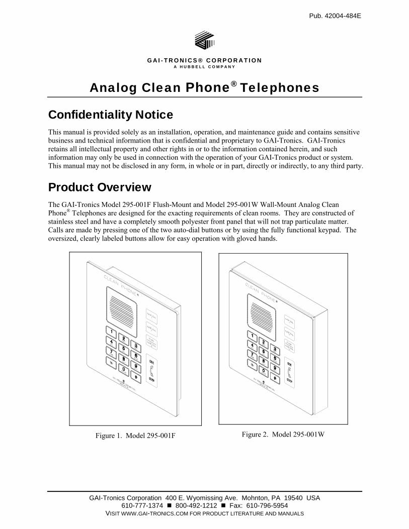
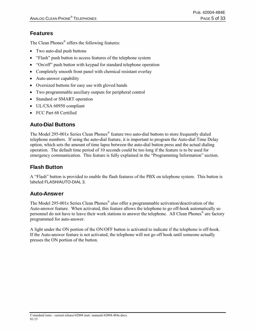
Product Overview The GAI-Tronics Model 295-001F Flush-Mount and Model 295-001W Wall-Mount Analog Clean Phone® Telephones are designed for the exacting requirements of clean rooms. They are constructed of stainless steel and have a completely smooth polyester front panel that will not trap particulate matter. Calls are made by pressing one of the two auto-dial buttons or by using the fully functional keypad. The oversized, clearly labeled buttons allow for easy operation with gloved hands.
Figure 1. Model 295-001F
Figure 2. Model 295-001W
PUB. 42004-484E
ANALOG CLEAN PHONE®
TELEPHONES PAGE 5 of 33
f:\standard ioms - current release\42004 instr. manuals\42004-484e.docx 01/15
Features The Clean Phones® offers the following features:
Two auto-dial push buttons
“Flash” push button to access features of the telephone system
“On/off” push button with keypad for standard telephone operation
Completely smooth front panel with chemical resistant overlay
Auto-answer capability
Oversized buttons for easy use with gloved hands
Two programmable auxiliary outputs for peripheral control
Standard or SMART operation
UL/CSA 60950 compliant
FCC Part 68 Certified
Auto-Dial Buttons The Model 295-001x Series Clean Phones® feature two auto-dial buttons to store frequently dialed telephone numbers. If using the auto-dial feature, it is important to program the Auto-dial Time Delay option, which sets the amount of time lapse between the auto-dial button press and the actual dialing operation. The default time period of 10 seconds could be too long if the feature is to be used for emergency communication. This feature is fully explained in the “Programming Information” section.
Flash Button A “Flash” button is provided to enable the flash features of the PBX on telephone system. This button is labeled FLASH/AUTO-DIAL 3.
Auto-Answer The Model 295-001x Series Clean Phones® also offer a programmable activation/deactivation of the Auto-answer feature. When activated, this feature allows the telephone to go off-hook automatically so personnel do not have to leave their work stations to answer the telephone. All Clean Phones® are factory programmed for auto-answer.
A light under the ON portion of the ON/OFF button is activated to indicate if the telephone is off-hook. If the Auto-answer feature is not activated, the telephone will not go off hook until someone actually presses the ON portion of the button.
PUB. 42004-484E
ANALOG CLEAN PHONE®
TELEPHONES PAGE 6 of 33
f:\standard ioms - current release\42004 instr. manuals\42004-484e.docx 01/15
Models The following analog Clean Phone® Telephones are detailed in this manual:
Table 1. Model Chart
Model Description
295-001W Surface-Mount Analog Telephone including a stainless steel front panel with polyester overlay, two autodial buttons and a “flash” button, hookswitch push button (on/off), off-hook indicator, keypad, and stainless steel surface-mount enclosure.
295-001F Flush-Mount Analog Telephone including stainless steel front panel with polyester overlay; two autodial buttons and a “flash” button, hookswitch push button (on/off), off-hook indicator, keypad, and stainless steel mounting bracket.
Telephone Management Application (TMA) GAI-Tronics’ TMA software is a maintenance data collection and reporting tool that allows users to view and report the health of the Clean Phone® Emergency Telephones. Clean Phone® Telephones can function with or without the TMA software application installed. The decision to use TMA can be made at any time and is not needed for telephone operation. Installation of TMA is not required until system monitoring is desired.
When used with TMA, each telephone will typically be polled to determine the health of the unit and report the following:
Stuck push buttons
Microphone failure
Speaker failure
Microprocessor health
Line interrupt (power)
The basic TMA package (Model 12509-042) includes a single line transceiver for polling a single telephone at a time. With each telephone requiring approximately 90 seconds to relay its health status to TMA, the ability to poll multiple telephones simultaneously may become very important in larger systems. A TMA expansion kit (Model 12509-043) is available and is required for each additional connected telephone line, with a maximum of eight lines allowed. This allows a maximum of eight telephones to be polled simultaneously. A dedicated PC is strongly recommended for TMA operation.
A dedicated telephone line per Clean Phone® Telephone is required when using TMA in its typical “polling” operation. Although it is not recommended, Clean Phone® Telephones can share a telephone line with the understanding that if two or more telephones are put into use simultaneously, the line current could drop sufficiently to disconnect the telephone call completely. This will depend on the line current, the length of the cable run, and the condition of the telephone cable. When sharing a telephone line using TMA, the telephone must be scheduled to “call-in” instead of being polled by TMA.
TMA users can schedule auto-dial maintenance calls to alert maintenance personnel of any unusual sensor or fault conditions that exist. Clean Phone® Telephones can also be programmed to generate an auto-dial maintenance call when certain sensor events are discovered. Access to the Clean Phone® Telephone settings is restricted through the use of the maintenance access PIN, which should be disclosed only to trained maintenance personnel.
PUB. 42004-484E
ANALOG CLEAN PHONE®
TELEPHONES PAGE 7 of 33
f:\standard ioms - current release\42004 instr. manuals\42004-484e.docx 01/15
Operation Placing an Autodial Call from an Analog Clean Phone® To place an autodial call:
1. Press the desired autodial push button to place an immediate call to a preprogrammed number.
2. When the call is connected, the hookswitch indicator will light.
3. The call is terminated by the following: pressing the ON/OFF push button, or the receiving caller hanging up, or the defined timeout of the call duration.
Placing a General Telephone Call To place a general telephone call:
1. Press the ON/OFF push button.
2. Wait for the dial tone.
3. Use the keypad to dial the desired number.
4. When the call is connected, the “off-hook” indicator will light.
5. The call is terminated by one of the following methods: pressing the ON/OFF push button, the receiving caller hanging up, call duration timeout.
Receiving a Call When a Clean Phone® is called, the unit automatically goes off-hook (auto-answer) and a conversation can take place. This is the default mode operation. The Clean Phone® can be programmed for manual answer, if desired. Refer to the Off-Hook Ringing setting.
PUB. 42004-484E
ANALOG CLEAN PHONE®
TELEPHONES PAGE 8 of 33
f:\standard ioms - current release\42004 instr. manuals\42004-484e.docx 01/15
Installation General Information
WARNING This product can contain hazardous voltages. Always remove power to this station and any associated equipment before beginning any installation.
CAUTION Do not install this equipment in areas other than those indicated on the approval standards listing in the “Specifications” section of this manual. Such installation may cause a safety hazard and consequent injury or property damage.
Install equipment without modification and according to all applicable local and national electrical codes. Consult the National Electrical Code (NFPA 70), Canadian Standards Association (CSA 22.1), and local codes for specific requirements regarding your installation. Class 2 circuit wiring must be performed in accordance with NEC 725.55.
Safety Guidelines When installing any GAI-Tronics telephone equipment, please adhere to the following guidelines to ensure the safety of all personnel:
Do not install telephone wiring during a lightning storm.
Electrostatic Discharge (ESD) Protection: Your telephone may have an earth ground terminal provision. If so, ensure that it is connected to ground in accordance with all local safety regulations and the National Electrical Code (NEC). Grounding has to be ensured for safe and stable communications. Do not use long and coiled ground wires. Trim ground wires to the required length. Use a star configuration whenever possible. Please note proper grounding does not eliminate the need for lightning protection for the telephone or the telephone system.
Install a UL Listed lightning arrestor on any telephone installed where the telephone or telephone cable is at risk of being exposed to lightning strikes. The lightning arrestor must be installed as close to the telephone as possible to maximize the protection. It must not be installed within the enclosure supplied with the phone.
Do not install telephone jacks in wet locations unless the jack is specifically designed for wet locations.
Do not touch uninsulated telephone wires or terminals unless the telephone line has been disconnected at the network interface.
PUB. 42004-484E
ANALOG CLEAN PHONE®
TELEPHONES PAGE 9 of 33
f:\standard ioms - current release\42004 instr. manuals\42004-484e.docx 01/15
General Installation Guidelines As previously noted, the preferred system configuration is a dedicated telephone line per Clean Phone® Telephone. This is an actual requirement when using TMA in its typical “polling” operation.
Although it is not recommended, a Clean Phone® Telephone can share a telephone line with another Clean Phone® Telephone with the understanding that if two or more telephones are put into use simultaneously the line current could drop sufficiently to disconnect the telephone call completely. Additional “line sharing” or “party line” configuration issues could include sporadic telephone operation, difficulties with programming, or premature disconnection of calls. Special system features (voice mail, call waiting, etc.) could also create problems if not disabled. Successful shared line operation will depend on the line current, the length of the cable run, and the condition of the telephone cable.
NOTE: A Clean Phone® Telephone should never be installed on the same telephone line as any other (non-Clean Phone®) telephone type.
When sharing a telephone line using TMA, the telephone must be scheduled to “call-in” instead of being polled by TMA.
Station Placement To prevent feedback problems in the system, volume settings and station placement must be taken into consideration. Unpleasant feedback problems can be reduced by:
Pointing the telephone away from other telephones located nearby
Reducing volume levels
Feedback problems can be avoided by installing each analog Clean Phone® in a separate room and wall.
PUB. 42004-484E
ANALOG CLEAN PHONE®
TELEPHONES PAGE 10 of 33
f:\standard ioms - current release\42004 instr. manuals\42004-484e.docx 01/15
Model 295-001F Clean Phone® The mounting and wiring instructions for the Model 295-001F Clean Phone® are as follows:
1. Remove the front panel from the back bracket.
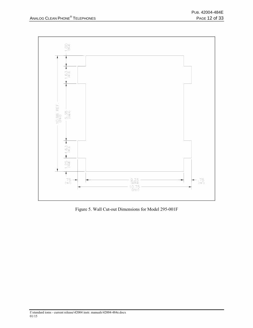
2. Refer to Figure 5 on page 12 for cut-out details. Use the cut-out dimensions as a guide to mark the wall, and make the required cuts.
3. Place the modular RJ11 jack provided in the lower right corner of the back bracket.
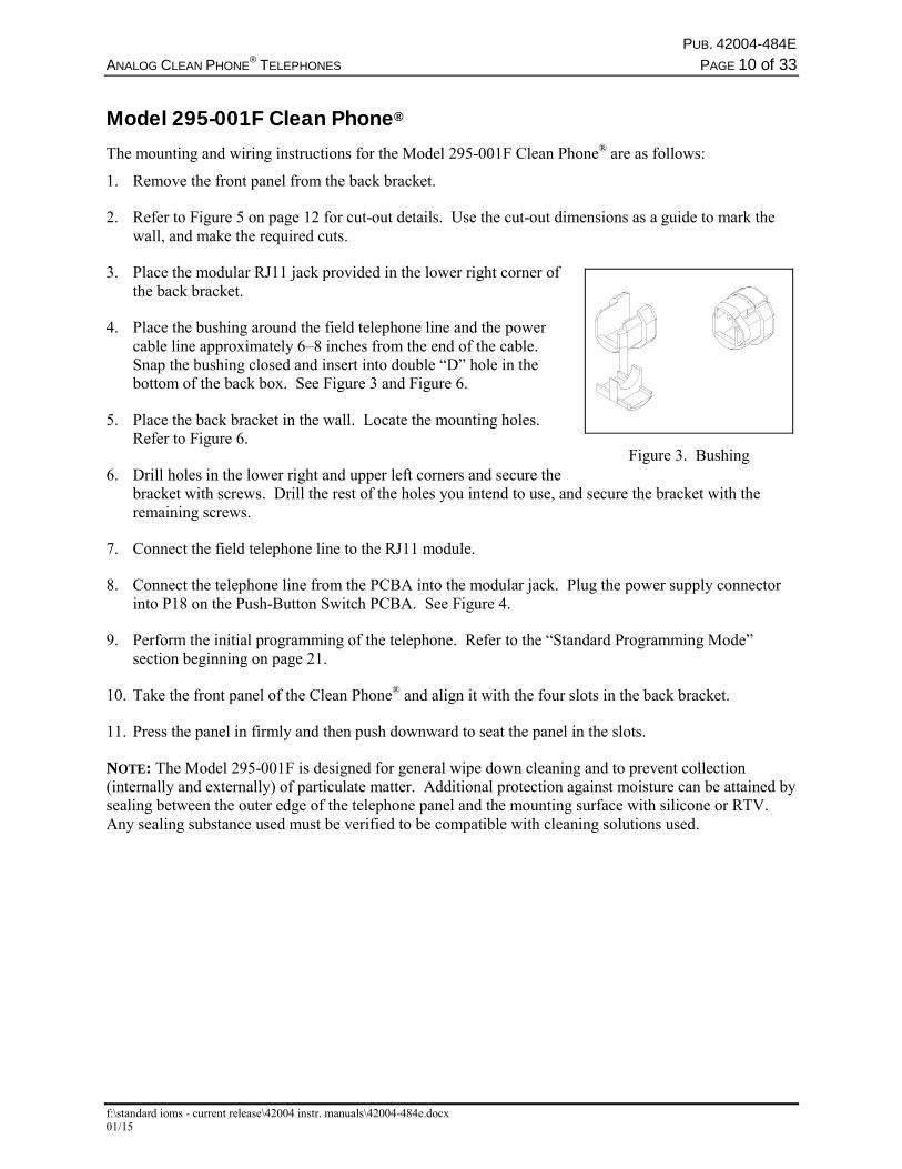
4. Place the bushing around the field telephone line and the power cable line approximately 6–8 inches from the end of the cable. Snap the bushing closed and insert into double “D” hole in the bottom of the back box. See Figure 3 and Figure 6.
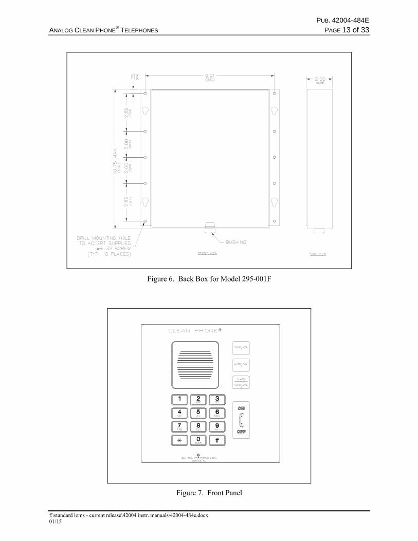
5. Place the back bracket in the wall. Locate the mounting holes. Refer to Figure 6.
6. Drill holes in the lower right and upper left corners and secure the bracket with screws. Drill the rest of the holes you intend to use, and secure the bracket with the remaining screws.
7. Connect the field telephone line to the RJ11 module.
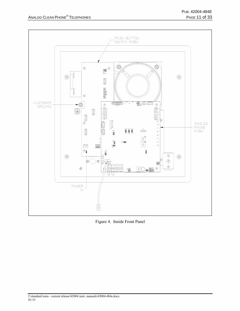
8. Connect the telephone line from the PCBA into the modular jack. Plug the power supply connector into P18 on the Push-Button Switch PCBA. See Figure 4.
9. Perform the initial programming of the telephone. Refer to the “Standard Programming Mode” section beginning on page 21.
10. Take the front panel of the Clean Phone® and align it with the four slots in the back bracket.
11. Press the panel in firmly and then push downward to seat the panel in the slots.
NOTE: The Model 295-001F is designed for general wipe down cleaning and to prevent collection (internally and externally) of particulate matter. Additional protection against moisture can be attained by sealing between the outer edge of the telephone panel and the mounting surface with silicone or RTV. Any sealing substance used must be verified to be compatible with cleaning solutions used.
Figure 3. Bushing
PUB. 42004-484E
ANALOG CLEAN PHONE®
TELEPHONES PAGE 11 of 33
f:\standard ioms - current release\42004 instr. manuals\42004-484e.docx 01/15
Figure 4. Inside Front Panel
PUB. 42004-484E
ANALOG CLEAN PHONE®
TELEPHONES PAGE 12 of 33
f:\standard ioms - current release\42004 instr. manuals\42004-484e.docx 01/15
Figure 5. Wall Cut-out Dimensions for Model 295-001F
PUB. 42004-484E
ANALOG CLEAN PHONE®
TELEPHONES PAGE 13 of 33
f:\standard ioms - current release\42004 instr. manuals\42004-484e.docx 01/15
Figure 6. Back Box for Model 295-001F
Figure 7. Front Panel
PUB. 42004-484E
ANALOG CLEAN PHONE®
TELEPHONES PAGE 14 of 33
f:\standard ioms - current release\42004 instr. manuals\42004-484e.docx 01/15
Model 295-001W Clean Phone® The mounting and wiring instructions for the Model 295-001W Clean Phone® are as follows:
1. Remove the front panel from the back box.
2. Place the modular RJ11 jack provided in the lower right corner of the back box.
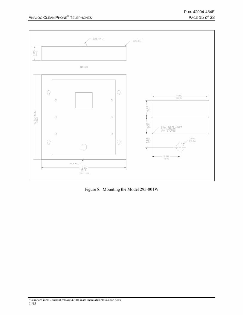
3. Using the back box as a template, drill holes in the lower right and upper left corners of the mounting surface and secure the back box with screws. Drill the holes in the pattern shown in Figure 8.
4. Place the bushing around the field telephone line and power cable approximately 8 inches from the end of the cable. Snap the bushing closed and insert into the “D” hole in the back of the back box. See Figure 3 and Figure 8.
5. Secure the back box to the mounting surface.
6. Connect the field telephone line to the RJ11 module.
7. Plug both the telephone line from the PCBA and the field telephone line into the modular jack. Plug the power supply connector into P18 on the Push-Button Switch PCBA. Refer to Figure 4.
8. Perform the initial programming of the telephone. Refer to the “Standard Programming Mode” section beginning on page 21.
9. Take the front panel of the Clean Phone® and align it with the four slots in the back box.
10. Press the panel in firmly, and then push downward to seat the panel in the slots.
NOTE: The Model 295-001W is designed for general wipe down cleaning and to prevent collection (internally and externally) of particulate matter.
PUB. 42004-484E
ANALOG CLEAN PHONE®
TELEPHONES PAGE 15 of 33
f:\standard ioms - current release\42004 instr. manuals\42004-484e.docx 01/15
Figure 8. Mounting the Model 295-001W
PUB. 42004-484E
ANALOG CLEAN PHONE®
TELEPHONES PAGE 16 of 33
f:\standard ioms - current release\42004 instr. manuals\42004-484e.docx 01/15
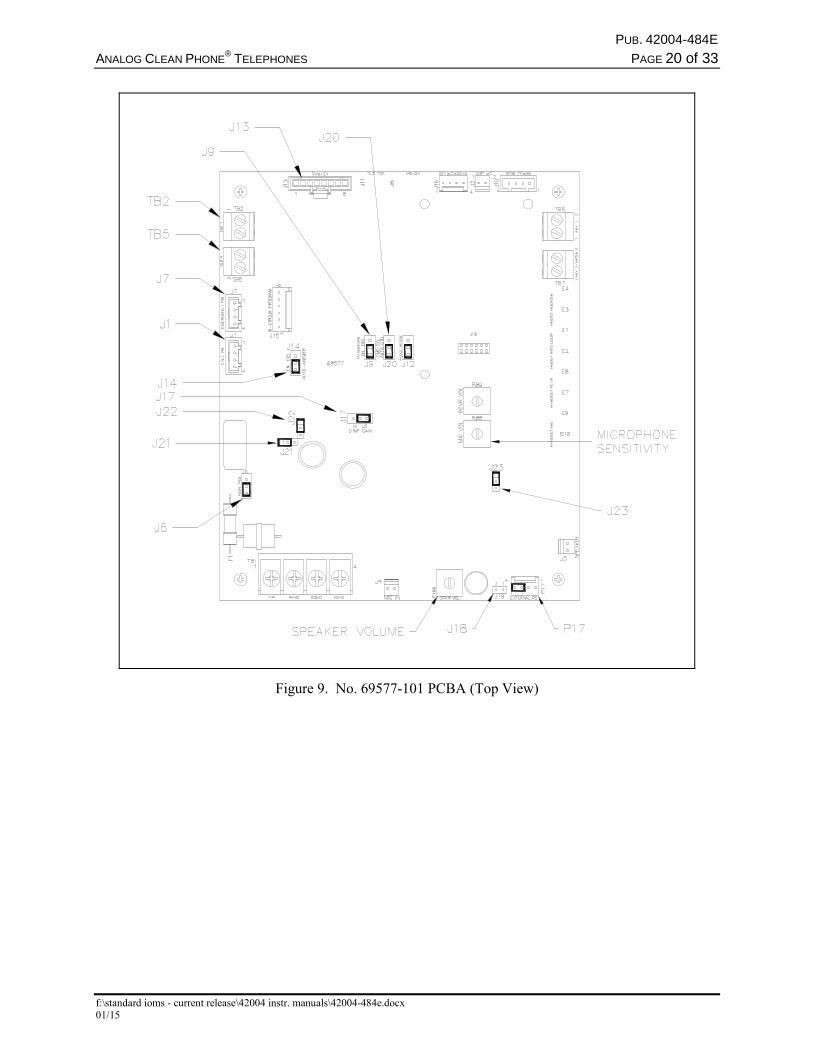
External Power The Plug-in Power Supply provided with each telephone requires 100–240 V ac input to provide a 5 V dc output to the unit. The power supply’s connectorized, 4-foot power cable plugs into P18 on the Push Button Switch PCBA. Refer to Figure 4 on page 11, and see Figure 9 on page 20 for jumper locations.
The No. 40411-005 Power Supply is provided with a 4-foot cord for connecting the Clean Phone®. Additional wire may be spliced to the existing power supply cord to obtain the desired distance to the telephone.
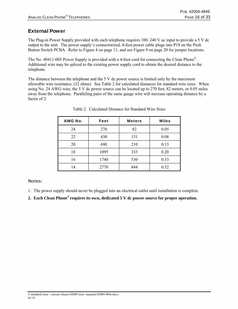
The distance between the telephone and the 5 V dc power source is limited only by the maximum allowable wire resistance, (32 ohms). See Table 2 for calculated distances for standard wire sizes. When using No. 24 AWG wire, the 5 V dc power source can be located up to 270 feet, 82 meters, or 0.05 miles away from the telephone. Paralleling pairs of the same gauge wire will increase operating distance by a factor of 2.
Table 2. Calculated Distance for Standard Wire Sizes
AWG No. Feet Meters Miles
24 270 82 0.05
22 430 131 0.08
20 690 210 0.13
18 1095 333 0.20
16 1740 530 0.33
14 2770 844 0.52
NOTES:
1. The power supply should never be plugged into an electrical outlet until installation is complete.
2. Each Clean Phone® requires its own, dedicated 5 V dc power source for proper operation.
PUB. 42004-484E
ANALOG CLEAN PHONE®
TELEPHONES PAGE 17 of 33
f:\standard ioms - current release\42004 instr. manuals\42004-484e.docx 01/15
Setup Hardware Configuration The hardware configuration options are explained in detail in the following sections, and the necessary jumper settings are identified to enable or disable each option. Reading each section and recording the selected options prior to making the necessary changes is recommended. Create a record of your settings using Table 3 on page 18. See Figure 9 on page 20 for the jumper locations.
Auto-answer Configuration
Factory Setting: Auto-answer feature enabled
The Auto-answer feature enables or disables the automatic answering of an incoming call, which allows TMA to monitor the health of this telephone via polling with SMART operation enabled. When the Auto-answer feature is enabled, the telephone automatically answers the call and attempts to communicate with TMA. If the caller is not TMA, the telephone automatically transitions to a standard two-way communication.
Enable: J14 jumper in position EN.
Disable: J14 jumper in position DIS (Do not use this setting except under the direction of GAI-Tronics personnel.)
NOTE: The Auto-answer feature must be enabled to allow the GAI-Tronics Telephone Management Application PC to contact the telephone or to allow remote Touch Tone programming.
Polarity Configuration
Factory Setting: Non-polarity sensitive
This telephone can be configured to be polarity or non-polarity sensitive. With the non-polarized setting, the telephone operates regardless of tip and ring polarity. With the polarized setting, the telephone only operates with the telephone line’s positive terminal connected to the tip. Use the Polarity Sensitive setting to allow a line voltage reversal disconnect signal to disconnect the call.
Non-polarity Sensitive: J6 jumper in position NON.
Polarity Sensitive: J6 jumper on in position POL.
DTMF Gain Select Configuration
Factory Setting: Low Gain selected.
Two gain selections are available in the DTMF detection circuit. In most installations, the low gain setting is recommended. The high gain setting may be necessary if the telephone is not responding to manual or TMA-generated DTMF commands.
Low Gain Selected: J17 jumper in position LO.
High Gain Selected: J17 jumper in position HI.
PUB. 42004-484E
ANALOG CLEAN PHONE®
TELEPHONES PAGE 18 of 33
f:\standard ioms - current release\42004 instr. manuals\42004-484e.docx 01/15
Password Enable Configuration
Factory Setting: Password Enabled
This telephone can be configured to enable or disable the password protection for programming (Standard Mode only). This can be useful when initially programming the telephones.
Password Enabled: J9 jumper in position EN.
Password Disabled: J9 jumper in position DIS.
Command Select Configuration
Factory Setting: Auto
The purpose of J20 is to enable or disable automatic transition to SMART operation. With this jumper in the standard position, SMART operation is disabled.
SMART Operation Enabled (Auto): J20 jumper in position AUTO.
SMART Operation Disabled (Standard): J20 jumper in position STD.
Low-Power Mode Configuration
Factory Setting: Low-Power Mode Disabled
For some installations in which only minimal loop current is available, the performance of the telephone may be improved by enabling this feature. Symptoms of minimal loop current may include low speaker volume and/or momentary muting of audio. In the majority of applications, however, the low-power mode should be disabled. The low-power mode is enabled by installing the following three jumpers: J21, J22, and J23.
Low-Power Mode Enabled: Jumpers installed at J21, J22, and J23.
Low-Power Mode Disabled: Jumpers NOT installed at J21, J22, and J23.
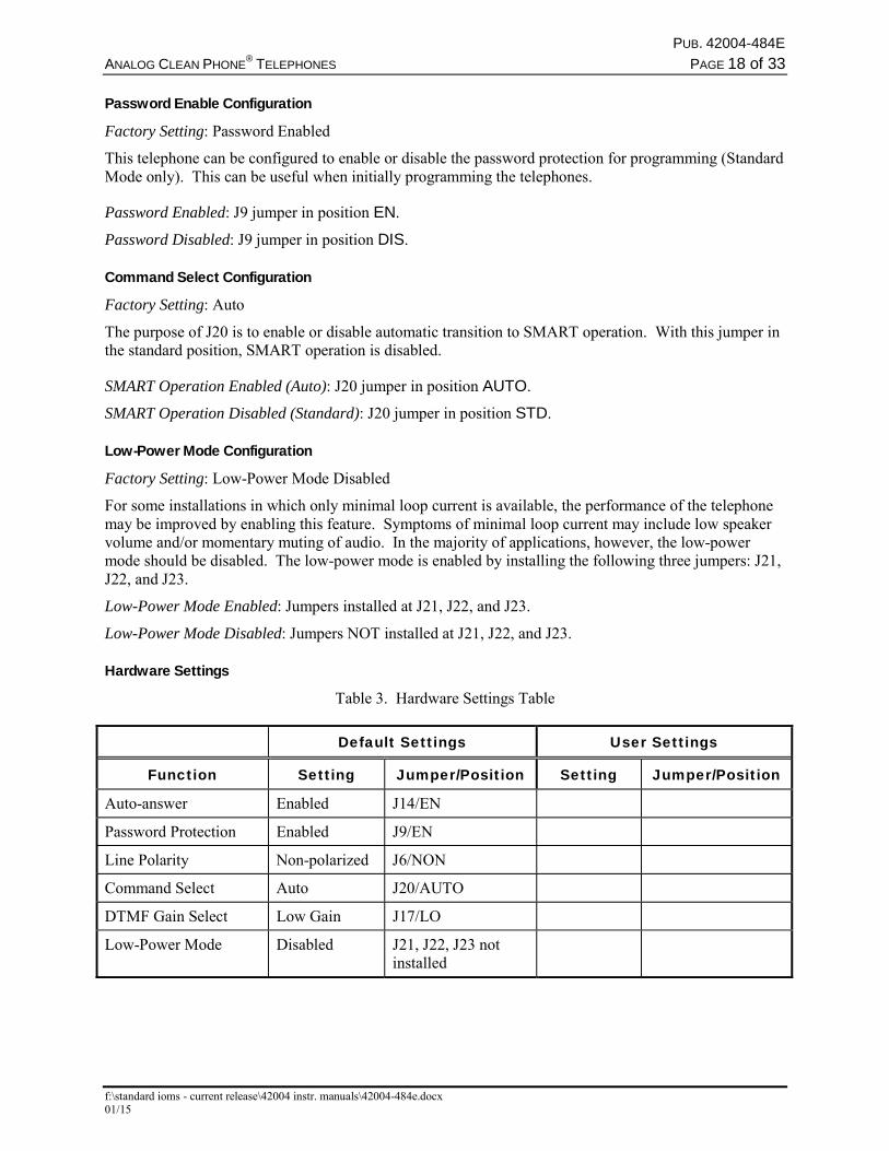
Hardware Settings
Table 3. Hardware Settings Table
Default Settings User Settings
Function Setting Jumper/Position Setting Jumper/Position
Auto-answer Enabled J14/EN
Password Protection Enabled J9/EN
Line Polarity Non-polarized J6/NON
Command Select Auto J20/AUTO
DTMF Gain Select Low Gain J17/LO
Low-Power Mode Disabled J21, J22, J23 not installed
PUB. 42004-484E
ANALOG CLEAN PHONE®
TELEPHONES PAGE 19 of 33
f:\standard ioms - current release\42004 instr. manuals\42004-484e.docx 01/15
Auxiliary Outputs Each telephone includes two isolated solid state switches capable of switching a maximum of 48 V dc, 125 mA or 28 VRMS ac, 80RMS mA. TB2 (OUT1) and TB5 (OUT4) on the emergency telephone PCBA provides the connections for the auxiliary outputs. Refer to Figure 9 for the location of TB2 and TB5.
Auxiliary Output Control As previously noted, each Analog Clean Phone® is capable of providing two isolated control outputs in the form of a dry (volt-free) contact closure rated at 125 mA.
Output 1 connects to TB2 on the telephone’s PCBA (refer to Figure 9). This output closes when the AUTO-DIAL1 push button is pressed and remains in that state for the duration of the telephone call.
NOTE: Output 1 can be programmed to remain closed for up to 255 minutes (in 1 minute increments) after the call ends. This output extension can be deactivated via an external switch or by pressing “*921” on the keypad of the called telephone. The Clean Phone® will acknowledge acceptance of this deactivation command with a short beep. If the beep is not initially received, retry the command.
Output 4, connects to TB5 on the telephone’s PCBA (adjacent to TB2). This output can be remotely controlled via an appropriate DTMF command. This remote control output could be used to activate or control a door latch, gate relay solenoid, alarm, etc. from the called party location.
PUB. 42004-484E
ANALOG CLEAN PHONE®
TELEPHONES PAGE 20 of 33
f:\standard ioms - current release\42004 instr. manuals\42004-484e.docx 01/15
Figure 9. No. 69577-101 PCBA (Top View)
PUB. 42004-484E
ANALOG CLEAN PHONE®
TELEPHONES PAGE 21 of 33
f:\standard ioms - current release\42004 instr. manuals\42004-484e.docx 01/15
Standard Mode Programming Prior to programming the Clean Phone® telephones read the “Programming” section in its entirety, record the desired key sequences and jumper settings.
The programming has been divided into two distinct subsections; “Standard Mode” and “SMART Mode.” Standard Mode programming is used if the telephone system installation does not include the TMA (Telephone Management Application) PC software. With TMA installed, the telephones will be monitored and the SMART Mode programming should be used. Normal telephone operation is identical in either mode of operation.
Each Clean Phone® telephone is factory-programmed to receive Standard Mode commands. Factory-default settings are shown in Table 12 on page 30.
Set-up Sequence Set up each Clean Phone® telephone for either “remote” access programming or for “local” access programming.
Remote
Ensure that the auto-answer feature is enabled. (Refer to page 17.) Using a touch-tone telephone, call the Clean Phone® telephone. The telephone will automatically answer the call and generate a splash tone (low to high sequence), followed by a success tone (short beep).
Local
Press the ON/OFF push button. When dial tone is heard from the speaker, simultaneously press the “1” and “#” keypad buttons. The Clean Phone® telephone will generate a splash tone (low to high sequence), followed by a success tone (short beep).
PUB. 42004-484E
ANALOG CLEAN PHONE®
TELEPHONES PAGE 22 of 33
f:\standard ioms - current release\42004 instr. manuals\42004-484e.docx 01/15
Programming Sequence The following command sequences are common to both “remote” and “local” programming and are used to configure the telephone to the desired operating parameters.
1. Dial the factory-default password 2468 (or appropriate customer-selected password). A success tone (short beep) is generated to indicate that “standard” programming mode has been accessed.
2. After hearing the password success tone, begin entering each desired programming key sequence. Refer to the “Programming Sequences” section on page 22. A success tone (short beep) is generated each time a new key sequence is accepted. An error tone (two low tones) is generated to indicate an error. If an error tone is generated, verify the key sequence and enter the sequence again.
3. To terminate the programming call:
a. Remote – Place the programming telephone on hook. The Clean Phone® telephone will automatically end the programming call within 20 seconds.
b. Local – Press the ON/OFF push button to end the call.
NOTES:
1. The Clean Phone® telephone will automatically time out and disconnect if 20 seconds elapses between digit entries, or if an invalid password is entered.
2. If DTMF digits have not been dialed within 3 seconds of the first success tone, the telephone will exit programming mode and revert to a standard voice call.
3. If the password success tone is not generated, the telephone has failed to recognize the password. Therefore, the telephone must then be programmed with the password disabled. Refer to the “Password Disabled Programming” section on page 22.
Password Disabled Programming The programmable features of the Clean Phone® telephones are protected by a factory default or user specified password, as previously described. Situations may arise when a setting change is required but the password is forgotten or unknown. To permit continued programming support in this situation, converting to Password Disable Programming may be necessary and is described as follows:
1. Access the telephone’s PCBA and disable the password protection feature by changing jumper J9 to the “DIS” position.
2. Confirm the auto-answer feature is enabled (jumper J14 should be in the “EN” position).
3. Using a touch-tone telephone, call the Clean Phone® telephone. The telephone will automatically answer the call and will generate a splash tone (low to high sequence) followed by a success tone (single beep).
4. Begin entering the desired key sequences as previously described, following steps 2 and 3 in the “Programming Sequence” section on page 22.
PUB. 42004-484E
ANALOG CLEAN PHONE®
TELEPHONES PAGE 23 of 33
f:\standard ioms - current release\42004 instr. manuals\42004-484e.docx 01/15
Programming Sequences The programming information on the following pages explains the programming options. The telephone is shipped from the factory with a set of default parameters that are listed in the Programming Table on page 30. A “User Settings” section has been provided in the Programming Table for the user to record the selected programming parameters.
Dialing Options
The telephones can be configured for either auto-dialing or ring-down operation when utilizing the auto-dial push buttons. Select the dialing option that fits your application. The dialing options are explained in detail below.
Auto-dialing
The AUTO-DIAL1 push button can be programmed to call up to three unique telephone numbers. The unique telephone numbers include a primary telephone number and two backup, or roll over, numbers. In the event an emergency call cannot connect to the primary telephone number (i.e., a busy signal or no answer), the emergency telephone will automatically dial the first backup, or roll over, number. Again, in the event an emergency call cannot connect to first back-up telephone number, the emergency telephone will automatically dial the second backup, or roll over, number (if used). This sequence will continue until the emergency call is answered, or all numbers have been attempted (one attempt each).
When operating in SMART mode, the number of attempts to call each programmed number can be increased, as required, (two attempts each, three attempts each, etc.)
For the rollover feature to function properly in this mode, all three auto-dial memories must be programmed with valid telephone numbers. The three auto-dial numbers can be the same or any combination of telephone numbers. If the telephone is programmed with only one or two auto-dial numbers, the rollover operation will not function and the numbers will only be dialed one time.
If a telephone is connected to a PBX, PABX, KSU, etc., telephone system, the telephone can be programmed to access outside CO lines. Typically access to a CO line requires adding a digit (e.g. 9) to the auto-dial number. Also, a “pause” may be required in the auto-dial number. The pause typically is required to wait for secondary (CO line) dial tone. See the example in the Emergency Button Auto-dial Number 1 on page 24.
In addition to the pause, the telephone has a programmable Primary Dial Tone Delay and Secondary Dial Tone Delay. Both delays determine the amount of time the telephone will wait before dialing the stored telephone number. The Secondary Dial Tone Delay can only be used if a “9” is dialed to gain access to a CO line.
The AUTO-DIAL2 push button can be programmed only for a single telephone number when operating in Standard Mode. When operating in SMART mode, Auto-dial 2 can also be programmed for a three-number rollover.
Programming Legend
D = DTMF digit 0–9, *, or # N = Numeric digit 0–9 L = 0 - Disable, 1 - Enable
PUB. 42004-484E
ANALOG CLEAN PHONE®
TELEPHONES PAGE 24 of 33
f:\standard ioms - current release\42004 instr. manuals\42004-484e.docx 01/15
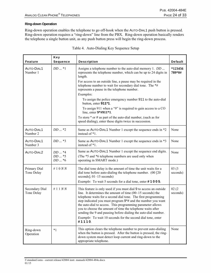
Ring-down Operation
Ring-down operation enables the telephone to go off-hook when the AUTO-DIAL1 push button is pressed. Ring-down operation requires a “ring-down” line from the PBX. Ring-down operation basically renders the telephone a single button unit, as any push button press will begin the ring-down process.
Table 4. Auto-Dialing Key Sequence Setup
Feature
Key Sequence
Description
Default
AUTO-DIAL1 Number 1
DD ... *1 Assigns a telephone number to the auto-dial memory 1. DD ... represents the telephone number, which can be up to 24 digits in length.
For access to an outside line, a pause may be required in the telephone number to wait for secondary dial tone. The *# represents a pause in the telephone number.
Examples:
To assign the police emergency number 911 to the auto-dial button, enter 911*1.
To assign 911 when a “9” is required to gain access to a CO line, enter 9*#911*1.
To store * or # as part of the auto-dial number, (such as for speed dialing), enter these digits twice in succession.
*123456789*0#
AUTO-DIAL1 Number 2
DD ... *2 Same as AUTO-DIAL1 Number 1 except the sequence ends in *2 instead of *1.
None
AUTO-DIAL1 Number 3
DD ... *3 Same as AUTO-DIAL1 Number 1 except the sequence ends in *3 instead of *1.
None
AUTO-DIAL2 DD ... *4 DD ... *5 DD ... *6
Same as AUTO-DIAL1 Number 1 except the sequence end digits.
(The *5 and *6 telephone numbers are used only when operating in SMART mode.)
None
Primary Dial Tone Delay
# 1 0 N N The dial tone delay is the amount of time the unit waits for a dial tone before auto-dialing the telephone number. (00 [20 seconds]; 01–15 seconds)
Example: To wait 5 seconds for a dial tone, enter # 1 0 0 5.
03 (3 seconds)
Secondary Dial Tone Delay
# 1 1 N N This feature is only used if you must dial 9 to access an outside line. It determines the amount of time (00–15 seconds) the telephone waits for a second dial tone. The first programming step indicated you must program 9*# and the number you want the auto-dial to access. This programming parameter allows you to choose the amount of time the telephone waits after sending the 9 and pausing before dialing the auto-dial number.
Example: To wait 10 seconds for the second dial tone, enter # 1 1 1 0.
02 (2 seconds)
Ring-down Operation
*1 This option clears the telephone number to prevent auto-dialing when the button is pressed. After the button is pressed, the ring-down system must detect loop current and ring-down to the appropriate telephone.
None
PUB. 42004-484E
ANALOG CLEAN PHONE®
TELEPHONES PAGE 25 of 33
f:\standard ioms - current release\42004 instr. manuals\42004-484e.docx 01/15
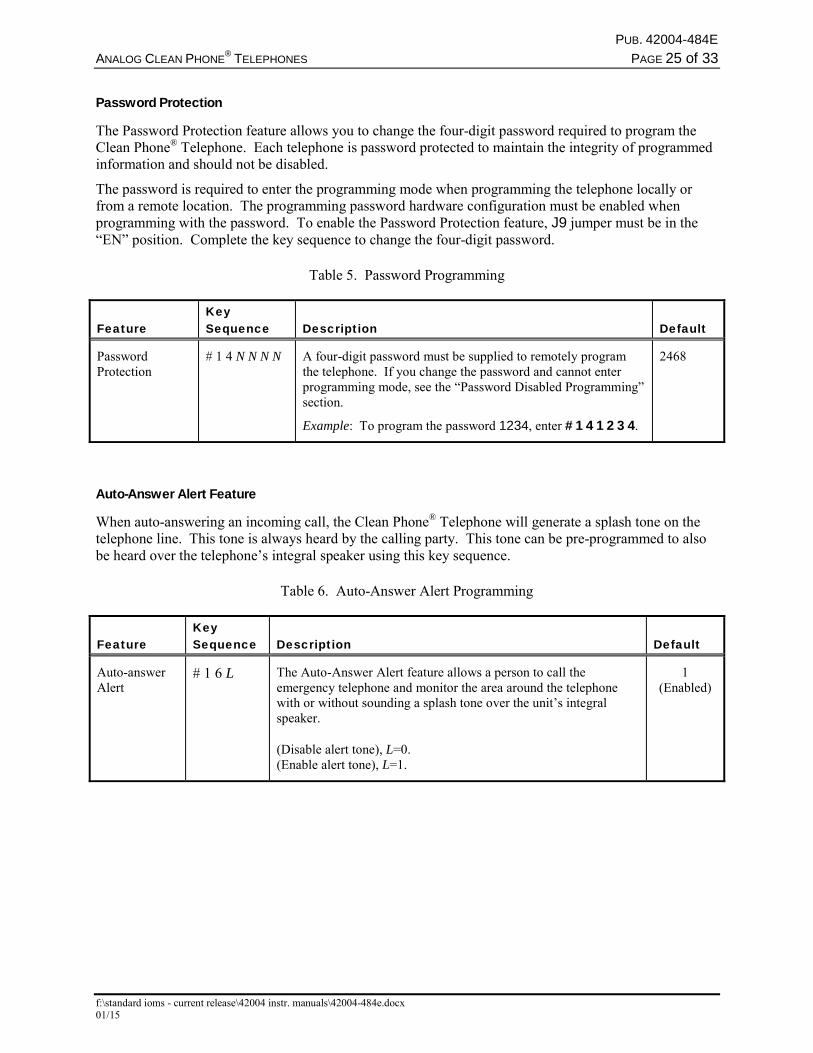
Password Protection
The Password Protection feature allows you to change the four-digit password required to program the Clean Phone® Telephone. Each telephone is password protected to maintain the integrity of programmed information and should not be disabled.
The password is required to enter the programming mode when programming the telephone locally or from a remote location. The programming password hardware configuration must be enabled when programming with the password. To enable the Password Protection feature, J9 jumper must be in the “EN” position. Complete the key sequence to change the four-digit password.
Table 5. Password Programming
Feature
Key Sequence
Description
Default
Password Protection
# 1 4 N N N N A four-digit password must be supplied to remotely program the telephone. If you change the password and cannot enter programming mode, see the “Password Disabled Programming” section.
Example: To program the password 1234, enter # 1 4 1 2 3 4.
2468
Auto-Answer Alert Feature
When auto-answering an incoming call, the Clean Phone® Telephone will generate a splash tone on the telephone line. This tone is always heard by the calling party. This tone can be pre-programmed to also be heard over the telephone’s integral speaker using this key sequence.
Table 6. Auto-Answer Alert Programming
Feature
Key Sequence
Description
Default
Auto-answer Alert
# 1 6 L The Auto-Answer Alert feature allows a person to call the emergency telephone and monitor the area around the telephone with or without sounding a splash tone over the unit’s integral speaker.
(Disable alert tone), L=0. (Enable alert tone), L=1.
1 (Enabled)
PUB. 42004-484E
ANALOG CLEAN PHONE®
TELEPHONES PAGE 26 of 33
f:\standard ioms - current release\42004 instr. manuals\42004-484e.docx 01/15
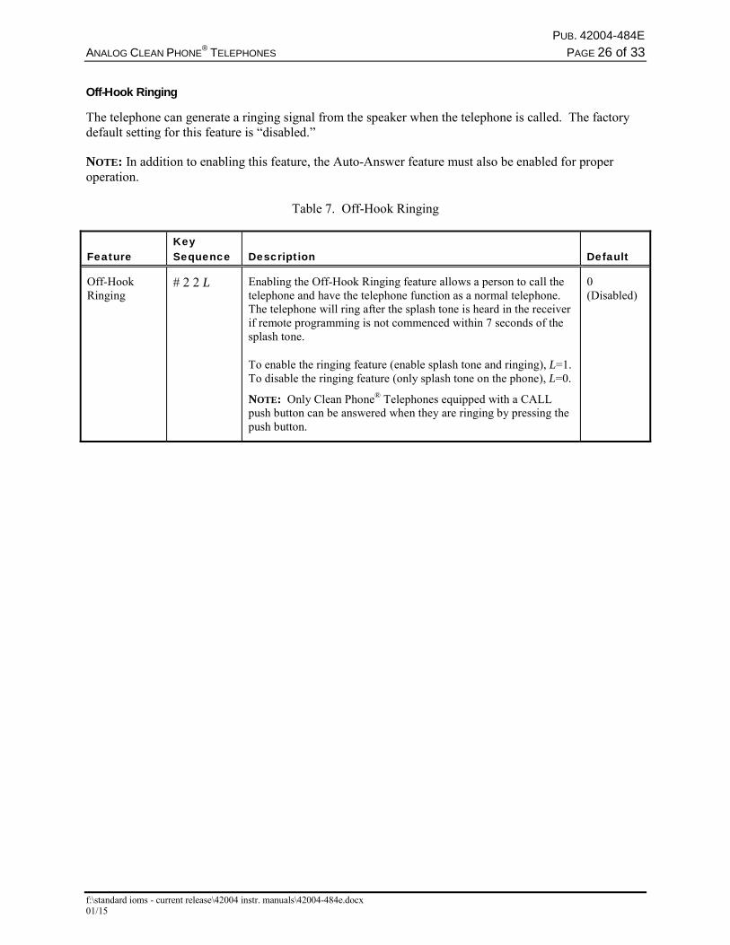
Off-Hook Ringing
The telephone can generate a ringing signal from the speaker when the telephone is called. The factory default setting for this feature is “disabled.”
NOTE: In addition to enabling this feature, the Auto-Answer feature must also be enabled for proper operation.
Table 7. Off-Hook Ringing
Feature
Key Sequence
Description
Default
Off-Hook Ringing
# 2 2 L Enabling the Off-Hook Ringing feature allows a person to call the telephone and have the telephone function as a normal telephone. The telephone will ring after the splash tone is heard in the receiver if remote programming is not commenced within 7 seconds of the splash tone.
To enable the ringing feature (enable splash tone and ringing), L=1. To disable the ringing feature (only splash tone on the phone), L=0.
NOTE: Only Clean Phone® Telephones equipped with a CALL push button can be answered when they are ringing by pressing the push button.
0 (Disabled)
PUB. 42004-484E
ANALOG CLEAN PHONE®
TELEPHONES PAGE 27 of 33
f:\standard ioms - current release\42004 instr. manuals\42004-484e.docx 01/15
Disconnect Options
Several options are available for disconnecting a call. Any combination of disconnect options may be used. Select the method that best suits the application, and follow the appropriate programming directions.
Table 8. Disconnect Options
Feature
Key Sequence
Description
Default
Call Time-out Disconnect Option
# 1 2 N N This feature programs the maximum length of a call if no other disconnect features are used. The valid entries are 1–99, representing 1-minute increments and 0 representing 4.5 hours. The call duration timer begins when the telephone goes off-hook. The telephone automatically disconnects after the programmed time-out period elapses.
Example: To make the maximum call length 2 minutes, enter # 1 2 0 2.
10 (10 minutes)
Dial Tone Disconnect Option
# 1 9 L NOTE: Use this option only if no other disconnect options are available.
If this option is enabled, the telephone automatically terminates a call if it detects a dial tone continuously for 10 seconds, such as if the called party hangs up. To enable the dial tone disconnect, L=1. To disable the dial tone disconnect, L = 0.
Example: To enable the dial tone disconnect, enter # 1 9 1. To disable the dial tone disconnect, enter # 1 9 0.
0 (Disabled)
NOTE: Simply pressing the on/off push button will disconnect the call.
Extended Control Output Operation
Output 1 can be programmed for extended operation (remain closed) for up to 255 minutes (in 1-minute increments) after the emergency call ends.
Table 9. Extended Strobe Operation
Feature
Key Sequence
Description
Default
Extended Strobe Operation
# 2 5 N N N Sets the duration of the activation of the Output 1 contact starting at the end of a call. Use entries 001–255, representing 1 minute to 255 minutes in 1-minute increments. Use 000 to disable this feature. To set a duration of 7 minutes, enter # 2 5 0 0 7.
0 0 0 (Disabled)
PUB. 42004-484E
ANALOG CLEAN PHONE®
TELEPHONES PAGE 28 of 33
f:\standard ioms - current release\42004 instr. manuals\42004-484e.docx 01/15
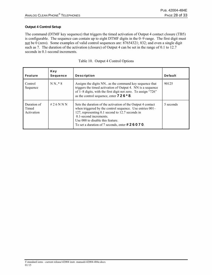
Output 4 Control Setup
The command (DTMF key sequence) that triggers the timed activation of Output 4 contact closure (TB5) is configurable. The sequence can contain up to eight DTMF digits in the 0–9 range. The first digit must not be 0 (zero). Some examples of valid control sequences are: 87654321; 832; and even a single digit such as 7. The duration of the activation (closure) of Output 4 can be set in the range of 0.1 to 12.7 seconds in 0.1-second increments.
Table 10. Output 4 Control Options
Feature
Key Sequence
Description
Default
Control Sequence
N N..* 8 Assigns the digits NN.. as the command key sequence that triggers the timed activation of Output 4. NN is a sequence of 1–8 digits, with the first digit not zero. To assign “726” as the control sequence, enter 7 2 6 * 8.
90125
Duration of Timed Activation
# 2 6 N N N Sets the duration of the activation of the Output 4 contact when triggered by the control sequence. Use entries 001–127, representing 0.1 second to 12.7 seconds in 0.1-second increments. Use 000 to disable this feature. To set a duration of 7 seconds, enter # 2 6 0 7 0.
5 seconds
PUB. 42004-484E
ANALOG CLEAN PHONE®
TELEPHONES PAGE 29 of 33
f:\standard ioms - current release\42004 instr. manuals\42004-484e.docx 01/15
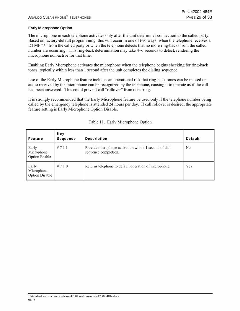
Early Microphone Option
The microphone in each telephone activates only after the unit determines connection to the called party. Based on factory-default programming, this will occur in one of two ways; when the telephone receives a DTMF “*” from the called party or when the telephone detects that no more ring-backs from the called number are occurring. This ring-back determination may take 4–6 seconds to detect, rendering the microphone non-active for that time.
Enabling Early Microphone activates the microphone when the telephone begins checking for ring-back tones, typically within less than 1 second after the unit completes the dialing sequence.
Use of the Early Microphone feature includes an operational risk that ring-back tones can be missed or audio received by the microphone can be recognized by the telephone, causing it to operate as if the call had been answered. This could prevent call “rollover” from occurring.
It is strongly recommended that the Early Microphone feature be used only if the telephone number being called by the emergency telephone is attended 24 hours per day. If call rollover is desired, the appropriate feature setting is Early Microphone Option Disable.
Table 11. Early Microphone Option
Feature Key Sequence Description Default
Early Microphone Option Enable
# 7 1 1 Provide microphone activation within 1 second of dial sequence completion.
No
Early Microphone Option Disable
# 7 1 0 Returns telephone to default operation of microphone. Yes
PUB. 42004-484E
ANALOG CLEAN PHONE®
TELEPHONES PAGE 30 of 33
f:\standard ioms - current release\42004 instr. manuals\42004-484e.docx 01/15
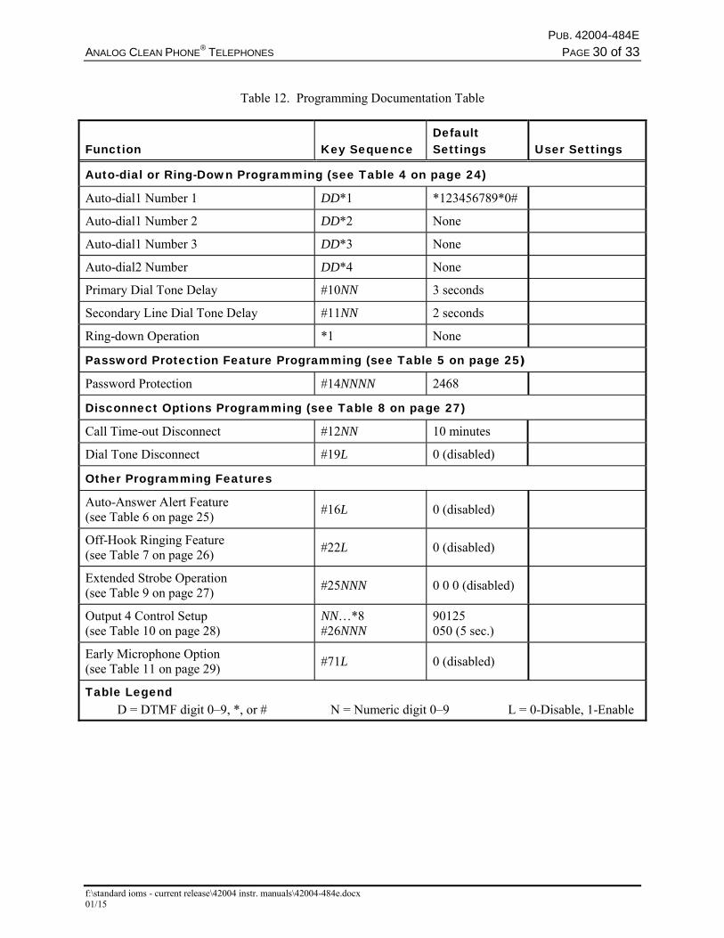
Table 12. Programming Documentation Table
Function Key Sequence Default Settings User Settings
Auto-dial or Ring-Down Programming (see Table 4 on page 24)
Auto-dial1 Number 1 DD*1 *123456789*0#
Auto-dial1 Number 2 DD*2 None
Auto-dial1 Number 3 DD*3 None
Auto-dial2 Number DD*4 None
Primary Dial Tone Delay #10NN 3 seconds
Secondary Line Dial Tone Delay #11NN 2 seconds
Ring-down Operation *1 None
Password Protection Feature Programming (see Table 5 on page 25)
Password Protection #14NNNN 2468
Disconnect Options Programming (see Table 8 on page 27)
Call Time-out Disconnect #12NN 10 minutes
Dial Tone Disconnect #19L 0 (disabled)
Other Programming Features
Auto-Answer Alert Feature (see Table 6 on page 25)
#16L 0 (disabled)
Off-Hook Ringing Feature (see Table 7 on page 26)
#22L 0 (disabled)
Extended Strobe Operation (see Table 9 on page 27)
#25NNN 0 0 0 (disabled)
Output 4 Control Setup (see Table 10 on page 28)
NN…*8 #26NNN
90125 050 (5 sec.)
Early Microphone Option (see Table 11 on page 29)
#71L 0 (disabled)
Table Legend D = DTMF digit 0–9, *, or # N = Numeric digit 0–9 L = 0-Disable, 1-Enable
PUB. 42004-484E
ANALOG CLEAN PHONE®
TELEPHONES PAGE 31 of 33
f:\standard ioms - current release\42004 instr. manuals\42004-484e.docx 01/15
SMART Mode Programming TMA Software is designed to remotely program Clean Phone® Telephones for SMART mode operation. Although they can be locally programmed for SMART operation, there is no advantage to having a Clean Phone® Telephone set up for SMART mode without having TMA installed.
Clean Phone® Telephones installed in systems that will have TMA operational at a later date are recommended to be programmed for Standard Mode operation. Upon installation of TMA, the installed telephones can be reprogrammed from the TMA PC.
Maintenance
WARNING This product can contain hazardous voltages. Always remove power to this station prior to servicing.
General Information 1. Inspect and replace frayed or cracked wiring.
2. Secure/replace loose wires and terminal lugs.
3. Remove corrosion from terminals.
Service If your Clean Phone® Telephone requires depot service, contact your Regional Service Center for a return authorization number (RA#). Equipment should be shipped prepaid to GAI-Tronics with a return authorization number and a purchase order number. If the equipment is under warranty, repairs will be made without charge. Please include a written explanation of all defects to assist our technicians in their troubleshooting efforts.
Call 800-492-1212 inside the USA or 610-777-1374 outside the USA for help identifying the Regional Service Center closest to you.
PUB. 42004-484E
ANALOG CLEAN PHONE®
TELEPHONES PAGE 32 of 33
f:\standard ioms - current release\42004 instr. manuals\42004-484e.docx 01/15
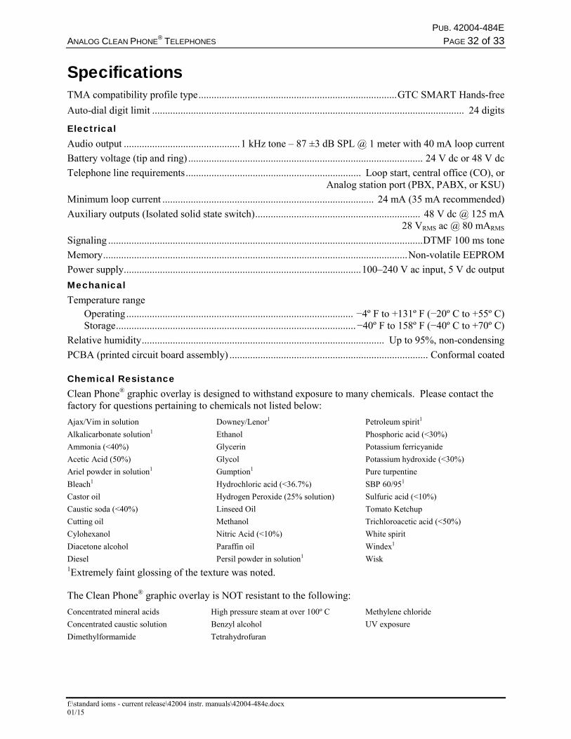
Specifications TMA compatibility profile type ............................................................................. GTC SMART Hands-free
Auto-dial digit limit ......................................................................................................................... 24 digits
Electrical Audio output ............................................. 1 kHz tone – 87 ±3 dB SPL @ 1 meter with 40 mA loop current
Battery voltage (tip and ring) ........................................................................................... 24 V dc or 48 V dc
Telephone line requirements .................................................................... Loop start, central office (CO), or Analog station port (PBX, PABX, or KSU)
Minimum loop current .................................................................................. 24 mA (35 mA recommended)
Auxiliary outputs (Isolated solid state switch) ................................................................ 48 V dc @ 125 mA 28 VRMS ac @ 80 mARMS
Signaling .......................................................................................................................... DTMF 100 ms tone
Memory ...................................................................................................................... Non-volatile EEPROM
Power supply ............................................................................................ 100–240 V ac input, 5 V dc output
Mechanical Temperature range Operating ........................................................................................ −4º F to +131º F (−20º C to +55º C) Storage ............................................................................................. −40º F to 158º F (−40º C to +70º C)
Relative humidity .............................................................................................. Up to 95%, non-condensing
PCBA (printed circuit board assembly) ............................................................................. Conformal coated
Chemical Resistance Clean Phone® graphic overlay is designed to withstand exposure to many chemicals. Please contact the factory for questions pertaining to chemicals not listed below:
Ajax/Vim in solution Downey/Lenor1 Petroleum spirit1
Alkalicarbonate solution1 Ethanol Phosphoric acid (<30%)
Ammonia (<40%) Glycerin Potassium ferricyanide
Acetic Acid (50%) Glycol Potassium hydroxide (<30%)
Ariel powder in solution1 Gumption1 Pure turpentine
Bleach1 Hydrochloric acid (<36.7%) SBP 60/951
Castor oil Hydrogen Peroxide (25% solution) Sulfuric acid (<10%)
Caustic soda (<40%) Linseed Oil Tomato Ketchup
Cutting oil Methanol Trichloroacetic acid (<50%)
Cylohexanol Nitric Acid (<10%) White spirit
Diacetone alcohol Paraffin oil Windex1
Diesel Persil powder in solution1 Wisk 1Extremely faint glossing of the texture was noted.
The Clean Phone® graphic overlay is NOT resistant to the following:
Concentrated mineral acids High pressure steam at over 100º C Methylene chloride
Concentrated caustic solution Benzyl alcohol UV exposure
Dimethylformamide Tetrahydrofuran
PUB. 42004-484E
ANALOG CLEAN PHONE®
TELEPHONES PAGE 33 of 33
f:\standard ioms - current release\42004 instr. manuals\42004-484e.docx 01/15
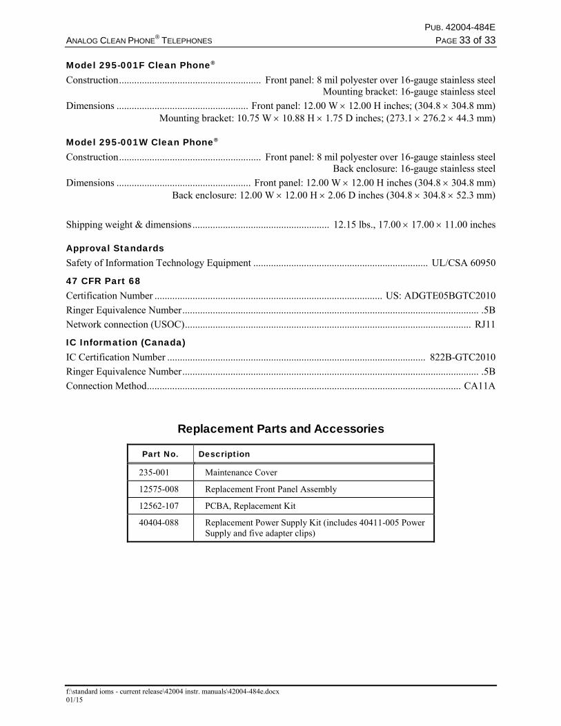
Model 295-001F Clean Phone® Construction ........................................................ Front panel: 8 mil polyester over 16-gauge stainless steel Mounting bracket: 16-gauge stainless steel
Dimensions .................................................... Front panel: 12.00 W 12.00 H inches; (304.8 304.8 mm) Mounting bracket: 10.75 W 10.88 H 1.75 D inches; (273.1 276.2 44.3 mm) Model 295-001W Clean Phone® Construction ........................................................ Front panel: 8 mil polyester over 16-gauge stainless steel Back enclosure: 16-gauge stainless steel
Dimensions ..................................................... Front panel: 12.00 W 12.00 H inches (304.8 304.8 mm) Back enclosure: 12.00 W 12.00 H 2.06 D inches (304.8 304.8 52.3 mm)
Shipping weight & dimensions ...................................................... 12.15 lbs., 17.00 17.00 11.00 inches
Approval Standards Safety of Information Technology Equipment ..................................................................... UL/CSA 60950
47 CFR Part 68 Certification Number .......................................................................................... US: ADGTE05BGTC2010
Ringer Equivalence Number ..................................................................................................................... .5B
Network connection (USOC) ................................................................................................................. RJ11
IC Information (Canada) IC Certification Number ...................................................................................................... 822B-GTC2010
Ringer Equivalence Number ..................................................................................................................... .5B
Connection Method ............................................................................................................................ CA11A
Replacement Parts and Accessories
Part No. Description
235-001 Maintenance Cover
12575-008 Replacement Front Panel Assembly
12562-107 PCBA, Replacement Kit
40404-088 Replacement Power Supply Kit (includes 40411-005 Power Supply and five adapter clips)
(Rev. 10/06)
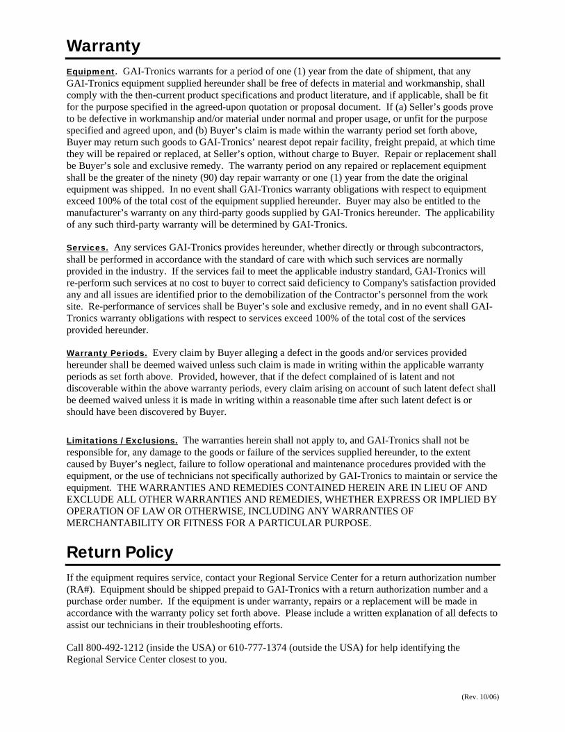
WarrantyEquipment. GAI-Tronics warrants for a period of one (1) year from the date of shipment, that anyGAI-Tronics equipment supplied hereunder shall be free of defects in material and workmanship, shallcomply with the then-current product specifications and product literature, and if applicable, shall be fitfor the purpose specified in the agreed-upon quotation or proposal document. If (a) Seller’s goods proveto be defective in workmanship and/or material under normal and proper usage, or unfit for the purposespecified and agreed upon, and (b) Buyer’s claim is made within the warranty period set forth above,Buyer may return such goods to GAI-Tronics’ nearest depot repair facility, freight prepaid, at which timethey will be repaired or replaced, at Seller’s option, without charge to Buyer. Repair or replacement shallbe Buyer’s sole and exclusive remedy. The warranty period on any repaired or replacement equipmentshall be the greater of the ninety (90) day repair warranty or one (1) year from the date the originalequipment was shipped. In no event shall GAI-Tronics warranty obligations with respect to equipmentexceed 100% of the total cost of the equipment supplied hereunder. Buyer may also be entitled to themanufacturer’s warranty on any third-party goods supplied by GAI-Tronics hereunder. The applicabilityof any such third-party warranty will be determined by GAI-Tronics.
Services. Any services GAI-Tronics provides hereunder, whether directly or through subcontractors,shall be performed in accordance with the standard of care with which such services are normallyprovided in the industry. If the services fail to meet the applicable industry standard, GAI-Tronics willre-perform such services at no cost to buyer to correct said deficiency to Company's satisfaction providedany and all issues are identified prior to the demobilization of the Contractor’s personnel from the worksite. Re-performance of services shall be Buyer’s sole and exclusive remedy, and in no event shall GAI-Tronics warranty obligations with respect to services exceed 100% of the total cost of the servicesprovided hereunder.
Warranty Periods. Every claim by Buyer alleging a defect in the goods and/or services providedhereunder shall be deemed waived unless such claim is made in writing within the applicable warrantyperiods as set forth above. Provided, however, that if the defect complained of is latent and notdiscoverable within the above warranty periods, every claim arising on account of such latent defect shallbe deemed waived unless it is made in writing within a reasonable time after such latent defect is orshould have been discovered by Buyer.
Limitations / Exclusions. The warranties herein shall not apply to, and GAI-Tronics shall not beresponsible for, any damage to the goods or failure of the services supplied hereunder, to the extentcaused by Buyer’s neglect, failure to follow operational and maintenance procedures provided with theequipment, or the use of technicians not specifically authorized by GAI-Tronics to maintain or service theequipment. THE WARRANTIES AND REMEDIES CONTAINED HEREIN ARE IN LIEU OF ANDEXCLUDE ALL OTHER WARRANTIES AND REMEDIES, WHETHER EXPRESS OR IMPLIED BYOPERATION OF LAW OR OTHERWISE, INCLUDING ANY WARRANTIES OFMERCHANTABILITY OR FITNESS FOR A PARTICULAR PURPOSE.
Return PolicyIf the equipment requires service, contact your Regional Service Center for a return authorization number(RA#). Equipment should be shipped prepaid to GAI-Tronics with a return authorization number and apurchase order number. If the equipment is under warranty, repairs or a replacement will be made inaccordance with the warranty policy set forth above. Please include a written explanation of all defects toassist our technicians in their troubleshooting efforts.
Call 800-492-1212 (inside the USA) or 610-777-1374 (outside the USA) for help identifying theRegional Service Center closest to you.


![Quick Guide - audiocodes.com · Cet appareil numérique de la classe [B] ... Analog telephones ... Idle Proxy register failed - Off](https://img.dokumen.tips/doc/110x75/5bdc164d09d3f2bc1c8d36df/quick-guide-cet-appareil-numerique-de-la-classe-b-analog-telephones.jpg)