Embed Size (px)
Citation preview

AN822: Intel® FPGA ConfigurationDevice Migration Guideline
SubscribeSend Feedback
AN-822 | 2018.03.30Latest document on the web: PDF | HTML

Contents
1 Intel® FPGA Configuration Device Migration Guideline.....................................................31.1 Migration Considerations..........................................................................................31.2 Software Migration Guidelines.................................................................................. 5
1.2.1 IP Core Compatibility.................................................................................. 51.2.2 Programming File Compatibility.................................................................... 61.2.3 IP Core and Programming File Migration Guideline...........................................71.2.4 Software Support for EPCQ-A Devices............................................................9
1.3 Specification Comparison.........................................................................................91.3.1 Operating Conditions.................................................................................101.3.2 Timing Specifications.................................................................................101.3.3 Operation Codes....................................................................................... 131.3.4 Pin Information.........................................................................................151.3.5 Package Dimensions..................................................................................171.3.6 Status Register.........................................................................................20
1.4 Evaluating Data Setup and Hold Timing Slack........................................................... 231.5 Document Revision History for AN 822: Intel FPGA Configuration Device Migration
Guideline......................................................................................................... 25
Contents
AN822: Intel® FPGA Configuration Device Migration Guideline2

1 Intel® FPGA Configuration Device Migration GuidelineThis document describes the guidelines for migrating from the Serial Configuration(EPCS) and Quad-Serial Configuration (EPCQ) devices to the Quad-Serial Configuration(EPCQ-A) devices.
Related Links
• Serial Configuration (EPCS) Devices Datasheet
• Quad-Serial Configuration (EPCQ) Devices Datasheet
• Quad-Serial Configuration (EPCQ-A) Devices Datasheet
1.1 Migration Considerations
The EPCQ-A devices are conditionally compatible for a direct migration from EPCQ andEPCS devices.
You must consider the following items to determine the compatibility and the nextstep of action for a successful device migration.
IP Cores
If you are using Intel® IP cores, you may need to regenerate and recompile yourdesign. In certain conditions, the programming files can be reused withoutrecompilation. Refer to IP Core Compatibility on page 5 for more information aboutIP core compatibility. Refer to Table 3 on page 6 if you are not using IP cores thatinterface with the configuration device.
Pins, Package and Capacity
Migration can only be done to an EPCQ-A device that has sufficient capacity for theprogramming file and have the same pin count package.
Pin 3 (nRESET) on the EPCQ64A and EPCQ128A devices act as a reset pin. This pinhas an internal pull-up, and if you do not use the reset function, connect the nRESETpin to either VCC or leave it unconnected. Refer to Pin Information on page 15 formore information about the pin-outs and descriptions.
AN-822 | 2018.03.30
Intel Corporation. All rights reserved. Intel, the Intel logo, Altera, Arria, Cyclone, Enpirion, MAX, Nios, Quartusand Stratix words and logos are trademarks of Intel Corporation or its subsidiaries in the U.S. and/or othercountries. Intel warrants performance of its FPGA and semiconductor products to current specifications inaccordance with Intel's standard warranty, but reserves the right to make changes to any products and servicesat any time without notice. Intel assumes no responsibility or liability arising out of the application or use of anyinformation, product, or service described herein except as expressly agreed to in writing by Intel. Intelcustomers are advised to obtain the latest version of device specifications before relying on any publishedinformation and before placing orders for products or services.*Other names and brands may be claimed as the property of others.
ISO9001:2008Registered

Figure 1. EPCS to EPCQ Migration Pin Package and Capacity Summary
EPCQ128
EPCQ64
EPCQ32
EPCQ16
EPCS128
EPCS64
EPCS16
EPCS4
EPCS1
EPCQ16A EPCQ32A EPCQ64A EPCQ128AEPCQ4A1
FromEPCS
FromEPCQ
Yes Yes
Yes Yes
YesNo Yes
Yes
YesYes2
1.2.
EPCQ4A devices support Active Serial x1 configuration only.Note:
Yes2
Yes2
Yes2
Yes No No
Yes No No
Yes No No
No No No
No No
Variant
To EPCQ-A
No Yes
No
Yes
No
No
No
Yes No No
Yes No No
No Yes Yes
No No
Migration is compatible only if the destination EPCQ-A device hasthe sufficient capacity for the programming file.
Operation Commands
The dummy clock requirement of the fast read (0Bh) and extended quad input fastread (EBh) commands:
• EPCQ—the dummy clock is configurable with the non-volatile configuration register(NVCR). When the EPCQ is used with a Cyclone® V, Arria® V or Stratix® V device,the dummy clock is configured to be 4, 10 or 12, depending on the byte-addressing mode and ASx1 or ASx4 configuration. However, in EPCQ-A devices,the dummy clock is fixed at 8 and 6 for fast read and extended quad input fastread respectively. Therefore you must regenerate the programming files, suchas .pof, .jic, and .rpd.
• EPCS—the dummy clock is fixed at 8 for fast read, therefore you do not have toregenerate the programming files if all other conditions are met. Table 3 on page6 defines the need to regenerate the programming files. Refer to IP Core andProgramming File Migration Guideline on page 7 for more information about theconditions.
Status Register
Status Register contains the Top/Bottom (TB) bit (bit 5), Block Protect (BP) bits (bit 4,bit 3, bit 2) for sector protection bits. EPCS devices do not have TP bit and some EPCQdevice densities have BP3 (bit 6), while bit 6 is reserved in EPCQ-A devices. Due tothis differences, you may need to recompile the programming file if your design usesthe sector protect feature. Refer to Status Register on page 20 for more informationabout status registers and sector protect bits.
1 Intel® FPGA Configuration Device Migration Guideline
AN-822 | 2018.03.30
AN822: Intel® FPGA Configuration Device Migration Guideline4

Sector Size
All of the EPCS, EPCQ and EPCQ-A devices have the sector size of 512kb except forEPCS128 which has 2Mb. This impacts the sector erase operation. If the design iserasing the flash during user mode, you must update your design to comply the sectorsize when migrating from EPCS128 to EPCQ128A. After updating your design,regenerate a new programming file for the EPCQ-A device.
1.2 Software Migration Guidelines
1.2.1 IP Core Compatibility
Table 1. EPCS to EPCQ-A Device Migration IP Core Compatibility
IP Core Compatibility Condition
ASMI Parallel Yes/No • If sector protect is used, refer to Sector Protect on page 20 todetermine compatibility.
• EPCS128 has different sector size than EPCQ128A, notcompatible if sector erase is used.
Serial Flash Controller Yes/No
Serial Flash Loader (SFL) Yes/No • Compatible for Cyclone V, Arria V and Stratix V devices.• For devices earlier than Cyclone V, Arria V and Stratix V, it is
compatible if the Enhanced SFL(1) is enabled.
Remote Update Yes
Table 2. EPCQ to EPCQ-A Device Migration IP Core Compatibility
IP Core Compatibility Condition
ASMI Parallel Yes/No • If sector protect is used, refer to sector protect tablecomparison to determine compatibility.
• Not compatible if read dummy clock is enabled.
ASMI Parallel II No —
Serial Flash Controller No —
Serial Flash Controller II No —
Generic QSPI Controller No —
Generic QSPI ControllerII
No —
Serial Flash Loader Yes/No • Compatible for Cyclone V, Arria V and Stratix V devices.• For devices earlier than Cyclone V, Arria V and Stratix V, it is
compatible if the Enhanced SFL(1) is enabled.
Remote Update Yes —
Related Links
• Altera Remote Update IP Core User Guide
• Altera ASMI Parallel IP Core User Guide
• Converting .sof to .jic Files in the Quartus Prime Software
(1) Enhanced SFL is an option available in the Serial Flash Loader IP core when using with devicesearlier than Cyclone V, Arria V and Stratix V.
1 Intel® FPGA Configuration Device Migration Guideline
AN-822 | 2018.03.30
AN822: Intel® FPGA Configuration Device Migration Guideline5

• Programming Serial Configuration Devices Using the Quartus Prime Programmerand .jic Files
1.2.2 Programming File Compatibility
Note: This section describes programming file compatibility for designs without Intel FPGA IPcores.
List of supported programming files:
• Programmer Object File (.pof)
• JTAG Indirect Configuration File (.jic)
• Raw Programming Data (.rpd)
• STAPL File (.jam/.jbc)
• Serial Vector Format (.svf)
Table 3. Programming File Compatibility Guide
Note: For designs that do not contain IP cores which interface with the configuration device,depending upon the FPGA family and configuration scheme implemented, the existingprogramming files may be compatible with EPCQ-A devices without the need to regeneratethe programming files.
Device Family OriginalConfiguration
Device
ConfigurationDevice Density
Programming Files supported DisableEPCS/
EPCQ IDcheck
Setting
Compatiblewith EPCQ-
A(2)(3)
Legacy FPGAdevices
EPCS 64Mb & below .pof/.jic/.rpd/.jam/.jbc Any Yes
.svf Any Yes(4)
128Mb .pof/.jic/.rpd Any Yes(5)
.svf Any Yes(4)
.jam/.jbc Any No(6)
EPCQ Any .pof/.jic/.rpd/.jam/.jbc On(7) Yes
continued...
(2) Table assumes other compatibility considerations are satisfied.
(3) Table assumes the programming files do not contain any ASMI Parallel IP or Serial FlashLoader IP.
(4) Only supported for .svf files generated for EPCS devices to be used to program an EPCQ-A,and not the other way round.
(5) In .rpd file, the binary data is the same between EPCS128 and EPCQ128A. However due todifferent sector size, a proper erasing procedure is required when programming each device.
(6) Due to different sector size, the .jam/.jbc file is different between EPCS and EPCQ.
(7) In Intel Quartus® Prime version 15.1 or later, automatic mode turns on this optionautomatically.
1 Intel® FPGA Configuration Device Migration Guideline
AN-822 | 2018.03.30
AN822: Intel® FPGA Configuration Device Migration Guideline6

Device Family OriginalConfiguration
Device
ConfigurationDevice Density
Programming Files supported DisableEPCS/
EPCQ IDcheck
Setting
Compatiblewith EPCQ-
A(2)(3)
.svf On(7) Yes(4)
Cyclone V, Arria V,and Stratix Vdevices
EPCS 64Mb & below .pof/.jic/.rpd/.jam/.jbc On(8) Yes
.svf On(8) Yes(4)
128Mb .pof/.jic/.rpd On(8) Yes(5)
.svf On(8) Yes(4)
.jam/.jbc Any No(6)
EPCQ(9) Any Any Any No
Refer to IP Core and Programming File Migration Guideline on page 7 for moreinformation about guidelines on incompatible programming files.
1.2.3 IP Core and Programming File Migration Guideline
Note: This section describes programming file compatibility for designs with Intel FPGA IPcores that interface with the configuration device.
Refer to the following diagram to determine the subsequent tasks and guidelines formigration:
• IP core and programming file are incompatible—regenerate IP core andprogramming file shown in IP Core Regeneration Guideline on page 8.
• Programming file is incompatible—regenerate programming file shown in Programming File Regeneration Guideline on page 9.
• IP core and programming file are compatible—no additional task required and youcan reuse the existing programming file.
(2) Table assumes other compatibility considerations are satisfied.
(3) Table assumes the programming files do not contain any ASMI Parallel IP or Serial FlashLoader IP.
(8) Other than Intel Quartus Prime version 13.0 to 15.0, automatic mode turns on this optionautomatically.
(9) EPCQ programming files are not compatible with EPCQ-A in AS x1 or AS x4 modes.
1 Intel® FPGA Configuration Device Migration Guideline
AN-822 | 2018.03.30
AN822: Intel® FPGA Configuration Device Migration Guideline7

Figure 2. IP Core and Programming File Compatibility Flow Chart
EPCQEPCS
Start
IP core iscompatible?1
Cyclone V, Arria V orStratix V?
EPCS128 && useerase sector?
Use .svf file?
Size<=32Mb &&SR2[6:5]=2b’00?
EPCS64 &&SR2[6]=1b’0?
Use sector protect?
Notes:1. Check IP core compatibility in IP Core Compatibility section.2. SR is status register.3. IP core and programming file can be migrated without regeneration.
Disable ID check onprogramming file?
No
No
No
No
No
No
No
No
Yes
Yes
Yes
Yes
Yes
Yes
Yes
Regenerate IP core andprogramming file
Regenerate IP core andprogramming file Regenerate
programming file
Programming fileis compatible3
1.2.3.1 IP Core Regeneration Guideline
To regenerate the IP core and programming file with the correct settings, perform thefollowing steps:
1. Regenerate the desired IP cores.
a. If you use the sector protect feature:
1 Intel® FPGA Configuration Device Migration Guideline
AN-822 | 2018.03.30
AN822: Intel® FPGA Configuration Device Migration Guideline8

• For EPCQ4A, EPCQ16A, and EPCQ32A—ensure the status register bit [6:5]is set to 0.
• For EPCQ64A—ensure the status register bit [6] is set to 0.
b. For EPCS128 to EPCQ128A migration—sector erase must comply to the sectorsize of EPCQ128A.
Note: Sector size for EPCS128 and EPCQ128A are 2Mb and 512kb respectively.
2. Recompile the configuration bitstream to obtain the .sof file.
1.2.3.2 Programming File Regeneration Guideline
To regenerate the programming file with the correct settings, perform the followingsteps:
1. Convert the .sof file to the desired programming file in the Intel Quartus PrimeConvert Programing File tool and ensure that you:
• Select the correct EPCQ-A device you are migrating to.
• Enable the Disable EPCS/EPCQ ID check option. This option is available inthe Advanced Option settings of the Convert Programming File tool in IntelQuartus Prime software.
• For migration from EPCS devices—Select AS x1 configuration mode.
2. Program the programming file into EPCQ-A device using Intel Quartus PrimeProgrammer.
1.2.4 Software Support for EPCQ-A Devices
Table 4. Intel Quartus Prime Software Support for EPCQ-A Devices
Intel Quartus Prime IP Cores Programmer and Programming FileGeneration
Intel Quartus Prime Pro Edition 17.1 No Yes
Intel Quartus Prime Standard Edition17.1
Yes Yes
1.3 Specification Comparison
The following tables show the side-by-side comparison of the EPCS, EPCQ and EPCQ-Aoperating conditions. For more detailed and up-to-date information, refer to therespective device datasheet.
1 Intel® FPGA Configuration Device Migration Guideline
AN-822 | 2018.03.30
AN822: Intel® FPGA Configuration Device Migration Guideline9

1.3.1 Operating Conditions
Table 5. EPCS, EPCQ and EPCQ-A Devices Operating Conditions
Parameter Condition Symbol Min Max Unit
EPCS EPCQ EPCQ-A EPCS EPCQ EPCQ-A
Supplyvoltage
The maximumVCC rise time is100 ms.
VCC 2.7 3.6 V
Operatingtemperature
For industrialuse
TA -40 85 °C
High-levelinput voltage
— VIH 0.6 xVCC
0.7 x VCC(10) VCC + 0.4 V
Low-levelinput voltage
— VIL -0.5 0.3 x VCC V
High-leveloutputvoltage
IOH =-100µA VOH VCC - 0.2 — V
Low-leveloutputvoltage
IOL =100µA VOL — 0.2 or 0.4(11) V
1.3.2 Timing Specifications
The following tables show the general comparison of the EPCS, EPCQ, and EPCQ-Aoperation timing. For more detailed and up-to-date information, refer to the respectivedevice datasheet.
Caution: You need to take note of these values to avoid from the migration to fail:
• t DH
• t DSU
• t nCLK2D/tCLQV
• tCLQX(12)
(10) The FPGA 2.5V I/O VOH level is insufficient to achieve EPCQ or EPCQ-A VIH threshold acrossentire voltage range.
(11) 0.2 V for EPCQ16A, EPCQ32A, EPCQ64A, and EPCQ128A. 0.4 V is for EPCQ4A
(12) Refer to Evaluating Data Setup and Hold Timing Slack on page 23 evaluate the data setup andhold timing slack.
1 Intel® FPGA Configuration Device Migration Guideline
AN-822 | 2018.03.30
AN822: Intel® FPGA Configuration Device Migration Guideline10

1.3.2.1 Read Operation Timing
Table 6. EPCS and EPCQ-A Devices Read Operation Timing Parameters
Symbol Parameter Capacity Min Max Unit
EPCS EPCQ-A EPCS EPCQ-A
f RCLK Read clock frequency All — — 20 50 MHz
Fast read clock frequency All — — 40 100 MHz
t CH DCLK high time 4 Mb 11 4 or 6(13) — — ns
All others 11 3.4 or9(14)
— —
t CL DCLK low time 4Mb 11 4 or 6(13) — — ns
All others 11 3.4 or9(14)
— —
t ODIS Output disable time after read All — — 8 7 ns
t nCLK2D /tCLQV
(15)Clock falling edge to DATA 4Mb — — 8 8 ns
All others — — 8 6
Table 7. EPCQ and EPCQ-A Devices Read Operation Timing Parameters
Symbol Parameter Capacity Min Max Unit
EPCQ EPCQ-A EPCQ EPCQ-A
f RCLK Read clock frequency All — — 50 50 MHz
Fast read clock frequency All — — 100 100 MHz
t CH DCLK high time All 4 3.4 or9(14)
— — ns
t CL DCLK low time All 4 3.4 or9(14)
— — ns
t ODIS Output disable time after read All — — 8 7 ns
t nCLK2D /tCLQV
(15)Clock falling edge to DATA All — — 7 6 ns
1.3.2.2 Write Operation Timing
Table 8. EPCS and EPCQ-A Devices Write Operation Timing Parameters
Symbol Operation Capacity Min Typical Max Unit
EPCS EPCQ-A EPCS EPCQ-A EPCS EPCQ-A
f WCLK Write clock frequency All — — 25 100 MHz
t CH DCLK high 4 20 4 — — ns
continued...
(13) 4 ns is for normal read and 6 ns is for fast read.
(14) 3.4 ns is for normal read and 9 ns is for fast read.
(15) t nCLK2D is used in EPCS and EPCQ devices while tCLQV is used in EPCQ-A devices.
1 Intel® FPGA Configuration Device Migration Guideline
AN-822 | 2018.03.30
AN822: Intel® FPGA Configuration Device Migration Guideline11

Symbol Operation Capacity Min Typical Max Unit
EPCS EPCQ-A EPCS EPCQ-A EPCS EPCQ-A
All others 20 3.4 — —
t CL DCLK low 4 20 4 — — ns
All others 20 4 — —
t NCSSU Chip select ( nCS ) setup All 10 5 — — ns
t NCSH Chip select ( nCS ) hold All 10 5 — — ns
t DSU DATA[] in setup beforeDCLK rising edge
All 5 2 — — ns
t DH DATA[] hold time afterDCLK rising edge
4 5 5 — — ns
All others 5 3 — —
t CSH Chip select ( nCS ) high 4 100 100 — — ns
All others 100 10 /50(16)
— —
t WB Write bytes cycle 1 — 1.5 — 5 — ms
4 — 1.5 0.4 5 0.8 ms
16 — 1.5 0.4 5 3 ms
32 — — 0.7 — 3 ms
64 — 1.5 0.8 5 3 ms
128 — 2.5 0.7 7 3 ms
t WS Write status cycle All — 5 10 15 15 ms
t EB Erase bulk cycle 1 — 3 — 6 — s
4 — 5 1 10 4 s
16 — 17 5 40 25 s
32 — — 10 — 50 s
64 — 68 20 160 100 s
128 — 105 40 250 200 s
t ES Erase sector cycle 4 — 2 0.15 3 1 s
All others — 2 0.15 3 2 s
Table 9. EPCQ and EPCQ-A Devices Write Operation Timing Parameters
Symbol Operation Capacity Min Typical Max Unit
EPCQ EPCQ-A EPCQ EPCQ-A EPCQ EPCQ-A
f WCLK Write clock frequency All — — 100 100 MHz
t CH DCLK high All 4 3.4 — — ns
t CL DCLK low All 4 4 — — ns
continued...
(16) 10ns for read and 50 ns for erase program and write.
1 Intel® FPGA Configuration Device Migration Guideline
AN-822 | 2018.03.30
AN822: Intel® FPGA Configuration Device Migration Guideline12

Symbol Operation Capacity Min Typical Max Unit
EPCQ EPCQ-A EPCQ EPCQ-A EPCQ EPCQ-A
t NCSSU Chip select ( nCS ) setup All 4 5 — — ns
t NCSH Chip select ( nCS ) hold All 4 5 — — ns
t DSU DATA[] in setup beforeDCLK rising edge
All 2 2 — — ns
t DH DATA[] hold time afterDCLK rising edge
All 3 3 — — ns
t CSH Chip select ( nCS ) high All 50 10 /50(17)
— — ns
t WB Write bytes cycle 16 — 0.6 0.4 5 3 ms
32 — 0.6 0.7 5 3 ms
64 — 0.6 0.8 5 3 ms
128 — 0.6 0.7 5 3 ms
t WS Write status cycle All — 1.3 10 8 15 ms
t EB Erase bulk cycle 16 — 30 5 60 25 s
32 — 30 10 60 50 s
64 — 60 20 250 100 s
128 — 170 40 250 200 s
t ES Erase sector cycle All others — 0.7 0.15 3 2 s
128 — 0.7 0.15 6 2 s
1.3.3 Operation Codes
The following tables summarize EPCS, EPCQ, and EPCQ-A operation codes. For moredetailed and up-to-date information, refer to the respective device datasheet.
Table 10. EPCS, EPCQ and EPCQ-A Devices Operation Codes Summary
Operation Operation Code
EPCS EPCQ EPCQ-A
Write status 01h
Write bytes 02h
Read bytes 03h
Write disable 04h
Read status 05h
Write enable 06h
Fast read 0Bh
Read silicon ID ABh(18) — ABh
continued...
(17) 10ns for read and 50 ns for erase program and write.
1 Intel® FPGA Configuration Device Migration Guideline
AN-822 | 2018.03.30
AN822: Intel® FPGA Configuration Device Migration Guideline13

Operation Operation Code
EPCS EPCQ EPCQ-A
Read device ID 9Fh(19) 9Fh 9Fh
Erase bulk C7h
Erase sector D8h
Erase subsector — 20h 20h
Extended dual input fast read — BBh BBh
Extended quad input fast read — EBh EBh
Extended dual input fast write bytes — D2h —
Extended quad input fast write bytes — 12h —
Quad input fast write bytes — — 32h(20)
Read NVCR — B5h —
Write NVCR — B1h —
4BYTEADDREN — B7h —
4BYTEADDEX — E9h —
(18) The read silicon ID is available in EPCS1, EPCS4, EPCS16, and EPCS64 devices only.
(19) The read device ID is available in EPCS128 devices only.
(20) Quad input fast write bytes operation is not supported in Intel IP cores.
1 Intel® FPGA Configuration Device Migration Guideline
AN-822 | 2018.03.30
AN822: Intel® FPGA Configuration Device Migration Guideline14

1.3.4 Pin Information
1.3.4.1 8-pin SOIC Device Pin Information
Figure 3. Pin-Out Diagram for 8-pin SOIC EPCS, EPCQ and EPCQ-A Devices
nCSDATA1
VCC
GND
VCC
VCC
DCLKDATA0
1234
8765
nCSDATA
GND
VCC
DCLKASDI
1234
8765
VCC
VCC
EPCQ/EPCQ-AEPCSAS x1
AS x4
nCSDATA1DATA2
DATA3
GND
VCC
DCLKDATA0
1234
8765
EPCQ/EPCQ-A
Leave all N.C pins unconnected.
Table 11. Pin Comparison for 8-pin SOIC EPCS, EPCQ and EPCQ-A Devices
Pin Number AS x1 AS x4
EPCS EPCQ EPCQ-A EPCQ EPCQ-A
1 nCS nCS
2 DATA DATA1 DATA1
3 VCC DATA2
4 GND GND
5 ASDI DATA0 DATA0
6 DCLK DCLK
7 VCC DATA3
8 VCC VCC
1 Intel® FPGA Configuration Device Migration Guideline
AN-822 | 2018.03.30
AN822: Intel® FPGA Configuration Device Migration Guideline15

1.3.4.2 16-pin SOIC Device Pin Information
Figure 4. Pin-Out Diagram for 16-pin SOIC EPCS, EPCQ and EPCQ-A Devices
VCC
VCC
N.CN.CN.CN.CnCS
DATA
DCLKASDIN.C.N.CN.CN.CGNDVCC
12345678
161514131211109
VCC
N.CN.CN.CN.CnCS
DATA1
DCLKDATA0N.C.N.CN.CN.CGND
12345678
161514131211109
Notes: Leave all N.C pins unconnected.There is an internal pull-up resistor for the dedicated nRESET pin. If the reset function is not needed, connect this pin to Vcc or leave it unconnected.
VCC
VCC
EPCSAS x1 EPCQ
VCC
nRESETN.CN.CN.CnCS
DATA1
DCLKDATA0N.C.N.CN.CN.CGND
12345678
161514131211109 VCC
VCC
EPCQ-A
VCC
N.CN.CN.CN.CnCS
DATA1
DCLKDATA0N.C.N.CN.CN.CGND
12345678
161514131211109
AS x4 EPCQ
VCC
nRESETN.CN.CN.CnCS
DATA1
DATA3 DATA3 DCLKDATA0
DATA2 DATA2
N.C.N.CN.CN.CGND
12345678
161514131211109
EPCQ-A
Table 12. Pin Comparison for 16-pin SOIC EPCS, EPCQ and EPCQ-A Devices
Pin Number AS x1 AS x4
EPCS EPCQ EPCQ-A EPCQ EPCQ-A
1 VCC DATA3
2 VCC VCC
3 Not connected nRESET(21) Not connected nRESET(21)
4, 5, 6, 11, 12, 13and 14
Not connected Not connected
7 nCS nCS
8 DATA DATA1 DATA1
9 VCC DATA2
10 GND GND
15 ASDI DATA0 DATA0
16 DCLK DCLK
(21) There is an internal pull-up resistor for the dedicated nRESET pin. If the reset function is notneeded, connect this pin to Vcc or leave it unconnected.
1 Intel® FPGA Configuration Device Migration Guideline
AN-822 | 2018.03.30
AN822: Intel® FPGA Configuration Device Migration Guideline16

1.3.5 Package Dimensions
1.3.5.1 8-Pin SOIC Device Package Dimensions
Figure 5. Package Dimension Diagram for 8-Pin SOIC Package Devices
Table 13. Package Dimension Comparison for 8-Pin SOIC Package Devices
Symbol Min (mm) Typical (mm) Max (mm)
EPCS/EPCQ EPCQ-A EPCS/EPCQ EPCQ-A EPCS/EPCQ EPCQ-A
A 1.35 1.35 — 1.6 1.75 1.75
A1 0.1 0.1 — 0.15 0.25 0.25
A2 1.25 — — — 1.65 —
D — 4.8 4.90 BSC 4.85 — 5
E — 5.8 6.0 BSC 6 — 6.2
E1 — 3.8 3.90 BSC 3.9 — 4
continued...
1 Intel® FPGA Configuration Device Migration Guideline
AN-822 | 2018.03.30
AN822: Intel® FPGA Configuration Device Migration Guideline17

Symbol Min (mm) Typical (mm) Max (mm)
EPCS/EPCQ EPCQ-A EPCS/EPCQ EPCQ-A EPCS/EPCQ EPCQ-A
L 0.4 0.4 0.71 1.27 1.27
L1 — — 1.04 REF — — —
b 0.31 0.33 — 0.41 0.51 0.51
c 0.17 0.19 — 0.2 0.25 0.25
e — — 1.27 BSC 1.27 BSC — —
Theta 0 0 — — 8 10
1 Intel® FPGA Configuration Device Migration Guideline
AN-822 | 2018.03.30
AN822: Intel® FPGA Configuration Device Migration Guideline18

1.3.5.2 16-Pin SOIC Device Package Dimensions
Figure 6. Package Dimension Diagram for 16-Pin SOIC Package Devices
Table 14. Package Dimension Comparison for 16-Pin SOIC Package Devices
Symbol Min (mm) Typical (mm) Max (mm)
EPCS/EPCQ EPCQ-A EPCS/EPCQ EPCQ-A EPCS/EPCQ EPCQ-A
A 2.35 2.36 — 2.49 2.65 2.64
A1 0.1 0.1 — — 0.3 0.3
A2 2.05 — — 2.31 2.55 —
D — 10.08 10.3 BSC 10.31 — 10.49
E — 10.01 10.3 BSC 10.31 — 10.64
E1 — 7.39 7.50 BSC 7.49 — 7.59
L 0.4 0.38 — 0.81 1.27 1.27
L1 — — 1.40 Ref — — —
b 0.31 0.33 — 0.41 0.51 0.51
continued...
1 Intel® FPGA Configuration Device Migration Guideline
AN-822 | 2018.03.30
AN822: Intel® FPGA Configuration Device Migration Guideline19

Symbol Min (mm) Typical (mm) Max (mm)
EPCS/EPCQ EPCQ-A EPCS/EPCQ EPCQ-A EPCS/EPCQ EPCQ-A
c 0.2 0.18 — 0.23 0.33 0.28
e — — 1.27 BSC 1.27 BSC — —
Theta 0 — — — 8 8
1.3.6 Status Register
Table 15. Status Register Bits for EPCS, EPCQ and EPCQ-A Devices
Bit Name Description R/W EPCS EPCQ EPCQ-A
1 4/16/64/128
16/32 64/128 All
7 RSV Reserved
6 BP3(22) Block Protect Bit 3 R/W No No No Yes No
5 TB Top/Bottom Bit R/W No No Yes Yes Yes
4 BP2 Block Protect Bit 2 R/W No Yes Yes Yes Yes
3 BP1 Block Protect Bit 1 R/W Yes Yes Yes Yes Yes
2 BP0 Block Protect Bit 0 R/W Yes Yes Yes Yes Yes
1 WEL Write Enable Latch R Yes Yes Yes Yes Yes
0 WIP Write In Progress R Yes Yes Yes Yes Yes
1.3.6.1 Sector Protect
Table 16. Sector Protect Comparison for EPCS4 and EPCQ4A Devices
Note: Set TB bit to 0 for backward compatibility.
Status Register EPCS4 EPCQ4A
TB BP2 BP1 BP0 Protected Sectors (8 sectors)
x 0 0 0 None None
0 0 0 1 7 7
0 0 1 0 6-7 6-7
0 0 1 1 4-7 4-7
1 0 0 1 N/A 0
1 0 1 0 N/A 0-1
1 0 1 1 N/A 0-3
x 1 x x All All
(22) This is a reserved bit in EPCQ-A device and must be set to 0.
1 Intel® FPGA Configuration Device Migration Guideline
AN-822 | 2018.03.30
AN822: Intel® FPGA Configuration Device Migration Guideline20

Table 17. Sector Protect Comparison for EPCS16, EPCQ16 and EPCQ16A Devices
Note: Set TB bit to 0 for backward compatibility for migration from EPCS16.
Status Register EPCS16 EPCQ16 EPCQ16A
TB BP2 BP1 BP0 Protected Sectors (32 sectors)
0 0 0 0 None None None
0 0 0 1 31 31 31
0 0 1 0 30-31 30-31 30-31
0 0 1 1 28-31 28-31 28-31
0 1 0 0 24-31 24-31 24-31
0 1 0 1 16-31 16-31 16-31
0 1 1 0 All All All
0 1 1 1 All All All
1 0 0 0 N/A None None
1 0 0 1 N/A 0 0
1 0 1 0 N/A 0-1 0-1
1 0 1 1 N/A 0-3 0-3
1 1 0 0 N/A 0-7 0-7
1 1 0 1 N/A 0-15 0-15
1 1 1 0 N/A All All
1 1 1 1 N/A All All
Table 18. Sector Protect Comparison for EPCQ32 and EPCQ32A Devices
Status Register EPCQ32 EPCQ32A
TB BP2 BP1 BP0 Protected Sectors (64 sectors)
0 0 0 0 None None
0 0 0 1 63 63
0 0 1 0 62-63 62-63
0 0 1 1 60-63 60-63
0 1 0 0 56-63 56-63
0 1 0 1 48-63 48-63
0 1 1 0 32-63 32-63
0 1 1 1 All All
1 0 0 0 None None
1 0 0 1 0 0
1 0 1 0 0-1 0-1
1 0 1 1 0-3 0-3
1 1 0 0 0-7 0-7
continued...
1 Intel® FPGA Configuration Device Migration Guideline
AN-822 | 2018.03.30
AN822: Intel® FPGA Configuration Device Migration Guideline21

Status Register EPCQ32 EPCQ32A
TB BP2 BP1 BP0 Protected Sectors (64 sectors)
1 1 0 1 0-15 0-15
1 1 1 0 0-31 0-31
1 1 1 1 All All
Table 19. Sector Protect Comparison for EPCS64, EPCQ64 and EPCQ64A Devices
Note: Set TB bit to 0 for backward compatibility for migration from EPCS64.
Status Register EPCS64 EPCQ64 EPCQ64A
TB BP2 BP1 BP0 Protected Sectors (128 sectors)
0 0 0 0 None None None
0 0 0 1 126-127 127 126-127
0 0 1 0 124-127 126-127 124-127
0 0 1 1 120-127 124-127 120-127
0 1 0 0 112-127 120-127 112-127
0 1 0 1 96-127 112-127 96-127
0 1 1 0 64-127 96-127 64-127
0 1 1 1 All 64-127 All
1 0 0 0 N/A None None
1 0 0 1 N/A 0 0-1
1 0 1 0 N/A 0-1 0-3
1 0 1 1 N/A 0-3 0-7
1 1 0 0 N/A 0-7 0-15
1 1 0 1 N/A 0-15 0-31
1 1 1 0 N/A 0-31 0-63
1 1 1 1 N/A 0-63 All
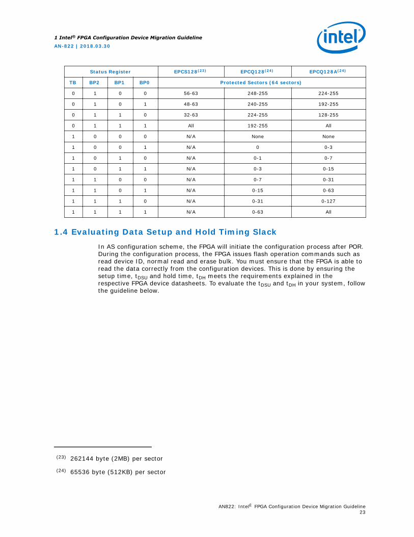
Table 20. Sector Protect Comparison for EPCS128, EPCQ128 and EPCQ128A Devices
Status Register EPCS128(23) EPCQ128(24) EPCQ128A(24)
TB BP2 BP1 BP0 Protected Sectors (64 sectors)
0 0 0 0 None None None
0 0 0 1 63 255 252-255
0 0 1 0 62-63 254-255 248-255
0 0 1 1 60-63 252-255 240-255
continued...
(23) 262144 byte (2MB) per sector
(24) 65536 byte (512KB) per sector
1 Intel® FPGA Configuration Device Migration Guideline
AN-822 | 2018.03.30
AN822: Intel® FPGA Configuration Device Migration Guideline22
Status Register EPCS128(23) EPCQ128(24) EPCQ128A(24)
TB BP2 BP1 BP0 Protected Sectors (64 sectors)
0 1 0 0 56-63 248-255 224-255
0 1 0 1 48-63 240-255 192-255
0 1 1 0 32-63 224-255 128-255
0 1 1 1 All 192-255 All
1 0 0 0 N/A None None
1 0 0 1 N/A 0 0-3
1 0 1 0 N/A 0-1 0-7
1 0 1 1 N/A 0-3 0-15
1 1 0 0 N/A 0-7 0-31
1 1 0 1 N/A 0-15 0-63
1 1 1 0 N/A 0-31 0-127
1 1 1 1 N/A 0-63 All
1.4 Evaluating Data Setup and Hold Timing Slack
In AS configuration scheme, the FPGA will initiate the configuration process after POR.During the configuration process, the FPGA issues flash operation commands such asread device ID, normal read and erase bulk. You must ensure that the FPGA is able toread the data correctly from the configuration devices. This is done by ensuring thesetup time, tDSU and hold time, tDH meets the requirements explained in therespective FPGA device datasheets. To evaluate the tDSU and tDH in your system, followthe guideline below.
(23) 262144 byte (2MB) per sector
(24) 65536 byte (512KB) per sector
1 Intel® FPGA Configuration Device Migration Guideline
AN-822 | 2018.03.30
AN822: Intel® FPGA Configuration Device Migration Guideline23
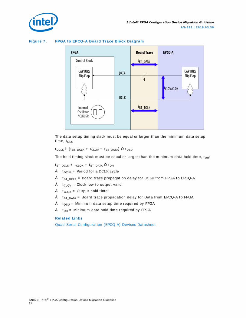
Figure 7. FPGA to EPCQ-A Board Trace Block Diagram
FPGA Board Trace EPCQ-A
Control Block
DATA
tBT_DATA
tCLQV/CLQX
4
DCLK
InternalOscillator/ CLKUSR
tBT_DCLK
CAPTUREFlip Flop
CAPTUREFlip Flop
The data setup timing slack must be equal or larger than the minimum data setuptime, tDSU
tDCLK – (tBT_DCLK + tCLQV + tBT_DATA) ≥ tDSU
The hold timing slack must be equal or larger than the minimum data hold time, tDH:
tBT_DCLK + tCLQX + tBT_DATA ≥ tDH
• tDCLK = Period for a DCLK cycle
• tBT_DCLK = Board trace propagation delay for DCLK from FPGA to EPCQ-A
• tCLQV = Clock low to output valid
• tCLQX = Output hold time
• tBT_DATA = Board trace propagation delay for Data from EPCQ-A to FPGA
• tDSU = Minimum data setup time required by FPGA
• tDH = Minimum data hold time required by FPGA
Related Links
Quad-Serial Configuration (EPCQ-A) Devices Datasheet
1 Intel® FPGA Configuration Device Migration Guideline
AN-822 | 2018.03.30
AN822: Intel® FPGA Configuration Device Migration Guideline24
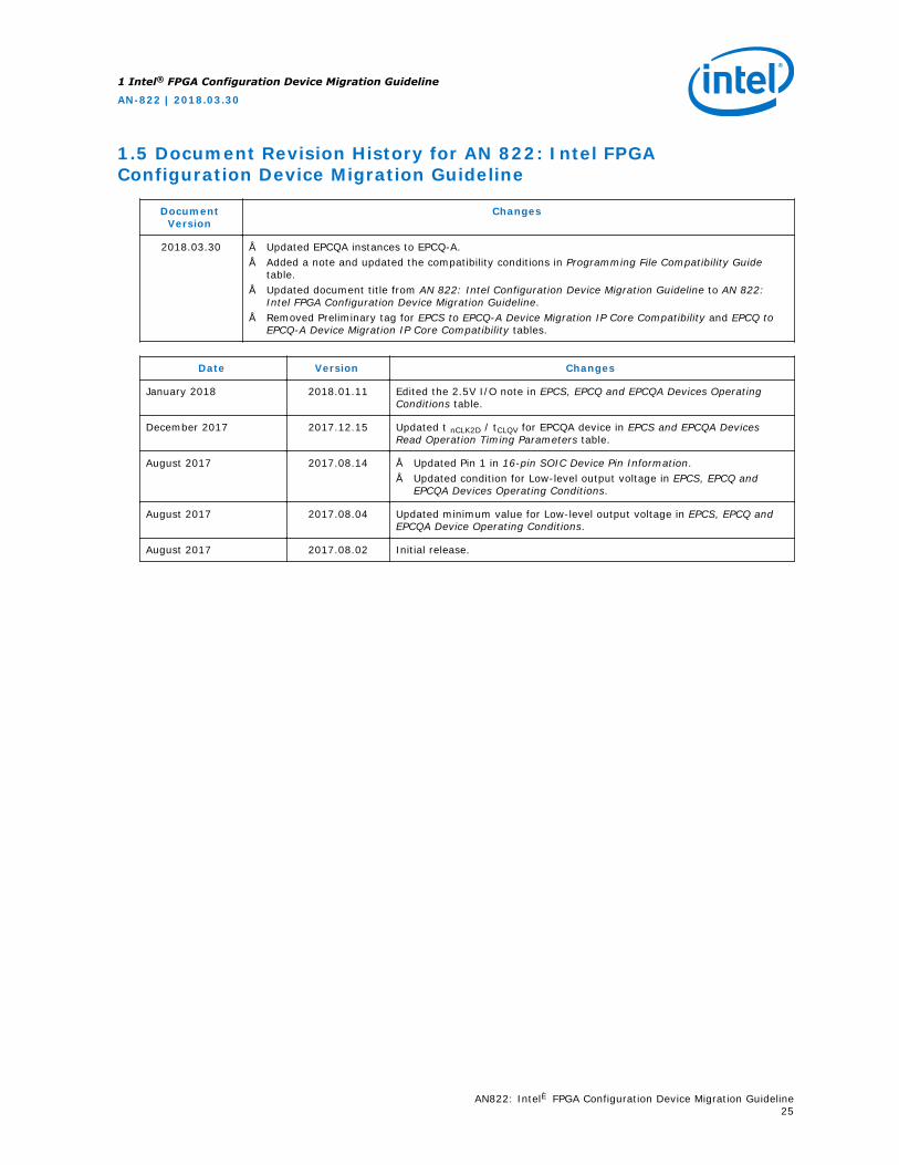
1.5 Document Revision History for AN 822: Intel FPGAConfiguration Device Migration Guideline
DocumentVersion
Changes
2018.03.30 • Updated EPCQA instances to EPCQ-A.• Added a note and updated the compatibility conditions in Programming File Compatibility Guide
table.• Updated document title from AN 822: Intel Configuration Device Migration Guideline to AN 822:
Intel FPGA Configuration Device Migration Guideline.• Removed Preliminary tag for EPCS to EPCQ-A Device Migration IP Core Compatibility and EPCQ to
EPCQ-A Device Migration IP Core Compatibility tables.
Date Version Changes
January 2018 2018.01.11 Edited the 2.5V I/O note in EPCS, EPCQ and EPCQA Devices OperatingConditions table.
December 2017 2017.12.15 Updated t nCLK2D / tCLQV for EPCQA device in EPCS and EPCQA DevicesRead Operation Timing Parameters table.
August 2017 2017.08.14 • Updated Pin 1 in 16-pin SOIC Device Pin Information.• Updated condition for Low-level output voltage in EPCS, EPCQ and
EPCQA Devices Operating Conditions.
August 2017 2017.08.04 Updated minimum value for Low-level output voltage in EPCS, EPCQ andEPCQA Device Operating Conditions.
August 2017 2017.08.02 Initial release.
1 Intel® FPGA Configuration Device Migration Guideline
AN-822 | 2018.03.30
AN822: Intel® FPGA Configuration Device Migration Guideline25