Embed Size (px)
DESCRIPTION
app not mpc
Citation preview

1 IntroductionThis application note details the concepts and steps required touse the Fast Ethernet Controller (FEC) module on FreescaleQorivva MPC564xB/C devices. It focuses on using FreescaleEVBs but the information on module configuration and PHYconnection readily transfers to other designs. The informationand activities in this application note can also be applied toother Freescale devices containing the FEC.
Because of their speed and flexibility, Ethernet networks areseeing increasing adoption within vehicle systems forcommunication between Electronic Control Units (ECUs) andin-vehicle systems. Freescale has built its FEC module ontoseveral auto-qualified parts and, in this application note,describe the use of this module.
We will begin by describing the physical signals that areproduced by the FEC, give an overview of structures andterminology used in Ethernet networking, and then provideseveral example applications. While this application note istargeted at MPC564xB/C, the same module is available onother parts, such as MPC5668G, MPC5604E, andMPC567xK. The FNET for PPC port provided with thisapplication note supports these devices, and examples 2–4 willalso function on these devices. Example 1 relies on modulesnot available on all of these devices, but porting this examplemay be a useful learning exercise.
Freescale Semiconductor Document Number:AN4577
Application Note Rev. 0, December 2012
Using the Fast Ethernet Controlleron the Qorivva MPC564xB/Cby: Gordon Jahn
© 2012 Freescale Semiconductor, Inc.
Contents
1 Introduction................................................................1
2 Ethernet physical signals...........................................2
2.1 MII versus MII-Lite.......................................2
3 The network stack.....................................................3
3.1 The Internet protocol......................................3
3.2 Encapsulation.................................................4
3.3 Addressing in Ethernet networks ...................5
4 Examples...................................................................5
4.1 Example 1: A simple Ethernetproject............................................................6
4.2 Example 2 – UDP datatransmission.................................................12
4.3 Example 3 – TCP communication. ..............13
4.4 Example 4 – The FNET web server.............15
A Configuration information for FNETProjects....................................................................22
B A Java UDP Client for Example 2 .........................22

2 Ethernet physical signalsEthernet is a commodity networking technology that allows messages to be passed between multiple nodes on the samenetwork. Comparing Ethernet to Controller Area Network (CAN) busses, Ethernet allows for much higher data transferspeeds than CAN.
Ethernet is a low-level networking protocol that transmits a frame onto a physical layer. The physical layer for Fast Ethernetcommonly uses two twisted pairs, one for transmission and one for reception, although some proprietary physical layers canoperate over a single pair.
Each device within an Ethernet segment must have a unique 48-bit identifier, called the Media Access Control (MAC)address. In order to communicate using Ethernet, an Ethernet frame must be constructed on the device and sent from the localMAC address to another Ethernet address. Ethernet addressing is described in more detail in Addressing in Ethernetnetworks.
The FEC module is programmed with the local and group addresses to receive, and only frames addressed to the host will bereceived by the FEC and cause a receive interrupt.
The function of the hardware FEC deals with ensuring that a frame is successfully transmitted and can also append the CRC,which is calculated in hardware. In the event of other devices using the bus, the FEC will wait until the bus is quiet beforeattempting transmission. If two nodes attempt to transmit at the same time, both will back off for a random time period beforeretrying. This is known as a Carrier Sense Multiple Access with Collision Detect scheme (CSMA/CD).
The physical signals applied on a wired Ethernet segment are –0.85 to 0.85 V and bits are Manchester-encoded. This alwaysresults in a mean voltage of 0 V on the line.
The connection from the MAC block inside the MPC56xx part to the Ethernet PHY should be made at 3.3 V using the MediaIndependent Interface (MII). For MPC564xB/C parts, the VDD_HV_B supply on the EVB should be set to 3.3 V (J12 in the2–3 position). Where the same 3.3 V supply is used for the MCU and the PHY, no impedance matching resistors arerequired.
2.1 MII versus MII-LiteSome physical transceivers (PHYs) do not have all the MII pins and signals that are available on the MPC564xB/C FEC.This connection between the MAC and PHY is known as MII-Lite. This connection should not be confused with RMII, adifferent standard for reducing signals. RMI is not supported by these parts.
Signals that may be omitted in MII-Lite are TX_ER, RX_ER, COL, and CRS. The recommended settings for these pins andsignals are described here.
TX_ERThis FEC output can be left unconfigured and unused. The pin was originally included for the test case in some PHYdesigns where the MAC layer in the FEC can demand that the PHY corrupt data during transmission. However, it isreadily possible to do this within the MAC by setting the ABC (Append Bad CRC) bit in the transmit buffer descriptor(TxBD) for the frame being sent.
RX_ERThis pin is asserted high by the PHY to signal an error to the MAC. However, in these circumstances the PHY willdeliberately corrupt the CRC of the incoming frame before passing to the MAC. This input to the MCU can therefore bepulled low and any RX_ER can be detected by a CRC error in the received frame where the CR bit is set in the receivebuffer descriptor (RxBD).
COLThis pin is asserted by the PHY when there has been a collision. With full-duplex links, this would always be low, so thispin's absence implies either that the link is full-duplex or that collisions are handled internally within the PHY. The signalis only asserted high on simultaneous Rx and Tx on half-duplex links. As this must be handled by the PHY if the signal isnot available, it can be safely pulled low on the board.
Ethernet physical signals
Using the Fast Ethernet Controller on the Qorivva MPC564xB/C, Rev. 0, December 2012
2 Freescale Semiconductor, Inc.

CRSCarrier sense is asserted high by the PHY to indicate that the receive medium is non-idle. As is the case with the COLsignal, this never occurs with full-duplex links. Again, it is recommended that this signal be pulled low using an externalpulldown.
3 The network stackIn order to use the FEC to communicate with other devices, the microcontroller must be programmed with protocols. Theseaim to allow applications to be completely media-agnostic and allow several applications on a host to use the same networkadapter. Protocols at different layers within the stack aim to keep underlying implementations completely transparent tolayers above. It is this property that, for example, allowed Ethernet to move from coaxial cable to twisted pairs, and allowsthe same services to run across fibre-optic and wireless links without modification.
The International Standards Organisation (ISO) Open Systems Interconnection (OSI) reference model defines seven layers;these are:
• Application• Presentation• Session• Transport• Network• Data link• Physical
The microcontroller’s FEC implementation handles the Data link layer plus passing and retrieving information to and fromthe Physical layer.
3.1 The Internet protocolTCP/IP is the name commonly given to the suite of protocols that were developed for ARPANET, the forerunner to theInternet. TCP and IP are, however, distinct protocols in their own right at different layers within the network stack. Alongwith the Address Resolution Protocol (ARP) and higher level application protocols, such as the Domain Name Service(DNS), the HyperText Transfer Protocol (HTTP), and the Dynamic Host Configuration Protocol (DHCP), full interactionwith existing IP equipment can be provided.
The seven layers of the OSI reference model are not all present in the IP. Instead the data link and physical layers are treatedas a single host-to-network layer and the Internet Protocol (IP) maps closely to the Network layer in the OSI model. The UserDatagram Protocol (UDP) and TCP are both Transport layers whilst the session and presentation layers are omitted in TCP/IPbut may be provided as middleware. The application layer, where the user application runs, is present in both models. Thismapping is shown in Figure 1.
The network stack
Using the Fast Ethernet Controller on the Qorivva MPC564xB/C, Rev. 0, December 2012
Freescale Semiconductor, Inc. 3

Figure 1. Comparing OSI and TCP/IP layers
Within any network stack, data from the application layer is transformed as it moves down the stack. The Transport layer, forexample, splits up large data streams, such as an image file being sent by a web server, into smaller packets that can betransferred within a 1.5 KB Ethernet frame. The transport layer on the receiving side is then responsible for reconstructingthe original stream; for example, presenting the image to the web browser application for display to the user. The process oftaking data from a higher layer and adding the appropriate additional information to allow things like reconstruction androuting is known as encapsulation.
3.2 EncapsulationAs data moves from the application layer to the physical layer within a network stack, it must be encapsulated within furtherprotocols.
With the Internet Protocol suite, the application designer chooses how to encapsulate data; two generic options that areapplicable to most situations are given to the application designer: the User Datagram Protocol (UDP) and the TransportControl Protocol (TCP).
Each of these has different properties. UDP is a stateless protocol that does not guarantee delivery of packets, order ofpackets, or that the data delivered has not been corrupted. Because there’s no need to maintain connection information, UDPdatagrams can be handled quickly. They are most useful where speed and latency matter, such as handling DNS requests.UDP also allows data to be sent to multiple hosts at the same time using multicast.
TCP, on the other hand, provides a link between exactly two hosts for sending and receiving datagrams. It guarantees thatdata can be exchanged in both directions, while also providing acknowledgements when datagrams have been delivered andthat the data is correct. The cost of TCP, however, is that significant time can be consumed setting up the initial connectionbefore any data can be exchanged.
In designing an IP-based communications mechanism, an good understanding of the difference between UDP and TCPencapsulation, and of the advantages and disadvantages of each, is worthwhile. From a microcontroller point of view,designing an application to use only UDP communication will save the memory footprint associated with maintaining TCPconnections.
The network stack
Using the Fast Ethernet Controller on the Qorivva MPC564xB/C, Rev. 0, December 2012
4 Freescale Semiconductor, Inc.

3.3 Addressing in Ethernet networksThe examples within this application note refer to two different addressing schemes:
• IP addressing• Ethernet addressing
Ethernet addresses, also known as hardware or Media Access Control (MAC) addresses, are 48-bit hardware addresses. Theyare formed using three octets which identify the organization providing the device (the Organizationally Unique Identifier orOUI) followed by 3 octets identifying the device. It is generally intended that these addresses are unique but it is sufficientfor all devices on a single Ethernet segment to have unique addresses.
The least significant bit in the most significant octet — that which would be the first octet of the OUI — also plays a specialrole in identifying multicast packets. Any Ethernet frames with this bit set can be accepted by all nodes and the address withall bits set, FF:FF:FF:FF:FF:FF, is known as the broadcast address that should be accepted by all nodes.
The examples contained within this document use the Freescale OUI (00:04:9F) as the upper three octets with a randomlygenerated lower three octets. Companies that use Freescale microcontrollers within their products are expected to programthe MAC address of their devices accordingly.
Ethernet addresses are used for all communication between nodes within an Ethernet segment. The relationship between IPaddresses on an Ethernet network and Ethernet addresses is therefore that Ethernet is required to carry the IP datagrams to theappropriate next node. This could be directly to a destination node, or it could be to a router that will then pass to adestination node or another router. Subsequent hops may not even use Ethernet, and a different physical layer may be used totransport IP datagrams. Whilst routing and other physical transmission mediums are beyond the scope of this document, it issufficient to point out that in order to use IP on Ethernet, both an Ethernet address and IP address are required.
The protocol for obtaining a TCP/IP address is known as the Dynamic Host Configuration Protocol (DHCP) and the protocolused to discover Ethernet addresses from IP addresses is known as the Address Resolution Protocol (ARP). Both of theseprotocols use a combination of broadcast and unicast transmissions to communicate with other nodes attached to the Ethernetsegment.
4 ExamplesIn the first example, a simple project is developed that initializes the FEC and sends data as a 32-bit number via the Ethernetinterface. In examples 2–4, the FNET TCP/IP library (modified from the sources available at http://fnet.sourceforge.net) hasbeen used to demonstrate the operation of higher-layer protocols. The documentation found on this site will provide a usefulreference for those wishing to understand the FNET examples in more detail.
NOTEThe FNET codebase with MPC56xx support provided as a resource for this applicationnote does not contain flash driver support, and is not licensed under the same terms as thecode found on the SourceForge site.
The application note will provide several examples showing how networking functionality can be built on MPC56xxmicrocontrollers. The examples are as follows:
• A simple 2-node network that transmits data within an Ethernet frame to the broadcast address making it available toall nodes; no higher-layer protocol is employed.
• An implementation of IP showing how the microcontroller can be connected to a standard IP network to retrieve an IPaddress and share data between hosts using a UDP protocol.
• An implementation of IP showing how the microcontroller can be connected to a standard IP network to retrieve an IPaddress, then listen for, and respond over, a TCP connection.
• An implementation of a simple HTTP server that can display values read from the internal ADC on a web page and thatcan flash LEDs on the EVB under control of a web browser.
Examples
Using the Fast Ethernet Controller on the Qorivva MPC564xB/C, Rev. 0, December 2012
Freescale Semiconductor, Inc. 5

NOTEPlease read Configuration information for FNET Projects before implementing theexamples to ensure that your CodeWarrior setup is correct.
4.1 Example 1: A simple Ethernet projectThis project uses two microcontroller EVBs with Ethernet. The goal of this project is to understand:
• The basic operation of the FEC.• How to build Ethernet frames for transmission.• How to receive frames from the physical media.
This project runs the microcontroller at 64 MHz. These steps are implemented:
1. Setting up GPIO2. Bringing up the FEC module3. Configuring the Media Independent Interface (MII)4. Configuring the send and receive descriptors and buffers5. Configuring the interrupt controller to handle incoming frames6. Sending and receiving frames7. Configuring the ADC to sample data and eMIOS to output a PWM signal
This simple project provides a base upon which more complex protocols can be implemented. The basic functionalityexhibited in this project is then shown in the examples where higher layers in the stack are constructed.
This project implements the simple flow shown. Data is captured on each board using the ADC. The value captured is placedinto an Ethernet packet and sent via the FEC to the Ethernet broadcast address FF:FF:FF:FF:FF:FF. On receipt of a packet,the value is extracted from the packet and alters an eMIOS duty cycle to change the brightness of an LED.
Figure 2. Example 1 — Information flow
This scenario allows two boards to be connected together using a single network cable. They will both send data at the sametime. The potentiometer on one board will control the brightness of an LED on another board as long as J8-2 is wired toPJ5-4 and PJ4-0 is wired to PJ8-4.
Examples
Using the Fast Ethernet Controller on the Qorivva MPC564xB/C, Rev. 0, December 2012
6 Freescale Semiconductor, Inc.

4.1.1 Setting up GPIORegardless of the device being used, GPIO must be configured. For the MPC564xB/C devices, the configuration shown inTable 1 is required.
Table 1. GPIO configuration
Signal I/O from (MAC) Port PCR PCR value
RX_CLK I A3 3 0x106
RXD2 I A7 7 0x106
RXD1 I A8 8 0x106
RXD0 I A9 9 0x106
COL I A10 10 0x106
RX_ER I A11 11 0x106
CRS I E12 76 0x106
RXD3 I E13 77 0x106
MDIO I/O F14 94 0x1306
RX_DV I F15 95 0x102
MDC O G0 96 0x1202
TX_CLK I G1 97 0x102
TXD2 O G12 108 0x1204
TXD3 O G13 109 0x1204
TXD1 O H0 112 0x1204
TXD0 O H1 113 0x1204
TX_EN O H2 114 0x1204
TX_ER O H3 115 0x1204
The following code is used to set up the GPIO on an MPC564xB/C device, as described in the table.
// initFecIo - initialise pads for FEC use in the SIUvoid initFecIo(){ SIU.PCR[94].R = 0x1306; /* Set to FEC_MDIO */ SIU.PCR[96].R = 0x1202; /* Set to FEC_MDC */ SIU.PCR[114].R = 0x1204; /* Set to FEC_TX_EN */ SIU.PCR[113].R = 0x1204; /* Set to FEC_TXD[0] */ SIU.PCR[112].R = 0x1204; /* Set to FEC_TXD[1] */ SIU.PCR[108].R = 0x1204; /* Set to FEC_TXD[2] */ SIU.PCR[109].R = 0x1204; /* Set to FEC_TXD[3] */ SIU.PCR[115].R = 0x1204; /* Set to FEC_TX_ER */ SIU.PCR[10].R = 0x106; /* Set to FEC_COL */ SIU.PCR[97].R = 0x102; /* Set to FEC_TX_CLK */ SIU.PCR[76].R = 0x106; /* Set to FEC_CRS */ SIU.PCR[3].R = 0x106; /* Set to FEC_RX_CLK */ SIU.PCR[95].R = 0x102; /* Set to FEC_RX_DV */ SIU.PCR[9].R = 0x106; /* Set to FEC_RXD[0] */ SIU.PCR[8].R = 0x106; /* Set to FEC_RXD[1] */ SIU.PCR[7].R = 0x106; /* Set to FEC_RXD[2] */ SIU.PCR[77].R = 0x106; /* Set to FEC_RXD[3] */ SIU.PCR[11].R = 0x106; /* Set to FEC_RX_ER */}
Examples
Using the Fast Ethernet Controller on the Qorivva MPC564xB/C, Rev. 0, December 2012
Freescale Semiconductor, Inc. 7
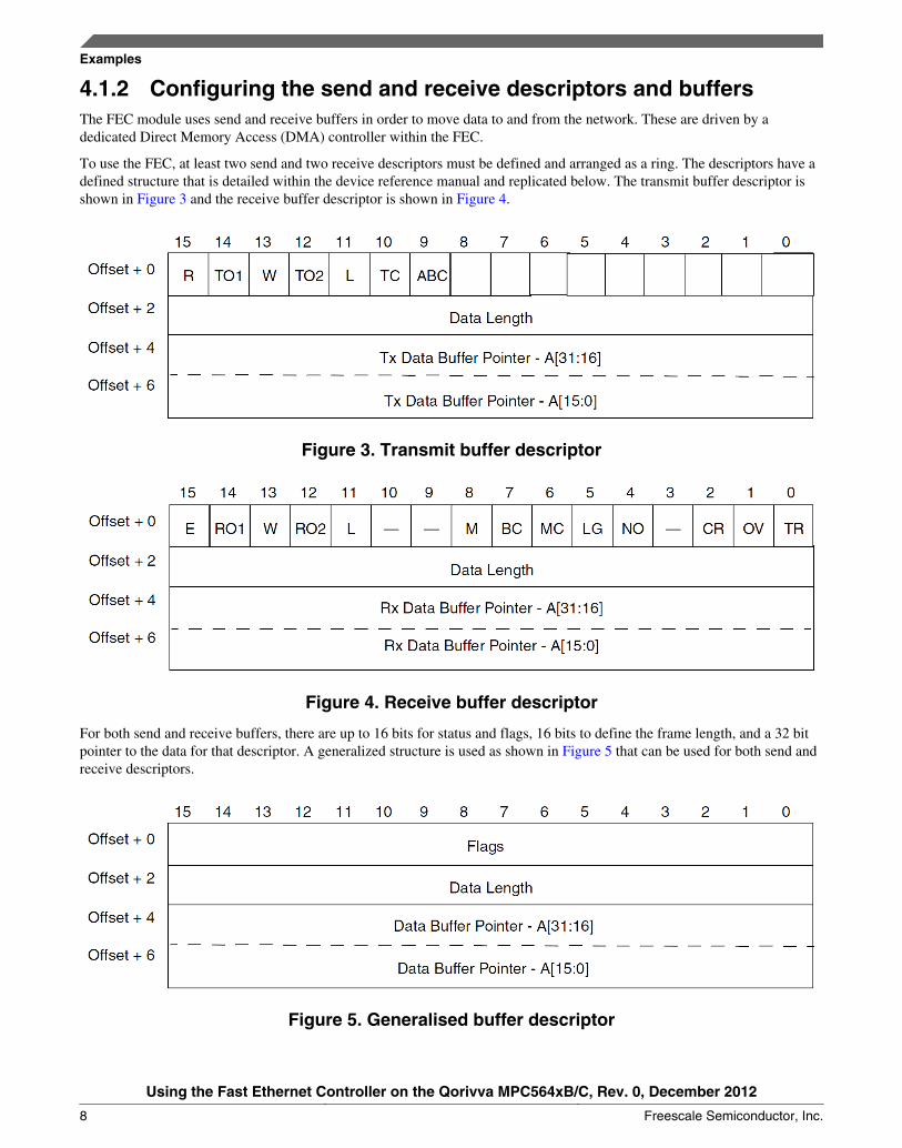
4.1.2 Configuring the send and receive descriptors and buffersThe FEC module uses send and receive buffers in order to move data to and from the network. These are driven by adedicated Direct Memory Access (DMA) controller within the FEC.
To use the FEC, at least two send and two receive descriptors must be defined and arranged as a ring. The descriptors have adefined structure that is detailed within the device reference manual and replicated below. The transmit buffer descriptor isshown in Figure 3 and the receive buffer descriptor is shown in Figure 4.
Figure 3. Transmit buffer descriptor
Figure 4. Receive buffer descriptor
For both send and receive buffers, there are up to 16 bits for status and flags, 16 bits to define the frame length, and a 32 bitpointer to the data for that descriptor. A generalized structure is used as shown in Figure 5 that can be used for both send andreceive descriptors.
Figure 5. Generalised buffer descriptor
Examples
Using the Fast Ethernet Controller on the Qorivva MPC564xB/C, Rev. 0, December 2012
8 Freescale Semiconductor, Inc.

A struct that can be used for both the send and receive descriptor is shown below. The status information must be declaredvolatile as the FEC hardware modifies this value.
typedef struct{ volatile unsigned short status; /* Control and status info.*/ unsigned short length; /* Data length.*/ unsigned char *bufferPointer; /* Buffer pointer.*/}BufferDescriptor;
Multiple descriptors can be used to hold the data for a single frame, although in this example a single descriptor is used forthe whole frame. Bringing up the FEC involves resetting all required fields within the FEC and setting up the descriptorsready for use, as shown in the next section.
The transmit and receive buffers need to be arranged within a ring buffer structure. The ring buffer can be as big as RAMallows, but must contain at least two descriptors. The last descriptor within the ring must set the Wrap bit, bit 13 in bothdescriptor flags, so that the FEC hardware knows when to return to the first descriptor. Then the application must track whichbuffer is written or read.
4.1.3 Bringing up the FEC moduleHaving configured the IO, the FEC module itself, along with the physical transceiver, can be set up. Note that prior toinitializing, the FEC clock divider is disabled, thus ensuring that a 64 MHz clock is passed to the FEC(CGM.FEC_DCR.R = 0x0). When the system speed is greater than 100 MHz, the divider must be used. The code for this isshown below:
CGM.FEC_DCR.R = 0x0;
The process to bring up the module then involves resetting the module and configuring the hardware with its hardwareaddress. This will ensure that it will automatically filter frames, presenting only the appropriate ones to the host.
The code used by the example is shown and explained below; the steps required are also described within the MPC5646Creference manual. The functionality is grouped within the description here but, as noted in the reference manual, steps may beperformed in any order.
FEC.ECR.R = 0x1; // Start resetwhile (FEC.ECR.B.RESET) { }; // Wait for reset to complete
FEC.EIMR.R = 0; // Disable interruptsFEC.EIR.R = 0xFFFFFFFF; // Clear any interrupts
Next, the address recognition registers can be configured. Whilst the FEC will always accept broadcast address frames andcan be configured in promiscuous mode to receive all frames, acceptance of other frames is configured by the group,individual, and physical address registers. With upper and lower registers for each, these correspond to the GAUR/GALR,IAUR/IALR, and PAUR/PALR registers respectively.
// Reset multicast fieldsFEC.GAUR.R = 0;FEC.GALR.R = 0;FEC.IAUR.R = 0;FEC.IALR.R = 0;
// Configure a MAC addressFEC.PALR.R = (unsigned long)((mac[0] <<24)|(mac[1] <<16)|(mac[2] <<8)|(mac[3] <<0));FEC.PAUR.R = (unsigned long)(mac[4] <<24)|(mac[5] <<16);
The recognition of addresses is, again, fully described within the reference manual, but setting the GAUR/GALR and IAUR/IALR values to zero prevents any matching using the hashing algorithm implemented within hardware in the FEC. Thismeans that the only frames that will be accepted are broadcast frames (with destination address FF:FF:FF:FF:FF:FF) or thosewith a destination address exactly matching the physical address configured in PAUR/PALR .
Examples
Using the Fast Ethernet Controller on the Qorivva MPC564xB/C, Rev. 0, December 2012
Freescale Semiconductor, Inc. 9

The FEC uses buffers in RAM to both send and receive data. More information on these is provided in Configuring the sendand receive descriptors and buffers . These are configured within the FEC initialization, and the ETDSR and ERDSR(Transmit and Receive Descriptor Ring Buffer Start addresses) are set.
This final configuration required for the ring buffer is to describe the size of the receive buffer to ensure that the FEC doesnot overwrite memory that it should not access.
for (i = 0; i < 2; i++) { // Init tx and rx descriptors txDesc[i].status = 0x2C00;// Last and transmit CRC txDesc[i].length = 0; txDesc[i].bufferPointer = txBuf;
markRxDescEmpty(&rxDesc[i]); rxDesc[i].bufferPointer = rxBuf[i];}
// Point FEC to our (single) tx and rx descriptorsFEC.ETDSR.R = (unsigned long) &txDesc;FEC.ERDSR.R = (unsigned long) &rxDesc;
// Set rx buf sizeFEC.EMRBR.R = 1536;
Final configuration for the module then enables full duplex, sets the Receive Configuration Register (RCR) for either receiptfrom the network or loopback mode (useful when testing with a single board), enables the receive interrupt and enables themodule.
// Enable full duplex FEC.TCR.R = 0x00000004;
#if USE_LOOPBACK // In loopback, unset DRT and set LOOP in RCR FEC.RCR.R = 0x05EE0001;#else // Set in MII mode with full frame size FEC.RCR.R = 0x05EE0004;
// Set MII speed - assume operation at 64Mhz FEC.MSCR.B.MII_SPEED = 0xD;#endif
// Enable interruptFEC.EIMR.R = 0x02000000;
// Enable moduleFEC.ECR.R = 0x2;
At this point, the FEC module has been configured and can now be used to set up the connected PHY using the MediaIndependent Interface.
4.1.4 Configuring the Media Independent Interface (MII)The FEC does not generate the physical signals directly, but rather uses the Media Independent Interface (MII) standard tocommunicate with a physical interface (PHY). The PHY used on Freescale boards is a Texas Instruments/NationalDP83848VYB.
In order to use the PHY, it must be configured. The FEC supports up to 32 PHYs and in order to locate the address in use, asimple scan of the possible 32 channels is used. After a responding PHY is found, the address is stored and used.
Examples
Using the Fast Ethernet Controller on the Qorivva MPC564xB/C, Rev. 0, December 2012
10 Freescale Semiconductor, Inc.

The MII management interface operates at no greater than 2.5 MHz, and all communication is handled via the FEC MediaManagement Frame Register (MMFR). The FEC is configured to divide the clock to achieve this constraint; note that thisdoes not limit the TX and RX clock speeds which can independently run at up to 25 Mhz to achieve the 100 Mbit data linespeed.
The setup used in this case writes to register 0x19 on the PHY to enable MDI-X mode. This allows for a straight cable to beused between the two boards and the PHYs will automatically negotiate the appropriate pairs within the cable to use. Havingset up the MDI-X, the code requests that the PHY restart auto-negotiation to achieve 100 Mbit full-duplex operation. Theremaining projects in the document do not set up MDI-X mode as it is expected these will be used with a router orinfrastructure providing DHCP services.
The sample code contains functions to read and write to the PHY registers via the MII management interface provided on theFast Ethernet Controller, and to use these functions to discover the PHY address. The high-level function setting up the PHYis shown below.
// initFecPhy - setup the PHYvoid initFecPhy() { uint16_t regValue; uint16_t statusValue = 0;
findPhyAddress();
// Enable MDIX mode - this allows us to connect Part-Part miiRead(0x0019, ®Value); miiWrite(0x0019, (uint16_t) (regValue | 0x8000));
// Enable and restart auto-negotiation miiRead(0x0000, ®Value); miiWrite(0x0000, (uint16_t) (regValue | 0x1200));
// Wait for Auto-Neg complete flag while (statusValue != 0x0020) { miiRead(0x0001, &statusValue); statusValue &= 0x0020; }}
4.1.5 Configuring the interrupt controllerThe interrupt controller is configured as any other interrupt would be. Only the frame receipt interrupt is configured. Withinthis project, the CodeWarrior template functions are used for this; the relevant code is shown below.
// Setup interrupts (rx frame handling)INTC_InitINTCInterrupts();INTC.CPR_PRC0.B.PRI = 0;INTC_InstallINTCInterruptHandler(rxEthernetFrame, 245, 10);
4.1.6 Sending a frameThe frame to be sent needs to contain the required Ethernet headers along with any payload data. In this example, a struct(MyEthernetFrame) has been coded to represent the frame containing the destination and source addresses, the length, anda sample value. The destination has been hard-coded as the Ethernet broadcast address FF:FF:FF:FF:FF:FF, and the sourceaddress is a MAC that begins with 00:04:9F (the Freescale OUI) followed by bits sourced from the STM module on thedevice.
The ADC has been programmed in one-shot mode reading port PB4. The main program loop takes a sample from the ADC,inserts the value into the structure, and flags the message buffer for sending.
Examples
Using the Fast Ethernet Controller on the Qorivva MPC564xB/C, Rev. 0, December 2012
Freescale Semiconductor, Inc. 11

The message buffer flags are set to 0x8C00. This sets the descriptor as being ready to send, that this is the last descriptor forthe frame being sent, and requests that the FEC compute and transmit the CRC for this frame. Additionally, if the descriptoris the last one in the ring then the WRAP flag is set. Finally, the TDAR register is set to 0x01000000 to flag to the hardwarethat a new transmit descriptor is ready for transmission.
As the TC flag has been set, the FEC automatically pads the short frame to the minimum length and appends the CRC.
4.1.7 Receiving dataOn receipt of an Ethernet frame, the core is interrupted to process the message. The interrupt handler casts the incoming bytedata to a MyEthernetFrame struct and checks the source address. If the OUI matches the Freescale value shown above, thepart extracts the value from the sample field and uses this as an eMIOS duty counter on PA0. This is used to drive an LED atvarying brightness.
Having processed each frame, the buffer that has been used is then marked as empty by setting the Empty flag (bit 13 in theflags Figure 4), and the length field of the descriptor is reset to zero. If the receive descriptor is the last one in the ring, theWRAP flag is also set. Finally, 0x01000000 is written to the RDAR register to flag to the FEC hardware that a new receivedescriptor is available. If no empty receive descriptors are available, then the FEC will silently drop the incoming frame.
The final action of the interrupt handler is to clear the interrupt and return.
4.1.8 Loopback modeThe project can also be set up to operate on a single board. By changing the value of the #define USE_LOOPBACK (0) from0 to 1 in fec.c, the FEC will be placed in loopback mode without requiring a connection via the MII to a PHY. In this case,the frames are received locally so the potentiometer controls the brightness of the local board's LED.
4.2 Example 2 – UDP data transmissionNOTE
Please refer to Configuration information for FNET Projects for further information onhow to set up and run this demonstration.
This example utilizes the UDP protocol to send data from the MPC564xB/C part. You must install the FNET for PPCinstallation and accept the license agreement in order to use this example. After installation, open the CodeWarrior projectwithin Example2.zip and drag-and-drop the fnet_stack directory into the source tree for the project.
This project sets up the FNET stack on the microcontroller, and requests an IP address via DHCP. Having set up the stack, aclient machine can send a UDP packet to the microcontroller, on port 1080, containing 8 bytes. The first 4 bytes (a signed int)are interpreted as a port number and the second 4 bytes as a command. The only commands implemented are “0” for off and“1” for on. On receipt of a command, the micro configures the requested port for output and writes the value via GPIO. Usinga port number required for Ethernet will stop the example functioning.
The fnet_user_config.h file for this project disables the TCP support leaving DHCP and UDP support enabled.
The example code contains code that sets up the part for 120 MHz operation and turns off the watchdog. The code to performthis application is:
INTC_InitINTCInterrupts();INTC.CPR_PRC0.B.PRI = 0;
if (fnet_init_static() != FNET_ERR) { fnet_dhcp_init(fnet_netif_find_name("eth0"), 0);
// Step 1 Create a socket
Examples
Using the Fast Ethernet Controller on the Qorivva MPC564xB/C, Rev. 0, December 2012
12 Freescale Semiconductor, Inc.

main_socket = socket(AF_INET, SOCK_DGRAM, 0);
// Step 2 Create a sockaddr_in to describe the local port local_info.sin_len = sizeof(local_info); local_info.sin_family = AF_INET; local_info.sin_addr.s_addr = fnet_htonl(INADDR_ANY); local_info.sin_port = fnet_htons(PORT_NUMBER);
remote_info.sin_family = AF_INET;
// Step 3 Bind the socket to the port int r = bind(main_socket, (struct sockaddr *) &local_info, sizeof(local_info));
while(1) { // Step 4 Check for packet r = recvfrom(main_socket, (char *) &command, sizeof(command), 0, (struct sockaddr *) &remote_info, &remote_info_len);
// Step 5 If packet found, process if (r > 0) { // Make port output and set to !command SIU.PCR[command.portNumber].R = 0x200; SIU.GPDO[command.portNumber].R = !command.command;
r = sendto(main_socket, message, sizeof(message), 0, (struct sockaddr *) &remote_info, sizeof(remote_info)); }
// Step 6 Process any FNET services (i.e. DHCP) fnet_poll(); }}
A sample console-based Java application that can write using this protocol and that will display the message (“OK”) returnedby the microcontroller is shown in A Java UDP Client for Example 2 .
4.3 Example 3 – TCP communicationNOTE
Please refer to Configuration information for FNET Projects for further information onhow to set up and run this demonstration.
This example uses the UDP protocol to send data from the MPC564xB/C part. You must install the FNET for PPCinstallation and accept the license agreement in order to use this example. After installation, open the CodeWarrior projectwithin Example3.zip and drag-and-drop the fnet_stack directory into the source tree.
This example uses the FNET TCP/IP stack to perform the following steps:
1. Initialize the FNET stack.2. Run DHCP to acquire an IP address for the MCU.3. Create a socket listening on port 1080.4. On connection, read a line of up to 80 characters and echo back .5. Close connection and repeat previous step.
The layout of this code is similar to BSD socket programming; as with all TCP connections, there is no concept of a“message,” so the TCP protocol employed has to be able to identify when a message is complete. The method used withinthis example is to use a readline function that reads up to a carriage return within the input stream.
The example here reads from the inbound TCP stream until a carriage return and then simply echoes the same message backto the outbound TCP stream.
The fnet_user_config.h file for this project enables the TCP support that was disabled in example 2; UDP remains enabled toallow the part to obtain an IP address using DHCP.
Examples
Using the Fast Ethernet Controller on the Qorivva MPC564xB/C, Rev. 0, December 2012
Freescale Semiconductor, Inc. 13

The readline function used is shown below.
void readline(int connection, char *mainbuffer, int maxbuffer) { char buffer[80];
int currentPos = 0; int stopPos = maxbuffer - 1; int r, rpos;
while (currentPos < stopPos) { r = recv(connection, buffer, 80, 0);
for (rpos = 0; rpos < r; rpos++) { if (buffer[rpos] == 0xFF) { rpos += 2; } else if (buffer[rpos] == '\n') { mainbuffer[currentPos] = 0; return; } else { mainbuffer[currentPos++] = buffer[rpos]; }
if (currentPos == stopPos) break; } }
mainbuffer[currentPos] = 0;}
With this, the main body of the program — after the watchdog has been disabled and clock configured — is shown below.
INTC_InitINTCInterrupts();INTC.CPR_PRC0.B.PRI = 0;
if (fnet_init_static() != FNET_ERR) { fnet_dhcp_init(fnet_netif_find_name("eth0"), 0);
while(fnet_dhcp_state() != FNET_DHCP_STATE_BOUND) { fnet_poll(); }
// Simple echo over TCP/IP
// Step 1 Create a socket main_socket = socket(AF_INET, SOCK_STREAM, 0);
// Step 2 Create a sockaddr_in to describe the local port local_info.sin_len = sizeof(local_info); local_info.sin_family = AF_INET; local_info.sin_addr.s_addr = fnet_htonl(INADDR_ANY); local_info.sin_port = fnet_htons(PORT_NUMBER);
// Step 3 Bind the socket to the port int r = bind(main_socket, (struct sockaddr *) &local_info, sizeof(local_info));
listen(main_socket, 200);
while ( 1 ) { /* Wait for a connection, then accept() it */ int connection = accept(main_socket, 0, 0);
if (connection != SOCKET_INVALID) { readline(connection, message, 80); send(connection, message, strlen(message), 0);
/* Close the connected socket */ closesocket(connection); }
Examples
Using the Fast Ethernet Controller on the Qorivva MPC564xB/C, Rev. 0, December 2012
14 Freescale Semiconductor, Inc.
}}
This example varies slightly from the previous example in that it is assumed that DHCP need only run once; the DHCPprotocol is initialised and the fnet_poll() function is called until the DHCP protocol completes.
4.4 Example 4 – The FNET web serverNOTE
Please refer to Configuration information for FNET Projects for further information onhow to set up and run this demonstration.
This example initializes the FNET stack and loads a web page and other resources onto the part. The user can then connect tothe MPC564xB/C device and see values from the ADC displayed in a web browser, or control outputs on the EVB.
This example requires the fnet_fs_generation.exe tool available as part of the FNET stack distribution from SourceForge.This tool allows you to load the files that will be served by the webserver, such as images, JavaScript, and HTML files, ontothe device. Files are added to this virtual filesystem on a PC and the tool generates structures in a .c file corresponding to thevarious “files.” The files themselves are loaded into arrays such that, when compiled, the data then gets put onto the device aspart of the normal flashing procedure and the only real overhead is in the structural information. The example walks youthrough the creation of the source files, filesystem and .c file.
4.4.1 Generation pre-requisitesThis project is designed to exercise most of the features of the FNET web server showing how to get stored pages and “live”data from the MCU. It also shows how to send a command via a web browser to the MCU. The interface with the user iscoded in HTML and JavaScript so it can run in a standard web browser and then loaded onto the device.
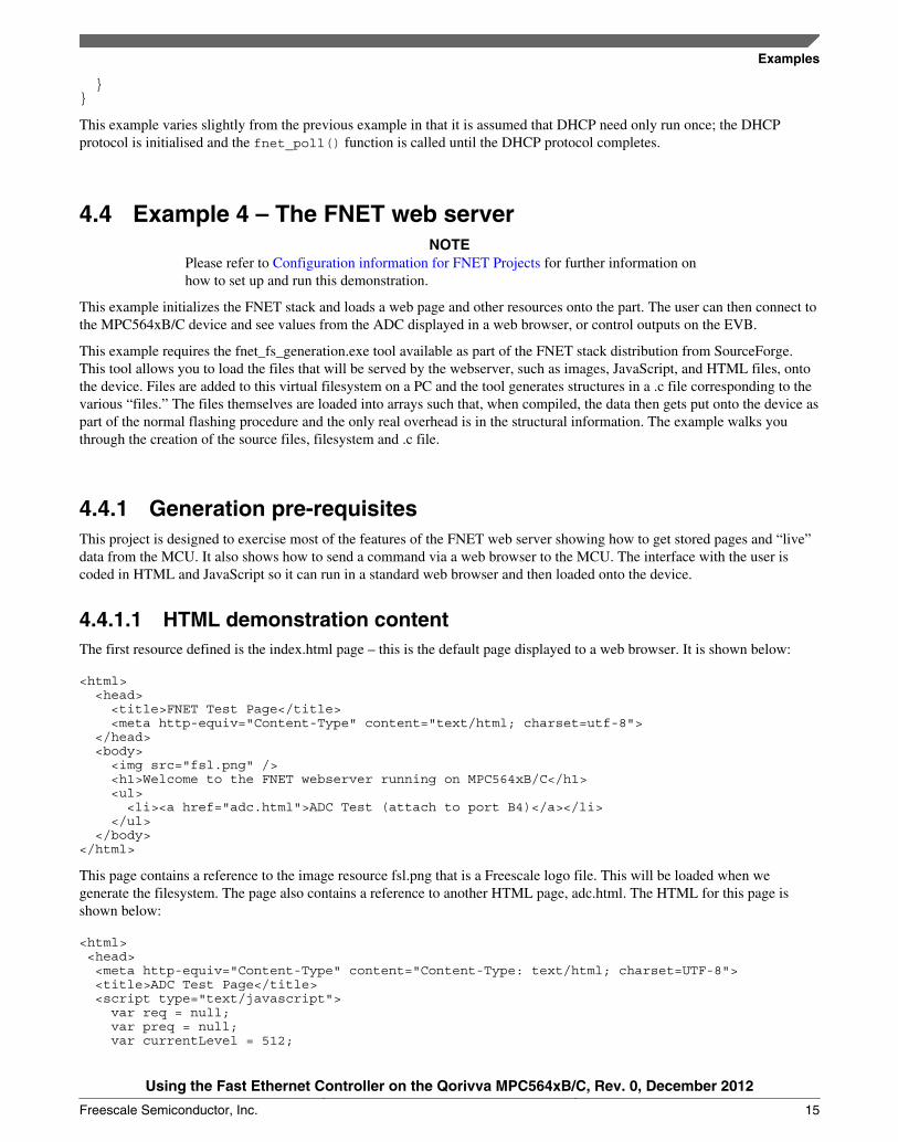
4.4.1.1 HTML demonstration contentThe first resource defined is the index.html page – this is the default page displayed to a web browser. It is shown below:
<html> <head> <title>FNET Test Page</title> <meta http-equiv="Content-Type" content="text/html; charset=utf-8"> </head> <body> <img src="fsl.png" /> <h1>Welcome to the FNET webserver running on MPC564xB/C</h1> <ul> <li><a href="adc.html">ADC Test (attach to port B4)</a></li> </ul> </body></html>
This page contains a reference to the image resource fsl.png that is a Freescale logo file. This will be loaded when wegenerate the filesystem. The page also contains a reference to another HTML page, adc.html. The HTML for this page isshown below:
<html> <head> <meta http-equiv="Content-Type" content="Content-Type: text/html; charset=UTF-8"> <title>ADC Test Page</title> <script type="text/javascript"> var req = null; var preq = null; var currentLevel = 512;
Examples
Using the Fast Ethernet Controller on the Qorivva MPC564xB/C, Rev. 0, December 2012
Freescale Semiconductor, Inc. 15

function xmlOpen(method, url, toSend, responseHandler) { if (req) { req.abort(); req.onreadystatechange = responseHandler; req.open(method, url, true); req.send(toSend); } }
function updateValue() { if (req.readyState == 4) { if (req.status == 200) { currentLevel = eval(req.responseText)[0].batt; updateGraphic(); setTimeout("getNewValue()",500); } } }
function getNewValue() { xmlOpen('GET', 'test.cgi', null, updateValue); }
function startXHR() { req = new XMLHttpRequest(); preq = new XMLHttpRequest(); getNewValue(); }
function updateGraphic() { var newwidth = (currentLevel * 631 / 1024) + 'px'; var batIcon = document.getElementById('batlevel'); if (currentLevel < 200) { batIcon.style.background = '#ffb2b2'; } else if (currentLevel < 600) { batIcon.style.background = '#e7b68c'; } else { batIcon.style.background = '#92cd9e'; } batIcon.style.width = newwidth; }
function requestFlash() { if (preq) { preq.open('POST', 'post.cgi?' + document.getElementById('flashval').value, true); preq.send(null); } } </script> </head> <body onload="javascript:startXHR();"> <img src="fsl.png" /> <h1>Welcome to the FNET webserver running on MPC564xB/C</h1> <a href="/">Back to homepage</a> <img src="batHighres.png" style="position: absolute; top: 200px; left: 50px; z-index: 10;" /> <div id="batlevel" style="position: absolute; top: 200px; left: 106px; width: 300px; height: 371px; background-color: #e7b68c;"></div> <div style="position: absolute; top: 600px; left: 106px; width: 300px;"> <input id="flashval" type="text" value="68"> <input type="submit" value="Flash" onclick="return requestFlash();"> </div> </body></html>
Examples
Using the Fast Ethernet Controller on the Qorivva MPC564xB/C, Rev. 0, December 2012
16 Freescale Semiconductor, Inc.

This page contains the Freescale logo again, but also the image of a battery (batHighres.png). Additionally, this page containsan onload JavaScript event that initiates a polling process. The startXHR() function creates to XMLHttpRequest objects thatcan be used for communication with the part without refreshing the whole web page — the instance req is used for GETrequests (the type of request normally used by a web browser to retrieve a resource) and the preq instance is used to POSTinformation to the MCU (the type of request normally used by a browser when submitting a form).
startXHR() calls the getNewValue() function that sends a request to the test.cgi resource on the MCU. Unlike the HTML andimage files, this resource is not added to the filesystem. Instead, test.cgi is registered as a handler and a function is executedto generate the content returned to the web browser. We will use this function to return live information from the MCU to thebrowser.
The MCU returns a JavaScript Object Notation (JSON) string as the response to test.cgi. This string is parsed by theupdateValue() JavaScript function. It extracts the response from the server, so the browser can handle the case where there isa failure, and if the XMLHttpRequest object is in readyState 4 (“request finished and response is ready”) and the HTTPresponse code is 200 (OK) then the JSON response is parsed and the batt value extracted. The function then updates thegraphic on the screen, using this to draw a variable-sized background for the battery image that appears to grow or shrink asthe value from the MCU gets larger or smaller. The final step for the updateValue() function is to request that thegetNewValue() function be called again after a further 500 ms. This value can be adjusted to increase or decrease thesampling rate. However, when attempting to run this too quickly, it’s possible to overflow the ring-buffer in the MCU (in thedefault configuration of only two buffers) and TCP timeouts will be observed. The number of entries in the ring-buffer can bechanged by setting the FNET_CFG_CPU_ETH_TX_BUFS_MAX and FNET_CFG_CPU_ETH_RX_BUFS_MAX variablesin fnet_user_config.h to a larger number; this allows a trade-off between performance and RAM usage.
The other example shown on this page is the input text box and button at the bottom of the page. Entering a GPIO number inthis box and clicking “Flash” will submit the GPIO number via an XMLHttpRequest POST request to the post.cgi handler.Like the test.cgi handler, this file does not exist but is rather hooked to a function that can extract the submitted value andwill then very quickly flash the GPIO line on the EVB.
4.4.1.2 Generating a file system for the MCUThe FNET FS Generation tool is used to create the file system for the device — this tool is installed by the FNET distributionfrom SourceForge. When started, you are presented with this screen.
Figure 6. Opening screen for FS generation tool
The file mentioned in the previous section can then be added to this image:
Examples
Using the Fast Ethernet Controller on the Qorivva MPC564xB/C, Rev. 0, December 2012
Freescale Semiconductor, Inc. 17

Figure 7. FS generation tool with files added
Next, an output file can be specified by clicking the folder icon with the right arrow next to the “Specify Image File” box.
Figure 8. FS generation tool with output file
At this stage, clicking “Generate” will create a file system file that can be used when programming the MCU.
4.4.2 Programming the MCUHaving coded and set up the high-level interactions for the application, the final step within this example is to add the filesystem, handlers, and startup code to the MCU. This example utilises the FNET HTTP server to handle communication withthe MPC564xB/C part. You must install the FNET for PPC installation and accept the license agreement in order to use thisexample. After installation, open the CodeWarrior project within Example4.zip and drag-and-drop the fnet_stack directoryinto the source tree.
Examples
Using the Fast Ethernet Controller on the Qorivva MPC564xB/C, Rev. 0, December 2012
18 Freescale Semiconductor, Inc.
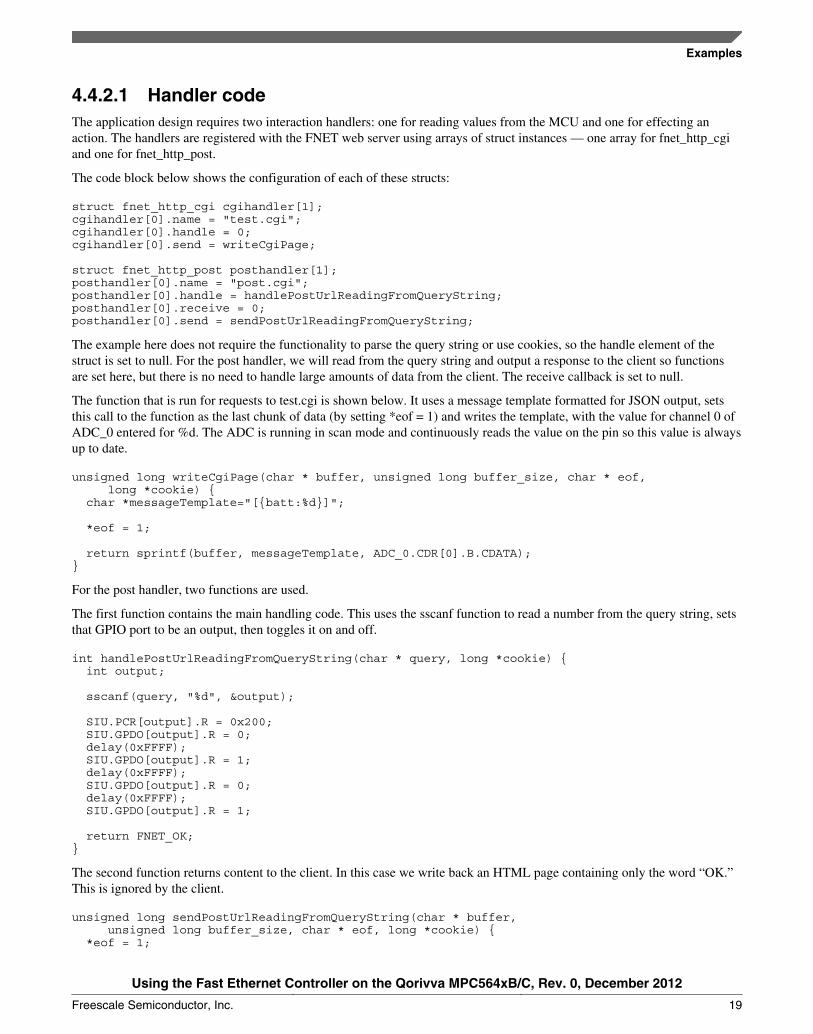
4.4.2.1 Handler codeThe application design requires two interaction handlers: one for reading values from the MCU and one for effecting anaction. The handlers are registered with the FNET web server using arrays of struct instances — one array for fnet_http_cgiand one for fnet_http_post.
The code block below shows the configuration of each of these structs:
struct fnet_http_cgi cgihandler[1];cgihandler[0].name = "test.cgi";cgihandler[0].handle = 0;cgihandler[0].send = writeCgiPage;
struct fnet_http_post posthandler[1];posthandler[0].name = "post.cgi";posthandler[0].handle = handlePostUrlReadingFromQueryString;posthandler[0].receive = 0;posthandler[0].send = sendPostUrlReadingFromQueryString;
The example here does not require the functionality to parse the query string or use cookies, so the handle element of thestruct is set to null. For the post handler, we will read from the query string and output a response to the client so functionsare set here, but there is no need to handle large amounts of data from the client. The receive callback is set to null.
The function that is run for requests to test.cgi is shown below. It uses a message template formatted for JSON output, setsthis call to the function as the last chunk of data (by setting *eof = 1) and writes the template, with the value for channel 0 ofADC_0 entered for %d. The ADC is running in scan mode and continuously reads the value on the pin so this value is alwaysup to date.
unsigned long writeCgiPage(char * buffer, unsigned long buffer_size, char * eof, long *cookie) { char *messageTemplate="[{batt:%d}]";
*eof = 1;
return sprintf(buffer, messageTemplate, ADC_0.CDR[0].B.CDATA);}
For the post handler, two functions are used.
The first function contains the main handling code. This uses the sscanf function to read a number from the query string, setsthat GPIO port to be an output, then toggles it on and off.
int handlePostUrlReadingFromQueryString(char * query, long *cookie) { int output;
sscanf(query, "%d", &output);
SIU.PCR[output].R = 0x200; SIU.GPDO[output].R = 0; delay(0xFFFF); SIU.GPDO[output].R = 1; delay(0xFFFF); SIU.GPDO[output].R = 0; delay(0xFFFF); SIU.GPDO[output].R = 1;
return FNET_OK;}
The second function returns content to the client. In this case we write back an HTML page containing only the word “OK.”This is ignored by the client.
unsigned long sendPostUrlReadingFromQueryString(char * buffer, unsigned long buffer_size, char * eof, long *cookie) { *eof = 1;
Examples
Using the Fast Ethernet Controller on the Qorivva MPC564xB/C, Rev. 0, December 2012
Freescale Semiconductor, Inc. 19
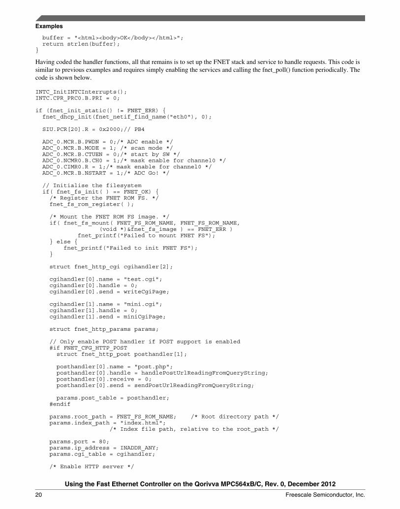
buffer = "<html><body>OK</body></html>"; return strlen(buffer);}
Having coded the handler functions, all that remains is to set up the FNET stack and service to handle requests. This code issimilar to previous examples and requires simply enabling the services and calling the fnet_poll() function periodically. Thecode is shown below.
INTC_InitINTCInterrupts();INTC.CPR_PRC0.B.PRI = 0;
if (fnet_init_static() != FNET_ERR) { fnet_dhcp_init(fnet_netif_find_name("eth0"), 0);
SIU.PCR[20].R = 0x2000;// PB4
ADC_0.MCR.B.PWDN = 0;/* ADC enable */ ADC_0.MCR.B.MODE = 1; /* scan mode */ ADC_0.MCR.B.CTUEN = 0;/* start by SW */ ADC_0.NCMR0.B.CH0 = 1;/* mask enable for channel0 */ ADC_0.CIMR0.R = 1;/* mask enable for channel0 */ ADC_0.MCR.B.NSTART = 1;/* ADC Go! */
// Initialise the filesystem if( fnet_fs_init( ) == FNET_OK) { /* Register the FNET ROM FS. */ fnet_fs_rom_register( ); /* Mount the FNET ROM FS image. */ if( fnet_fs_mount( FNET_FS_ROM_NAME, FNET_FS_ROM_NAME, (void *)&fnet_fs_image ) == FNET_ERR ) fnet_printf("Failed to mount FNET FS"); } else { fnet_printf("Failed to init FNET FS"); }
struct fnet_http_cgi cgihandler[2];
cgihandler[0].name = "test.cgi"; cgihandler[0].handle = 0; cgihandler[0].send = writeCgiPage;
cgihandler[1].name = "mini.cgi"; cgihandler[1].handle = 0; cgihandler[1].send = miniCgiPage;
struct fnet_http_params params;
// Only enable POST handler if POST support is enabled #if FNET_CFG_HTTP_POST struct fnet_http_post posthandler[1];
posthandler[0].name = "post.php"; posthandler[0].handle = handlePostUrlReadingFromQueryString; posthandler[0].receive = 0; posthandler[0].send = sendPostUrlReadingFromQueryString;
params.post_table = posthandler; #endif params.root_path = FNET_FS_ROM_NAME; /* Root directory path */ params.index_path = "index.html"; /* Index file path, relative to the root_path */
params.port = 80; params.ip_address = INADDR_ANY; params.cgi_table = cgihandler;
/* Enable HTTP server */
Examples
Using the Fast Ethernet Controller on the Qorivva MPC564xB/C, Rev. 0, December 2012
20 Freescale Semiconductor, Inc.

fnet_http_desc_t http_desc = fnet_http_init(¶ms); fnet_printf("HTTP Inited"); while(1) { fnet_poll(); } }}
When this program is executed and the device is hooked up to a router or infrastructure providing DHCP services, the partwill obtain an IP address. Entering this address in a web browser on an accessible network will give the following page.
Figure 9. Device home page
Clicking on the ADC test link presents this page:
Examples
Using the Fast Ethernet Controller on the Qorivva MPC564xB/C, Rev. 0, December 2012
Freescale Semiconductor, Inc. 21

Figure 10. Device page showing read and write interaction
Using the same connection as Example 1 — connecting the variable potentiometer output to port PB4 — should allow thebattery gauge to be changed by altering the potentiometer. Clicking the “Flash” button will flash LED1 on the EVB —LED1–LED4 can be selected using values 68–71.
Appendix A Configuration information for FNET ProjectsExamples 2, 3, and 4 in this application note use the FNET project with PPC support provided in the supporting material.Further information on the operation of the FNET library and API documentation can be found at http://fnet.sourceforge.net.This FNET for PPC library supports Freescale CodeWarrior.
The only feature that has not been implemented in the PPC port of FNET is the on-chip flash write driver. Freescale providesflash drivers for these parts on Freescale.com.
To use the FNET library, simply create a new project using the stationery for the MPC564xB/C within CodeWarrior. Afterthe project has been created, the following line has to be added to the bottom of the CodeWarrior Linker Control File (LCF)to allow FNET to handle interrupts:
__VECTOR_RAM = ADDR(.__uninitialized_intc_handlertable);
Once this step has been completed, drag and drop the fnet_stack folder into the CodeWarrior project. CodeWarrior willimport this code, making the code available for use. The final step is to configure required features within thefnet_user_config.h file.
It is recommended that V2.9 or later of CodeWarrior be used, because an error in the MPC564xB/C stationery in earlierversions prevents the stack from starting correctly. Alternatively, the EXCEP_InitExceptionHandlers function in theexceptions.c file can be patched by changing references to R2 to R3.
The problem in older stationery arises because the CodeWarrior compiler uses the R2 core register as pointer to the smalldata area. By changing this value in the EXCEP_InitExceptionHandlers function, const data held in flash memory is not readcorrectly. R3 is not used at this point during startup and can be safely used.
Using the Fast Ethernet Controller on the Qorivva MPC564xB/C, Rev. 0, December 2012
22 Freescale Semiconductor, Inc.

Appendix B A Java UDP Client for Example 2This appendix contains a sample console-based Java application that can be used to interact with a microcontroller using theUDP-based protocol example in Example 2.
import java.io.BufferedReader;import java.io.ByteArrayOutputStream;import java.io.IOException;import java.io.InputStreamReader;import java.net.DatagramPacket;import java.net.DatagramSocket;import java.net.InetAddress;
public class UdpControl { public static void main(String[] args) throws IOException { String temp; InetAddress remoteIp; int remotePort;
BufferedReader r = new BufferedReader(new InputStreamReader(System.in));
System.out.println(" Ethernet UDP Demonstration"); System.out.println("------------------------------\n");
// Read necessary parameters - destination IP and port System.out.print("Enter remote IP to sent to: "); temp = r.readLine(); remoteIp = InetAddress.getByName(temp);
System.out.print("Enter remote port to send to: "); temp = r.readLine(); remotePort = Integer.parseInt(temp);
System.out.println("Entering control loop - enter port -1 to quit\n");
DatagramSocket socket = new DatagramSocket();
// Main loop - get a port number and 0 for OFF, 1 for ON while(true) { int portNum, task; ByteArrayOutputStream bos = new ByteArrayOutputStream(); System.out.print(" Enter port: "); try { portNum = Integer.parseInt(r.readLine()); } catch (NumberFormatException e) { System.out.println("Invalid entry"); continue; }
if (portNum == -1) break;
System.out.print("Enter state (0-off, 1-on): ");
try { task = Integer.parseInt(r.readLine()); } catch (NumberFormatException e) { System.out.println("Invalid entry"); continue; }
// Prepare bytes of 4byte integers for packet bos.write(portNum >> 24); bos.write(portNum >> 16); bos.write(portNum >> 8); bos.write(portNum); bos.write(task >> 24); bos.write(task >> 16); bos.write(task >> 8); bos.write(task);
Using the Fast Ethernet Controller on the Qorivva MPC564xB/C, Rev. 0, December 2012
Freescale Semiconductor, Inc. 23

// Send packet DatagramPacket packetout = new DatagramPacket(bos.toByteArray(), bos.size(), remoteIp, remotePort); socket.send(packetout);
// Get response byte[] rcvdData = new byte[1024]; DatagramPacket rcvdPacket = new DatagramPacket(rcvdData, rcvdData.length); socket.receive(rcvdPacket);
// Print response from device System.out.println("Received: " + new String(rcvdData, 0, rcvdPacket.getLength() - 1)); }
socket.close(); }}
Using the Fast Ethernet Controller on the Qorivva MPC564xB/C, Rev. 0, December 2012
24 Freescale Semiconductor, Inc.

How to Reach Us:
Home Page:www.freescale.com
Web Support:http://www.freescale.com/support
USA/Europe or Locations Not Listed:Freescale SemiconductorTechnical Information Center, EL5162100 East Elliot RoadTempe, Arizona 85284+1-800-521-6274 or +1-480-768-2130www.freescale.com/support
Europe, Middle East, and Africa:Freescale Halbleiter Deutschland GmbHTechnical Information CenterSchatzbogen 781829 Muenchen, Germany+44 1296 380 456 (English)+46 8 52200080 (English)+49 89 92103 559 (German)+33 1 69 35 48 48 (French)www.freescale.com/support
Japan:Freescale Semiconductor Japan Ltd.HeadquartersARCO Tower 15F1-8-1, Shimo-Meguro, Meguro-ku,Tokyo 153-0064Japan0120 191014 or +81 3 5437 [email protected]
Asia/Pacific:Freescale Semiconductor China Ltd.Exchange Building 23FNo. 118 Jianguo RoadChaoyang DistrictBeijing 100022China+86 10 5879 [email protected]
Document Number: AN4577Rev. 0, December 2012
Information in this document is provided solely to enable system and softwareimplementers to use Freescale Semiconductors products. There are no express or impliedcopyright licenses granted hereunder to design or fabricate any integrated circuits orintegrated circuits based on the information in this document.
Freescale Semiconductor reserves the right to make changes without further notice to anyproducts herein. Freescale Semiconductor makes no warranty, representation, orguarantee regarding the suitability of its products for any particular purpose, nor doesFreescale Semiconductor assume any liability arising out of the application or use of anyproduct or circuit, and specifically disclaims any liability, including without limitationconsequential or incidental damages. "Typical" parameters that may be provided inFreescale Semiconductor data sheets and/or specifications can and do vary in differentapplications and actual performance may vary over time. All operating parameters,including "Typicals", must be validated for each customer application by customer'stechnical experts. Freescale Semiconductor does not convey any license under its patentrights nor the rights of others. Freescale Semiconductor products are not designed,intended, or authorized for use as components in systems intended for surgical implantinto the body, or other applications intended to support or sustain life, or for any otherapplication in which failure of the Freescale Semiconductor product could create asituation where personal injury or death may occur. Should Buyer purchase or useFreescale Semiconductor products for any such unintended or unauthorized application,Buyer shall indemnify Freescale Semiconductor and its officers, employees, subsidiaries,affiliates, and distributors harmless against all claims, costs, damages, and expenses, andreasonable attorney fees arising out of, directly or indirectly, any claim of personal injuryor death associated with such unintended or unauthorized use, even if such claims allegesthat Freescale Semiconductor was negligent regarding the design or manufacture ofthe part.
RoHS-compliant and/or Pb-free versions of Freescale products have the functionality andelectrical characteristics as their non-RoHS-complaint and/or non-Pb-free counterparts.For further information, see http://www.freescale.com or contact your Freescalesales representative.
For information on Freescale's Environmental Products program, go tohttp://www.freescale.com/epp.
Freescale™ and the Freescale logo are trademarks of Freescale Semiconductor, Inc.All other product or service names are the property of their respective owners.
© 2012 Freescale Semiconductor, Inc.


