Embed Size (px)
Citation preview
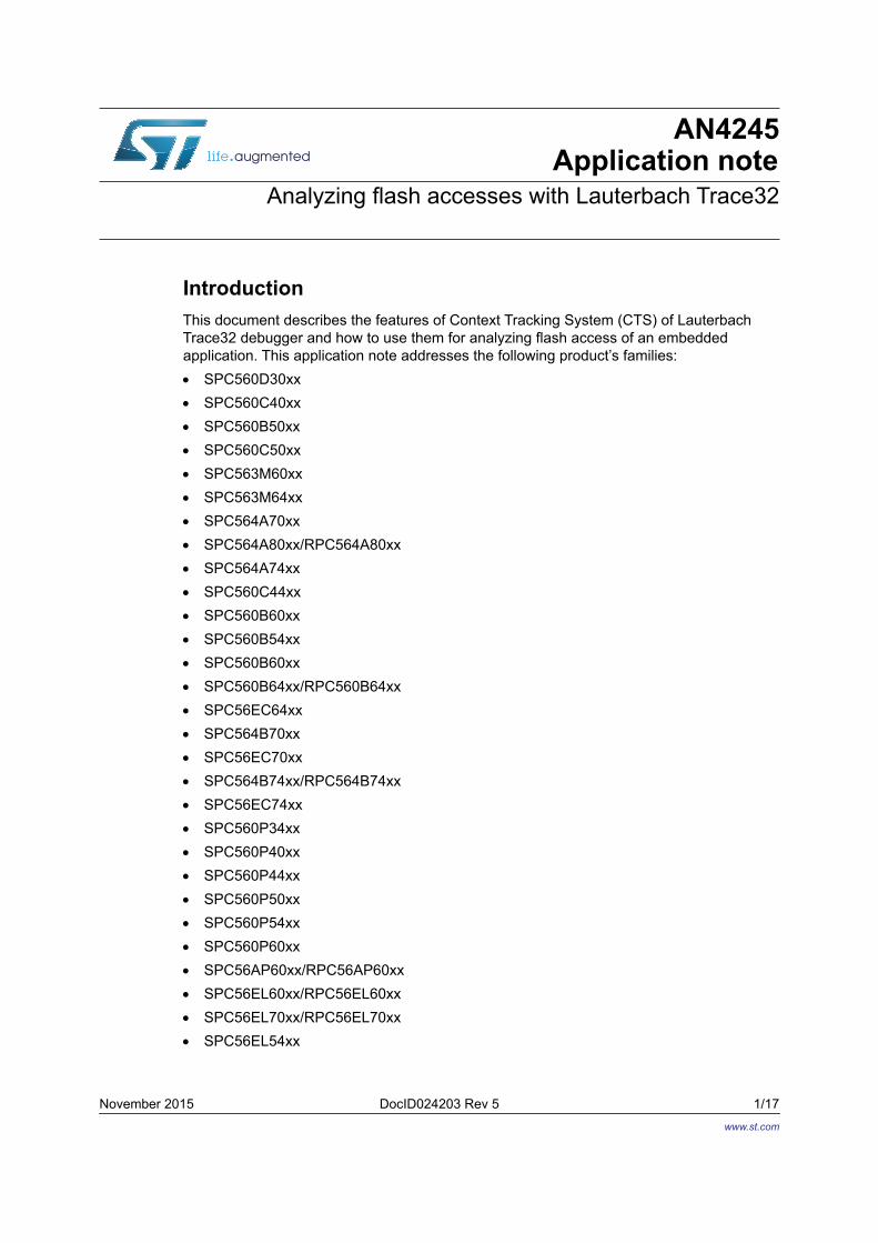
November 2015 DocID024203 Rev 5 1/17
AN4245Application note
Analyzing flash accesses with Lauterbach Trace32
IntroductionThis document describes the features of Context Tracking System (CTS) of Lauterbach Trace32 debugger and how to use them for analyzing flash access of an embedded application. This application note addresses the following product’s families: SPC560D30xx SPC560C40xx SPC560B50xx SPC560C50xx SPC563M60xx SPC563M64xx SPC564A70xx SPC564A80xx/RPC564A80xx SPC564A74xx SPC560C44xx SPC560B60xx SPC560B54xx SPC560B60xx SPC560B64xx/RPC560B64xx SPC56EC64xx SPC564B70xx SPC56EC70xx SPC564B74xx/RPC564B74xx SPC56EC74xx SPC560P34xx SPC560P40xx SPC560P44xx SPC560P50xx SPC560P54xx SPC560P60xx SPC56AP60xx/RPC56AP60xx SPC56EL60xx/RPC56EL60xx SPC56EL70xx/RPC56EL70xx SPC56EL54xx
www.st.com

Contents AN4245
2/17 DocID024203 Rev 5
Contents
1 Overview . . . . . . . . . . . . . . . . . . . . . . . . . . . . . . . . . . . . . . . . . . . . . . . . . . 51.1 PFLASH Controller . . . . . . . . . . . . . . . . . . . . . . . . . . . . . . . . . . . . . . . . . . . 5
1.2 Branch Unit . . . . . . . . . . . . . . . . . . . . . . . . . . . . . . . . . . . . . . . . . . . . . . . . . 6
1.3 CTS model implementation . . . . . . . . . . . . . . . . . . . . . . . . . . . . . . . . . . . . 6
2 Getting started with CTS . . . . . . . . . . . . . . . . . . . . . . . . . . . . . . . . . . . . . 82.1 Running CTS . . . . . . . . . . . . . . . . . . . . . . . . . . . . . . . . . . . . . . . . . . . . . . . 8
2.2 Configuring BTB . . . . . . . . . . . . . . . . . . . . . . . . . . . . . . . . . . . . . . . . . . . 10
2.3 Running the analysis . . . . . . . . . . . . . . . . . . . . . . . . . . . . . . . . . . . . . . . . 10
2.4 Lauterbach script example . . . . . . . . . . . . . . . . . . . . . . . . . . . . . . . . . . . . 10
2.5 How to check queue and FLASH buffers step-by-step . . . . . . . . . . . . . . 11
2.6 Viewing analysis results . . . . . . . . . . . . . . . . . . . . . . . . . . . . . . . . . . . . . . 11
2.7 Viewing results for BTB . . . . . . . . . . . . . . . . . . . . . . . . . . . . . . . . . . . . . . 12
2.8 Sample use case . . . . . . . . . . . . . . . . . . . . . . . . . . . . . . . . . . . . . . . . . . . 13
3 CTS Command reference . . . . . . . . . . . . . . . . . . . . . . . . . . . . . . . . . . . . 143.1 CTS.Cache.Cycles . . . . . . . . . . . . . . . . . . . . . . . . . . . . . . . . . . . . . . . . . . 14
3.2 CTS. Cache.L1Architecture . . . . . . . . . . . . . . . . . . . . . . . . . . . . . . . . . . . 14
3.3 CTS.Cache.View . . . . . . . . . . . . . . . . . . . . . . . . . . . . . . . . . . . . . . . . . . . 14
3.4 CTS. Cache.ViewBPU . . . . . . . . . . . . . . . . . . . . . . . . . . . . . . . . . . . . . . . 14
3.5 CTS.Mode . . . . . . . . . . . . . . . . . . . . . . . . . . . . . . . . . . . . . . . . . . . . . . . . 14
3.6 CTS.Process . . . . . . . . . . . . . . . . . . . . . . . . . . . . . . . . . . . . . . . . . . . . . . 14
3.7 Map.Volatile . . . . . . . . . . . . . . . . . . . . . . . . . . . . . . . . . . . . . . . . . . . . . . . 15
3.8 Map.DenyAccess . . . . . . . . . . . . . . . . . . . . . . . . . . . . . . . . . . . . . . . . . . . 15
4 Revision history . . . . . . . . . . . . . . . . . . . . . . . . . . . . . . . . . . . . . . . . . . . 16

DocID024203 Rev 5 3/17
AN4245 List of tables
3
List of tables
Table 1. Document revision history. . . . . . . . . . . . . . . . . . . . . . . . . . . . . . . . . . . . . . . . . . . . . . . . . . 16

List of figures AN4245
4/17 DocID024203 Rev 5
List of figures
Figure 1. Flash memory architecture for SPC56xx/RPC56xx devices. . . . . . . . . . . . . . . . . . . . . . . . . 5Figure 2. Zen instruction buffers . . . . . . . . . . . . . . . . . . . . . . . . . . . . . . . . . . . . . . . . . . . . . . . . . . . . . 6Figure 3. Run CTS . . . . . . . . . . . . . . . . . . . . . . . . . . . . . . . . . . . . . . . . . . . . . . . . . . . . . . . . . . . . . . . . 8Figure 4. CTS Cache Configuration. . . . . . . . . . . . . . . . . . . . . . . . . . . . . . . . . . . . . . . . . . . . . . . . . . . 9Figure 5. CTS Dump B0. . . . . . . . . . . . . . . . . . . . . . . . . . . . . . . . . . . . . . . . . . . . . . . . . . . . . . . . . . . 11Figure 6. CTS cache address list . . . . . . . . . . . . . . . . . . . . . . . . . . . . . . . . . . . . . . . . . . . . . . . . . . . . 11Figure 7. CTS CACHE View . . . . . . . . . . . . . . . . . . . . . . . . . . . . . . . . . . . . . . . . . . . . . . . . . . . . . . . 12Figure 8. CTS CACHE View BPU . . . . . . . . . . . . . . . . . . . . . . . . . . . . . . . . . . . . . . . . . . . . . . . . . . . 12

DocID024203 Rev 5 5/17
AN4245 Overview
16
1 Overview
1.1 PFLASH ControllerSPC56xx/RPC56xx MCU family flash memory comprises a platform Flash controller interface and two Flash memory arrays.
Figure 1. Flash memory architecture for SPC56xx/RPC56xx devices
The PFLASH Controller acts as an interface between the platform’s system bus (AHB Crossbar) and up to two integrated flash memory arrays from STMicroelectronics (low-cost 90-nm for SPC56xx/RPC56xx devices and low-cost 55-nm for SPC57xx devices).For SPC57xx devices both banks, code and data, have four buffers.
The PFLASH logic associated with the code flash bank contains a four-entry “page” buffer, each entry containing 128 bits of data (1 flash page) plus an associated controller which prefetches sequential lines of data from the flash array into the buffer, while the controller logic associated with the data flash bank only supports one 128-bit register which serves as a temporary page holding register and does not support any prefetching. Prefetch buffer hits from the code flash bank support zero-wait AHB data phase responses. AHB read requests which miss the buffers generate the needed flash array access and are forwarded to the AHB upon completion, typically incurring two wait-states at an operating frequency of 60 - 64 MHz.

Overview AN4245
6/17 DocID024203 Rev 5
1.2 Branch UnitTo resolve branch instructions and accelerate execution of branch instructions, SPC560x/RPC560x devices integrate a dynamic branch prediction mechanism using a 1-entry branch target buffer (BTB), a fully associative address cache of branch target addresses.
Conditional branches which are not taken execute in a single clock. Branches with successful target prefetching have an effective execution time of one clock. All other taken branches have an execution time of two clocks.
Figure 2. Zen instruction buffers
1.3 CTS model implementationThe Lauterbach Trace32 allows, through an integrated tool, to implement features suited for Context Tracking System (CTS). The implemented CTS algorithms allow the context of the target system to be reconstructed for each single record sampled to the trace buffer. Context of the target system means here the contents of the CPU registers, the memories, the caches and TLBs (Translation Lookaside Buffers).
The main application for CTS is the so-called trace-based debugging. Trace-based debugging allows rerunning the program and data flow sampled to the trace buffer on the Trace32 screen.
Based on the CTS technology, Trace32 offers the possibility to perform a cache analysis.
The cache analysis can be used to emulate and to analyze the flash access.
To perform a correct analysis of the flash access the CTS.CACHE model will be used to emulate the prefetch buffer strategy implemented in the PFLASH controller and the BTB of the real device.
It is necessary execute a CACHE configuration to configure the prefetch buffer, indicating the number of the buffers and the width for the instructions and data buffers.
The prefetch is triggered by an instruction fetch read access and we can distinguish three different configurations: No buffering enabled at all; Buffering enabled, the referenced line is prefetched on a buffer miss, that is, prefetch
on miss; The referenced line is prefetched on a buffer miss, or the next sequential page is
prefetched on a buffer hit (if not already present), that is, prefetch on miss or hit.

DocID024203 Rev 5 7/17
AN4245 Overview
16
When prefetching on hit or miss for block 0 is enabled it is assumed that there will be an access also to the following flash buffer.
The "victims" column in the view report shows the number of prefetches done by the flash controller (this number is NOT included in the "misses" column). Using this column it is possible to measure and analyze the access to the flash.
The analysis does not take care about the timing.
The "timing" related behavior cannot be reconstructed "reliable". It is assumed that the number shows what would be the "worst case" - when the core is "slow enough" to let the prefetch happen.

Getting started with CTS AN4245
8/17 DocID024203 Rev 5
2 Getting started with CTS
2.1 Running CTS1. Run CTS
Figure 3. Run CTS
2. Select cache analysis mode for CTS using CTS.Mode CACHE.3. Select the CACHE configuration.

DocID024203 Rev 5 9/17
AN4245 Getting started with CTS
16
Figure 4. CTS Cache Configuration
4. Specify the way hit & misses should be measured with CTS.Cache.Cycles NonSequential.
5. It is not recommended to change the configuration. The user should just verify that it matches their integrated flash memory chip:– The number of buffers with CTS.Cache.ways B0 x, where x is the number of
buffers reserved for instructions cache;– The length of a line with CTS.Cache.Width B0 x, where x is the width in bytes;– The number of buffers with CTS.Cache.ways B1 x, where x is the number of
reserved buffers for data cache;– Define the length of a line with CTS.Cache.Width B1 x, where x is the width in
bytes.6. It is necessary to configure the registers of the Prefetch buffer of the flash.
E.g. for SPC570Sxx device a configuration could be (using Lauterbach command) d.s 0xfc030000%l 0x55 0x55, the Platform Flash Configuration Register 1 (PFCR1) and Platform Flash Configuration Register 2 (PFCR2) are configured:– PFCR1.P0_BFEN = 1 the line read buffers are enabled to satisfy read requests on
hits. Buffer valid bits may be set when the buffers are successfully filled.– PFCR1.P0_PFLIM = 10 the referenced line is prefetched on a buffer miss, or the
next sequential line is prefetched on a buffer hit (if not already present), that is, prefetch on miss or hit.
– PFCR1.P0_IPFEN = 1 prefetching may be triggered by any instruction read access.
– PFCR1.P0_DPFEN = 1 prefetching may be triggered by any data read access.– PFCR2.P1_BFEN = 1 the line read buffers are enabled to satisfy read requests on
hits. Buffer valid bits may be set when the buffers are successfully filled.

Getting started with CTS AN4245
10/17 DocID024203 Rev 5
– PFCR2.P1_PFLIM = 10 the referenced line is prefetched on a buffer miss, or the next sequential line is prefetched on a buffer hit (if not already present), that is, prefetch on miss or hit.
– PFCR2.P1_IPFEN = 1 prefetching may be triggered by any instruction read access.
– PFCR2.P1_DPFEN = 1 prefetching may be triggered by any data read access.
2.2 Configuring BTB In general the FLASH analysis tries to care about all settings from the target and considers the values in the control registers. This applies also to the branch predication unit of the core.
2.3 Running the analysisIn order to analyze a code:1. Trace the interesting part of the code;2. Select cache analysis mode for CTS using CTS.Mode Cache;3. Process the trace with CTS.Process;4. Display results with the command CTS.Cache.View.
2.4 Lauterbach script exampleThe following Lauterbach script could be used to configure the CTS of a SPC570Sxx device:
sys.cpu SPC570S50sys.ua.load analyzer; analyzer parameter is a file (analyzer.ad) that is the trace buffer contents saved (Analyzer.SAVE file) d.s 0xfc030000%l 0x55 0x55cts.cache.l1a unifiedsplitcts.cache.cy nonsequentialcts.mode cacheenddo

DocID024203 Rev 5 11/17
AN4245 Getting started with CTS
16
2.5 How to check queue and FLASH buffers step-by-step You can check queue and FLASH buffers issuing the following commands:
CACHE.DUMP B0
Figure 5. CTS Dump B0
2.6 Viewing analysis resultsTo display the number of accesses for each flash row use the following command:cts.cache.listaddress B0I 0--0xfffff 0x100.
The result of the command is shown in Figure 6.
Figure 6. CTS cache address list
where:
Misses = number of flash accesses, not including prefetch controller
Victims = number of flash accesses including the prefetch controller

Getting started with CTS AN4245
12/17 DocID024203 Rev 5
In the model with emulated prefetch buffer the "victims" column shows the number of prefetches done by the flash controller (this number is NOT included in the "misses" column).
A general view of the access to the flash can be obtained by the trace32 command:
CTS.CACHE.View
Figure 7. CTS CACHE View
2.7 Viewing results for BTBTo display a report of BTB hit rates, use the command CTS.CACHE.ViewBPU
Figure 8. CTS CACHE View BPU
where BTAC = Dynamic branch prediction.
DocID024203 Rev 5 13/17
AN4245 Getting started with CTS
16
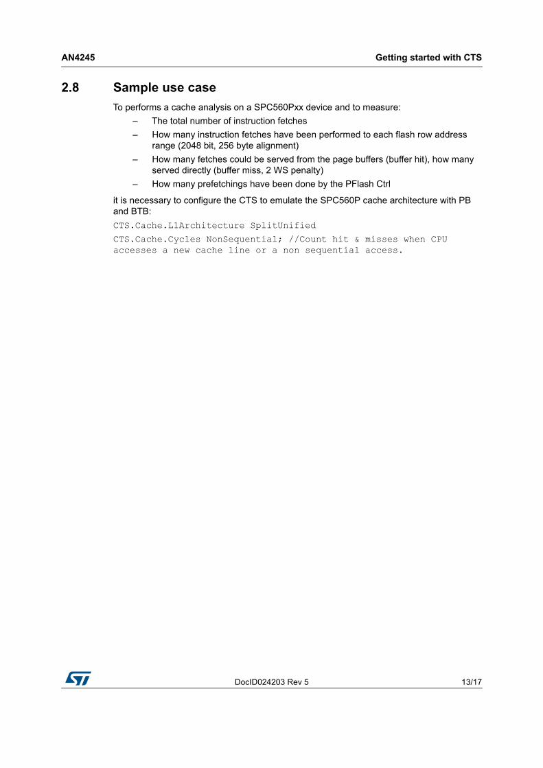
2.8 Sample use caseTo performs a cache analysis on a SPC560Pxx device and to measure:
– The total number of instruction fetches– How many instruction fetches have been performed to each flash row address
range (2048 bit, 256 byte alignment)– How many fetches could be served from the page buffers (buffer hit), how many
served directly (buffer miss, 2 WS penalty)– How many prefetchings have been done by the PFlash Ctrl
it is necessary to configure the CTS to emulate the SPC560P cache architecture with PB and BTB:CTS.Cache.L1Architecture SplitUnifiedCTS.Cache.Cycles NonSequential; //Count hit & misses when CPU accesses a new cache line or a non sequential access.
CTS Command reference AN4245
14/17 DocID024203 Rev 5
3 CTS Command reference
This paragraph describes a set of Trace32 commands useful for analyzing flash accesses on SPC560x/RPC560x MCU family.
3.1 CTS.Cache.CyclesThe CTS.Cache.Cycles defines which method is used to count the cache hit/cache miss rate:
– Core - the hit or miss counter is incremented on every core cycle.– Bus - the hit or miss counter is incremented on every bus cycle.– NonSequential - the hit or miss counter is only incremented if the CPU accesses a
new cache line or performs a non-sequential access.
3.2 CTS. Cache.L1Architecture CTS. Cache.L1Architecture defines the architecture of the level 1 cache (Harvard or unified).
For SPC560Pxx use UnifiedSplitt: The L1 cache is a unified cache that means the same cache is used for instruction fetches and data loads/stores.
TRACE32 splits the unified cache in an instruction and data cache for the cache analysis. The splitting is based on the cycle type (e.g. read/write/ptrace/exec).
3.3 CTS.Cache.ViewCTS.Cache.View displays the results of the cache analysis. CTS.Mode CACHE has to be selected before any calculation can be started.
3.4 CTS. Cache.ViewBPUCTS. Cache.ViewBPU displays results of branch prediction unit hit and misses.
3.5 CTS.ModeCTS.Mode defines the analysis mode used by CTS. For cache analysis it should be set to CACHE in order to reconstructs the contents of caches and Translation Lookaside Buffers (TLBs).
3.6 CTS.ProcessCTS.Process starts the analysis of trace data.

DocID024203 Rev 5 15/17
AN4245 CTS Command reference
16
3.7 Map.VolatileThe Map.Volatile command allows to define a memory range that is changed not only by the processor core, as peripherals, dual-ported memory etc. It is a bit similar to the "C" volatile keyword.
It means that changes to this memory range are not all sampled to the trace buffer. CTS will then not attempt to reconstruct the value there and also will not try to use the “current memory” content.
Due to this attribute this memory range cannot be used for CTS.
3.8 Map.DenyAccessThe TRACE32 software can't access the specified target address range. This command can be used when accesses by the development tool to specific target memory address ranges cause problems (i.e. “emulation debug port fail”, “emulator berr error”).
The address ranges that can't be accessed by the TRACE32 software can be displayed by the MAP.List command.

Revision history AN4245
16/17 DocID024203 Rev 5
4 Revision history
Table 1. Document revision historyDate Revision Changes
20-Mar-2013 1 Initial release.
10-Jul-2013 2 Updated entire document.
22-Jul-2013 3 Modified Section 2.6: Viewing analysis results.
17-Sep-2013 4 Updated Disclaimer.
03-Nov-2015 5 Robust root part numbers added.

DocID024203 Rev 5 17/17
AN4245
17
IMPORTANT NOTICE – PLEASE READ CAREFULLY
STMicroelectronics NV and its subsidiaries (“ST”) reserve the right to make changes, corrections, enhancements, modifications, and improvements to ST products and/or to this document at any time without notice. Purchasers should obtain the latest relevant information on ST products before placing orders. ST products are sold pursuant to ST’s terms and conditions of sale in place at the time of order acknowledgement.
Purchasers are solely responsible for the choice, selection, and use of ST products and ST assumes no liability for application assistance or the design of Purchasers’ products.
No license, express or implied, to any intellectual property right is granted by ST herein.
Resale of ST products with provisions different from the information set forth herein shall void any warranty granted by ST for such product.
ST and the ST logo are trademarks of ST. All other product or service names are the property of their respective owners.
Information in this document supersedes and replaces information previously supplied in any prior versions of this document.
© 2015 STMicroelectronics – All rights reserved