Embed Size (px)
Citation preview

© Freescale Semiconductor, Inc., 2009-2010. All rights reserved.
Freescale Semiconductor Document Number: AN3859
Application Note
Adding Device(s) to CodeWarrior Flash Programmer for Microcontrollers V10.0
1. Introduction This document explains how to use the Flash Tool Kit to support additional flash devices on the Flash Programmer for CodeWarrior Development Studio for Microcontrollers V10.0 by creating new programming algorithms and support files.. This application note applies only to the external flash devices used with ColdFire V2/V3/V4 processors. This document includes these topics.
• Create a flash device XML configuration file
• Create new target task
• Create external flash alogrithm
• Flash programmer examples
• Create new flash utility
• Flash utility examples
• Troubleshooting flash programmer
2. Preliminary Background Before you program or erase any flash device, ensure that the CPU can access the flash device. For example, you might need a different debug setup that requires
Contents 1. Introduction .............................................................. 12. Preliminary Background ......................................... 13. Flash Tool Kit (FTK) Overview ................................ 24. Creating Flash Device XML Configuration File ..... 25. Create New Target Task ........................................ 136. Creating External Flash Algorithm ....................... 247. Flash Programming Examples ............................. 448. Create New Flash Utility ........................................ 559. Flash Utility Examples ........................................... 6210. Troubleshooting Flash Programmer .................... 68

Flash Tool Kit (FTK) Overview
Adding Device(s) to CodeWarrior Flash Programmer for Microcontrollers V10.0 2 Freescale Semiconductor
modifications in the debugger configuration file. Consider the following before you begin:
• Read the flash device ID to verify the correct connection and programmability. Refer section Troubleshooting Flash Programmer for details. NOTE Many manufacturers use the same flash device algorithms, so it is likely that flashes can
be programmed using the algorithms included with the CodeWarrior software. In addition, many manufacturers produce devices compatible with those of Intel, Advanced Micro Devices (AMD), or STMicroelectronics (ST).
• Check whether the new flash device can be programmed with the same algorithms that ST uses.
• Refer to the section Select Flash Programming Algorithm to determine if the flash device is programmable with an algorithm already included with the CodeWarrior software.
• Follow the steps in section Creating External Flash Algorithm if the flash device cannot be programmed with an existing algorithm.
3. Flash Tool Kit (FTK) Overview Adding a new flash device support requires few new files, including:
• xml configuration file for the new device, which describes the organization,
• xml configuration file for the board, which specifies the flash it must use and where is the RAM memory located, and
• flash device algorithm if none of the existing algorithms are compatible.
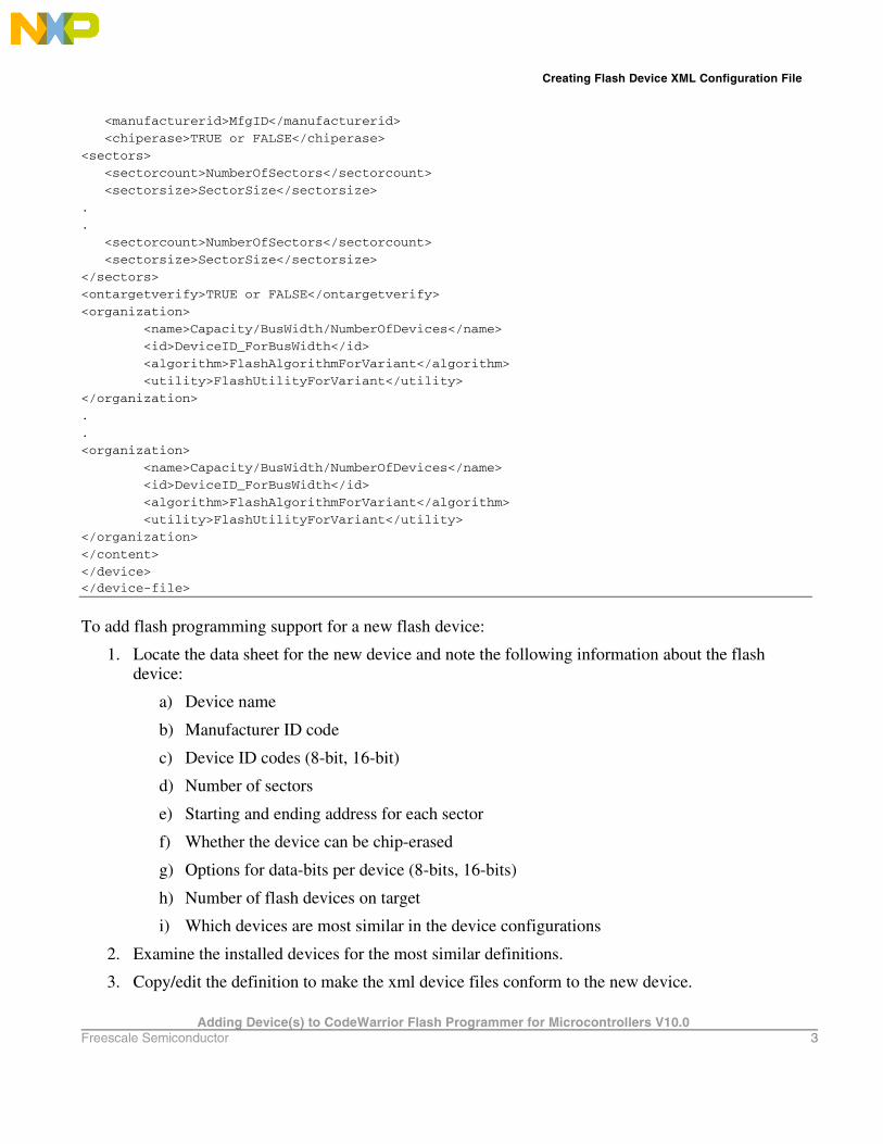
4. Creating Flash Device XML Configuration File In its default configuration, the CodeWarrior flash programmer supports many flash devices. The configuration files are located at: {CodeWarriorInstallDir}\MCU\bin\plugins\support\Products\ProductData\ColdFireFPDevices.mwpdb\FP, where CodeWarriorInstallDir is the location where CodeWarrior is installed. To add a new device to the CodeWarrior Flash Programmer, you must add a new file that describes the device. Listing 1 shows the file format.
Listing 1. Generic flash device file format
<device-file>
<device>
<content>
<name>NameOfFlashDevice</name>
Creating Flash Device XML Configuration File
Adding Device(s) to CodeWarrior Flash Programmer for Microcontrollers V10.0 Freescale Semiconductor 3
<manufacturerid>MfgID</manufacturerid>
<chiperase>TRUE or FALSE</chiperase>
<sectors>
<sectorcount>NumberOfSectors</sectorcount>
<sectorsize>SectorSize</sectorsize>
.
.
<sectorcount>NumberOfSectors</sectorcount>
<sectorsize>SectorSize</sectorsize>
</sectors>
<ontargetverify>TRUE or FALSE</ontargetverify>
<organization>
<name>Capacity/BusWidth/NumberOfDevices</name>
<id>DeviceID_ForBusWidth</id>
<algorithm>FlashAlgorithmForVariant</algorithm>
<utility>FlashUtilityForVariant</utility>
</organization>
.
.
<organization>
<name>Capacity/BusWidth/NumberOfDevices</name>
<id>DeviceID_ForBusWidth</id>
<algorithm>FlashAlgorithmForVariant</algorithm>
<utility>FlashUtilityForVariant</utility>
</organization>
</content>
</device> </device-file>
To add flash programming support for a new flash device:
1. Locate the data sheet for the new device and note the following information about the flash device:
a) Device name
b) Manufacturer ID code
c) Device ID codes (8-bit, 16-bit)
d) Number of sectors
e) Starting and ending address for each sector
f) Whether the device can be chip-erased
g) Options for data-bits per device (8-bits, 16-bits)
h) Number of flash devices on target
i) Which devices are most similar in the device configurations
2. Examine the installed devices for the most similar definitions.
3. Copy/edit the definition to make the xml device files conform to the new device.

Creating Flash Device XML Configuration File
Adding Device(s) to CodeWarrior Flash Programmer for Microcontrollers V10.0 4 Freescale Semiconductor
4.1. Device Name This is a free-form text field that describes the flash device, taken directly from the data sheet. Use only displayable ASCII characters with no spaces. Some examples, found in the configurations folder are: AM29BDD160GB, AM29LV640M, and IN28F128J3. The format is:
<name>NameOfFlashDevice</name>
4.2. Manufacturer ID Code and Device ID Codes These Manufacturer ID and Device ID are read from the flash device after a specific sequence of writes to the flash device. Although, the data sheet lists both of the IDs, only the Device ID varies among the flash devices from a given vendor, as the Manufacturer ID remains the same. If the flash device supports more than one bus width (8-bit, 16-bit), then it might have different Device ID for each mode. For example, AM29LV160BB. The formats are:
<manufacturerid>MfgID</manufacturerid> <id>DeviceID_ForBusWidth</id>
4.3. Chip Erasing Some devices can be completely erased with one chip erase command and this is much faster than erasing the device sector by sector. Set the chip erase value to TRUE if your flash device supports this feature. The format is:
<chiperase>TRUE or FALSE</chiperase>
4.4. Number of Sectors and Sector Size The data sheet lists the information on sector and sector size. If the data sheet lists sector maps and tables for both 8-bit and 16-bit data options, use the 8-bit data option. The CodeWarrior flash programming algorithms require byte-level addresses for each sector. This constraint simplifies the design of the CodeWarrior flash programming interface for several data bus configurations and sizes. When the data sheet does not provide a byte-level address, the algorithm creates an 8-bit sector map for 16-, 32-, or 64-bit devices. Table 1 shows an example of converting a 16-bit sector map to an 8-bit map. The formats are:
<sectorcount>NumberOfSectors</sectorcount>

Creating Flash Device XML Configuration File
Adding Device(s) to CodeWarrior Flash Programmer for Microcontrollers V10.0 Freescale Semiconductor 5
<sectorsize>SectorSize</sectorsize> The sectorcount value is decimal while the sectorsize is hexadecimal. For example, consider AM29BDD160GB. The device has eight (8) sectors of 0x2000 bytes each followed by 30 sectors of 0x10000 bytes and another eight (8) sectors of 0x2000. The configuration file will contain:
<sectors> <sectorcount>8</sectorcount> <sectorsize>2000</sectorsize> <sectorcount>30</sectorcount> <sectorsize>10000</sectorsize> <sectorcount>8</sectorcount> <sectorsize>2000</sectorsize> </sectors>
Table 1. Sector Map Conversion 16-b it Sec tor Map (64K word sec tors ) 8-b it Sec tor Map (128Kbyte s ec tors ) 000000..00FFFF 00000..01FFFF
010000..01FFFF 20000..03FFFF
020000..02FFFF 40000..05FFFF
030000..03FFFF 60000..07FFFF
Older flash devices can have sectors of different sizes. If you use such an older device, ensure that each sector in the configuration file is of the correct size.
4.5. Options for Organization Name The information that must be specified as an organization name includes: device size, bus width, and number of devices present on board. Device size is the size of the device. It can be expressed as KB or MB using K and M suffixes. Examples: 128K, 1M. Many flash devices can be set to use either 8-data bits or 16-data bits depending on the status of a configuration pin (typically named BYTE#) on each device. The <organization> field uses this part of the flash definition, as described in the next paragraph. Your target uses only one configuration so you need to support only that configuration. Expanding your new definition to include the other configurations for this device, however, is good design practice. Your target may use one, two, or four devices at the same base address to support an 8-bit, 16-bit, 32-bit, or 64-bit data bus.

Creating Flash Device XML Configuration File
Adding Device(s) to CodeWarrior Flash Programmer for Microcontrollers V10.0 6 Freescale Semiconductor
For example, two 8-bit flash devices side-by-side support a 16-bit data bus, and four 16-bit devices support a 64-bit data bus. The <organization> field summarizes each possible combination of device capacity, bus width, and number of devices used. For example, 4Mx16x1 means 4MegHalfwords by 16 data bits per device by 1 flash device, resulting in a total of 4M 16-bit half words. Similarly, 1Mx8x4 means 1MegaByte by 8 data bits per device by 4 flash devices, resulting in 1M 32-bit words and a 32-bit data bus presented to the processor. The format is:
<organization> <name>Capacity/BusWidth/NumberOfDevices</name> . . </organization>
4.6. Find Most Similar Device To find a device most similar to the one for which support is introduced, perform these steps:
1. From the data sheet for target flash devices, determine whether the bus width is 8- or 16- data bits.
2. Read through the files in the configuration folder of the CodeWarrior Development Studio for Microcontrollers V10.0 installation and scan for devices from the same manufacturer with similar part names. For example, AM29LV640D is similar to AM29LV641DU, and IN28F128J3 is similar to IN28F640J3.
3. Manufacturers often base new designs on the architecture of previous designs to ensure that new devices are virtually the same as the previous devices. However, the new devices may have greater capacity or improved programming features, such as timing and operation. This pattern simplifies flash programming because the flash programming algorithms remain unchanged. Yet only the device names, sectors, and Device IDs change.
4. Open the IN28F640J3.xml file in a text editor and compare the entries with the ones in IN28F128J3.xml. For example, see how the latter was built as an extension of the former. Note also how the part number of your device may be only a revision letter different from a defined part. For example, the flash programmer considers AM29DL640B to be the same as AM29DL640D and AM29DL640G. Thus, if you use a part number like this, program the flash programmer so you are using the defined part and do not need to create a new file.
The format is: <algorithm>FlashAlgorithmForVariant</algorithm>

Creating Flash Device XML Configuration File
Adding Device(s) to CodeWarrior Flash Programmer for Microcontrollers V10.0 Freescale Semiconductor 7
FlashAlgorithmForVariant is the algorithm name without full path (just the .elf file name).
4.7. Select Flash Programming Algorithm Flash programming algorithms differ depending on the flash manufacturer, bits per device organization, and the number of the flash devices used. The CodeWarrior flash programmer supports a number of algorithms that are already compiled *.elf executables. These files can be found at: {CodeWarrior}\MCU\bin\plugins\support\Flash_Programmer\ColdFire. Create an algorithm file name by combining the fields: manufacturer, data bits per device, and number of flash devices. For example, the flash algorithm for two AMD29LV320MB devices, used in their 16-bit mode (BYTE# = 1), is amd16x2.elf. The CodeWarrior Development Studio for Microcontrollers V10.0 has built-in flash programming algorithm support for AMD and Intel flash devices. If the device does not have built-in algorithm support, you can create your own algorithm and use it with the CodeWarrior flash programmer. For more information, refer to Creating External Flash Algorithm.
4.7.1. AMD or Spansion Based Flash Programming Algorithms
AMD or Spansion based devices use two types of flash programming algorithms: common and alternative. If the flash memory device supports two types of connections — 8-bits or byte connection and 16-bit or word connection — use an alternative algorithm. In all other cases or for the AMD flash devices that do not support two types of connections, use the common AMD algorithm (Table 2). Flash command register addresses are the main difference between common and alternative algorithms. For example, command addresses for the common flash algorithm are: 0x555, 0x2aa, 0x555, while for alternative connection these addresses are: 0xaaa, 0x555, 0xaaa. Table 2. AMD Algorithms Algorithm Device (s ) Addres s Us ed Algorithm File Name AMD One device that supports only 8-bits bus
connection 0x555, 0x2aa, 0x555 amd8x1.elf
AMD One device that supports both 8-bit and 16-bit bus connection in 8-bit mode
0x555, 0x2aa, 0x555 amd8x1alt.elf
AMD Two devices that support only 8-bits bus connection
0x555, 0x2aa, 0x555 amd8x2.elf
AMD Two devices that support both 8-bit and 16-bit bus connection in 8-bit mod
0xaaa, 0x555, 0xaaa amd8x2alt.elf
Creating Flash Device XML Configuration File
Adding Device(s) to CodeWarrior Flash Programmer for Microcontrollers V10.0 8 Freescale Semiconductor
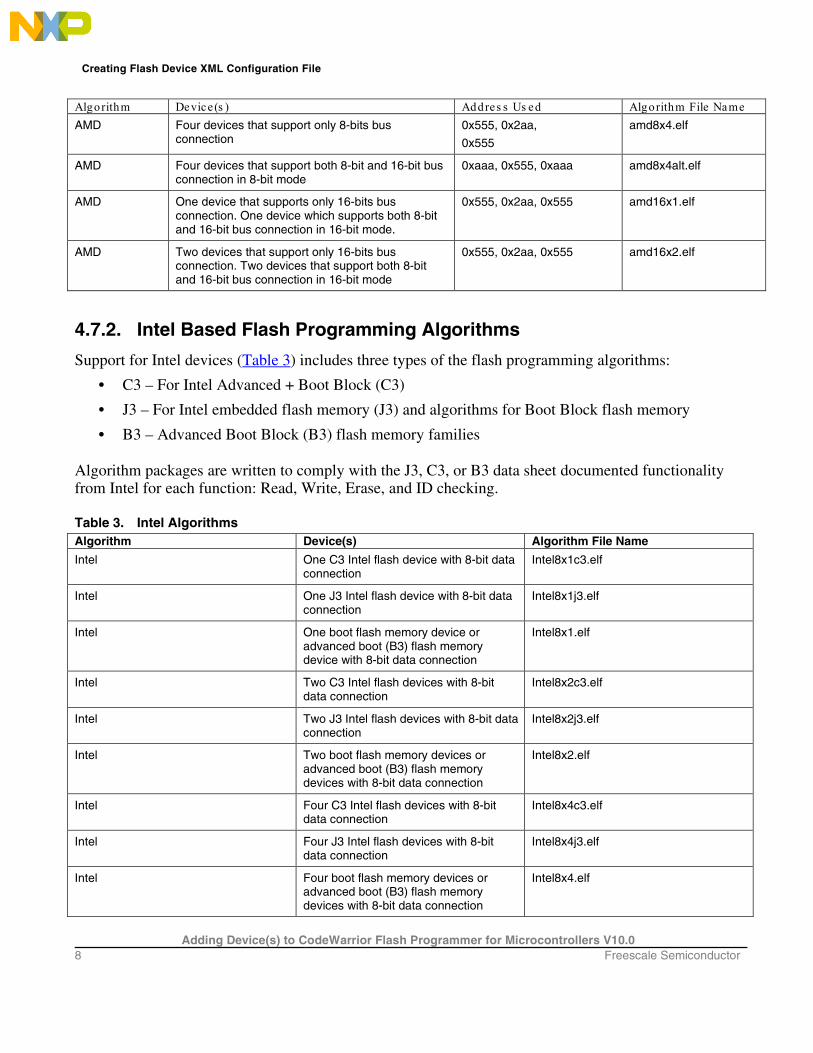
Algorithm Device (s ) Addres s Us ed Algorithm File Name AMD Four devices that support only 8-bits bus
connection 0x555, 0x2aa,
0x555
amd8x4.elf
AMD Four devices that support both 8-bit and 16-bit bus connection in 8-bit mode
0xaaa, 0x555, 0xaaa amd8x4alt.elf
AMD One device that supports only 16-bits bus connection. One device which supports both 8-bit and 16-bit bus connection in 16-bit mode.
0x555, 0x2aa, 0x555 amd16x1.elf
AMD Two devices that support only 16-bits bus connection. Two devices that support both 8-bit and 16-bit bus connection in 16-bit mode
0x555, 0x2aa, 0x555 amd16x2.elf
4.7.2. Intel Based Flash Programming Algorithms
Support for Intel devices (Table 3) includes three types of the flash programming algorithms:
• C3 – For Intel Advanced + Boot Block (C3)
• J3 – For Intel embedded flash memory (J3) and algorithms for Boot Block flash memory
• B3 – Advanced Boot Block (B3) flash memory families Algorithm packages are written to comply with the J3, C3, or B3 data sheet documented functionality from Intel for each function: Read, Write, Erase, and ID checking. Table 3. Intel Algorithms Algorithm Device(s) Algorithm File Name
Intel One C3 Intel flash device with 8-bit data connection
Intel8x1c3.elf
Intel One J3 Intel flash device with 8-bit data connection
Intel8x1j3.elf
Intel One boot flash memory device or advanced boot (B3) flash memory device with 8-bit data connection
Intel8x1.elf
Intel Two C3 Intel flash devices with 8-bit data connection
Intel8x2c3.elf
Intel Two J3 Intel flash devices with 8-bit data connection
Intel8x2j3.elf
Intel Two boot flash memory devices or advanced boot (B3) flash memory devices with 8-bit data connection
Intel8x2.elf
Intel Four C3 Intel flash devices with 8-bit data connection
Intel8x4c3.elf
Intel Four J3 Intel flash devices with 8-bit data connection
Intel8x4j3.elf
Intel Four boot flash memory devices or advanced boot (B3) flash memory devices with 8-bit data connection
Intel8x4.elf

Creating Flash Device XML Configuration File
Adding Device(s) to CodeWarrior Flash Programmer for Microcontrollers V10.0 Freescale Semiconductor 9
Algorithm Device(s) Algorithm File Name
Intel One C3 Intel flash device with 16-bit data connection
Intel16x1c3.elf
Intel One J3 Intel flash device with 16-bit data connection
Intel16x1j3.elf
Intel One boot flash memory device or advanced boot (B3) flash
memory device with 16-bit data connection
Intel16x1.elf
Intel Two C3 Intel flash devices with 16-bit data connection
Intel16x2c3.elf
Intel Two J3 Intel flash devices with 16-bit data connection
Intel16x2j3.elf
Intel Two boot flash memory devices or advanced boot (B3) flash
memory devices with 16-bit data connection
Intel16x2.elf
4.7.3. Flash Manufacturers Overview
Many manufacturers use flash device programming algorithms that are not bundled with their own devices. In many cases, these algorithms are same across multiple manufacturers. For example, AMIC 16x1 and AMD 16x1 flashes are programmed using the same algorithms. Table 4 lists algorithms, device compatibility, and other information for flash manufacturers. Table 4. Flash Manufacturers Manufacturer Algorithm Comments
Alliance Flash programming algorithms used for AMD (Spansion) should be usable (check flash device specification from manufacturer).
Manufacturer’s site: http://www.alsc.com/
AMD Algorithms are supported in the CodeWarrior flash programmer
AMD does not produce its own flash devices any more – founder of the Spansion Company. Manufacturer’s site:
http://www.spansion.com
AMIC Depending on the particular flash device for flash programming the same flash programming algorithms used for AMD (Spansion) or Atmel should be usable (check flash device specification from manufacturer).
Manufacturer’s site: http://www.amictechnology.com/
Atmel Flash programming algorithms are not supported in the CodeWarrior for ColdFire flash programmer.
Manufacturer’s site: http://www.atmel.com/
Catalyst Flash programming algorithms used for Intel should be usable (check flash device specification from manufacturer).
Manufacturer’s site: http://www.catsemi.com/index.html
Most of the flash devices from Catalyst are identical to the flash devices from Intel. For example: the CAT28F001 from Catalyst is the same as Intel E28F001.

Creating Flash Device XML Configuration File
Adding Device(s) to CodeWarrior Flash Programmer for Microcontrollers V10.0 10 Freescale Semiconductor
Manufacturer Algorithm Comments
EON Flash programming algorithms used for AMD (Spansion) should be usable (check flash device specification from manufacturer).
Manufacturer’s site: http://www.eonsdi.com/
Most of the flash devices from EON have direct references to the AMD flash devices.
Fujitsu Flash programming algorithms used for AMD (Spansion) should be usable (check flash device specification from manufacturer).
Fujitsu no longer produces its own flash devices– founder of the Spansion Company
Manufacturer’s site: http://www.spansion.com/
Hyundai Flash programming algorithms used for AMD (Spansion) should be usable (check flash device specification from manufacturer).
Hyundai founded new company for semiconductors, named Hynix.
Manufacturer’s site: http://www.hynix.com
Most of the flash devices from Hynix have direct references to the AMD flash devices.
Intel Algorithms are supported in the CodeWarrior flash programmer
Manufacturer’s site: http://www.intel.com/
Micron Flash programming algorithms used for Intel should be usable (check flash device specification from manufacturer).
Manufacturer’s site: http://www.micron.com/
Most of the flash devices from Micron have direct references to the Intel flashes
MXIC Flash programming algorithms used for AMD (Spansion) should be usable (check flash device specification from manufacturer).
Manufacturer’s site: http://www.mxic.com.tw
Most of the flash devices from MXIC have direct references to the AMD flash devices.
Samsung Flash programming algorithms are not supported in the CodeWarrior flash programmer.
Manufacturer’s site: www.samsung.com/products/semiconductor/OneNAND
Samsung uses its own algorithm for flash programming, not compatible with other vendors
Sharp Flash programming algorithms used for Intel should be usable (check flash device specification from manufacturer).
Manufacturer’s site: http://www.sharpsma.com
Spansion Algorithms are already supported in the CodeWarrior flash programmer
Manufacturer’s site: http://www.spansion.com/
SST Depending on the particular flash device, for flash programming the same flash programming algorithms used for AMD (Spansion), AMD or Intel should be usable (check flash device specification from manufacturer).
Produces flash devices compatible with Intel, AMD and Atmel
Manufacturer’s site: http://www.sst.com/about/
ST Flash programming algorithms used for AMD (Spansion) should be usable (check flash device specification from manufacturer).
Manufacturer’s site: http://www.st.com
Toshiba Flash programming algorithms used for Intel should be usable (check flash device specification from manufacturer).
Manufacturer’s site: http://www.semicon.toshiba.co.jp/eng
White Flash programming algorithms used for AMD (Spansion) should be usable (check flash device specification from manufacturer).
Manufacturer’s site: http://www.wedc.com/
Creating Flash Device XML Configuration File
Adding Device(s) to CodeWarrior Flash Programmer for Microcontrollers V10.0 Freescale Semiconductor 11
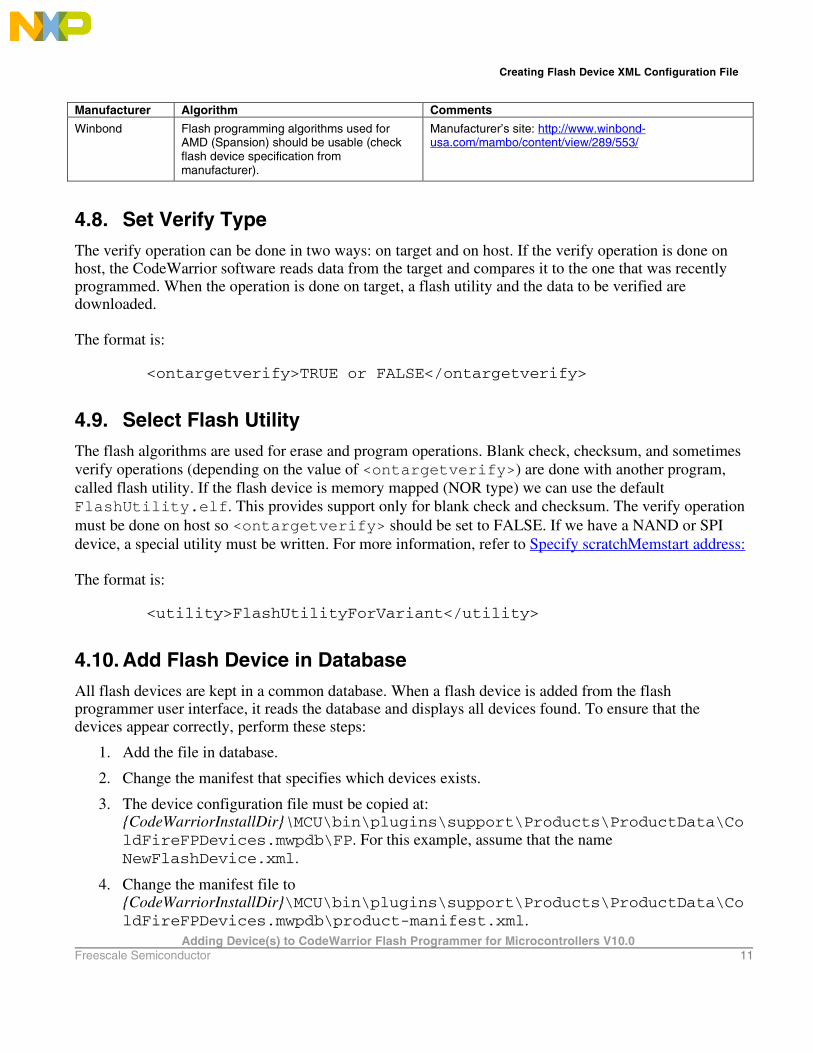
Manufacturer Algorithm Comments
Winbond Flash programming algorithms used for AMD (Spansion) should be usable (check flash device specification from manufacturer).
Manufacturer’s site: http://www.winbond-usa.com/mambo/content/view/289/553/
4.8. Set Verify Type The verify operation can be done in two ways: on target and on host. If the verify operation is done on host, the CodeWarrior software reads data from the target and compares it to the one that was recently programmed. When the operation is done on target, a flash utility and the data to be verified are downloaded. The format is:
<ontargetverify>TRUE or FALSE</ontargetverify>
4.9. Select Flash Utility The flash algorithms are used for erase and program operations. Blank check, checksum, and sometimes verify operations (depending on the value of <ontargetverify>) are done with another program, called flash utility. If the flash device is memory mapped (NOR type) we can use the default FlashUtility.elf. This provides support only for blank check and checksum. The verify operation must be done on host so <ontargetverify> should be set to FALSE. If we have a NAND or SPI device, a special utility must be written. For more information, refer to Specify scratchMemstart address: The format is:
<utility>FlashUtilityForVariant</utility>
4.10. Add Flash Device in Database All flash devices are kept in a common database. When a flash device is added from the flash programmer user interface, it reads the database and displays all devices found. To ensure that the devices appear correctly, perform these steps:
1. Add the file in database.
2. Change the manifest that specifies which devices exists.
3. The device configuration file must be copied at: {CodeWarriorInstallDir}\MCU\bin\plugins\support\Products\ProductData\ColdFireFPDevices.mwpdb\FP. For this example, assume that the name NewFlashDevice.xml.
4. Change the manifest file to {CodeWarriorInstallDir}\MCU\bin\plugins\support\Products\ProductData\ColdFireFPDevices.mwpdb\product-manifest.xml.
Creating Flash Device XML Configuration File
Adding Device(s) to CodeWarrior Flash Programmer for Microcontrollers V10.0 12 Freescale Semiconductor
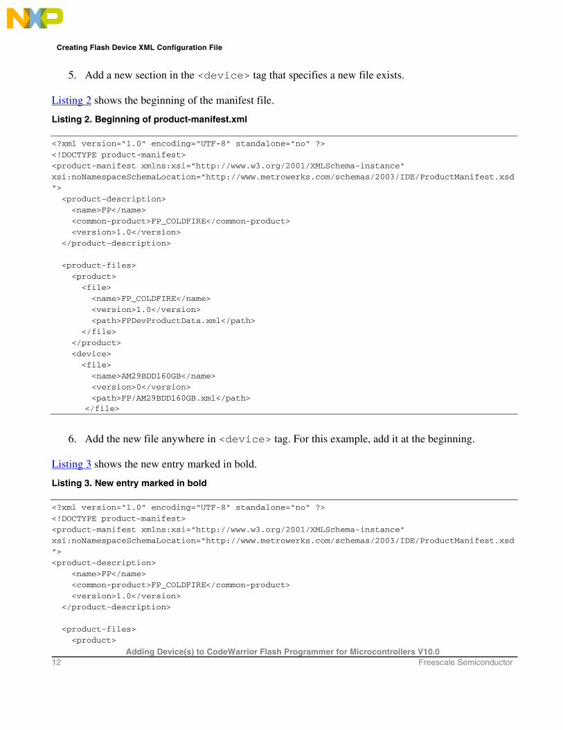
5. Add a new section in the <device> tag that specifies a new file exists. Listing 2 shows the beginning of the manifest file.
Listing 2. Beginning of product-manifest.xml
<?xml version="1.0" encoding="UTF-8" standalone="no" ?>
<!DOCTYPE product-manifest>
<product-manifest xmlns:xsi="http://www.w3.org/2001/XMLSchema-instance"
xsi:noNamespaceSchemaLocation="http://www.metrowerks.com/schemas/2003/IDE/ProductManifest.xsd
">
<product-description>
<name>FP</name>
<common-product>FP_COLDFIRE</common-product>
<version>1.0</version>
</product-description>
<product-files>
<product>
<file>
<name>FP_COLDFIRE</name>
<version>1.0</version>
<path>FPDevProductData.xml</path>
</file>
</product>
<device>
<file>
<name>AM29BDD160GB</name>
<version>0</version>
<path>FP/AM29BDD160GB.xml</path> </file>
6. Add the new file anywhere in <device> tag. For this example, add it at the beginning. Listing 3 shows the new entry marked in bold.
Listing 3. New entry marked in bold
<?xml version="1.0" encoding="UTF-8" standalone="no" ?>
<!DOCTYPE product-manifest>
<product-manifest xmlns:xsi="http://www.w3.org/2001/XMLSchema-instance"
xsi:noNamespaceSchemaLocation="http://www.metrowerks.com/schemas/2003/IDE/ProductManifest.xsd
">
<product-description>
<name>FP</name>
<common-product>FP_COLDFIRE</common-product>
<version>1.0</version>
</product-description>
<product-files>
<product>

Create New Target Task
Adding Device(s) to CodeWarrior Flash Programmer for Microcontrollers V10.0 Freescale Semiconductor 13
<file>
<name>FP_COLDFIRE</name>
<version>1.0</version>
<path>FPDevProductData.xml</path>
</file>
</product>
<device>
<file>
<name>NewFlashDevice</name>
<version>0</version>
<path>FP/NewFlashDevice.xml</path>
</file>
<file>
<name>AM29BDD160GB</name>
<version>0</version>
<path>FP/AM29BDD160GB.xml</path>
</file>
NOTE It is highly recommended to backup the manifest file before updating it. If an error
occurs, the CodeWarrior software may not be able to parse any of the devices.
5. Create New Target Task All Flash operations run through the Target Task Framework. To open the Target Tasks view:
1. Select Window > Show View > Other from the IDE menu bar. The Show View dialog box appears.
2. Select Debug > Target Tasks. The Target Tasks view appears. Next, create a flash programmer task representing the starting point for any flash operation. The task defines the flash device, the memory buffer, and the flash programmer actions .
5.1. Create New Task To create a new task, perform these steps:
1. Click the Create a new Target Task (“+”) icon on the Target Tasks view toolbar, as shown in Figure 1.

Create New Target Task
Adding Device(s) to CodeWarrior Flash Programmer for Microcontrollers V10.0 14 Freescale Semiconductor
Figure 1. Create a new Target Task Button
2. The Create New Target Task wizard appears (Figure 2). Specify information in the following fields:
• Task Name – Name of the target task.
• Task Group – Group where the task is to be created. If only Root exists, this option is disabled.
• Run Configuration – Each task must be associated with an existing Launch Configuration or Active Debug Context. This association is required to be able to make a connection to the target when doing operations over the flash. Active Debug Context means a connection is already established and only the task needs to be executed. Use Active Debug Context for generic tasks or when it is not known which Launch Configurations are available.
• Task Type – Type of task created. For ColdFire V234, select Flash Programmer for ColdFire V234.

Create New Target Task
Adding Device(s) to CodeWarrior Flash Programmer for Microcontrollers V10.0 Freescale Semiconductor 15
Figure 2. Create New Target Task Wizard
3. Click Finish. The editor for the new task appears.
5.2. Add Device to Target Task To add a flash device to the Flash Devices table in the Flash Programmer Task editor, perform these steps:
1. Select the flash programmer task to which you want to add a Flash device.
2. Click Add Device in the Flash Programmer Task editor. (Figure 3).

Create New Target Task
Adding Device(s) to CodeWarrior Flash Programmer for Microcontrollers V10.0 16 Freescale Semiconductor
Figure 3. Add Device in Flash Programmer Task Editor
The Add Device dialog box appears (Figure 4).
3. Select the required. You should select the devices that suit the board where the task will be executed. For example, select devices with organization AMD16x1 (Figure 4).
4. Click Add Device. A popup displays that the device has been added.

Create New Target Task
Adding Device(s) to CodeWarrior Flash Programmer for Microcontrollers V10.0 Freescale Semiconductor 17
Figure 4. Select Organization and Add Device Button
5. Click Done. The selected devices are added to the Flash Devices table.
5.3. Populate Default Values
• Base Address – Specifies base address for the devices in the Flash Devices table.
• Address in Target Ram panel – Specifies start address of the memory where an algorithm is downloaded on the target for performing operations on the flash devices
• Size – Specifies size of the memory buffer for algorithm. The size must be large enough to fit the algorithm and data that must be programmed. In case the buffer is not big enough, an error is displayed when executing the task. The smallest size needed is specified in the Size field.
• Verify Target Writes – Checks if the memory is correctly written. This is done by reading the memory written after each write command. This allows you to check if the RAM memory is correctly initialized. By default, it comes unchecked due to the loss of speed that comes with the overhead of reading memory each time.
All these values must be correct for the board where the flash device is located. Figure 5 shows the default values defined for board M5235EVB. All fields that must be filled are highlighted in red.

Create New Target Task
Adding Device(s) to CodeWarrior Flash Programmer for Microcontrollers V10.0 18 Freescale Semiconductor
Figure 5. Default Values for Board M5235EVB
5.4. Create Default Actions The various flash programmer actions that can be added to a target task are:
• Erasing the whole flash device using Chip Erase.
• Blank checking the whole device.
• Programming the file from Launch Configuration used to connect to the target.
• Verifying the file from Launch Configuration used to connect to the target. You can associate these actions with the target task using the buttons in the Flash Programmer Actions section in the Flash Programmer Task editor. You can arrange the order of the actions using the Move Up/Move Down buttons.
5.4.1. Erase / Blank Check Action
The erase action lets you to erase a selected sector from the flash device and the blank check action checks the erased sectors in the flash device. To add an erase / blank check action:

Create New Target Task
Adding Device(s) to CodeWarrior Flash Programmer for Microcontrollers V10.0 Freescale Semiconductor 19
1. Select the flash programmer task to which you want to add program or verify actions.
2. Click the Add Erase / Blank Check Action button in the Flash Programmer Task editor. The Add Erase / Blank Check Action dialog box appears.
3. Select the flash device to which you want to add the erase/blank check action.
4. Select a sector from the Sectors table and click Add Erase Action to add an erase operation on the selected sector. You can select multiple sectors by holding CTRL key while selecting the sectors.
5. Select a sector from the Sectors table and click Add Blank Check Action to add a blank check operation on the selected sector.
6. Check the Erase All Sectors Using Chip Erase Command checkbox to erase entire flash. You need to erase the entire flash if the size of file to be programmed is unknown. Also, to write something in flash, you need to erase it first or you will not be able to write the new information.
NOTE For more details regarding these operations, refer to Flash Programming Algorithm for
AMD 16x1 Flash Devices.
Figure 6. Add Erase / Blank Check Action Dialog Box

Create New Target Task
Adding Device(s) to CodeWarrior Flash Programmer for Microcontrollers V10.0 20 Freescale Semiconductor
7. Click Done to close the Add Erase / Blank Check Action dialog box. The added erase / blank check action appears in the Flash Programmer Actions table (Figure 7).
Figure 7. Erase and Blank Check Actions Added
5.4.2. Add Program / Verify Action
The Program action allows the user to specify the file that will be programmed, the location and various restrictions. The Verify action checks if a file has been programmed without errors. The parameters for verify and program in this case should be the same. To add a program or verify action:
1. Select the flash programmer task to which you want to add program or verify actions.
2. Click the Add Program / Verify Action button in the Flash Programmer Task editor. The Add Program / Verify Action dialog box appears.
3. Select the flash device to which you want to add a program or verify action.
4. Check the Use File from Launch Configuration checkbox if you want to program/verify the launch configuration file. Alternatively, specify the file name and file path in the File text box or click the Workspace, File System, or Variables buttons to select the desired file. • Click the Workspace button to select a file from the current Eclipse workspace. • Click the File System button to browse through the Windows file system and select the file.

Create New Target Task
Adding Device(s) to CodeWarrior Flash Programmer for Microcontrollers V10.0 Freescale Semiconductor 21
• Click the Variables button to insert variables in the path.
5. Define how the file should be read by selecting appropriate option from the File Type drop-down list. The following options are available: — Auto – the Flash Programmer automatically detects files of type Elf and Srec — Elf – elf executable file
— Srec – Motorola .s19 file format — Binary – the file is read in binary format, no content interpretation is done.
6. Check the Restrict to Addresses in this Range checkbox to define a range for flash accesses. Any program/verify action performed outside this range is ignored. You can specify the range in the Start and End text boxes, respectively.
7. Check the Apply Address Offset checkbox to apply an offset to the image to be written to the flash device. You can specify the offset in the Address text box. This value is added to the (computed) start address of the file. The start address is zero for binary files or read from the file header. In case you want to use a binary file and the flash is not mapped to zero, enable the offset and set the value to the base address of the flash. The settings are displayed in Figure 8.
8. Click the Add Program Action button to add a program action to the flash device.
9. Click the Add Verify Action button to verify an action for the flash device.
10. Click Done to close the Add Program / Verify Action dialog box.
Figure 8. Add Program / Verify Action Dialog Box
The added program / verify actions appear in the Flash Programmer Actions table as shown in Figure 9.

Create New Target Task
Adding Device(s) to CodeWarrior Flash Programmer for Microcontrollers V10.0 22 Freescale Semiconductor
Figure 9. Flash Programmer Actions Table
5.5. Storing Task After adding the required actions, you can save the task to an external file or framework..

Create New Target Task
Adding Device(s) to CodeWarrior Flash Programmer for Microcontrollers V10.0 Freescale Semiconductor 23
Figure 10. Store Task Dialog Box
To store the task:
1. Press Ctrl + S or click the Save button on the IDE toolbar. The Store Task dialog box appears.
2. Select one of the following options:
— Save to framework only: Saves the task in the task framework.
— Save to file: Saves the task to an external file. Specify the path where you want to store the task in the Task Path text box. You can use the Workspace, File System, or Variables buttons to navigate to the desired location. From the Project drop-down list, select the project where you want to store the target task.
NOTE Check the Do not ask me again for this task checkbox to save these settings for the current target task. If the Do not ask me again for this task checkbox is checked, the Store Task dialog box does not appear again on clicking the Save button.
3. Click OK. The dialog box closes.
NOTE If you do not want the Store Task dialog box to appear on clicking the Save button and
always save the target task in the task framework, select Window > Preferences > C/C++ > Debug > CodeWarrior Debugger and clear the Show "Save As" dialog when saving a new task checkbox.
5.6. Export Task The final step is exporting the task to an .xml file. To export a task:

Creating External Flash Algorithm
Adding Device(s) to CodeWarrior Flash Programmer for Microcontrollers V10.0 24 Freescale Semiconductor
1. In the Target Tasks view, select the task that you want to export. Click the icon on the Target Tasks view toolbar. Alternatively, right-click the task and select Export.
The Save As dialog box appears.
Figure 11. Export Target Task
2. Browse to the desired location, specify the filename, and click the Save button. The saved task can be imported later using the Import button on the Target Tasks view toolbar.
6. Creating External Flash Algorithm
6.1. Preliminary Background Before you program or erase any flash device, you must ensure that the CPU can access it. For example, you might need a different debug setup that requires modifications to the debugger configuration file. Consider the following before you begin:
• Read the flash device ID to verify correct connection and programmability. Refer to Troubleshooting Flash Programmer for instructions.
• Many manufacturers use the same flash-device algorithms, so it is likely that flashes can be programmed using algorithms included with CodeWarrior software. In addition, many manufacturers produce devices compatible with Intel or AMD.
• Check whether a new flash device can be programmed with an algorithm already included with the CodeWarrior software, as described in Select Flash Programming Algorithm.
• Follow the steps in Creating External Flash Algorithm if the flash device cannot be programmed with an existing algorithm.

Creating External Flash Algorithm
Adding Device(s) to CodeWarrior Flash Programmer for Microcontrollers V10.0 Freescale Semiconductor 25
6.2. Flash Tool Kit (FTK) Overview The Flash Took Kit (FTK) helps you develop flash programming algorithms for the CodeWarrior flash programmer (Figure 12).
Figure 12. Flash Tool Kit
6.3. Flash Tool Kit (FTK) General Structure The flash programmer FTK application is divided into three different sets of files:
• FTK Common Files (No Modification Needed): Includes initialization and other files. This component is common for all flash devices and you should not change it while developing the new flash programming algorithm. It consists of the following files:
— flash_algorithm.lcf file – linker command file. This linker command file is set up according to the rules for the flash programming applet allocation in physical memory.
— flash_commands.h – header file with API to CodeWarrior flash programmer commands definition.
— generic.h – header file with the generic data structures and definitions used by the flash programming algorithms.
— exit.c – exit point for the flash programming applet.
— _flash_start.c – flash programmer start-up initialization file.
— _flash_main.c – main function and API to the CodeWarrior flash programmer.
• User Files (Implement Algo): Includes flash device specific files. This component is modified for any flash devices depending on the flash programming algorithm to be used. It consists of the following files:
Common Part
User Part

Creating External Flash Algorithm
Adding Device(s) to CodeWarrior Flash Programmer for Microcontrollers V10.0 26 Freescale Semiconductor
— algo_impl.c – functions to implement for the flash device flash algorithm, such as ID, erase_sector, erase_chip, write.
• User Files (Implement Algo Tests): Includes flash device specific files. This component is considered to be modified for any flash devices depending on the flash programming algorithm to be used. It consists of the following files:
— flash_test.c – sample code with the flash unit test functionality implementation.
— flash_device.h – custom flash device definition file.
— flash_info.txt – contains CodeWarrior flash programmer commands. description. To create the new algorithm for flash programming, make all changes to the algo_impl.c (flash device algorithm implementation) and flash_device.h/flash_test.c files (flash device tests).
6.4. Flash Tool Kit (FTK) Build Targets Several build targets are predefined in FTK:
• Flash Algo Development – flash algorithm development and test application. The ELF executable file, created in Flash Algo Development, should be used to develop, debug, and test the new CodeWarrior flash programmer algorithm.
• Flash Algo Release – create flash algorithm applet. CodeWarrior flash programmer uses the ELF executable file, created in Flash Algo Release. This build target shares the flash device algorithm with the Flash Algo Development build target; it differs, however, because it cannot be debugged or tested (Figure 13.)
Figure 13. Flash Tool Kit Targets
6.5. Flash Programmer API The CodeWarrior flash programmer communicates with the flash programming algorithm applet through five different commands:

Creating External Flash Algorithm
Adding Device(s) to CodeWarrior Flash Programmer for Microcontrollers V10.0 Freescale Semiconductor 27
• get ID
• erase sector
• erase chip
• program
• verify The CodeWarrior flash programmer uses an exchange zone in target memory to communicate with the flash applet. The Flash Programmer target configuration specifies the target memory buffer; the exchange zone is at the start of this buffer, as shown in Figure 14.
Figure 14. Target Configuration Buffer Memory Area Start Address
In this sdk, scratchMemStart is the starting address of this zone. Depending on the actions the Flash Programmer requires of the applet, these exchange zone settings may differ.
Parameter_block_t Structure
On the flash applet side, the commands from the CodeWarrior flash programmer go through the Parameter_block_t structure, mapped in memory, starting from the scratchMemStart address.
All commands from CodeWarrior flash programmer are already encoded in the flash_main.c file. This file can be used for the new flash programming algorithm without changes. After loading the flash applet to the target board, the CodeWarrior flash programmer writes the startMemScratch address in the D7 register (Listing 4).

Creating External Flash Algorithm
Adding Device(s) to CodeWarrior Flash Programmer for Microcontrollers V10.0 28 Freescale Semiconductor
Listing 4. Parameter_block_t pointer initialization
void main(void)
{
unsigned long num_errors;
parameter_block_t *_params;
long res=0;
#ifdef FLASH_ALGO_TEST
int testnumber = 0;
_params = (parameter_block_t *)(unsigned int)&data_1;
#else
asm
{
move.l D7,res
}
_params = (parameter_block_t *)res;
For the detailed description of the Parameter_block_t structure, refer to Listing 5.
Listing 5. Parameter_block_t structure details
typedef struct pb {
unsigned long function; /* What function to perform ? */
pointer_t base_addr; /* where are we going to operate */
unsigned long num_items; /* number of items */
unsigned long result_status;
pointer_t items; } parameter_block_t;
Listing 5 definitions:
• function – command to be executed by the CodeWarrior flash programmer.
• base_addr – start address of the flash memory.
• num_items – number of items to be transferred from the CodeWarrior flash programmer to the flash programming applet.
• result_status – status of the command; through this field, the flash programming applet notifies the CodeWarrior flash programmer about the status of the command being executed.
• items – start address of the data to be transferred from the CodeWarrior flash programmer to the flash programming applet.
ID
The CodeWarrior flash programmer uses the getting chip ID command right after the flash algorithm is loaded to the memory buffer to check if the applet runs. For the ID command, the CodeWarrior flash programmer:
• loads the flash programming applet to the target board,
• sets the command ID, as shown in the function field of Listing 5,

Creating External Flash Algorithm
Adding Device(s) to CodeWarrior Flash Programmer for Microcontrollers V10.0 Freescale Semiconductor 29
• runs flash programming applet,
• waits while flash applet stops execution, and
• checks the status of the command being executed, as shown in the result_status field of Listing 5.
fEraseChip
The full chip erase command is called by CodeWarrior flash programmer when a full chip erase is performed. For the fEraseChip command, the CodeWarrior flash programmer:
• loads the flash programming applet to the target board,
• sets the command fEraseChip, as shown in the function field of Listing 5,
• runs the flash programming applet,
• waits while the flash applet stops execution, and
• checks the status of the command being executed, as shown in the result_status field of Listing 5.
NOTE Some flash devices do not support the full chip erase command. Check the flash device’s
specifications, available from the manufacturer.
fWrite
The fWrite program buffer command is called by the flash programmer to program a set of values at a specific address. For the fWrite command, the CodeWarrior flash programmer:
• loads the flash programming applet to the target board,
• sets the command fWrite, as shown in the function field of Listing 5,
• specifies number of bytes to be programmed, as shown in the num_items field of Listing 5,
• specifies start-up address of data to be programmed, as shown in the items field of Listing 5,
• runs flash programming applet,
• waits while flash applet stops execution, and
• checks the status of the command being executed, as shown in the result_status field of Listing 5.
fVerify
The fVerify function is identical to the fWrite function but instead of programming the device, the fVerify function checks if the file programmed actually exists on target. It returns success if information exists, failure otherwise.

Creating External Flash Algorithm
Adding Device(s) to CodeWarrior Flash Programmer for Microcontrollers V10.0 30 Freescale Semiconductor
6.6. Create New Flash Programming Algorithm To create a new flash programming algorithm for a flash device, which is not supported by the CodeWarrior software, using FTK:
1. Store the original version of the FTK files in the CodeWarrior software. Copy the FlashToolKitTemplate folder from{CodeWarriorInstallDir}\MCU\ColdFire_Tools\FlashToolKit to a different working directory, where CodeWarriorInstallDir specifies the location where the CodeWarrior software is installed.
2. Import the FTK Template project:
a) Select File > Import. The Import dialog box appears.
b) Select General > Existing Projects into Workspace and click Next. The Import Projects page appears.
c) Click Browse to select the folder where you have copied the FlashToolkitTemplate folder. The Projects list gets populated with all the projects in the FlashToolkitTemplate folder.
d) Clear the checkboxes next to the projects that you do not want to import and click Finish. The imported project is displayed in the CodeWarrior Projects view in the C/C++ perspective, as shown in Figure 12. Check that the project is using the Flash Algo Development build target.
3. Select Run > Debug Configuration. The Debug Configuration dialog box appears.
4. Expand the CodeWarrior Download tree node and select the desired launch configuration.
5. Click the Debugger tab in the right panel.
6. Select the required target processor from the Target Processor drop-down list, as shown in Figure 15.
7. Specify required target initialization and memory configuration files for the connected hardware in the Target initialization file and Memory Configuration File text boxes. For supported Freescale Evaluation Boards, you can use the debugger configuration files (*.cfg), and the debugger memory files (*.mem) available with the CodeWarrior Development Studio: {CodeWarriorInstallDir}\MCU\ColdFire_Support\Initialization_Files For example, the configuration settings for the M5235EVB board are shown in Figure 15.

Creating External Flash Algorithm
Adding Device(s) to CodeWarrior Flash Programmer for Microcontrollers V10.0 Freescale Semiconductor 31
Figure 15. Launch Configuration Settings for M5235EVB Board
NOTE In case of custom hardware design, the debugger configuration and memory mapping
files should be written. Also, the memory initialization file for the flash device should be checked before trying to create the new flash programming algorithm.
8. Specify an alternate loading address.
a) The flash algorithm, a PIC\PID application, can run from anywhere in memory. An alternate loading address is where the flash applet code is loaded and executed on the target board. This address can be either in internal or in external RAM memory, as shown in Figure 16.
b) The Alternate Load Address should match the address where the code is linked. By default, the flash programming algorithm is compiled to start at address 0x500; refer to the TEXT start address value in the flash_algorithm.lcf linker command file as shown in Listing 6.
c) If the custom board’s address space where you want to debug the applet is other than 0x0, the alternate address must be changed. For example: if RAM is allocated starting from address 0x2000000, the alternate loading address will be 0x20000000+0x500 = 0x20000500.

Creating External Flash Algorithm
Adding Device(s) to CodeWarrior Flash Programmer for Microcontrollers V10.0 32 Freescale Semiconductor
Figure 16. Alternate Load Address
Listing 6. Code start address definition in flash_algorithm.lcf file
# Sample Linker Command File for CodeWarrior for ColdFire
# NOTE: The debugger uses the Illegal Instruction Vector to stop.
# A small subroutine is written at the location VBR+0x408-VBR+0x40B
# to handle the exception. The Illegal Instruction Vector in
# the vector table at VBR+0x10 is then pointed to it. When the
# debugger encounters an illegal instruction, it jumps to this
# subroutine, which ends with an RTE, then exits.
# Do not overwrite this area of memory otherwise the debugger may not
# exit properly.
MEMORY {
TEXT (RX) : ORIGIN = 0x00000500, LENGTH = 0 # using External DRAM
DATA (RW) : ORIGIN = AFTER(TEXT), LENGTH = 0 }
9. Specify scratchMemstart address:
a) In order to debug the flash algorithm correctly, set the scratchMemStart Start address in the flash_device.h file. An example of the scratchMemStart setting is shown in Listing 7.
b) The SCRATCH_MEM_ADDRESS value should be equal to: alternate loading address minus the compiled start address from the flash_algorithm.lcf file (0x500 default value). For example, if the alternate loading address is 0x20000500, then SCRATCH_MEM_ADDRESS = 0x20000500 – 0x500 = 0x20000000.
Listing 7. Setting the address of scratchMemStart in __flash_start.c
/* Flash Programmer SDK
* Copyright © 2007 Freescale Semiconductor. All rights reserved.
*/
/*************************************************************/
/* */
/* __flash_start.c */
/* */

Creating External Flash Algorithm
Adding Device(s) to CodeWarrior Flash Programmer for Microcontrollers V10.0 Freescale Semiconductor 33
/* This file provides support to the position independent */
/* code in TRD */
/* */
/*************************************************************/
asm void _flash_start(void);
extern void main( void );
extern unsigned long _SDA_BASE;
extern unsigned long stack_addr;
#ifdef FLASH_ALGO_TEST
#define SCRATCH_MEM_ADDRESS 0x0 #endif
10. Modify the algo_impl.c file:
a) The flash algorithm functionality file algo_impl.c should be modified and should include the correct programming commands, as recommended by the flash device manufacturer.
11. Modify ID function in the algo_impl.c file:
a) By default, the ID function in the algo_impl.c file looks as shown in Listing 8.
b) The following definitions pertain to Listing 8:
- parameter_block_t *p_pb – Pointer to the parameter_block_t structure to be passed to the ID function.
- retval_t – Result of the function execution.
c) The correct command sequence should be created for the ID function based on the recommendations of the flash device manufacturer, as described in Implementation of ID Function for AMD 16x1 Flash Devices.
Listing 8. ID function template in algo_impl.c file
retval_t ID(parameter_block_t *p_pb) { retval_t result = 0;
volatile unsigned long* item_addr = (p_pb->items).l;
/* Add code: the correct access size depending on the bus must be used for the base_addr
*/
volatile unsigned short *base_addr = (p_pb->base_addr).w;
/* Add code: first of all reset the device.
The fID is not called in the new flash programmer plugin therefore
the flash chip must always be brought into the read state.
*/
/* Add code: read the device ID */
/* we currently assume that we have the right value */
Creating External Flash Algorithm
Adding Device(s) to CodeWarrior Flash Programmer for Microcontrollers V10.0 34 Freescale Semiconductor
/* anyway, the IDE have to care about the flash ID and compare with the xml file */
return result; }
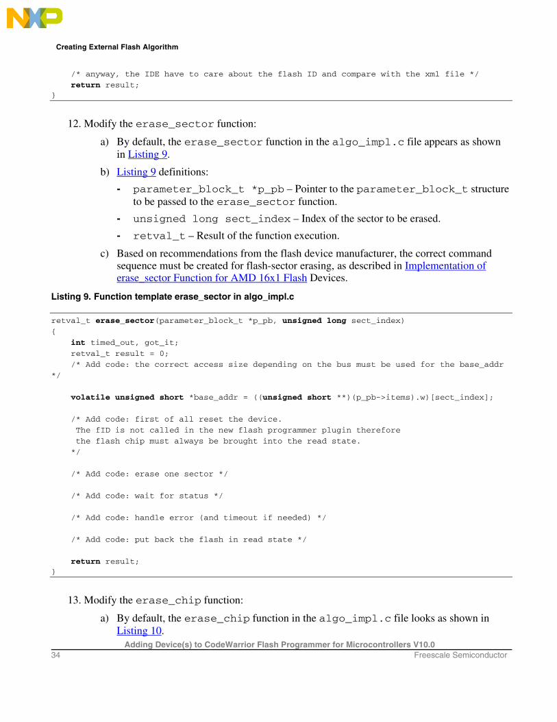
12. Modify the erase_sector function:
a) By default, the erase_sector function in the algo_impl.c file appears as shown in Listing 9.
b) Listing 9 definitions:
- parameter_block_t *p_pb – Pointer to the parameter_block_t structure to be passed to the erase_sector function.
- unsigned long sect_index – Index of the sector to be erased.
- retval_t – Result of the function execution.
c) Based on recommendations from the flash device manufacturer, the correct command sequence must be created for flash-sector erasing, as described in Implementation of erase_sector Function for AMD 16x1 Flash Devices.
Listing 9. Function template erase_sector in algo_impl.c
retval_t erase_sector(parameter_block_t *p_pb, unsigned long sect_index)
{
int timed_out, got_it;
retval_t result = 0;
/* Add code: the correct access size depending on the bus must be used for the base_addr
*/
volatile unsigned short *base_addr = ((unsigned short **)(p_pb->items).w)[sect_index];
/* Add code: first of all reset the device.
The fID is not called in the new flash programmer plugin therefore
the flash chip must always be brought into the read state.
*/
/* Add code: erase one sector */
/* Add code: wait for status */
/* Add code: handle error (and timeout if needed) */
/* Add code: put back the flash in read state */
return result; }
13. Modify the erase_chip function:
a) By default, the erase_chip function in the algo_impl.c file looks as shown in Listing 10.

Creating External Flash Algorithm
Adding Device(s) to CodeWarrior Flash Programmer for Microcontrollers V10.0 Freescale Semiconductor 35
b) Listing 10 definitions:
- parameter_block_t *p_pb – Pointer to the parameter_block_t structure to be passed to the erase_chip function.
- retval_t – Result of the function execution.
- Create the correct command sequence for full flash chip erasing based upon recommendations from the flash device manufacturer, as shown in Implementation of erase_chip Function for AMD 16x1 Flash Devices.
Listing 10. Function template erase_chip in algo_impl.c
retval_t erase_chip(parameter_block_t *p_pb)
{
int errors = 0;
retval_t result = 0;
unsigned short stat;
int got_it;
/* Add code: the correct access size depending on the bus must be used for the base_addr
*/
volatile unsigned short *base_addr = (p_pb->base_addr).w;
/* Add code: first of all reset the device.
The fID is not called in the new flash programmer plugin therefore
the flash chip must always be brought into the read state.
*/
/* Add code: erase one sector */
/* Add code: wait for status */
/* Add code: handle error (and timeout if needed) */
/* Add code: put back the flash in read state */
return result; }
14. Modify the write function:
a) By default, the write function in the algo_impl.c file looks as it appears in Listing 11.
b) Listing 11 definitions:
- parameter_block_t *p_pb – Pointer to the parameter_block_t structure to be passed to the write function.
- retval_t – Result of the function execution.
c) Create the correct command sequence for flash device programming according to the recommendations of the flash device manufacturer, as described in Implementation of Write Function for AMD 16x1 Flash Devices.

Creating External Flash Algorithm
Adding Device(s) to CodeWarrior Flash Programmer for Microcontrollers V10.0 36 Freescale Semiconductor
Listing 11. Function template write in algo_impl.c
retval_t write(parameter_block *p_pb)
{
int timed_out, got_it;
unsigned long i;
unsigned short stat;
retval_t errors = 0;
/* Add code: the correct access size depending on the bus must be used for the base_addr
*/
volatile unsigned short *base_addr = (p_pb->base_addr).w;
/* Add code: first of all reset the device.
The fID is not called in the new flash programmer plugin therefore
the flash chip must always be brought into the read state.
*/
/* Add code: program the bytes pointed in the buffer : p_pb->items,
they are p_pb->num_items bytes
handle error (and timeout if needed) for each of the program sequence
*/
/* Add code: put back the flash in read state */
return errors; }
15. Flash programming applet unit testing:
a) For flash programming algorithm testing, define custom flash device parameters in the flash_device.h file. The following parameters should have correct definitions:
- BASE_FLASH_ADDRESS – ColdFire CPU view of the flash device’s address.
- SCRATCH_MEM_ADDRESS – scratchMemStart address; refer to step 9.
- SECTOR_ADDRESS_OFFSET – Memory sector size.
- NUMBER_ITEMS – Test parameter, which defines how much data is programmed during the flash program testing.
b) Refer to Listing 12.
Listing 12. Flash programming applet parameters in flash_device.h
/* Flash Programming SDK
* Copyright © 2007 Freescale Semiconductor. All rights reserved.
*/
#include "generic.h"

Creating External Flash Algorithm
Adding Device(s) to CodeWarrior Flash Programmer for Microcontrollers V10.0 Freescale Semiconductor 37
/* Base Address of the flash */
#define BASE_FLASH_ADDRESS 0xFFE00000UL /* For AMD */
/* Offset of the sector to erase for the test */
#define SECTOR_ADDRESS_OFFSET 0x4000UL /* For AMD */
/* Number of bytes to program for the test
This parameter could not be more then Flash size
*/
#define NUMBER_ITEMS 1024
/* Set this to one if chip erase is supported */
#define HAS_CHIP_ERASE 0
NOTE Refer to the flash device manufacturer for the flash device memory organization. Refer
to hardware description for the flash device addressing.
16. Compile flash algo development target:
a) During new algorithm creation and testing, use the Flash Algo Development build target of the Flash Development Kit. Compile the Flash Algo Development target with the flash_algo.c file, which is modified for the flash programming procedures. Compilation will result in creation of a new FlashAlgDevelopment.elf file.
17. Flash algorithm unit test:
a) To simplify flash programming algorithm creation and testing, flash test functionality is included with FTK in the Flash Algo Development build target. Check the file flash_test.c for it. Unit test functions contain basic functionality required for the flash programming; the following tests are performed:
- checking flash device’s ID,
- erasing flash memory sector, and
- programming flash memory sector with the predefined data (in sample code the incrementing counter is used).
b) Load the file FlashAlgDevelopment.elf and run it on the target board. Check the tests results. As an example of the test working, refer to AMD 16x1 Flash Programming Algorithm Unit Testing.
18. Compile flash algo release target:
a) When the flash programming algorithm for the new flash device works correctly (as confirmed in unit testing), compile the Flash Algo Release target. The output of the Flash Algo Release target — FlashAlgRelease.elf— must be copied to the following folder: {CodeWariorInstallDir}\MCU\bin\plugins\support\Flash_Programmer\ColdFire

Creating External Flash Algorithm
Adding Device(s) to CodeWarrior Flash Programmer for Microcontrollers V10.0 38 Freescale Semiconductor
19. Add a new flash device to the flash programmer:
a) Refer section Creating Flash Device XML Configuration File for information about how to add a new flash device.
20. Create a new target task:
a) Refer section Create New Target Task for information about how to create a new target task.
21. Set flash device configuration in flash programmer:
a) Restart the Eclipse IDE so that the Eclipse IDE can use the updated manifest file.
b) Select Window > Show View > Other from the IDE menu bar.
c) Select Debug > Target Tasks from the Show View dialog box to open the Target Tasks view.
d) Right-click on the Tasks table and select Import from the context menu (Figure 17).
Alternatively, click the icon on the Target Tasks view toolbar to import a task. The Open dialog box appears.
Figure 17. Import Task
e) Browse to the location of the task that you want to import, select the required task, and click Open. The imported task gets added to the Tasks table.
f) Right-click the imported task and select Change Run Configuration.
g) Select FlashToolKit Development – PnE USB BDM from the Run Configuration drop-down list and click OK (Figure 18).

Creating External Flash Algorithm
Adding Device(s) to CodeWarrior Flash Programmer for Microcontrollers V10.0 Freescale Semiconductor 39
Figure 18. Change Run Configuration
h) Double click the task to open the task in the editor area.
i) Check if the flash device used is the newly introduced. As an example the device has been named AM29BDD160GB. See Figure 19.
Figure 19. Flash Task Editor
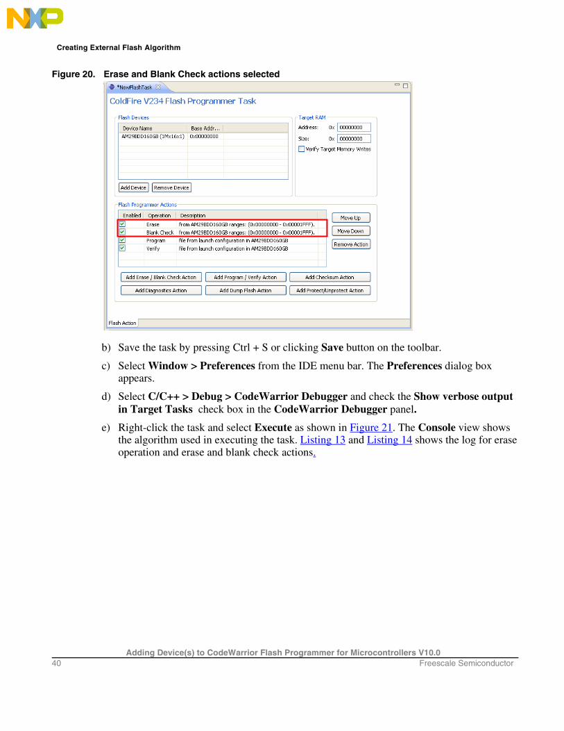
22. Erase and blank check the device:
a) Select only Erase and Blank Check actions as shown in Figure 20.
Creating External Flash Algorithm
Adding Device(s) to CodeWarrior Flash Programmer for Microcontrollers V10.0 40 Freescale Semiconductor
Figure 20. Erase and Blank Check actions selected
b) Save the task by pressing Ctrl + S or clicking Save button on the toolbar.
c) Select Window > Preferences from the IDE menu bar. The Preferences dialog box appears.
d) Select C/C++ > Debug > CodeWarrior Debugger and check the Show verbose output in Target Tasks check box in the CodeWarrior Debugger panel.
e) Right-click the task and select Execute as shown in Figure 21. The Console view shows the algorithm used in executing the task. Listing 13 and Listing 14 shows the log for erase operation and erase and blank check actions.

Creating External Flash Algorithm
Adding Device(s) to CodeWarrior Flash Programmer for Microcontrollers V10.0 Freescale Semiconductor 41
Figure 21. Execute Task
Listing 13. Algorithm used for Erase operation
.
cmdwin::fl::erase all
Beginning Operation ...
-------------------------
log: Using Algorithm: FlashAlgDevelopment.elf . .
Listing 14. Erase and Blank Check actions log
.
.
Erasing ............................
Reading erase return status
Erase Command Succeeded
.
.
Blank Checking ............
Reading blank check return status Blank Check Succeeded
NOTE In case the flash device cannot be erased, check successful erasure of flash device and hardware connection correctly setup.
23. Perform programming test: The binary S-record files of different sizes are available in the FTK delivery to check whether the flash device can be programmed. The path to the S-record files is: {CodeWarriorInstallDir}\MCU\ColdFire_Tools\FlashToolKit\TestSrecFiles Some of the S-record files at this location are: 64k_at_0.S, 128k_at_0.S, 256k_at_0.S, 1M_at_0.S, 2M_at_0.S, and 4M_at_0.S. The filename specify the size of the file. For example, file 256k_at_0.S is 256 Kilobyte in size and is linked to the 0 startup address.

Creating External Flash Algorithm
Adding Device(s) to CodeWarrior Flash Programmer for Microcontrollers V10.0 42 Freescale Semiconductor
a) Enable Program and Verify actions as shown in Figure 22. Save the task (Ctrl + S).
Figure 22. Program and Verify Actions
b) Double-click Program in the Operation column. The Add Program / Verify Action dialog box appears.
c) Clear the Use File from Launch Configuration checkbox and click the File System button to select a .S file to be programmed.
d) Check the Restrict to Addresses in this Range and Apply Address Offset checkboxes. Figure 23 shows the settings.
Figure 23. Edit Program / Verify Action

Creating External Flash Algorithm
Adding Device(s) to CodeWarrior Flash Programmer for Microcontrollers V10.0 Freescale Semiconductor 43
e) Figure 22 definitions:
- Restrict to Addresses in this Range - address range of the flash device
- Apply Address Offset - start address, where the test data is programmed in the flash; it should be the flash device start address.
f) Click the Update Program Action button.
g) Similarly update the Verify action.
h) Execute the task.
i) Check the Console view for the algorithms used in execution of the task, as shown in Listing 15
Listing 15. Programming test log
Downloading 0x00002800 bytes to be programmed at 0xFFEFD800
Writing Program Function Code
Writing the Address
Writing the Size
Writing the address of the buffer
Clearing the status
Setting up Registers
Commanding target to run
Programming ...
Reading program return status
Program Command Succeeded
log: Programmed total of 0x00100000 bytes
log:
log: Program Command Succeeded . . Uploading 0x00010000 bytes starting from address 0xFFEF0000
log: Uploading 0x00010000 bytes starting from address 0xFFEF0000
log: Verified total of 0x00100000 bytes

Flash Programming Examples
Adding Device(s) to CodeWarrior Flash Programmer for Microcontrollers V10.0 44 Freescale Semiconductor
log: Verify Command Succeeded
If all the program/verify actions pass correctly, you have completed creation of a new flash programming algorithm. The new flash device can be programmed with CodeWarrior flash programmer without limitation.
7. Flash Programming Examples
7.1. Flash Programming Algorithm for AMD 16x1 Flash Devices The AMD16x1Example project (Figure 24) illustrates how the Flash Development Kit is used with the AMD 16x1 flash algorithm.
Figure 24. CodeWarrior Projects View Displaying AMD16x1Example Project
7.1.1. Implementation of ID Function for AMD 16x1 Flash Devices
The sequence for getting the Manufacturer ID and Device ID, based on the AMD flash specification, is shown in Table 5. Table 5. ID Command Sequence for the AMD Flash
Command Sequence
Cyc
les Bus Cycles
First Second Third Addr Data Addr Data Addr Data

Flash Programming Examples
Adding Device(s) to CodeWarrior Flash Programmer for Microcontrollers V10.0 Freescale Semiconductor 45
Manufacturer ID 4 555 AA 2AA 55 (BA)555 90
Device ID 6 555 AA 2AA 55 (BA)555 90
Listing 16. ID function sample code for AMD flashes
retval_t ID(parameter_block_t *p_pb)
{
volatile unsigned short *baseaddress = (p_pb->base_addr).w;
retval_t result = 0;
/* reset */
*(baseaddress) = (unsigned short)0xF0F0;
/* setup for get id */
*(baseaddress + 0x555) = (unsigned short)0xAA;
*(baseaddress + 0x2AA) = (unsigned short)0x55;
*(baseaddress + 0x555) = (unsigned short)0x90;
#ifdef FLASH_ALGO_TEST
/* get id */
mf_id = *(baseaddress);
part_id = *(baseaddress + 1);
#endif
/* read mode again */
*(baseaddress) = (unsigned char)0xF0;
return result; }
When using the Algo Development build target, the device ID and manufacturer’s ID are read from the flash device and stored in the part_id and mf_id variables (Listing 16). Check these during the flash algorithm testing.
7.1.2. Implementation of erase_sector Function for AMD 16x1 Flash Devices
The sequence for the Sector Erase command implementation, based on the AMD flash specification, is shown in Table 6. Table 6. Sector Erase Command Sequence for AMD Flash
Command Sequence
Cyc
les Bus Cycles
First Second Third Fourth Fifth Sixth Addr Data Addr Data Addr Data Addr Data Addr Data Addr Data
Sector Erase
6 555 AA 2AA 55 555 80 555 AA 2AA 55 SA 30
Refer to the actual encoding of the erase_sector function for AMD flashes in Listing 17.

Flash Programming Examples
Adding Device(s) to CodeWarrior Flash Programmer for Microcontrollers V10.0 46 Freescale Semiconductor
Listing 17. Function erase_sector sample code for AMD flashes
retval_t erase_sector(parameter_block_t *p_pb, unsigned long sect_index)
{
volatile unsigned short *sectoraddress = ((unsigned short **)(p_pb-
>items).w)[sect_index];
volatile unsigned short read;
retval_t result = 0;
/* first of all reset the device. The fID is no longer called in the new
flash programmer plugin (it was used in the old AMC MWX-ICE) therefore
the flash chip must always be brought into the read state.
*/
/* reset sector */
*(sectoraddress) = (unsigned short)0xF0F0;
/* erase sector */
*(sectoraddress + 0x555) = (unsigned short)0xAA;
*(sectoraddress + 0x2AA) = (unsigned short)0x55;
*(sectoraddress + 0x555) = (unsigned short)0x80;
*(sectoraddress + 0x555) = (unsigned short)0xAA;
*(sectoraddress + 0x2AA) = (unsigned short)0x55;
*(sectoraddress) = (unsigned short)0x30;
read = *(sectoraddress);
/*
Wait for the status value to be read from *addr or
how_long ticks to pass. If how_long ticks pass,
a non-0 value will be returned.
On the AMD chips, DQ7 is inverted until the embedded
algorithm is completed when it flips to the correct
value. The parameter 'hi' will indicate whether that
value is set or cleared.
*/
while ((read & 0x0080) != 0x0080)
{
read = *(sectoraddress);
}
/* read mode again */
*(sectoraddress) = (unsigned char)0xF0;
return result; }

Flash Programming Examples
Adding Device(s) to CodeWarrior Flash Programmer for Microcontrollers V10.0 Freescale Semiconductor 47
7.1.3. Implementation of erase_chip Function for AMD 16x1 Flash Devices
The sequence for the Chip Erase command, based on the AMD flash specification, is shown in Table 7 and Listing 18. Table 7. Chip Erase Command Sequence for AMD Flash
Command Sequence
Cyc
les Bus Cycles
First Second Third Fourth Fifth Sixth Addr Data Addr Data Addr Data Addr Data Addr Data Addr Data
Chip Erase 6 555 AA 2AA 55 555 80 555 AA 2AA 55 555 10
Listing 18. Function erase_chip encoding for AMD flashes
retval_t erase_chip(parameter_block_t *p_pb)
{
int errors = 0;
retval_t result = 0;
unsigned short stat;
unsigned short mask = (unsigned short)DQ7;
unsigned short masked_src = (unsigned short)DQ7;
int got_it;
volatile unsigned short *base_addr = (p_pb->base_addr).w;
/* first of all reset the device. The fID is no longer called in the new
flash programmer plugin (it was used in the old AMC MWX-ICE) therefore
the flash chip must always be brought into the read state.
*/
*base_addr = 0xF0F0;
/* erase sector */
*(base_addr + 0x555) = (unsigned short)0xAA;
*(base_addr + 0x2AA) = (unsigned short)0x55;
*(base_addr + 0x555) = (unsigned short)0x80;
/* erase chip */
*(base_addr + 0x555) = (unsigned short)0xAA;
*(base_addr + 0x2AA) = (unsigned short)0x55;
*(base_addr + 0x555) = (unsigned short)0x10;
/* Wait for status operation */
mask &= 0x0080; /* Only dq7 flips */
masked_src &= 0x0080;
while ( 1 )
{
if ( (*base_addr & mask) == masked_src )
{
break;
}
}

Flash Programming Examples
Adding Device(s) to CodeWarrior Flash Programmer for Microcontrollers V10.0 48 Freescale Semiconductor
/* return to read mode */
*base_addr = 0xf0;
return result; }
7.1.4. Implementation of Write Function for AMD 16x1 Flash Devices
In terms of AMD flash devices specification, the write function realizes the Program command. The sequence for the Program command, according to the AMD specification, is shown in Table 8. Table 8. Program command sequence for AMD flash
Command Sequence
Cyc
les Bus Cycles
First Second Third Addr Data Addr Data Addr Data
Program 4 555 AA 2AA 55 555 A0
Refer to the actual encoding of the write function for AMD flashes in the algo_impl.c file as shown in Listing 19.
Listing 19. Sample write function code for AMD flashes
retval_t write(parameter_block_t *p_pb)
{
int timed_out, got_it;
unsigned long i;
unsigned short stat;
retval_t errors = 0;
unsigned short mask = (unsigned short)DQ7;
unsigned short masked_src = (unsigned short)DQ7;
volatile unsigned short *base_addr = (p_pb->base_addr).w;
unsigned short *buffer = (p_pb->items).w;
unsigned long buffer_len = p_pb->num_items;
unsigned long how_many = buffer_len / sizeof(unsigned short);
if ( buffer_len % sizeof(unsigned short) ) {
/* we need to fill the remaining bytes with 'ff' -- this assumes
byte accesses to DRAM will work */
char *p = (char *)((unsigned long)buffer + buffer_len);
*p++ = '\xff';
how_many++ ;
}
/* first of all reset the device. The fID is no longer called in the new
flash programmer plugin (it was used in the old AMC MWX-ICE) therefore
the flash chip must always be brought into the read state.
*/
*base_addr = (unsigned short)0xf0f0;
for (i = 0; (i < how_many) && !errors; i++){

Flash Programming Examples
Adding Device(s) to CodeWarrior Flash Programmer for Microcontrollers V10.0 Freescale Semiconductor 49
unsigned short *c = (unsigned short*)((unsigned long)base_addr & ~0x1fff);
*((c) + 0x555) = 0xaa;
*((c) + 0x2aa) = 0x55;
*((c) + 0x555) = 0xa0;
*base_addr = *buffer;
/* Wait for status operation */
mask &= 0x0080; /* Only dq7 flips */
masked_src = (unsigned short)((unsigned char)DQ7 & *buffer);
masked_src &= 0x0080;
while ( 1 )
{
if ( (*base_addr & mask) == masked_src )
{
break;
}
}
base_addr++;
buffer++;
}
/* go back to the last access */
--base_addr;
/* read mode again */
*base_addr = (unsigned char)0xf0;
return errors; }
7.2. AMD 16x1 Flash Programming Algorithm Unit Testing This section illustrates an example flash test application working with AMD 16x1. The flash programming applet is tested on a Freescale M5235EVB with an AM29PL160CB flash device.
7.2.1. Flash Testing Setup
Use the Algo Development target — shown in Figure 25— to run the flash programming test application. Upon loading, the application stops at the _flash_start() function as shown in Figure 25.

Flash Programming Examples
Adding Device(s) to CodeWarrior Flash Programmer for Microcontrollers V10.0 50 Freescale Semiconductor
Figure 25. Unit Test Application Start-up Point
7.2.2. Test I: Read Manufacturer and Device ID
After the execution of the Run command, the application stops at the first test check point, as shown in Figure 26.
Figure 26. Read Manufacturer and Device ID
The results of Test I display the manufacturer ID code 0x01 (for AMD) and the device ID code 0x2245 (for the Am29PL160CB flash device). This confirms basic read/write functionality of the flash devices.

Flash Programming Examples
Adding Device(s) to CodeWarrior Flash Programmer for Microcontrollers V10.0 Freescale Semiconductor 51
7.2.3. Test II: Erase a Sector
With another Run command execution the application stops at the Test II check point, as shown in Figure 29. In Test II, the sector number one of the flash memory is erased. From the sample flash device definition for AMD 16x1, we have: BASE_FLASH_ADDRESS equal to 0xFFE00000 and the SECTOR_ADDRESS_OFFSET equal to 0x4000. Thus for sector 1, flash memory is erased starting at address 0xFFE04000 in memory. To check that the Erase a Sector command works correctly, open the Memory view with the memory region starting at address 0xFFE04000. Upon erasure, flash memory sector contains 0xFFFFFFFF data in its memory. To display memory at address 0xFFE04000:
1. Select Window > Show View > Other from the IDE menu bar.
2. Select Debug > Memory in the Show View dialog box. The Memory view appears.
3. Click the Add Memory Monitor button on the Memory view toolbar (Figure 27). The Memory Monitor dialog box appears (Figure 28).
Figure 27. Add Memory Monitor Button
Figure 28. Monitor Memory
4. Enter 0xFFE04000 in the Enter address or expression to monitor field. Click OK.

Flash Programming Examples
Adding Device(s) to CodeWarrior Flash Programmer for Microcontrollers V10.0 52 Freescale Semiconductor
Figure 29. Erase Sector Functionality Check Point
The results of Test II show that flash memory, starting at address 0xFFE04000, is erased. This confirms that the sector erase function works correctly.
7.2.4. Test III: Program Flash Memory
Another execution of the Run command stops the test application at the Test III check point, as shown in Figure 30.Test III fills sector one in flash memory with an incremental counter. The number of the bytes written to flash memory is determined by the NUMBER_ITEMS parameter in flash_device.h file. To verify that the flash programming algorithm works correctly and the write function of the flash performs correctly, check the memory region of flash sector one. In this case, check the memory starting at address 0xFFE04000.

Flash Programming Examples
Adding Device(s) to CodeWarrior Flash Programmer for Microcontrollers V10.0 Freescale Semiconductor 53
Figure 30. Program Functionality Check Point
The results of Test III show that flash memory, starting at address 0xFFE04000, is changed and contains an increment by one datum. This confirms that the write function works correctly.
7.2.5. Test IV: Erase Sector
Erase Sector One of flash memory again to check that the results in Figure 30 are not produced in error (Figure 31)

Flash Programming Examples
Adding Device(s) to CodeWarrior Flash Programmer for Microcontrollers V10.0 54 Freescale Semiconductor
Figure 31. Erasing Sector One of Flash Memory After Programming
Check the memory starting at address 0xFFE04000 to verify that the flash memory region is erased correctly. In this example, since the modified memory region contains 0xFFFFFFFF, sector data was erased successfully.
7.2.6. Flash Testing End Point
After finishing, the flash test application goes to the flash_exit() end point, as shown in Figure 32.

Create New Flash Utility
Adding Device(s) to CodeWarrior Flash Programmer for Microcontrollers V10.0 Freescale Semiconductor 55
Figure 32. Flash Testing End Point
When this test is complete, you can use the flash programming algorithm with the CodeWarrior flash programmer.
8. Create New Flash Utility
8.1. Preliminary Background Some flash devices like NAND and SPI aren’t memory mapped. The memory cannot be read directly; therefore, a special utility is needed for the blank check and checksum operations. This is very similar to a flash algorithm. It receives the commands through a data structure and passes back the results through the same structure.
8.2. Flash Utility Template Overview The Flash Utility Template described in this document also helps you develop flash utilities for the CodeWarrior flash programmer, as shown in Figure 33.

Create New Flash Utility
Adding Device(s) to CodeWarrior Flash Programmer for Microcontrollers V10.0 56 Freescale Semiconductor
Figure 33. Flash Utility
8.3. Flash Utility General Structure The Flash Utility application is divided into three different sets of files:
• Flash Utility Common Files (No Modification Needed) – Includes initialization and other files. This component is common for all flash devices and you should not change it while developing the new flash programming algorithm. It consists of the following files:
— flash_utility.lcf file – Linker command file, which is set up according to the rules for flash programming applet allocation in physical memory.
— flash_start.c – Flash programmer start-up initialization file.
— utility_main.c – Main function and API to the CodeWarrior Flash Utility.
— FlashUtility.h – Header file with the generic data structures and definitions used by the flash utilities.
— exit.c – Exit point for the flash utility.
• User Files (Implement Utility): Includes flash device specific files. This component is modified for any flash devices depending on the flash utility to be used. It consists of the following files:
— FlashUtility.c – Includes functions to implement for the flash device utility, such as executeBlankCheck and executeCheckSum.
• User Files (Implement Flash Utility Tests): Includes flash device specific files. This component is considered to be modified for any flash devices depending on the flash utility to be used. It consists of the following files:
— flash_test.c – Includes sample code with the flash unit test functionality implementation.
Common Part
User Part

Create New Flash Utility
Adding Device(s) to CodeWarrior Flash Programmer for Microcontrollers V10.0 Freescale Semiconductor 57
To create a new utility for flash programming, make all changes to FlashUtility.c (flash device utility implementation) and FlashUtility.h/flash_test.c (for flash utility testing).
8.4. Flash Utility Build Targets Several build targets are predefined in the Flash Utility Template:
• Flash Utility Development – flash utility development and test application. The ELF executable file, created in Flash Utility Development, should be used to develop, debug, and test the new CodeWarrior flash programmer utility.
• Flash Utility Release – create flash utility applet. CodeWarrior flash programmer uses the ELF executable file, created in Flash Utility Release. This build target shares the flash device utility with the Flash Utility Development build target; it differs, however, because it cannot be debugged or tested (Figure 34).
Figure 34. Flash Utility Targets
8.5. Flash Utility API The CodeWarrior flash programmer communicates with the flash utility applet through two different commands:
• Blank Check
• Checksum The same memory zone, parameterBlockType structure, defined for Flash Device Algorithm is used by the utility. On the flash utility side, the commands from the CodeWarrior flash programmer go through the parameterBlockType structure, mapped in memory, starting from the beginning of the memory buffer. All commands from CodeWarrior flash programmer are already encoded in utility_main.c file. This file can be used for the new flash programming algorithm without changes. After loading the utility applet to the target board, CodeWarrior flash programmer writes all parameters right in the data structure located at the beginning of the memory buffer. For the detailed description of the parameterBlockType structure, refer to Listing 20.

Create New Flash Utility
Adding Device(s) to CodeWarrior Flash Programmer for Microcontrollers V10.0 58 Freescale Semiconductor
Listing 20. parameterBlockType structure details
typedef volatile struct {
unsigned long magicNumber; /* Magic id code used to verify image */
unsigned long function; /* What function to perform ? */
unsigned long result_status; /* Status of the operation */
pointer_type start_address; /* start address of the operation */
pointer_type end_address; /* end address of the operation */
unsigned long numBlankCheckErrors; /* total number of blank check errors found */
unsigned long numRecordedBlankCheckErrors; /* number of mismatches recorded
*/
mismatchErrorType *mismatches; /* address of the array of mismatches*/
unsigned long checksumValue; /* intput and output checksum value */
unsigned long baseAddress; /* Base address of the flash */ } parameterBlockType;
Listing 20 definitions:
• magicNumber is a number written at the beginning of the flash utility parameter block. CodeWarrior flash programmer reads the first location from the memory buffer upon downloading the utility. The expected value is 0xBCC5BCC5.
• function is the command to be executed. It can be blank check or checksum.
• result_status contains the operation result. It can be success, fail, or unknown command.
• start_address is the start address for the requested command.
• end_address is the end address for the requested command.
• numBlankCheckErrors stores the number of errors found during the blank check operation.
• numRecordedBlankCheckErrors is the number of errors found during blank check that have been recorded. Up to 12 errors are recorded.
• mismatches is a pointer to mismatchErrorType structure defined in Listing 21. It contains all errors recorded.
• checksumValue is the checksum computed.
• baseAddress is reserved for future use.
Listing 21. mismatchErrorType structure details
typedef volatile struct { pointer_type address; /* where the error/mismatch occured */ unsigned long expected; unsigned long actual; } mismatchErrorType
Listing 21 definitions:
— address is a structure of pointer_type defined in Listing 22. It contains the address where an error has been found.
— expected is the value expected to be found in flash memory.

Create New Flash Utility
Adding Device(s) to CodeWarrior Flash Programmer for Microcontrollers V10.0 Freescale Semiconductor 59
— actual is the value actually found in flash memory.
Listing 22. pointer_type structure details
typedef union {unsigned char* c;
unsigned short* w;
unsigned long* l;
unsigned long long* ll; void* e;} pointer_type;
The pointer_type is a somewhat generic pointer. We can get the data as any type – unsigned char, short, long, long long, or void. The supported functions are:
BlankCheck
The BlankCheck command is called by the flash programmer to blank check a memory range. For the BlankCheck command, CodeWarrior flash programmer:
- loads the flash utility on the target board,
- sets the command BlankCheck, as shown in the function field of Listing 20,
- sets the start_address and end_address parameters, as shown in the function field of Listing 20
- runs the flash utility applet,
- waits until flash utility stops execution,
- checks the status of the command being executed, as shown in the result_status field of Listing 20, and
- reads the number of errors and records the errors and their location if the status reports an error, as shown in Listing 20.
Checksum
The Checksum command is called by the flash programmer to blank check a memory range. For the Checksum command, CodeWarrior flash programmer:
- loads the flash utility on the target board,
- sets the command Checksum, as shown in the function field of Listing 20,
- sets the start_address and end_address parameters, as shown in the function field of Listing 20,
- runs the flash utility applet,
- waits until flash utility stops execution,
- checks the status of the command being executed, as shown in the result_status field of Listing 20, and

Create New Flash Utility
Adding Device(s) to CodeWarrior Flash Programmer for Microcontrollers V10.0 60 Freescale Semiconductor
- reads the checksum result if status is success, as shown in Listing 20.
8.6. Create New Flash Utility To create a new CodeWarrior flash programmer flash utility using the Flash Utility Template, for a flash device not supported by the CodeWarrior software:
1. Store the original version of Flash Utility Template available in the CodeWarrior delivery to a different working directory. The location of the FlashUtilityTemplate folder is: {CodeWarriorInstallDir}\MCU\ColdFire_Tools\FlashToolKit
2. Import Flash Utility Template project:
a) Select File > Import from the IDE menu bar. The Import dialog box appears.
b) Select General > Existing Projects into Workspace. Click Next. The Import Projects page appears.
c) Click Browse, browse to the location containing the folder where you have copied the FlashUtilityTemplate folder, select the folder, and click OK. The Projects list gets populated with the projects available in the FlashUtilityTemplate folder.
d) Clear the checkboxes next to the projects that you do not want to import and click Finish. The imported project is displayed in the CodeWarrior Projects view in the C/C++ perspective, as shown in Figure 33. Check that the project is using the Flash Utility Development build target.
3. Select Run > Debug Configuration. The Debug Configuration dialog box appears.
4. Expand the CodeWarrior Download tree node and select the desired launch configuration.
5. Click the Debugger tab in the right panel.
6. Select the required target processor from the Target Processor drop-down list.
7. Specify required target initialization and memory configuration files for the connected hardware in the Target initialization file and Memory Configuration File text boxes. For supported Freescale Evaluation Boards, you can use the debugger configuration files (*.cfg), and the debugger memory files (*.mem) available with the CodeWarrior Development Studio. Check the folder: {CodeWarriorInstallDir}\MCU\ColdFire_Support\Initialization_Files
8. Specify an alternate loading address.
a) The flash utility, a PIC\PID application, can run from anywhere in memory. An alternate loading address is where the flash utility code is loaded and executed on the target board. This address can be either in internal or external RAM memory, as shown in Figure 35.
b) The Alternate Load Address should match the address where the code is linked. By default, the flash programming algorithm is compiled to start at address 0x0; refer to the TEXT start address value in the flash_utility.lcf linker command file, as shown in Listing 23.
c) If the custom board’s address space where you want to debug the applet is other than

Create New Flash Utility
Adding Device(s) to CodeWarrior Flash Programmer for Microcontrollers V10.0 Freescale Semiconductor 61
0x0, the alternate address must be changed. For example, if RAM is allocated starting from address 0x2000000, the alternate loading address will be 0x20000000+0x500 = 0x20000500.
Figure 35. Alternate Load Address
Listing 23. Code start address definition in flash_utility
# Sample Linker Command File for Metrowerks Embedded 68K/ColdFire
# NOTE: The debugger uses the Illegal Instruction Vector to stop.
# A small subroutine is written at the location VBR+0x408-VBR+0x40B
# to handle the exception. The Illegal Instruction Vector in
# the the vector table at VBR+0x10 is then pointed to it. When the
# debugger encounters an illegal instruction, it jumps to this
# subroutine, which ends with an RTE, then exits.
# Do not overwrite this area of memory otherwise the debugger may not
# exit properly.
MEMORY {
.data (RW) : ORIGIN = 0x00000000, LENGTH = 0 # using External DRAM
.text (RX) : ORIGIN = AFTER(.data), LENGTH = 0
}.lcf file
9. Specify FLASH_DEVICE_START_ADDRESS and FLASH_DEVICE_END_ADDRESS in the FlashUtility.h file. They are used for testing the command functions.
10. Modify executeBlankCheck function in the FlashUtility.c file. The function must read the command options, perform the blank check action, and place the results in the parameter block. See Modify ID function in the algo_impl.c file: for an implementation example.
11. Modify executeCheckSum function in the FlashUtility.c file. The function must read the command options, peform the checksum, and place the results back in the parameter block. See Modify ID function in the algo_impl.c file: for an implementation example.
12. Compile Flash Utility Development target. While creating and testing a new utility, use the Flash

Flash Utility Examples
Adding Device(s) to CodeWarrior Flash Programmer for Microcontrollers V10.0 62 Freescale Semiconductor
Utility Development build target of the Flash Utility Template project. Compilation results in creation of a new FlashUtilityTemplateDebug.elf file.
13. Flash utility unit testing:
a) To simplify flash utility creation and testing, flash utility test functionality is included with FTK in the Flash Utility Development target. The flash utility test functionality is available in the file flash_test.c for it. Unit testing functions contain basic functionality required for the flash utility:
- check the blank check function
- check the checksum function
b) Load the file FlashUtilityTemplateDebug.elf and run it on a target board. Check the tests results. As an example of the test working, refer to Modify ID function in the algo_impl.c file:.
14. Compile Flash Utility Release target. Copy the resulted file in the following folder: {CodeWarriorInstallDir}\MCU\bin\plugins\support\Flash_Programmer\ColdFire
15. Use the new flash utility in the device description xml file. Run a Flash Programmer with the new device/utility in the similar way the Flash Programmer is run for the flash algorithm. For more information, refer Create New Flash Programming Algorithm.
9. Flash Utility Examples
9.1. Flash Utility Example for NOR Flash Devices The FlashUtilityExample project (Figure 36) implements a flash utility for the NOR flash devices.

Flash Utility Examples
Adding Device(s) to CodeWarrior Flash Programmer for Microcontrollers V10.0 Freescale Semiconductor 63
Figure 36. FlashUtilityExample Project
9.1.1. Implementation of executeBlankCheck Function
Listing 24 shows the implementation of the function.
Listing 24. Implementation of executeBlankCheck function
void executeBlankCheck()
{
unsigned char *endAddress;
unsigned char *currentAddress;
unsigned long recordedMismatches;
unsigned long totalMismatches;
// Retrieve the operating bounds from the parameter block
currentAddress = gParams.start_address.c;
endAddress = gParams.end_address.c;
recordedMismatches = 0;
totalMismatches = 0;
while ( currentAddress <= endAddress )
{
if ( *currentAddress != FLASH_UTILITY_ERASED_VALUE )
{
totalMismatches++;
if ( recordedMismatches < FLASH_UTILITY_MAX_MISMATCH_ERRORS )
{
gMismatches[recordedMismatches].address.c = currentAddress;

Flash Utility Examples
Adding Device(s) to CodeWarrior Flash Programmer for Microcontrollers V10.0 64 Freescale Semiconductor
gMismatches[recordedMismatches].expected =
FLASH_UTILITY_ERASED_VALUE;
gMismatches[recordedMismatches].actual = *currentAddress;
recordedMismatches++;
}
}
// make sure we don't have a problem getting out of the
// loop at 0xFFFFFFFF
if ( currentAddress == endAddress )
break;
currentAddress++;
}
// Update the output parameters for the flash programmer to read ...
if ( totalMismatches != 0 )
{
gParams.result_status =
FLASH_UTILITY_STATUS_BLANKCHECK_FAIL;
}
else
{
gParams.result_status = FLASH_UTILITY_STATUS_SUCCESS;
}
gParams.numBlankCheckErrors = totalMismatches;
gParams.numRecordedBlankCheckErrors = recordedMismatches; }
The function reads from start_address to end_address and compares all memory values with the erased memory value. The errors equal to the value of the parameter FLASH_UTILITY_MAX_MISMATCH_ERRORS are stored and returned through the parameter block structure.
9.1.2. Implementation of executeCheckSum Function
Listing 25 shows the implementation of the function.
Listing 25. Implementation of executeCheckSum function
void executeCheckSum()
{
unsigned char *endAddress;
unsigned char *currentAddress;
unsigned long checksumValue;

Flash Utility Examples
Adding Device(s) to CodeWarrior Flash Programmer for Microcontrollers V10.0 Freescale Semiconductor 65
// Retrieve the operating bounds from the parameter block
currentAddress = gParams.start_address.c;
endAddress = gParams.end_address.c;
checksumValue = gParams.checksumValue;
while ( currentAddress <= endAddress )
{
checksumValue += *currentAddress;
if ( currentAddress == endAddress )
break;
currentAddress++;
}
// Update the output parameters
gParams.checksumValue = checksumValue;
// Update the output status
gParams.result_status = FLASH_UTILITY_STATUS_SUCCESS; }
The function computes the checksum between start_address and end_address, and then returns the result through the parameter block structure.
9.2. Flash Utility Unit Testing This section illustrates a flash utility example for NOR flashes. It has been tested on a Freescale M5235EVB board with an AM29PL160CB flash device.
9.2.1. Flash Utility Testing Setup
Use the Flash Utility target to run the flash utility. Upon loading, the application stops at the _flash_start() function, as shown in Figure 37.

Flash Utility Examples
Adding Device(s) to CodeWarrior Flash Programmer for Microcontrollers V10.0 66 Freescale Semiconductor
Figure 37. Flash Utility Entry Point
9.2.2. Test I: Perform Blank Check Function
After the execution of the Run command, the application stops at the first test check point as shown in Figure 38.
Figure 38. Blank Check Function Test Result
Inspect the variables to see the test results:
• result contains the following possible values:
— 0, if the blank check was successful.
— 1, if the command was invalid.
— 2, if blank check failed.
• blankCheckErrors is the number of errors found.

Flash Utility Examples
Adding Device(s) to CodeWarrior Flash Programmer for Microcontrollers V10.0 Freescale Semiconductor 67
• recordedBlankCheckErros is the number of errors returned through the parameter block structure.
• mismatches is an array of pointers to structures that contains all errors found.
9.2.3. Test II: Perform CheckSum Function
After the execution of the Run command, the application stops at the second test check point, as shown in Figure 39.
Figure 39. Checksum Function Test Result
Inspect the variables to see the test results:
• result contains the following possible values:
— 0, if the checksum was successful.
— 1, if the command was invalid.
• checksumValue is the checksum value computed.
9.2.4. Flash Utility Testing End Point
After finishing, the flash test application goes to the FLASH_BC_CS_Exit() end point, as shown in Figure 40.

Troubleshooting Flash Programmer
Adding Device(s) to CodeWarrior Flash Programmer for Microcontrollers V10.0 68 Freescale Semiconductor
Figure 40. Flash Utility Testing End Point
When this test is complete, you can use the flash utility with the CodeWarrior flash programmer.
10. Troubleshooting Flash Programmer It is possible that the CodeWarrior flash programmer does not recognize the flash devices on your target, or has a problem with erasing or programming. If so, use the troubleshooting techniques in this topic to ensure that basic reads and writes to flash function correctly. If you still cannot program your flash devices, please contact Technical Support at: http://www.freescale.com/support This topic explains how to configure your target flash devices to display their manufacturer and device ID codes. If the devices can display this information, then basic reads and writes to the devices are functioning correctly. This means that you are unable to program your flash due to either:
• flash device configuration file or
• flash-programming algorithm
10.1. Theory Current flash devices use a common method for preventing unintentional programming. A specific sequence of write cycles must precede each flash programming write cycle to enable programming of a byte (8 bits) or a word (16 bits). These preceding write cycles walk through an internal-state machine that enables the flash for one device-programming write cycle. This write-enabling process is necessary for each flash address to be programmed. You can use same method to configure a flash device to display its manufacturer and device ID codes:
• The manufacturer ID code is the same for all devices from each manufacturer. Common codes are 0x01 for AMD, 0x1F for Atmel, and 0x89 for Intel.
• Device ID codes are unique for each device; each device’s data sheet specifies its ID code.

Troubleshooting Flash Programmer
Adding Device(s) to CodeWarrior Flash Programmer for Microcontrollers V10.0 Freescale Semiconductor 69
Reading these ID codes requires successful write and read cycles to each flash device. This indicates that the flash-programming problems exist in the CodeWarrior flash programmer rather than in the target hardware. Similarly, inability to read these ID codes indicates a low-level problem with reading/writing target flash. You must resolve such hardware problems for the flash programmer to work.
10.2. Practice To write to or read from the target flash:
1. Start a debugging session.
2. Open the Debugger Shell view.
3. Run commands change and display. The change command writes to the memory and the display command reads from the memory. The formats of the change and display commands are:
change p:<address><value><bus-width> display p:<start_address>..<end_address><bus-width>
where:
• <address>, <start_address>, and <end_address> are address values that comply with the CodeWarrior default radix, or with an explicitly defined radix.
• <value> is a data value that complies with the CodeWarrior default radix, or with an explicitly defined radix.
• <bus_width> is 8bit, 16bit, 32bit, or 64bit. The change and display commands are used to push flash commands to the devices on your target and then to read the data that the flash presents. All flash devices use a flash command state machine to process commands, such as ReadDevice ID, Erase Sector, and Program. Refer to the data sheet for details of the device command sequences. To use these command sets:
• Enter each change and display command exactly as listed, except for substituting the correct high-order address string with %%%. For example, if the flash base address is 0xffe00000, the replacement string for %%% is ffe. The data values must remain same.
• Examine the information you obtain from the display command for the ID codes defined in the data sheet for your flash device.
If the manufacturer of your target flash device is not AMD, Atmel, or Intel, compare the command sequences of your device with the command sequences of the devices manufactured by AMD, Atmel, and Intel. Most likely, your device uses the command sequence of one of these device manufacturers.

Troubleshooting Flash Programmer
Adding Device(s) to CodeWarrior Flash Programmer for Microcontrollers V10.0 70 Freescale Semiconductor
Fujitsu flash devices, for example, use the same commands as AMD devices. Sharp flash devices use the same commands as Intel devices. And even if your flash device does not use exactly the AMD, Atmel, or Intel command sequence, the command sequence should be nearly similar. You can therefore easily adapt the command sequences of other device manufacturers.
10.3. Using CodeWarrior Script Files The CodeWarrior source command reads the contents of a text file as a list of sequential CodeWarrior commands. You can copy the contents of any listing listed in Table 9, to a text file with extension .tcl. Then, use the source command to invoke the script. Refer Examples for more information.
10.4. Before You Start Before you can start diagnosing flash problems, gather as much of this information as possible:
• Device manufacturer, such as AMD, Atmel, or Intel
• Device part number
• Number of devices on your target
• Number of data bits (8 or 16) each flash device uses
• Starting flash address on the target NOTE You can also troubleshoot your flash device without the information listed above,
however that would increase your efforts. To ensure that your ID-value interrogation does not fail:
1. Make sure that the writes to flash and reads from flash occur exactly as the manufacturer defines for reading out the manufacturer and device ID codes. Make sure that you disable all address-translation and memory management features.
2. Disable all processor caches. You must write to/read from the actual flash devices, not a cached copy of flash.
3. Check the target schematic, to make sure that each WE# (write-enable) processor signal reaches the correct WE# pin of each target flash device. The target hardware, the target processor configuration, or both can disable the WE# signal.
4. Check the memory-control registers of the target processor, to make sure that flash accesses are not read-only.
5. For a 16-bit flash device, determine whether the processor’s least-significant address line is connected to the flash device. If so, you can rely on the addresses of the flash data sheet. An example is the AMD AM29LV640D/AM29LV641D data sheet, which specifies this sequence for reading device and manufacturer ID codes:
%%%0555 = AA %%%02AA = 55 %%%0555 = 90

Troubleshooting Flash Programmer
Adding Device(s) to CodeWarrior Flash Programmer for Microcontrollers V10.0 Freescale Semiconductor 71
But many processors do not have the least-significant address line connected to the flash device, as there is no reason to address individual bytes. If this is the arrangement for your target, you must compensate by shifting data sheet addresses left by one. This would change the sequence above to:
%%%0AAA = AA %%%0554 = 55 %%%0AAA = 90
6. Confirm that data bus least significant bit of each flash device connects to the least significant bit of the processor. The CodeWarrior flash programmer does not support reverse wired flash devices.
10.4.1. AMD Devices
Some AMD devices are dual-mode, supporting either 8 bit or 16 bit modes. To determine the mode, check the state of the flash BYTE pin: BYTE = 0 means 8 bit mode configuration; BYTE = 1 means 16 bit mode configuration. Listing 26 through Listing 34 provides command sequences for AMD flash devices.
10.4.2. Atmel Devices
Listing 35 through Listing 40 provides command sequences for Atmel flash devices.
10.4.3. Intel Devices
Listing 41 through Listing 46 provides command sequences for Intel flash devices. The status register read outs of these listings is not required for reading out the ID codes. However, if you enter these commands correctly, the status register results show an operation successful status or possible chip errors. Some Intel devices are dual-mode, supporting either 8 bit or 16 bit modes. To determine the mode, check the state of the flash BYTE# pin: BYTE# = 0 means 8 bit mode configuration; BYTE# = 1 means 16 bit mode configuration.
10.5. Procedure Perform these steps:
1. Start a CodeWarrior debugging session for your target.
2. Identify the appropriate command sequence for your device using Table 9.
a) If your manufacturer is Fujitsu, use the AMD listing.
b) If your manufacturer is Sharp, use the Intel listing.
c) Otherwise, find the closest match for your device arrangement, so that you can modify the command sequence as explained in Step 3.

Troubleshooting Flash Programmer
Adding Device(s) to CodeWarrior Flash Programmer for Microcontrollers V10.0 72 Freescale Semiconductor
3. Substitute the high order address string with %%% in the code of the selected listing and perform either of the following:
a) Enter the listing commands one after another, in the Debugger Shell view, or
b) Copy the commands, paste them into a .tcl text file, then use a source command in the Debugger Shell view to invoke the new script.
4. In the output of the display command, look for the ID codes of your flash device. The device’s data sheet specifies these code values.
a) If the output includes the ID codes, you have confirmed that flash device basic reads and writes function properly. This means that any programming problem lies with the CodeWarrior software, so you should report the issue to Freescale Technical Support: http://www.freescale.com/support.
b) If the output does not include the ID codes, you have confirmed a low-level problem with reading from or writing to your flash devices. You must solve this problem locally for the CodeWarrior flash programmer to work.
Two examples follow the command-sequence listings.
10.6. Command-Sequence Listings Table 9 lists various flash device arrangements and the corresponding command sequences. Table 9. Flash Device Command Sequences Manufacturer Devices Command Sequence
AMD
One 8-bit device Listing 27
One 8-bit/16-bit device, in 8-bit mode Listing 28
Two 8-bit devices Listing 29
Two 8-bit/16-bit devices, in 8-bit mode Listing 30
Four 8-bit devices Listing 31
Four 8-bit/16-bit devices, in 8-bit mode Listing 32
One 16-bit device Listing 33
Two 16-bit devices Listing 34
Four 16-bit devices Listing 35
Atmel
One 8-bit device Listing 36
Two 8-bit devices Listing 37
Four 8bit devices Listing 38
One 16-bit device Listing 39
Two 16-bit devices Listing 40
Four 16-bit devices Listing 41
Intel One 8-bit device 0

Troubleshooting Flash Programmer
Adding Device(s) to CodeWarrior Flash Programmer for Microcontrollers V10.0 Freescale Semiconductor 73
Two 8-bit devices Listing 43
Four 8-bit devices Listing 44
One 16-bit device Listing 45
Two 16-bit devices Listing 46
Four 16-bit devices Listing 46
Listing 26. AMD: One 8-bit Device
# Set device to Read state
change p:%%%00000 f0 8bit
# Get Mfg and Device ID values
change p:%%%00555 aa 8bit
change p:%%%002aa 55 8bit
change p:%%%00555 90 8bit
# Display Mfg ID value at offset
0# Display Dev ID value at offset 1
display p:%%%00000..%%%00002 8bit
# Reset device to Read state change p:%%%00000 f0 8bit
Listing 27. AMD: One 8-bit/16-bit Device, in 8-bit Mode
# Set device to Read state
change p:%%%00000 f0 8bit
# Get Mfg and Device ID values
change p:%%%00aaa aa 8bit
change p:%%%00555 55 8bit
change p:%%%00aaa 90 8bit
# Display Mfg ID value at offset 0
# Display Dev ID value at offset 1
display p:%%%00000..%%%00002 8bit
# Reset device to Read state change p:%%%00000 f0 8bit
Listing 28. AMD: Two 8-bit Devices
# Set devices to Read state
change p:%%%00000 f0f0 16bit
# Get Mfg and Device ID values
change p:%%%00aaa aaaa 16bit
change p:%%%00554 5555 16bit
change p:%%%00aaa 9090 16bit

Troubleshooting Flash Programmer
Adding Device(s) to CodeWarrior Flash Programmer for Microcontrollers V10.0 74 Freescale Semiconductor
# Display Mfg ID values at offsets 0, 1
# Display Dev ID values at offsets 2, 3
display p:%%%00000..%%%00004 8bit
# Reset devices to Read state change p:%%%00000 f0f0 16bit
Listing 29. AMD: Two 8-bit/16-bit Devices, in 8-bit Mode
# Set devices to Read state
change p:%%%00000 f0f0 16bit
# Get Mfg and Device ID values
change p:%%%001554 aaaa 16bit
change p:%%%00aa8 5555 16bit
change p:%%%01554 9090 16bit
# Display Mfg ID values at offsets 0, 1
# Display Dev ID values at offsets 2, 3
display p:%%%00000..%%%00004 8bit
# Reset devices to Read state change p:%%%00000 f0f0 16bit
Listing 30. AMD: Four 8-bit Devices
# Set devices to Read state
change p:%%%00000 f0f0f0f0 32bit
# Get Mfg and Device ID values
change p:%%%01554 aaaaaaaa 32bit
change p:%%%00aa8 55555555 32bit
change p:%%%01554 90909090 32bit
# Display Mfg ID values at offsets 0, 1, 2, 3
# Display Dev ID values at offsets 4, 5, 6, 7
display p:%%%00000..%%%00008 8bit
# Reset devices to Read state change p:%%%00000 f0f0f0f0 32bit
Listing 31. AMD: Four 8-bit/16-bit Devices, in 8-bit Mode
# Set devices to Read state
change p:%%%00000 f0f0f0f0 32bit
# Get Mfg and Device ID values
change p:%%%02aa8 aaaaaaaa 32bit
change p:%%%01550 55555555 32bit
change p:%%%02aa8 90909090 32bit

Troubleshooting Flash Programmer
Adding Device(s) to CodeWarrior Flash Programmer for Microcontrollers V10.0 Freescale Semiconductor 75
# Display Mfg ID values at offsets 0, 1, 2, 3
# Display Dev ID values at offsets 4, 5, 6, 7
display p:%%%00000..%%%00008 8bit
# Reset devices to Read state change p:%%%00000 f0f0f0f0 32bit
Listing 32. AMD: One 16-bit Device
# Set device to Read state
change p:%%%00000 f0f0 16bit
# Get Mfg and Device ID values
change p:%%%00aaa aaaa 16bit
change p:%%%00554 5555 16bit
change p:%%%00aaa 9090 16bit
# Display Mfg ID value at offset 0
# Display Dev ID value at offset 2
display p:%%%00000..%%%00004 16bit
# Reset device to Read state change p:%%%00000 f0f0 16bit
Listing 33. AMD: Two-16 bit Devices
# Set devices to Read state
change p:%%%00000 f0f0f0f0 32bit
# Get Mfg and Device ID values
change p:%%%01554 aaaaaaaa 32bit
change p:%%%00aa8 55555555 32bit
change p:%%%01554 90909090 32bit
# Display Mfg ID values at offsets 0, 2
# Display Dev ID values at offsets 4, 6
display p:%%%00000..%%%00008 16bit
# Reset devices to Read state change p:%%%00000 f0f0f0f0 32bit
Listing 34. AMD: Four 16-bit Devices
# Set devices to Read state
change p:%%%00000 f0f0f0f0f0f0f0f0 64bit
# Get Mfg and Device ID values
change p:%%%02aa8 aaaaaaaaaaaaaaaa 64bit
change p:%%%01550 5555555555555555 64bit
change p:%%%02aa8 9090909090909090 64bit
# Display Mfg ID values at offsets 0, 2, 4, 6
# Display Dev ID values at offsets 8, a, c, e

Troubleshooting Flash Programmer
Adding Device(s) to CodeWarrior Flash Programmer for Microcontrollers V10.0 76 Freescale Semiconductor
display p:%%%00000..%%%00010 16bit
# Reset devices to Read state
change p:%%%00000 f0f0f0f0f0f0f0f0 64bit
Listing 35. Atmel: One 8-bit Device
# Set device to Read state
change p:%%%05555 aa 8bit
change p:%%%02aaa 55 8bit
change p:%%%05555 f0 8bit
# Get Mfg and Device ID values
change p:%%%05555 aa 8bit
change p:%%%02aaa 55 8bit
change p:%%%05555 90 8bit
# Display Mfg ID value at offset 0
# Display Dev ID value at offset 1
display p:%%%00000..%%%00002 8bit
# Reset device to Read state
change p:%%%05555 aa 8bit
change p:%%%02aaa 55 8bit change p:%%%05555 f0 8bit
Listing 36. Atmel: Two 8-bit Devices
# Set devices to Read state
change p:%%%0aaaa aaaa 16bit
change p:%%%05554 5555 16bit
change p:%%%0aaaa f0f0 16bit
# Get Mfg and Device ID values
change p:%%%0aaaa aaaa 16bit
change p:%%%05554 5555 16bit
change p:%%%0aaaa 9090 16bit
# Display Mfg ID values at offsets 0, 1
# Display Dev ID values at offsets 2, 3
display p:%%%00000..%%%00004 8bit
# Reset devices to Read state
change p:%%%0aaaa aaaa 16bit
change p:%%%05554 5555 16bit change p:%%%0aaaa f0f0 16bit
Listing 37. Atmel: Four 8-bit Devices
# Set devices to Read state
change p:%%%15554 aaaaaaaa 32bit
change p:%%%0aaa8 55555555 32bit

Troubleshooting Flash Programmer
Adding Device(s) to CodeWarrior Flash Programmer for Microcontrollers V10.0 Freescale Semiconductor 77
change p:%%%15554 f0f0f0f0 32bit
# Get Mfg and Device ID values
change p:%%%15554 aaaaaaaa 32bit
change p:%%%0aaa8 55555555 32bit
change p:%%%15554 90909090 32bit
# Display Mfg ID values at offsets 0, 1, 2, 3
# Display Dev ID values at offsets 4, 5, 6, 7
display p:%%%00000..%%%00008 8bit
# Reset devices to Read state
change p:%%%15554 aaaaaaaa 32bit
change p:%%%0aaa8 55555555 32bit change p:%%%15554 f0f0f0f0 32bit
Listing 38. Atmel: One 16-bit Device
# Set device to Read state
change p:%%%0aaaa 00aa 16bit
change p:%%%05554 0055 16bit
change p:%%%0aaaa 00f0 16bit
# Get Mfg and Device ID values
change p:%%%0aaaa 00aa 16bit
change p:%%%05554 0055 16bit
change p:%%%0aaaa 0090 16bit
# Display Mfg ID value at offset 0
# Display Dev ID value at offset 2
display p:%%%00000..%%%00004 16bit
# Reset device to Read state
change p:%%%0aaaa 00aa 16bit
change p:%%%05554 0055 16bit change p:%%%0aaaa 00f0 16bit
Listing 39. Atmel: Two 16-bit Devices
# Set devices to Read state
change p:%%%15554 00aa00aa 32bit
change p:%%%0aaa8 00550055 32bit
change p:%%%15554 00f000f0 32bit
# Get Mfg and Device ID values
change p:%%%15554 00aa00aa 32bit
change p:%%%0aaa8 00550055 32bit
change p:%%%15554 00900090 32bit
# Display Mfg ID values at offsets 0, 2
# Display Dev ID values at offsets 4, 6
display p:%%%00000..%%%00008 16bit
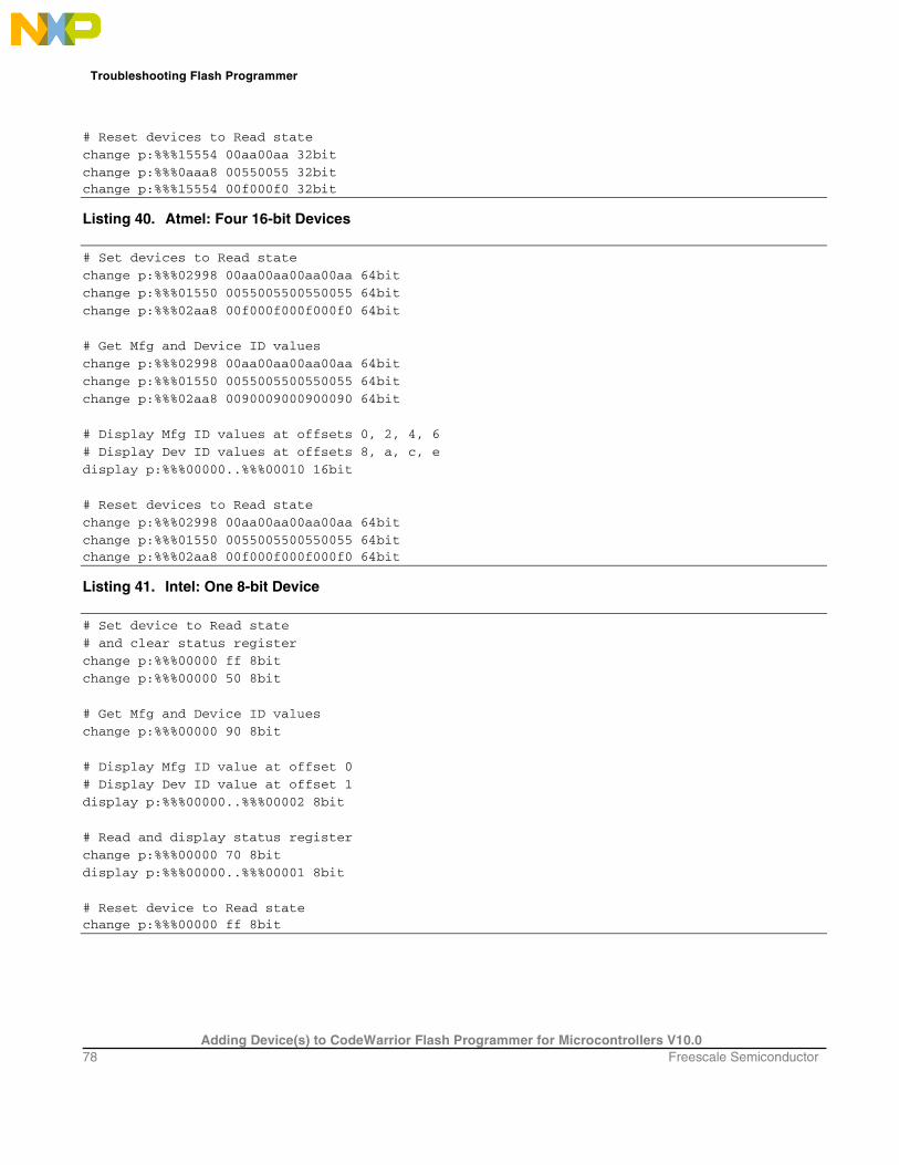
Troubleshooting Flash Programmer
Adding Device(s) to CodeWarrior Flash Programmer for Microcontrollers V10.0 78 Freescale Semiconductor
# Reset devices to Read state
change p:%%%15554 00aa00aa 32bit
change p:%%%0aaa8 00550055 32bit change p:%%%15554 00f000f0 32bit
Listing 40. Atmel: Four 16-bit Devices
# Set devices to Read state
change p:%%%02998 00aa00aa00aa00aa 64bit
change p:%%%01550 0055005500550055 64bit
change p:%%%02aa8 00f000f000f000f0 64bit
# Get Mfg and Device ID values
change p:%%%02998 00aa00aa00aa00aa 64bit
change p:%%%01550 0055005500550055 64bit
change p:%%%02aa8 0090009000900090 64bit
# Display Mfg ID values at offsets 0, 2, 4, 6
# Display Dev ID values at offsets 8, a, c, e
display p:%%%00000..%%%00010 16bit
# Reset devices to Read state
change p:%%%02998 00aa00aa00aa00aa 64bit
change p:%%%01550 0055005500550055 64bit change p:%%%02aa8 00f000f000f000f0 64bit
Listing 41. Intel: One 8-bit Device
# Set device to Read state
# and clear status register
change p:%%%00000 ff 8bit
change p:%%%00000 50 8bit
# Get Mfg and Device ID values
change p:%%%00000 90 8bit
# Display Mfg ID value at offset 0
# Display Dev ID value at offset 1
display p:%%%00000..%%%00002 8bit
# Read and display status register
change p:%%%00000 70 8bit
display p:%%%00000..%%%00001 8bit
# Reset device to Read state change p:%%%00000 ff 8bit

Troubleshooting Flash Programmer
Adding Device(s) to CodeWarrior Flash Programmer for Microcontrollers V10.0 Freescale Semiconductor 79
Listing 42. Intel: Two 8-bit Devices
# Set devices to Read state
# and clear status registers
change p:%%%00000 ffff 16bit
change p:%%%00000 5050 16bit
# Get Mfg and Device ID values
change p:%%%00000 9090 16bit
# Display Mfg ID values at offsets 0, 1
# Display Dev ID values at offsets 2, 3
display p:%%%00000..%%%00004 8bit
# Read and display status registers
change p:%%%00000 7070 16bit
display p:%%%00000..%%%00002 8bit
# Reset devices to Read state change p:%%%00000 ffff 16bit
Listing 43. Intel: Four 8-bit Devices
# Set devices to Read state
# and clear status registers
change p:%%%00000 ffffffff 32bit
change p:%%%00000 50505050 32bit
# Get Mfg and Device ID values
change p:%%%00000 90909090 32bit
# Display Mfg ID values at offsets 0, 1, 2, 3
# Display Dev ID values at offsets 4, 5, 6, 7
display p:%%%00000..%%%00008 8bit
# Read and display status registers
change p:%%%00000 70707070 32bit
display p:%%%00000..%%%00004 8bit
# Reset devices to Read state change p:%%%00000 ffffffff 32bit
Listing 44. Intel: One 16-bit Device
# Set device to Read state
# and clear status register
change p:%%%00000 ffff 16bit
change p:%%%00000 5050 16bit
# Get Mfg and Device ID values
change p:%%%00000 9090 16bit

Troubleshooting Flash Programmer
Adding Device(s) to CodeWarrior Flash Programmer for Microcontrollers V10.0 80 Freescale Semiconductor
# Display Mfg ID value at offset 0
# Display Dev ID value at offset 2
display p:%%%00000..%%%00004 16bit
# Read and display status register
change p:%%%00000 7070 16bit
display p:%%%00000..%%%00002 16bit
# Reset device to Read state change p:%%%00000 ffff 16bit
Listing 45. Intel: Two 16-bit Devices
# Set devices to Read state
# and clear status registers
change p:%%%00000 ffffffff 32bit
change p:%%%00000 50505050 32bit
# Get Mfg and Device ID values
change p:%%%00000 90909090 32bit
# Display Mfg ID values at offsets 0, 2
# Display Dev ID values at offsets 4, 6
display p:%%%00000..%%%00007 16bit
# Read and display status registers
change p:%%%00000 70707070 32bit
display p:%%%00000..%%%00003 16bit
# Reset devices to Read state change p:%%%00000 ffffffff 32bit
Listing 46. Intel: Four 16-bit Devices
# Set devices to Read state
# and clear status registers
change p:%%%00000 ffffffffffffffff 64bit
change p:%%%00000 5050505050505050 64bit
# Get Mfg and Device ID values
change p:%%%00000 9090909090909090 64bit
# Display Mfg ID values at offsets 0, 2, 4, 6
# Display Dev ID values at offsets 8, a, c, e
display p:%%%00000..%%%00008 16bit
# Read and display status registers
change p:%%%00000 7070707070707070 64bit
display p:%%%00000..%%%00004 16bit

Troubleshooting Flash Programmer
Adding Device(s) to CodeWarrior Flash Programmer for Microcontrollers V10.0 Freescale Semiconductor 81
# Reset devices to Read state change p:%%%00000 ffffffffffffffff 64bit
10.7. Examples Following are example flash interrogations that are common for some target boards that use both AMD and Intel devices.
10.7.1. One 16 bit AMD Device
Freescale derivatives M5208EVBE, M52277EVB, M5282EVB, and M5235EVB all use AMD 16x1 devices. These devices have Manufacturer ID 0x01. The commands have been executed on the M5235EVB board. Perform these steps for one 16 bit AMD device:
1. Copy the code in Listing 32 into the text file check_flash.tcl, making the code a script.
2. Substitute the string FFE with all instances of %%%.
3. Use the source command to invoke the script. Listing 47 shows the resulting code.
NOTE The comment lines in Listing 47 and Listing 48 are for clarification. The CodeWarrior source command discards comment lines, so you will not see such comments in the Debugger Shell view.
Listing 47. Example one results
# Set device to Read state
change p:FFE00000 f0f0 16bit
# Get Mfg and Device ID values
change p:FFE00aaa aaaa 16bit
change p:FFE00554 5555 16bit
change p:FFE00aaa 9090 16bit
# Display Mfg ID value at offset 0
# Display Dev ID value at offset 2
display p:FFE00000..%%%00004 16bit
ffe00000 $0001 $2245 $0000 .. "E ..
# Reset device to Read state change p:FFE00000 f0f0 16bit

Troubleshooting Flash Programmer
Adding Device(s) to CodeWarrior Flash Programmer for Microcontrollers V10.0 82 Freescale Semiconductor
The result shows that the manufacturer ID code for the device is 0x1 and the device ID code is 0x2245. This confirms basic read/write functionality of the flash device.
10.7.2. One 16 bit Intel Device
Freescale derivatives M5329EVBE, M5373EVB, M5475EVB, and M5485EVB all use Intel 16x1 devices. These devices have Manufacturer ID 0x89. The commands have been executed on a M5329EVBE board.. Perform these steps for one 16 bit Intel device,:
1. Copy the code in Listing 44 into text file check_flash.tcl, making the code a script.
2. Substitute the string 000 with all instances of %%%.
3. Use the source command to invoke the script. Listing 48 shows the resulting code.
Listing 48. Example Two Results
# Set device to Read state
# and clear status register
change p:00000000 ffff 16bit
change p:00000000 5050 16bit
# Get Mfg and Device ID values
change p:00000000 9090 16bit
# Display Mfg ID value at offset 0
# Display Dev ID value at offset 2
display p:00000000..%%%00004 16bit
0 $0089 $88C3 $0001 .. .. .. # Read and display status register
change p:00000000 7070 16bit
display p:00000000..%%%00002 16bit
0 $0080 $0080 .. ..
# Reset device to Read state change p:00000000 ffff 16bit
The result shows that the manufacturer ID code is 0x0089 and the device ID code is 0x88C3. This confirms basic read/write functionality of the flash device.

Troubleshooting Flash Programmer
Adding Device(s) to CodeWarrior Flash Programmer for Microcontrollers V10.0 Freescale Semiconductor 83
10.8. Summary For most flash devices in use today, programming involves state machine like cycles of multiple writes that must proceed the final write cycle. To diagnose flash programming failures, you must determine whether the cause of the failure is in target hardware or flash programming software. The general method of document lets you make this determination through simple, low level writes and reads, without the use of expensive and complicated logic analyzers. If these reads and writes fail, the problem most likely is on the target. If these reads and writes succeed, the problem most likely is in the flash programming software, so please contact Technical Support at http://www.freescale.com/support.

How to Reach Us :
Home Page: www.freescale.com
E-mail: [email protected]
USA/Europe or Loca tions Not Lis te d : Freescale Semiconductor Technical Information Center, CH370 1300 N. Alma School Road Chandler, Arizona 85224 +1-800-521-6274 or +1-480-768-2130 [email protected]
Europe , Midd le Eas t, and Africa : Freescale Halbleiter Deutschland GmbH Technical Information Center Schatzbogen 7 81829 Muenchen, Germany +44 1296 380 456 (English) +46 8 52200080 (English) +49 89 92103 559 (German) +33 1 69 35 48 48 (French) [email protected]
J apan: Freescale Semiconductor Japan Ltd. Headquarters ARCO Tower 15F 1-8-1, Shimo-Meguro, Meguro-ku, Tokyo 153-0064, Japan 0120 191014 or +81 3 5437 9125 [email protected]
As ia /P acific : Freescale Semiconductor Hong Kong Ltd. Technical Information Center 2 Dai King Street Tai Po Industrial Estate Tai Po, N.T., Hong Kong +800 2666 8080 [email protected]
Document Number: AN3859 21 September 2011
Information in this document is provided solely to enable system and software implementers to use Freescale Semiconductor products. There are no express or implied copyright licenses granted hereunder to design or fabricate any integrated circuits or integrated circuits based on the information in this document. Freescale Semiconductor reserves the right to make changes without further notice to any products herein. Freescale Semiconductor makes no warranty, representation or guarantee regarding the suitability of its products for any particular purpose, nor does Freescale Semiconductor assume any liability arising out of the application or use of any product or circuit, and specifically disclaims any and all liability, including without limitation consequential or incidental damages. “Typical” parameters that may be provided in Freescale Semiconductor data sheets and/or specifications can and do vary in different applications and actual performance may vary over time. All operating parameters, including “Typicals”, must be validated for each customer application by customer’s technical experts. Freescale Semiconductor does not convey any license under its patent rights nor the rights of others. Freescale Semiconductor products are not designed, intended, or authorized for use as components in systems intended for surgical implant into the body, or other applications intended to support or sustain life, or for any other application in which the failure of the Freescale Semiconductor product could create a situation where personal injury or death may occur. Should Buyer purchase or use Freescale Semiconductor products for any such unintended or unauthorized application, Buyer shall indemnify and hold Freescale Semiconductor and its officers, employees, subsidiaries, affiliates, and distributors harmless against all claims, costs, damages, and expenses, and reasonable attorney fees arising out of, directly or indirectly, any claim of personal injury or death associated with such unintended or unauthorized use, even if such claim alleges that Freescale Semiconductor was negligent regarding the design or manufacture of the part. Freescale, the Freescale logo, CodeWarrior and ColdFire are trademarks of Freescale Semiconductor, Inc., Reg. U.S. Pat. & Tm. Off. ColdFire+, Kinetis, Processor Expert, and Qorivva are trademarks of Freescale Semiconductor, Inc. All other product or service names are the property of their respective owners. ARM is the registered trademark of ARM Limited. The Power Architecture and Power.org word marks and the Power and Power.org logos and related marks are trademarks and service marks licensed by Power.org.
© Freescale Semiconductor, Inc. 2009-2010. All rights. .


