Embed Size (px)
Citation preview

AN1067/DRev. 1, 5/2002
Pulse Generation and Detection with Microcontroller Units
Application Note
F
ree
sca
le S
em
ico
nd
uc
tor,
I
nc
...
By Mike Pauwels
Introduction
This application note examines two common interfaces between microcontroller units (MCUs) and external circuitry:
• Pulse generation• Pulse detection
Several families of Freescale MCUs and a variety of pulse applications are considered. Code segments and listings are also included.
Pulse Generation
MCUs are often required to generate timed output pulses (i.e., signals asserted for a specified period of time). The application can be strobing a display latch, transmitting a code, or metering a reagent in a process control system. However, each application has specific requirements for pulse duration and accuracy. This application note examines methods of generating these pulses in relationship to timing accuracy, coding efficiency, and other controller requirements.
The following paragraphs describe the timing of the signals (start time and duration of the pulse). All pulses can be divided into three basic classifications:
• Short pulses• Long pulses• Easy pulses
Each class of pulse is considered using three MCUs with different timer structures.
On the low end of the scale is the MC68HC05J1. The simple timer in this device limits the accuracy of short pulses and requires a larger amount of software investment to produce a given pulse. The second MCU, the MC68HC705C8 and similar devices, has a 16-bit timer that is somewhat more powerful and
For More Information On This Product,
Go to: www.freescale.com

AN1067/D
F
ree
sca
le S
em
ico
nd
uc
tor,
I
Freescale Semiconductor, Inc.n
c..
.
flexible than the MC68HC05J1 timer. Finally, the MC68HC11A8 offers additional features in the 16-bit timer system, as well as the possibility of producing multiple pulses simultaneously.
Because time measurements are being considered, the clock frequency for the MCU is significant. For this discussion, each MCU is assumed to be operating at 2.0 MHz internal, implying a 4.0 MHz crystal for the M68HC05 and an 8.0 MHz crystal for the MC68HC11A8. The maximum speeds of these devices is somewhat higher, but these are commonly used values. Of course, these MCUs can all be operated at much slower clock speeds. All times should be scaled to the actual clock frequency.
Short Pulses The classification of short pulses may vary according to the accuracy of the required pulse and the available MCU resources. In general, pulses of a few tens of microseconds and longer are relatively easy to produce. Below this broad limit, the methods used to generate short pulses may vary greatly according to the specific requirements. To produce a strobe pulse whose minimum required duration is in the order of magnitude of the clock period only requires writing a port bit high, then low in consecutive operations.
PULSE BSET BIT0,PORTABCLR BIT0,PORTA
This produces a pulse duration of 2.5 µs in the M68HC05, and 3.0 µs in the MC68HC11A8. The longer time in the MC68HC11A8 is a consequence of a longer BSET/BCLR instruction formation — three bytes versus two bytes in the M68HC05. This is compensated for by the ability to set and clear multiple bits in one instruction. However, the MC68HC11A8 provides for a 0.5 µs minimum pulse by using the resources of two timer compare registers.
If the requirement for the pulse is longer than 2 µs, the above pair of instructions can be separated by no operation (NOP) instructions or even by useful instructions to stretch to the desired pulse width. There are two problems with this option. First, padding the instructions with NOPs consumes MCU resources. If there is some task that the MCU can accomplish between the set and clear, this is not too serious. More difficult is the possible requirement that the pulse duration be run time variable. The flexibility of the busy wire pulse timing can be extended by adding a loop.
SETUP LDA DURATIONPULSE BSET BIT0,PORTALOOP DECA
BNE LOOPBCLAR BIT0,PORTA
2 Pulse Generation and Detection with Microcontroller Units
For More Information On This Product, Go to: www.freescale.com
AN1067/DPulse Generation
F
ree
sca
le S
em
ico
nd
uc
tor,
I
Freescale Semiconductor, Inc.n
c..
.
The duration of the pulse is:2.5 + 3.8 * DURATION µs for the M68HC05
and3.0 + 2.5 * DURATION µs for the MC68HC11A8
Of course the previous code could be padded with any number of NOPs at 1.0 µs or with branch never (BRNs) at 1.5 µs either inside or outside the timing loop for more precise values. However, the variable resolution is 2.5 or 3.0 µs
NOTE: In these cases, the on-board timers were not used. In the case of these short pulses, the overhead of setting up and reading the timers would be about as long as the pulse being driven. When the required pulse width is long enough to use the timer, easy pulses are produced.
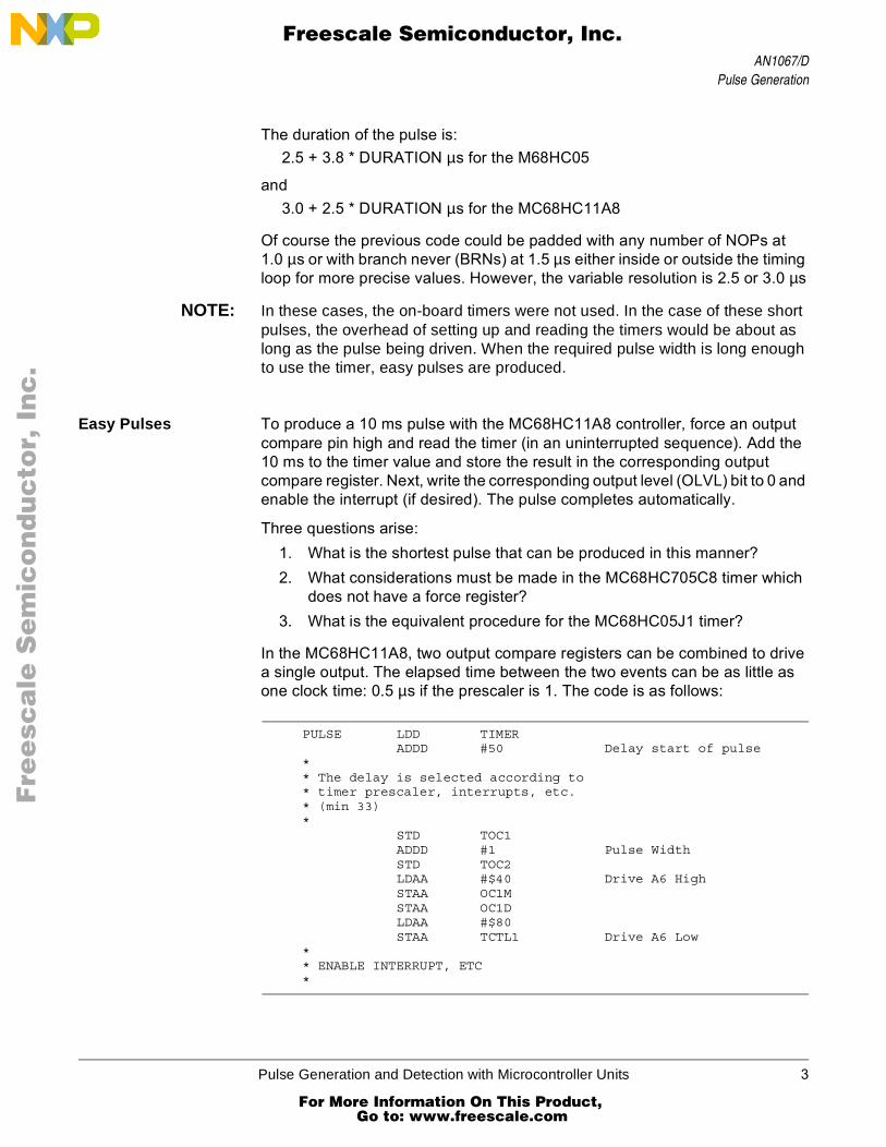
Easy Pulses To produce a 10 ms pulse with the MC68HC11A8 controller, force an output compare pin high and read the timer (in an uninterrupted sequence). Add the 10 ms to the timer value and store the result in the corresponding output compare register. Next, write the corresponding output level (OLVL) bit to 0 and enable the interrupt (if desired). The pulse completes automatically.
Three questions arise:1. What is the shortest pulse that can be produced in this manner?2. What considerations must be made in the MC68HC705C8 timer which
does not have a force register?3. What is the equivalent procedure for the MC68HC05J1 timer?
In the MC68HC11A8, two output compare registers can be combined to drive a single output. The elapsed time between the two events can be as little as one clock time: 0.5 µs if the prescaler is 1. The code is as follows:
PULSE LDD TIMERADDD #50 Delay start of pulse
** The delay is selected according to* timer prescaler, interrupts, etc.* (min 33)*
STD TOC1ADDD #1 Pulse WidthSTD TOC2LDAA #$40 Drive A6 HighSTAA OC1MSTAA OC1DLDAA #$80STAA TCTL1 Drive A6 Low
** ENABLE INTERRUPT, ETC*
Pulse Generation and Detection with Microcontroller Units 3
For More Information On This Product, Go to: www.freescale.com

AN1067/D
F
ree
sca
le S
em
ico
nd
uc
tor,
I
Freescale Semiconductor, Inc.n
c..
.
With the MC68HC705C8 timer system, there is no force bit for compare. The only way to drive the timer compare (TCMP) line high is to set the OLVL bit in the timer control register (TCR) and wait for a match. The exact start time of the pulse is easily obtained from the output compare register (OCR), so pulse accuracy is unaffected for moderate pulses. Often the pulse is started as soon as possible, if for no other reason than to complete the pulse setup routine. The following code segment provides a pulse start in 12 µs, assuming no interrupts.
** START THE PULSE*
BSET OLVL,TCR* OUTPUT_COMPARE: = TIMER + DELAY
LDX ACHR MUST BE READ FIRSTLDA ACLR TIMER = X:AADD $DELAYBCC OC1 MARK TIMEINCX
OC1 STX OCHR INHIBITS TOCSTA OCLR ENABLES TOC
** IF DELAY IS CORRECT, PULSE WILL* TURN ON IMMEDIATELY
Using a value for DELAY of about 21 (cycles) results in an average latency of 12 µs after the beginning of this routine.
NOTE: Loads and stores to the 16-bit registers are always performed high byte first to take advantage of special hardware that maintains coherency in 16-bit data transfers. The pulse will turn on 1 µs later when there is a carry out of the low byte add, which should occur about 1 in 12 times.
The programing of a moderate length pulse is now quite trivial. Simply add the desired pulse width (at 2 µs per bit) to the value stored in the output compare. Write a new value to the OCR and set the OLVL bit to 0. The following is used to finish code segment.
*WAIT FOR PULSE TO BE SETHERE BRCLR OCF,TSR,HERE
LDA PW_L PULSE WIDTH LS BYTEADD OCLRTAX TEMPORARILYLDA PW_H PULSE WIDTH MS BYTEADC OCHR INCLUDES CARRYSTA OCHR INHIBITS TOCSTX OCLR
**DONE!
The interrupt structure is not required to generate pulses. The 16-bit timers on the MC68HC11A8 and the MC68HC705C8 will automatically drive the falling edge of these pulses without software intervention. On the MC68HC05J1,
4 Pulse Generation and Detection with Microcontroller Units
For More Information On This Product, Go to: www.freescale.com

AN1067/DPulse Generation
F
ree
sca
le S
em
ico
nd
uc
tor,
I
Freescale Semiconductor, Inc.n
c..
.
there is no hardware timer interface. To drive moderate length pulses with this device, employ the interrupts so that useful work can be performed while the pulse is being timed. Consider a 10 ms pulse using the MC68HC05J1.
The simple timer of the MC68HC05J1 provides only the capability of being interrupted periodically. The source of interrupt can be a timer overflow or a real-time interrupt (RTI). The choice of interrupt times is given in Table 1.
Consider the algorithm for the timing of a pulse as counting “ticks” on a clock. Initially, it seems the ticks of the timer must be counted — 5,000 ticks (2 µs per tick) for the desired period of 10 ms. However, the timer overflow and real-time interrupts of the MC68HC05J1 provide long ticks that sound their completion with interrupts. Instead of 5,000 short ticks, count as follows:
1 RTI tick of 8,192 µs = 8,1923 TOF ticks at 512 µs = 1,536544 cycles of 0.5 µs = 272
----------TOTAL 10,000
= 10.000 ms
For most of this time background tasks can continue processing. The 544 cycles of busy-wait time include necessary work to set up the pulses. The key problem is the required timing of the start of the pulse. If the start time is flexible the design of the pulse could follow the pattern of Figure 1.
Figure 1. Time Line for a 10 ms Pulse with Flexible Start Time
Table 1. RTI and COP Rates (fOP = 2 MHz)
RT1/RT0 RTI COP
0 0 8.2 ms 57.3 ms
0 1 16.4 ms 114.7 ms
1 0 32.8 ms 229.4 ms
1 1 65.5 ms 458.8 ms
START PULSE STOP PULSE
VARIABLE DELAY < 8.192 ms
RTI
8.192 ms
TOF TOFTOF
BUSY WAIT
512 µs512 µs
272 µs
512 µs
10 ms
Pulse Generation and Detection with Microcontroller Units 5
For More Information On This Product, Go to: www.freescale.com

AN1067/D
F
ree
sca
le S
em
ico
nd
uc
tor,
I
Freescale Semiconductor, Inc.n
c..
.
Start the pulse on the next RTI service routine, then count timer overflow flags (TOFs) after the next RTI until the final sequence, which is timed by a busy-wait counter. Careful calculation of the latencies and instruction cycles produces a pulse with a high degree of accuracy.
When the start time is not as flexible, a different approach is necessary. Since it is now impossible to align the RTI boundaries with the pulse, use only the TOF ticks to time the pulse. To turn the pulse on as soon as possible, read the value of the timer at turn on. Calculate the time until the next overflow, add the predicted turn off execution time, and then determine how many full TOF periods are in the remainder. After subtracting these long ticks, the remaining value is the busy wait. A time line for this approach is given in Figure 2.
Figure 2. Time Line for a 10 ms Pulse with Flexible Start Time
Since an interrupt occurs every 512 µs, the performance of the MCU degrades slightly — about 10% versus 1% for the first approach. The following code yields a 10.0 ms pulse on port A1, with a latency of 2.5 µs after the code is entered.
* ASSUME THE DESIRED PULSE WIDTH,* RESOLVED TO 2 µs PER BIT,* IS STORED IN A TWO-BYTE LOCATION* LABELED: PW_H:PW_L. FOR A* PULSE WIDTH OF 10 ms THIS* VALUE WOULD BE $1388
* TURN ON THE PULSE
START BCLR TOF,TCSRLDA TIMERBSET BIT0,PORTACOMA = TIME REMAININGSBA PW_L LOW BYTE OF PULSEBCC PW1DEC PW_H BORROW 1
START PULSE STOP PULSE
VARIABLE DELAY = D < 5.12 µs
TOFTOFTOF
BUSY WAIT = 784 µs-D
10 ms
PULSEREQUIRED
START PULSE
512 µs x 18 = 9.216 ms
TOF TOF TOF TOF TOF TOF TOF TOF TOF TOF TOF TOF TOF TOF TOF TOF
6 Pulse Generation and Detection with Microcontroller Units
For More Information On This Product, Go to: www.freescale.com

AN1067/DPulse Generation
F
ree
sca
le S
em
ico
nd
uc
tor,
I
Freescale Semiconductor, Inc.n
c..
.
PW1 LDX #$AAMUL RE-SCALE LOW BYTE TOSTX PW_L ... 3 µs PER BITBSET TOFE,TCSRCLI
** THE TIMER INTERRUPT DOES THE REST* OF THE WORK:*TOFI DEC PW_H
BNE END_TLDA PW_LBEQ PLS_L
LOOP DECABNE LOOP
PLS_L BCLR BIT0,PORTAEND_T RTI
There will be some small inaccuracies due to latency of the interrupt and border conditions for the pulse width. The pulse can be refined, but if one-clock precision is required, choose another processor.
Long Pulses The idea of using the interrupt structure to count long “ticks” can be expanded beyond one byte. If a two-byte decrement is performed in the previous MC68HC05J1 example, pulses up to 30 seconds in length can be generated. The inaccuracies are the same in absolute terms as for the shorter pulses; therefore, the percent of error is much smaller.
The same approach is used to expand the pulse width that can be generated by the 16-bit timers in the MC68HC705C8 and the MC68HC11A8 processors. With the help of the output compare function, one-tick accuracy with very long pulses is possible. The accuracy of the output is determined only by the accuracy of the crystal. The code listed in Appendix A — TTL Long Pulse Generation has been tested in an MC68HC05C4 and produced pulses in the order of one minute with an accuracy of one part per million. Code to generate long pulses with an MC68HC11A8 is similar. Since the timer interrupts are used to count the ticks, most of the MCU resources are available to do background tasks. For example, the timer interrupt routine consumes less than 25 µs every 131 ms. This represents about 0.2% of the processing power of the MCU. The actual code takes about 200 bytes of memory. The pulse will be precise if the interrupts are not masked for more than about 130 ms at a time. Beyond the limit, whole ticks of 131 ms will be added.
Finally, the MC68HC11A8 timer system provides for two timer output functions to drive a single pin. With this MCU, the start time and end time of the pulse can be driven independently with differences of as little as one count between the two pulse edges.
Pulse Generation and Detection with Microcontroller Units 7
For More Information On This Product, Go to: www.freescale.com

AN1067/D
F
ree
sca
le S
em
ico
nd
uc
tor,
I
Freescale Semiconductor, Inc.n
c..
.
Summary of Pulse Generation
Many MCU systems interface to hardware systems by means of timed pulses. Modern MCUs handle these pulses in three different ways depending on the hardware timing structure available and the length of the pulse.
Short pulses, ranging in length from as short as a microsecond to a few tens of microseconds, are usually timed with “busy wait” loops. There is simply not enough time to set up a peripheral to control a pulse of short duration. The accuracy and resolution of these pulses is determined in part by the discrete execution time of branch instructions in the controller. The M68HC11 can drive a pulse as short as a microsecond, resolved to a microsecond, by using the resources of two timer compare registers.
Moderate length pulses are simple to drive automatically using the 16-bit timer available in the MC68HC11A8 and many of the M68HC05 MCUs. These are set-and-forget systems that run to completion typically in 131 ms. In the simpler M68HC05 MCUs, there is no 16-bit timer, and the moderate length pulses must use the timer overflow interrupt to count out large chunks of the pulse time while some background task is being performed.
The approach is similar in MCUs with the 16-bit timer when the desired pulse is greater than 131 ms. Multiple timer overflows can be counted in a few memory locations to produce very long pulses.
For more complex timing functions, a system may require a separate timing processor. In some complex control applications, an MC68HC11A8 or an M68HC05 is employed as a peripheral timer to a larger computational engine. A variation of this theme is the time processing unit (TPU) in the MC68332. This complex timing system can perform several different functions on 16 different channels simultaneously, independent of the main processor. Information on the MC68332 is available from your Freescale Sales Office.
Pulse Detection
Another system problem encountered when applying an MCU to a physical system is the detection and measurement of pulses. These can range from the actuation of a push button to pulse codes detection, detection of the period of rotation of an engine, and accumulation of the ‘on’ time of a process control valve. The periods can range from microseconds to minutes, hours, or more.
There are several parameters that characterize a pulse, as Figure 3 illustrates. As far as a digital system is concerned, most of these parameters cannot be measured directly by a digital device such as an MCU. Indeed, some parameters such as the voltage level must be modified before the pulse is applied to the MCU. If the values of these parameters are interesting to the system, then an external device such as an analog-to-digital converter is required. Other parameters may not be measurable by the MCU, including the signal rise and fall times and the presence of noise on the signal.
8 Pulse Generation and Detection with Microcontroller Units
For More Information On This Product, Go to: www.freescale.com

AN1067/DPulse Detection
F
ree
sca
le S
em
ico
nd
uc
tor,
I
Freescale Semiconductor, Inc.n
c..
.
Figure 3. Characteristics of a Pulse
Digital pulses convey information only in the timing of their signals, assuming that all voltage signals vary between VSS and VDD, and that rise and fall times are sufficiently fast to be unambiguous to the processor. The parameters of interest are the start time and duration of the pulse. Noise, if it exists, is interesting only to the extent that it can be seen by the controller, and in that case, provision must be made to reduce its effects.
There remains one significant question to address before software design can commence. What is the expected duration range of the pulse? There are no effective maximum limits on the duration which can be measured; but very short pulses may require the support of on-chip or off-chip hardware. A related characteristic is the start time of the pulse, measured from some reference. This can be thought of as the measurement of a pulse off time, and hence is not significantly different from the duration measurement. Also important is the required accuracy of the measurement, specified in absolute or relative terms.
One important choice the designer makes in addressing system problems is the type of MCU that will be used. Most MCUs have some sort of timing device on chip. Within the five basic families of Freescale processors are several timer variations. These range from the simple counter in theMC68HC05J1 to the sophisticated TPU of the MC68332. The former is useful only for the simplest requirements, while the latter can measure pulses accurately without intervention of the CPU.The choice of most applications is usually between an M68HC11 and one of the large family of M68HC05 devices.
VHigh
VLow
tRise tFall
PULSE DELAY
PULSE WIDTH
Pulse Generation and Detection with Microcontroller Units 9
For More Information On This Product, Go to: www.freescale.com

AN1067/D
F
ree
sca
le S
em
ico
nd
uc
tor,
I
Freescale Semiconductor, Inc.n
c..
.
The timer on the MC68HC11A8 provides as many as four hardware input signals with several hardware registers to measure input events. By combining two input capture functions, or by using the clock gate input of the MC68HC11A8, many pulse measurement problems are easily solved. It is more difficult to address the problems with the 16-bit timer system found on the most popular MCU family, the M68HC05.
Consider the accuracy limitations of the MC68HC(7)05Cx 16-bit timer. The timer counter itself is incremented once for every eight cycles of the MCU crystal frequency. A 4.0-MHz crystal provides a count resolution of 2 µs. With short pulses, this resolution may be a contributor to accuracy limitations. For example, measuring a 50 µs pulse, this resolution will produce a count of 25 with a 1-bit quantizing error, an uncertainty of 4%. However, in measuring a one minute pulse, the quantizing error is 0.0000033%,
In the case of the longer pulses, the accuracy of the crystal can contribute far more to the loss of precision. A limited sampling of clock frequencies on M68HC05 evaluation modules indicates that typical crystals may produce errors of 0.001%. While crystals can be selected or trimmed to much higher accuracy, it is important not to specify accuracies from the software that cannot be supported by the hardware.
Consider four general classes of pulses to detect:1. Very fast pulse, say 20 µs or less2. Longer pulses up to 130 ms3. Long pulses4. Noisy pulses
The second class is almost trivial with the TCAP feature of the M68HC05. Indeed, these are the most common class of pulses, and the hardware does almost all of the work. These are considered a special case of the third class of pulses. The other three classes require a bit more study.
Short Pulses To measure very fast pulses with the M68HC05, it is necessary to deal with the interrupt latency which can be as much as 10 µs. If an IRQ is triggered on the start of the pulse, the pulse may have ended by the time code is executed in the interrupt routine. Accuracy is limited by the latency of the system. An example of the code necessary to measure these pulses is given below.
INTRUPT:CLRABIL END_PULS
T_LOOP: INCA COUNT LOOPSA: BIH T_LOOP
END_PULS .* .*
10 Pulse Generation and Detection with Microcontroller Units
For More Information On This Product, Go to: www.freescale.com

AN1067/DPulse Detection
F
ree
sca
le S
em
ico
nd
uc
tor,
I
Freescale Semiconductor, Inc.n
c..
.
After the pulse is driven low on the IRQ line, the timed wait is executed for the rising edge which enables detection of a very short pulse. At END_PULS, the accumulator has a measurement of the length of the pulse resolve to 3 µs per bit. Assuming the interrupts are not masked the worst case time to get to point A the first time is 13.4 µs (11.5 µs if MUL is not used in the background). The fastest time is 9 µs. Any pulse shorter than this will result in a zero time value. If the pulse value is greater than zero, the pulse width is 3 µs times the accumulator value plus a latency time of 9–13.5 µs. Finally, the longest pulse time that this routine can reasonably measure before the accumulator will overflow is about 770 µs. The interpretation of the result is left to the user.
If a short pulse is brought in on the TCAP line, there is additional latency to consider. If there is sufficient time to reverse the IEDG bit and clear the ICF (minimum about 20 µs), this is a class 2 pulse. If the pulse is shorter than this, the input capture function may miss the second edge. Unlike the MC68HC11A8 input capture functions, the M68HC05 timer pin (TCAP) is not directly detectable. Precautions must be taken in the hardware design if very short pulses are possible. For example, a port line could be wired to the TCAP pin and the state of the pin could be tested with a BRSET/BRCLR. The minimum resolvable pulse length is still no better than the IRQ driven case. However, using the TCAP input offers capability to measure pulses of either polarity up to 131 ms in length and with a resolution of 2 µs.
Of course, if the pulse is expected to be short and the start time can be predicted, a busy wait can be executed for both ends of the pulse. In this case it is necessary to continually test the state of the input pin and branch accordingly. For example, if the expected pulse length is between 5 µs and 100 µs, execute a string of tests as shown below.
PULSE:CLRA
PO BRCLR PIN,PORT,P0 WAIT FOR THE FIRST EDGEBRSET PIN,PORT,P1 ACTUALLY USING THE CODE TO
MEASUREBRSET PIN,PORT,P2...BRSET PIN,PORT,PNINCA
PN INCA...
P2 INCAP1 INCA** ACC CONTAINS PULSE WIDTH OF 2.5 µs* PER BIT
Pulse Generation and Detection with Microcontroller Units 11
For More Information On This Product, Go to: www.freescale.com

AN1067/D
F
ree
sca
le S
em
ico
nd
uc
tor,
I
Freescale Semiconductor, Inc.n
c..
.
This code yields a resolution of 2.5 µs for any pulse down to 2.5 µs. Below that, the pulse may be missed. As the expected pulse length gets larger, this code becomes unwieldy and finally impossible.
The addition of an instruction loop shortens the code at the expense of resolution.
PULSE:CLRA
PO BRCLR PIN,PORT,P0P1 INCA
BRSET PIN,PORT,P1** ACC CONTAINS PULSE AT 4 µs PER BIT*
For longer (class 2) pulses, use the input capture register of the timer to do all the work. Where the pulse is more than a few tens of microseconds long, the interrupt structure works well to measure the pulse within the accuracy of the crystal. The rising edge of the pulse triggers a first interrupt, and the service routine enables the interrupt on the falling edge. By reading the input capture register on each edge, the exact pulse length can be measured. This class of pulses is included in a special case of the long pulses shown below.
Longer Pulses What if the pulse length exceeds the rollover time of the timer? By counting the rollovers, a pulse of arbitrary length can be measured. Consider the possibility of a 60 second pulse that must be detected and measured accurately. If the timer counts 2 µs per bit, 30 million counts must be accumulated. To store this information, log2 (30,000,000,000) = 25 bits, or 4 bytes are needed. To be precise, a value of $1 C9 C3 80 is expected.
The 16-bit timer will automatically record the edges of the pulse. Ignoring the overflow, if the start time is subtracted from the end time the result will yield the two least significant bytes of the pulse width. In the 60 second example, if the pulse is exactly correct, the difference between the output compare value at the start of the pulse and the value at the end of the pulse will be $C380. Between those two pulse events, the timer will roll over $1C9 times (= 457). Counting those rollovers exactly will determine the pulse length. The timer overflow facility will allow a count of the rollovers under interrupt control. Some problems remain in arbitrating the interrupts and protecting for boundary conditions, which will be discussed below.
The general approach taken for the MC68HC05Cx TCAP works as well for the M68HC11 Family when a single input capture function is used for measurement.
Appendix B — Long Pulse Detection is a listing of an M68HC05 program which can measure very long pulses with single tick accuracy. The program
12 Pulse Generation and Detection with Microcontroller Units
For More Information On This Product, Go to: www.freescale.com

AN1067/DPulse Detection
F
ree
sca
le S
em
ico
nd
uc
tor,
I
Freescale Semiconductor, Inc.n
c..
.
was tested with the pulse generation problem listed above and appears to work within the accuracy of the crystal. Some adjustment may be necessary when this software is integrated into the user’s program, particularly insofar as the interrupt latency is affected, but the basic structure of the routines will perform the measurement function.
NOTE: Class 2 pulses can be measured with this routine as it stands, although some code savings can be realized if the pulse to be measured is known to be contained in less than four bytes.
Three particular areas should be attended to when incorporating this software in a larger project. The measurement routine uses mutually exclusive interrupts and no subroutines; therefore, its contribution to stack push is seven bytes. Add this to any other subroutine and interrupt stack usage to determine the maximum stack depth and therefore the available RAM.
If other interrupts are used, remember that the interrupt mask is automatically set when the interrupt routine is entered. If the mask cannot be cleared, the execution time of the other interrupt, plus its latency, must be kept somewhat less than 500 µs (or the pulse width, whichever is smaller) to preserve the accuracy of the measurement routine. The same is true if critical code sections must be preserved with SEI. . .CLI instructions.
Within these limitations, the automatic timing features of the TCAP will provide accurate measurement of the pulse. The 500 µs limitation is necessary to assure the correct handling of the boundary conditions when an overflow coincides with a pulse edge. If the interrupts must be masked for longer periods, the boundary conditions handling can be modified.
The third area to consider is the effect of the interrupts on execution speed of the processor. The pulse measurement routines take less than 0.02% of the clock cycles when measuring long pulses, so the routine will not significantly affect the throughput of most programs; however, each timer overflow interrupt takes about 24 µs, so software timing loops and critical sections can be affected.
Noisy Pulses The important thing to remember about noisy pulses is that a noise edge often cannot be distinguished from a pulse edge. This is particularly true when the input capture register is used to detect the edge. But even when the edge is polled, a momentary change in the signal level can be erroneously interpreted.
In general, it is difficult to measure any true pulse that contains noise pulse durations in order of magnitude of the measurement resolution. This means that signals must be free of 1 µs noise pulses for most MCU detection and measurement algorithms. The MC68HC11A8 pulse accumulator function in gated mode can be used to measure the total asserted time of a very noisy pulse.
Pulse Generation and Detection with Microcontroller Units 13
For More Information On This Product, Go to: www.freescale.com

AN1067/D
F
ree
sca
le S
em
ico
nd
uc
tor,
I
Freescale Semiconductor, Inc.n
c..
.
Often, the easiest way to eliminate the ambiguity of minor noise is with some low pass hardware filtering. Remember that low pass filtering will also round and delay the edges of the pulse. The delay will contribute more or less to the accuracy of the measurement. In addition, sampled edges can be double checked in our busy wait algorithms with the addition of a single instruction per edge.
PULSE:CLRA
P0 BRCLR PIN,PORT,P0BRCLR PIN,PORT,P0
P1 INCABRSET PIN,PORT,P1BRSET PIN,PORT,P1
** ACC HAS PULSE AT 6.5 µs PER BIT
Sophisticated digital filter algorithms can be used to extract a pulse from very noisy conditions, but these are beyond the scope of this application note. Consider a simple method of determining the approximate pulse width of an input signal corrupted by a lot of noise.
Consider the signal of Figure 4. Is this one noisy 5 ms pulse or a number of smaller pulses? Taken at face value, this would translate into a number of various length disjoint pulses. However, if this were part of a pulse width modulated code that had been transmitted on an r.f. carrier, the range of reception of the pulse could be significantly improved if the intelligence could be unambiguously extracted from this waveform. Much of the success of decoding algorithms depends on the knowledge of the expected signal. If, for example, the waveform is expected to be either a 6 ms pulse or a 2 ms pulse, it is expected that this algorithm would more often choose the former. If there were some independent cross checks on the validity of the code detection, such as a cyclic redundancy check, the detection could be made with a fair degree of certainty.
Figure 4. Noisy Pulse
14 Pulse Generation and Detection with Microcontroller Units
For More Information On This Product, Go to: www.freescale.com

AN1067/DPulse Detection
F
ree
sca
le S
em
ico
nd
uc
tor,
I
Freescale Semiconductor, Inc.n
c..
.
It is beyond the scope of this application note to present a detailed discussion of pulse train encoding and decoding, but the following paragraphs offer a few ideas about developing an effective method for capturing noisy pulses with an MCU.
The detection of the above signal (Figure 4) with any of the earlier methods is unlikely to yield the correct data. With the MC68HC11A8 pulse accumulator, the pulse can be determined to be more likely 6 ms than 2 ms, but without the pulse accumulator, the M68HC05 MCUs require more software intensive methods.
The basic strategy used to measure the pulse is to take periodic samples of the signal and employ some heuristic process to discover the signal in the noise. Most commonly, the selected algorithm is simple voting. Additionally, some cross check of the data such as a check sum may be employed. If, for example, a 100 µs sample of the pulse shown in Figure 4 is taken, marked by the tick marks on the drawing, the findings show that the signal is high for 37 to 50 samples. This is more consistent with a wide pulse than a narrow one. If a cross check agrees with this conclusion, there is some confidence in the conclusion. If the cross check disagrees, the error could be guessed based on the lowest probability detection; or a re-transmission might be required. If no cross check is possible, a decision can be made on a minimum probability required to accept the data.
Below is a sample routine that uses the output compare interrupt to time the samples. Fifty samples are accumulated before testing the vote.
TOCI BRCLR TOF,TSR,NO_TOC CLEAR FLAGLDX OCHRLDA OCLRADD #50 INT IN 100BCC SMP1 ..µsINCX
SMP1 STX OCHRSTA OCLR
** NEXT SAMPLE IN 100 µs*
BRCLR PIN,PORT,SMP2INC VOTEBRA SMP3
SMP2 DEC VOTEDEC COUNTBNE SMP9
** HERE AFTER 50 SAMPLES* PUT VOTING ROUTINE HERE*NO_TOC:** DO OTHER INTERRUPT HERE*
RTI
Pulse Generation and Detection with Microcontroller Units 15
For More Information On This Product, Go to: www.freescale.com

AN1067/D
F
ree
sca
le S
em
ico
nd
uc
tor,
I
Freescale Semiconductor, Inc.n
c..
.
NOTE: This interrupt routine consumes only about 25–30% of the processor cycles. This number is directly related to the sample rate — sampling of 1/2 the rate reduces usage to less than 15% of the processor.
The choice of voting algorithm is application dependent. However, synchronization of the signal must also be considered. Depending on the type of coding used, a signal can be assumed to be self-synced. That is, the measurement of any pulse after a quiet period causes the receiving processor to try to wake up to a wide pulse or a narrow pulse. This causes the voting algorithm to reject pulses that vary widely from one of the expected widths.
With crystal controlled oscillators in both the transmitting processor and the receiving one, this does not present a problem. However, if one or both of the controller clocks is not tightly regulated the receiver will require time base as well as start time synchronization. In general, the more information that must be transmitted, the greater potential for error due to noise. The information transmitted is the code, the start time, and the time base.
Summary of Pulse Detection
MCU systems often read information from a hardware device by means of timed pulses. When these pulses fall in the range of a few tens of milliseconds, most MCUs can measure the pulse width easily with a high degree of accuracy. When the pulses are very short, very long, or noisy the accurate detection and measurement of them is more difficult.
The most important decision to be made in system design for pulse measurement is the choice of MCU, specifically the timer subsystem.The least sophisticated timers such as found on the MC68HC05J1 lose some resolution and accuracy, particularly for short pulses, but these simple timers are often found on the low cost chips. As the complexity and cost of the timer is increased, so is the performance of the MCU in this task. The very complex timer system in the MC68332 provides the greatest resolution and performance of any MCU available. For information, call your local Freescale Sales Office.
16 Pulse Generation and Detection with Microcontroller Units
For More Information On This Product, Go to: www.freescale.com

AN1067/DAppendix A — TTL Long Pulse Generation
F
ree
sca
le S
em
ico
nd
uc
tor,
I
Freescale Semiconductor, Inc.n
c..
.
Appendix A — TTL Long Pulse Generation
** TIC-T0C ROUTINES FOR 68HC05CX** WRITTEN 11/11/89 BY MIKE PAUWELS*** PULSE GENERATION** THIS ROUTINE GENERATES PULSES FROM A MC68HC05CX MICROCONTROLLER USING* THE TIMER OUTPUT COMPARE FUNCTION. THE LENGTH OF PULSES GENERATED* RANGE FROM A FEW MICROSECONDS TO MORE THAN TWO HOURS.** THIS SOFTWARE IS INTENDED AS A SUBSYSTEM TO BE INCLUDED IN A LARGER* PROGRAM. ETC.** CONSTANTS:* SYSTEM CONSTANTS:* ADDRESSES:
OPT nolPORTA EQU 0 PORT ADDRA EQU 4 DATA DIRECTION REGISTER FOR PORT ATCR EQU $12 TIMER CONTROL REGISTERICIE EQU 7 INPUT CAPTURE INTERRUPT ENABLEOCIE EQU 6 OUTPUT COMPARE INTERRUPT ENABLETOIE EQU 5 TIMER OVERFLOW INTERRUPT ENABLEIEDG EQU 1 INPUT EDGEOLVL EQU 0 OUTPUT LEVELTSR EQU $13 TIMER STATUS REGISTERICF EQU 7 INPUT CAPTURE FLAGOCF EQU 6 OUTPUT COMPARE FLAGTOF EQU 5 TIMER OVERFLOW FLAGICHR EQU $14 INPUT CAPTURE REGISTER HIGH BYTEICLR EQU $15 INPUT CAPTURE REGISTER LOW BYTEOCHR EQU $16 OUTPUT COMPARE REGISTER HIGH BYTEOCLR EQU $17 OUTPUT COMPARE REGISTER LOW BYTECHR EQU $18 TIMER/COUNTER HIGH BYTECLR EQU $19 TIMER/COUNTER LOW BYTEACHR EQU $1A ALTERNATE TIMER/COUNTER HIGH BYTEACLR EQU $1B ALTERNATE TIMER/COUNTER LOW BYTE
OPT 1* PROGRAM CONSTANTS
ORG $20DELAY FCB 6 DELAY FOR START OF PULSEMIN_PLS FCB 5 MINIMUM PULSE WIDTH IN CLOCK COUNTSDO_PLS FCB $01,$C9,$C3,$80* VARIABLES
ORG $BA OR CONCATENATE WITH USER MEMORYPULSE RMB 4 MAX TIME = 143.1655765 MINUTES!** ASSUMING A 4 MHz CRYSTAL, FOUR BYTES WILL AUTOMATICALLY TIME* 2^33 MICROSECONDS (ABOUT 2.4 HOURS) WITHIN THE ACCURACY OF THE* CRYSTAL. EACH BIT IS 2 MICROSECONDS. FOR LONG TIME PERIODS,* CONSIDER THAT A SLOWER CLOCK WILL SAVE POWER AND A 32 kHz WATCH* CRYSTAL IS INEXPENSIVE, BUT REMEMBER THAT THE PROCESSOR EXECUTION
Pulse Generation and Detection with Microcontroller Units 17
For More Information On This Product, Go to: www.freescale.com
AN1067/D
F
ree
sca
le S
em
ico
nd
uc
tor,
I
Freescale Semiconductor, Inc.n
c..
.
* WILL SLOW BY 122 TIMES! IF YOU HAVE A LOT OF PROCESSING TO DO* BETWEEN UPDATES, YOU MAY FIND THE PROCESSOR TOO SLOW!** SOME OTHER TIME OPTIONS:* 5 BYTES WILL TIME UP TO 25.45 DAYS* 6 BYTES WILL TIME UP TO 17.83 YEARS* 7 BYTES WILL TIME 4,566 YEARS!*** NO RESET INITIALIZATION IS REQUIRED. THE TIMED PULSE WILL BE* DRIVEN ON THE TCMP PIN WHICH IS AUTOMATICALLY INITIALIZED AS* AN OUTPUT. THE TIMER OUTPUT COMPARE AND THE TIMER OVERFLOW* INTERRUPTS ARE INITIALIZED BY THE START PULSE SUBROUTINE (STRT_PLS).*FLAGS RMB 1 STORE A FLAGFIRE EQU 7 INDICATES PULSE HAS STARTEDLAST EQU 6 INDICATES LAST INTERRUPT HAS OCCURED** MAIN PROGRAM GOES HERE. THE LENGTH OF THE DESIRED PULSE IS* DETERMINED AND STORED IN ‘PULSE’ AT 2 MICROSECONDS PER BIT.* THE PULSE WILL START AFTER ‘STRT_PLS’ IS CALLED WITH THE* LATENCY AND ACCURACY NOTED BELOW.
*********************************************************************************** RESET ROUTINE ***********************************************************************************
ORG $100RST_INT:
CLR TCRCLR FLAGS RESET ALL FLAGSLDA #$FFSTA DDRALDA #$02STA PORTA
*********************************************************************************** MAIN PROGRAM ***********************************************************************************
** HERE IS THE MAIN LOOP. IF WE HAVEN’T FIRED, CALL STRT_PLS*MAIN:
BRSET FIRE,FLAGS,FIRED** HERE ONCE AFTER RESET WHILE FIRE FLAG IS CLEARED*
LDX #3 LOAD FOUR BYTESLOAD LDA DO_PLS,X
STA PULSE,XDECXBPL LOADJSR START_PLS
** DURING THE INTERRUPTS, THE ‘LAST’ FLAG IS CLEAR, JUMP TO MAIN*
18 Pulse Generation and Detection with Microcontroller Units
For More Information On This Product, Go to: www.freescale.com

AN1067/DAppendix A — TTL Long Pulse Generation
F
ree
sca
le S
em
ico
nd
uc
tor,
I
Freescale Semiconductor, Inc.n
c..
.
FIRED BRCLR LAST,FLAGS,MAIN** HERE AFTER THE INTERRUPTS*
NOP REPRESENTS OTHER INSTRUCTIONSBRA MAIN
*********************************************************************************** START PULSE SUBROUTINE ************************************************************************************* CALL THIS ROUTINE WITH THE DESIRED PULSE LENGTH IN ‘PULSE’.* THE MOST SIGNIFICANT BYTE IS STORED FIRST. FOR LONG PULSES,* THE ‘FRACTIONAL’ PART, THAT STORED IN THE TWO LEAST SIGNIFICANT* BYTES, ARE TIMED FIRST. THEN THE EXTENSIONS ARE TIMED OUT ONE* AT A TIME UNTIL, ON THE LAST PERIOD THE OUTPUT LEVEL BIT IS* CLEARED AND THE PULSE STOPS AUTOMATICALLY.** NOTE THAT THE VARIABLE PULSE IS MODIFIED BY THE PULSE GENERATION* FUNCTION, AND THAT THAT VARIABLE RELECTS (ROUGHLY) THE AMOUNT* OF PULSE REMAINING. OVERWRITING THE PULSE WIDTH CAN HAVE* UNDESIREABLE RESULTS, BUT SHOULD USUALLY RESULT IN CHANGING THE* TERMINATION TIME.** PROCEDURE START_PULSE (PULSE_WIDTH: LONG_INT);
START_PLS:SEI DON’T INTERRUPT
* IF PULSE_WIDTH > $FFFF THEN INTERRUPT:=ENABLE ELSE INTERRUPT:=DISABLEBSET 7,PORTA TURNS ON INDICATOR LED, NOT TRUE PULSE
BSET OCIE,TCR ENABLE TOC INTERRUPTLDA PULSE+1SUB #1STA PULSE+1LDA PULSESBC #0STA PULSEBCC SP1
** HERE IF PULSE WAS LESS THAN $FFFF--FIX THE DAMAGE*
CLR PULSE+1CLR PULSEBCLR OCIE,TCR
* * IF 0 < PULSE_WIDTH < MINIMUM THEN PULSE_WIDTH ;= MINIMUM;*SP1 TST PULSE+2
BNE LONG_PLSLDA #PULSE+3BEQ LONG_PLSCMP MIN_PLSBHI LONG_PLSLDA MIN_PLSSTA PULSE+3
Pulse Generation and Detection with Microcontroller Units 19
For More Information On This Product, Go to: www.freescale.com

AN1067/D
F
ree
sca
le S
em
ico
nd
uc
tor,
I
Freescale Semiconductor, Inc.n
c..
.
LONG_PLS:* HERE WHEN THE PULSE WIDTH FRACTIONAL PART IS ZERO OR >= MIN_PLS** FIRST START THE PULSE** NEXT LEVEL := TRUE;
BSET OLVL,TCR** ONE OF THE TRICKIEST OPERATIONS IS TURNING ON THE PULSE. SINCE* THE ‘HC05 DOES NOT HAVE THE FACILITY TO SWITCH THE TCMP LINE* DIRECTLY, WE SETUP A TURN ON TO OCCUR IMMEDIATELY. WE HAVE TO* ADJUST TO THE TIME NEEDED FOR THE SETUP. THIS ISTHE VALUE ‘DELAY’.** OUTPUT_COMPARE := TIMER + DELAY
LDX ACHR MUST BE READ FIRSTLDA ACLR TIMER = X:AADD DELAYBCC MARK_1 MARK TIMEINCXBRA OC1
MARK_1 NOP TO BALANCE EXECUTION TIMESBRA OC1
OC1 STX OCHR INHIBITS TOCSTA OCLR ENABLES TOC
** IF DELAY IS CORRECT, PULSE WILL TURN ON IMMEDIATELY*** TOC := TURN_ON + PULSE_WIDTH MOD $10000*
ADD PULSE+3STA PULSE+3TXAADC PULSE+2TAXLDA PULSE+3CLR PULSE+3CLR PULSE+2
*** IF INTERRUPT=ENABLED THEN OLVL := 1 ELSE OLVL := 0 ; ... AND PULSE* WILL TERMINATE*
BRSET OCIE,TCR,OC2BCLR OLVL,TCR IF INTERRUPT = DISABLED
OC2 STX OCHRTST TSR WILL CLEAR OCF...STA OCLR ...WHEN EXECUTEDBSET FIRE,FLAGS INDICATE PULSE HAS FIRED
** AT THIS TIME, THE MINIMUM PULSE CAN EXPIRE. IN THAT CASE* WHEN WE ENABLE THE INTERRUPT, WE WILL IMMEDIATELY BEGIN* SERVICING.*
CLIRTS
20 Pulse Generation and Detection with Microcontroller Units
For More Information On This Product, Go to: www.freescale.com

AN1067/DAppendix A — TTL Long Pulse Generation
F
ree
sca
le S
em
ico
nd
uc
tor,
I
Freescale Semiconductor, Inc.n
c..
.
*********************************************************************************** TIMER INTERRUPT SUBROUTINE ***********************************************************************************
TCMP_INT:** WE WILL INTERRUPT WITH A TOC ONLY IF THERE ARE A WHOLE NUMBER OF* $10000 PERIODS TO COMPLETE. WE NEED ONLY DECREMENT THE ‘INTEGER’* PART OF THE PULSE WIDTH AND IF THIS IS THE LAST TIME, WE CLEAR* THE INTERRUPTS AND SET THE OUTPUT LEVEL TO ‘0’. THE TOC REGISTER* IS NOT CHANGED.** IF THERE ARE OTHER POSSIBLE TIME INTERRUPT SOURCES (INPUT CAPTURE* AND/OR TIMER OVERFLOW) THEN WE SHOULD ARBITRATE THE SOURCE AT THIS* TIME. NOTE THAT THERE WILL ALWAYS BE PLENTH OF TIME TO SERVICE THIS* ROUTINE, SO THE PRIORITY COULD BE SET TO THE LOWEST LEVEL.*** ARBITRATION...** IF PULSE WIDTH > $10000 THEN* PULSE_WIDTH := PULSE_WIDTH - $10000*
LDA PORTAEOR #$03STA PORTA TOGGLE 2 PORT LINES (DIAGNOSTICS)
*LDA PULSE+1SUB #1STA PULSE+1LDA PULSESBC #0STA PULSEBCC NOT_LAST
* ....ELSE INTERRUPT := DISABLE; OLVL := 0;** HERE IF PULSE WAS ON LAST COUNT, CLEAR INTERRUPT AND OLVL*
CLR PULSE+1CLR PULSEBCLR 7,PORTABCLR OCIE,TCRBCLR OLVL,TCRBSET LAST,FLAGS
** HERE IF NOT ON LAST PULSE** CLEAR (OCF);*NOT_LAST:
LDA TSR NECESSARY ACCESSLDA OCLR ... NEXT INTERRUPT WILL HAPPEN IN $10000RTI
Pulse Generation and Detection with Microcontroller Units 21
For More Information On This Product, Go to: www.freescale.com

AN1067/D
F
ree
sca
le S
em
ico
nd
uc
tor,
I
Freescale Semiconductor, Inc.n
c..
.
*********************************************************************************** DUMMY INTERRUPT ROUTINES ***********************************************************************************SPI_INT RTISCI_INT RTIIRQ_INT RTISWI_INT RTI
*********************************************************************************** INTERRUPT VECTORS ***********************************************************************************
ORG $1FF4SPI_VEC FDB SPI_INTSCI_VEC FDB SCI_INTTIM_VEC FDB TCMP_INTIRQ_VEC FDB IRQ_INTSWI_VEC FDB SWI_INTRST_VEC FDB RST_INT
22 Pulse Generation and Detection with Microcontroller Units
For More Information On This Product, Go to: www.freescale.com

AN1067/DAppendix B — Long Pulse Detection
F
ree
sca
le S
em
ico
nd
uc
tor,
I
Freescale Semiconductor, Inc.n
c..
.
Appendix B — Long Pulse Detection
** TIC-T0C ROUTINES FOR 68HC05CX** WRITTEN 11/18/89 BY MIKE PAUWELS*** PULSE DETECTION** THIS ROUTINE DETECTS PULSES WITH A MC68HC05CX MICROCONTROLLER USING* THE TIMER INPUT CAPTURE FUNCTION. THE LENGTH OF PULSES DETECTED* CAN RANGE FROM A FEW MICROSECONDS TO MORE THAN TWO HOURS.** THIS SOFTWARE IS INTENDED AS A SUBSYSTEM TO BE INCLUDED IN A LARGER* PROGRAM. ETC.**CONSTANTS:
OPT nol* SYSTEM CONSTANTS:* ADDRESSES:DDRA EQU $04PORTA EQU $00TCR EQU $12 TIMER CONTROL REGISTERICIE EQU 7 INPUT CAPTURE INTERRUPT ENABLEOCIE EQU 6 OUTPUT COMPARE INTERRUPT ENABLETOIE EQU 5 TIMER OVERFLOW INTERRUPT ENABLEIEDG EQU 1 INPUT EDGEOLVL EQU 0 OUTPUT LEVELTSR EQU $13 TIMER STATUS REGISTERICF EQU 7 INPUT CAPTURE FLAGOCF EQU 6 OUTPUT COMPARE FLAGTOF EQU 5 TIMER OVERFLOW FLAGICHR EQU $14 INPUT CAPTURE REGISTER HIGH BYTEICLR EQU $15 TIMER CAPTURE REGISTER LOW BYTEOCHR EQU $16 OUTPUT COMPARE REGISTER HIGH BYTEOCLR EQU $17 OUTPUT COMPARE REGISTER LOW BYTECHR EQU $18 TIMER/COUNTER HIGH BYTECLR EQU $19 TIMER/COUNTER LOW BYTEACHR EQU $1A ALTERNATE TIMER/COUNTER HIGH BYTEACLR EQU $1B ALTERNATE TIMER/COUNTER LOW BYTE
OPT 1* PROGRAM CONSTANTS* VARIABLES
ORG $BA OR CONCATENATE WITH USER MEMORYAC_OVFL RMB 2 MAX TIME = 143.1655765 MINUTES!PULSE_W RMB 2 HOLDS STOP TIME AND TOTAL PULSESTART_T RMB 2 HOLDS PULSE START TIME** ASSUMING A 4 MHz CRYSTAL, TWO BYTES CAN ACCUMULATE UP TO* 2^33 MICROSECONDS (ABOUT 2.4 HOURS) WITHIN THE ACCURACY OF THE* CRYSTAL. EACH BIT IS 2 MICROSECONDS. FOR LONG TIME PERIODS,* CONSIDER A SLOWER CLOCK.*
Pulse Generation and Detection with Microcontroller Units 23
For More Information On This Product, Go to: www.freescale.com

AN1067/D
F
ree
sca
le S
em
ico
nd
uc
tor,
I
Freescale Semiconductor, Inc.n
c..
.
* SOME OTHER TIME OPTIONS:* 3 BYTES WILL TIME UP TO 25.45 DAYS
4 BYTES WILL TIME UP TO 17.83 YEARS5 BYTES WILL TIME 4,566 YEARS!
*FLAGS RMB 1 BOOLEAN VARIABLESARM EQU 7 SET WHEN PROCESSOR IS READYGOT EQU 6 SET WHEN PULSE IS CAPTURED
ORG $100
*********************************************************************************** RESET INTERRUPT ROUTINE ***********************************************************************************RST_INT:** NO RESET INITIALIZATION IS REQUIRED. TO MEASURE A PULSE INCIDENT* ON THE INPUT CAPTURE PIN, ARM THE PROCEDURE BY CALLING ‘GET_PLS’.* AFTER THE PULSE IS TERMINATED, ADDITIONAL USER CODE (E.G. TO SET* A FLAG) CAN BE ADDED AS INDICATED IN THE INTERRUPT ROUTINE. NOTE* THAT THIS FUNCTION REQUIRES THE INTERRUPT STRUCTURE TO SERVICE* TIMER OVERFLOWS AND FINAL PULSE TERMINATION. THIS IS NOT ESSENTIAL* AND THE INTERRUPT STRUCTURE COULD BE REPLACED BYPOLLING IN THE* USER’S MAIN LOOP, AS LONG AS THE POLLING PERIOD WAS LESS THAN THE* OVERFLOW TIME OF THE COUNTER/TIMER.*
BSET 7,DDRABSET 7,PORTACLR FLAGS
** DO OTHER INIT STUFF. THE FOLLOWING DELAY REPRESENTS OTHER CODE,* AND GIVES THE LED A MOMENTARY FLASH.*
LDA #100JSR DELAY FOR 1 SECOND
** CONTINUE*
*********************************************************************************** MAIN LOOP ***********************************************************************************MAIN:
BRSET ARM,FLAGS,ARMEDBSR GET_PLS
ARMED NOPBRSET GOT,FLAGS,GOT_ITNOP
GOT_IT NOPBRA MAIN
24 Pulse Generation and Detection with Microcontroller Units
For More Information On This Product, Go to: www.freescale.com

AN1067/DAppendix B — Long Pulse Detection
F
ree
sca
le S
em
ico
nd
uc
tor,
I
Freescale Semiconductor, Inc.n
c..
.
*********************************************************************************** ARM CAPTURE SUBROUTINE ************************************************************************************* CALL THIS ROUTINE TO ARM THE PULSE MEASUREMENT. NOTE THAT THE* LENGTH OF PULSE THAT CAN BE MEASURED IS LIMITED BYSIZE OF THE* OVERFLOW ACCUMULATOR. POSITIVE GOING PULSE IS ASSUMED; THE* MODIFICATIONS FOR NEGATIVE GOING PULSE ARE SIMPLY THE INVERSION* OF THE IEDG. SYSTEM IS RAMED 22 MICROCYCLES AFTER THE ROUTINE* IS CALLED.
*GET_PLS:
BSET IEDG,TCRLDA TSR TWO STEPS REQUIRED...LDA ICLR ...TO CLEAR OLD FLAGSBSET ICIE,TCRBSET TOIE,TCR START COUNTING OVERFLOWSBCLR 7,PORTABSET ARM,FLAGSCLIRTS
*********************************************************************************** TIME DELAY SUBROUTINE ************************************************************************************* CALLED FOR A BUSY DELAY. IF NOT INTERRUPTED, WILL RETURN AFTER* A DELAY OF 5 MILLISECONDS TIMES THE CONTENTS OF ‘A’ ACCUMULATOR*DELAY:
LDX #249DLA1 DECX
NOPNOPNOPNOPNOPNOPNOPBNE DLA1DECABNE DELAYRTS
*********************************************************************************** TIMER INTERRUPT ROUTINE ************************************************************************************* HERE ON TIMER INTERRUPT. WE ASSUME THAT TIMER OUTPUT ROUTINES* DO NOT HAVE TO BE ARBITRATED. IF TOC IS NEEDED, THE ARBITRATION* MUST BE CALCULATED. SINCE THE ONLY STICKLY PROBLEM OCCURS ON* SIMULTANEOUS OR NEAR-SIMULTANEOUS INTERRUPTS, THE TIMING OF THIS* ROUTINE IS CAREFULLY CALCULATED.*
Pulse Generation and Detection with Microcontroller Units 25
For More Information On This Product, Go to: www.freescale.com

AN1067/D
F
ree
sca
le S
em
ico
nd
uc
tor,
I
Freescale Semiconductor, Inc.n
c..
.
TIM_INT:* THE FOLLOWING INSTRUCTION IS NEEDED IF ANY OTHER TIMER* INTERRUPTS ARE ENABLED:* BRCLR ICF,TSR,NO_TIC BR IF NO INPUT CAPTURE** HERE ON INPUT CAPTURE. IS THIS FIRST EDGE OR LAST EDGE?*
BRCLR IEDG,TCR,LAST_EDGBCLR IEDG,TCR PREPARE FOR TRAILING EDGE
** HERE ON THE FIRST (RISING) EDGE*
LDA ICHRLDX ICLR <<<< POINT ASTA START_T START TIME HIGH BYTESTX START_T+1 START TIME LOW BYTE
** WE NOW HAVE THE CAPTURED START TIME IN MEMORY.*
CLIRTI
** HERE ON THE TRAILING EDGE OF THE MEASURED PULSE. THE TIC REGISTER* HAS THE TWO LEAST SIGNIFICANT BYTES OF THE STPO TIME. SUBTRACT* THE START TIME; IF NECESSARY BORROW FROM THE AC_OVFL. NO CHECK IS* MADE FOR OVERFLOW OF THE MAXIMUM PULSE.*LAST_EDG:
BSET GOT,FLAGSBSET 7,PORTABCLR ICIE,TCRLDX ICHRLDA ICLRSTX PULSE_WSTA PULSE_W+1
** HERE THE PROBLEM IS TOO MANY OVERFLOWS. IF ICHR = $FF AND ACHR = 0* AND THE OVERFLOW FLAG HAS BEEN CLEARED, WE ACCUMULATED ONE TOO* MANY OVERFLOW.*
INCA TEXT FOR = $FFBNE CALC_PWTST ACHRBNE CLEAR_A1BRSET TOF,TSR,CLEAR_A1LDA AC_OVFL+1SUB #1STA AC_OVFL+1BCC CLEAR_A1DEC AC_OVFL
CLEAR_A1:LDA ACLR TO CLEAR LATCH
26 Pulse Generation and Detection with Microcontroller Units
For More Information On This Product, Go to: www.freescale.com

AN1067/DAppendix B — Long Pulse Detection
F
ree
sca
le S
em
ico
nd
uc
tor,
I
Freescale Semiconductor, Inc.n
c..
.
CALC_PW:LDA PULSE_W+1SUB START_T+1STA PULSE_W+1LDA PULSE_WSBC START_TSTA PULSE_WLDA AC_OVFL+1SBC #0STA AC_OVFL+1BCC TIM_EXITDEC AC_OVFL
NO_TIC:** COULD BE A TOC. OTHER TIC OR TOC OR OVERFLOW STUFF CAN BE DONE HERE**TIM_EXIT:
RTI
*********************************************************************************** DUMMY INTERRUPT ROUTINES ***********************************************************************************SPI_INT RTISCI_INT RTIIRQ_INT RTISWI_INT RTI
*********************************************************************************** INTERRUPT VECTORS ***********************************************************************************
ORG $1FF4* INTERRUPT VECTORSSPI_VEC FDB SPI_INTSCI_VEC FDB SCI_INTTIM_VEC FDB TIM_INTIRQ_VEC FDB IRQ_INTSWI_VEC FDB SWI_INTRST_VEC FDB RST_INT
Pulse Generation and Detection with Microcontroller Units 27
For More Information On This Product, Go to: www.freescale.com

AN1067/D
F
ree
sca
le S
em
ico
nd
uc
tor,
I
Freescale Semiconductor, Inc.n
c..
.
AN1067/D For More Information On This Product,
Go to: www.freescale.com


![Generation of short pulses 2.7 fs. Ultrashort pulse generation 15 fs pulse Time [fs] Wavelength [m] Single cycle pulse](https://img.dokumen.tips/doc/110x75/56649d2b5503460f94a00e2a/generation-of-short-pulses-27-fs-ultrashort-pulse-generation-15-fs-pulse.jpg)