Embed Size (px)
Citation preview

Journal of Thermal Engineering, Vol. 7, No. 1, pp. 1-36, January, 2021 Yildiz Technical University Press, Istanbul, Turkey
This paper was recommended for publication in revised form by Regional Editor Jovana Radulovic 1Institute of Mechanics and Fluid Dynamics (imfd), Technische Universität Bergakademie Freiberg, Germany. 2Mechanical Engineering Department, King Fahd University of Petroleum and Minerals, Dhahran 31261, Saudi Arabia.
E-mail address: *[email protected]; [email protected] Orcid id: 0000-0003-4073-7990, 0000-0001-9266-408X
Manuscript Received 20 April 2018, Accepted 17 Agust 2018
AN OVERVIEW OF RECENT PROGRESS IN CONDENSATION HEAT TRANSFER
ENHANCEMENT ACROSS HORIZONTAL TUBES AND THE TUBE BUNDLE
Tayyaba Bano1,*, Hafiz Muhammad Ali2
ABSTRACT
The present paper presents a review of condensation heat transfer across smooth and enhanced horizontal
surfaces due to its significance in refrigeration, air conditioning and heat pump applications. The emphasizes is on the
recent understanding of experimental as well as the semi-empirical correlations to investigate the heat transfer
phenomena during condensation associated with enhanced geometries. An effort has been made to submit free-
convection condensation effects outside of single tubes and the tube bundle with the influence of tube geometries,
condensate retention and gravity on film condensation; however, comparison of forced convection is also presented.
Alternative of conventional refrigerants in condensation process by low-global warming potential (GWP) refrigerants
is addressed as well due to increase in atmospheric burden affected by hydro-fluoro-carbons (HFCs). Although many
researchers have reviewed the condensation impact across enhanced surfaces, a few of them revised its behavior across
pin-fin tubes. The effects of geometry, surface wettability, and operating conditions on the location, amount and form
of condensate film are discussed. Various theoretical models prediction with the new experimental data across pin-fin
tubes is also revealed. This review is distributed into two main sections: the first section focuses on condensation
across enhanced tubes, sub dividing the study into integral-fin and pin-fin tubes based on theoretical and experimental
investigations. It covers the geometrical effects concerning three dimensional (3D) surfaces, fin density, fin spacing
and fin thickness. The later part of the paper concentrates on condensation behavior across the tube bundle
incorporating the effects of fin density and refrigerant mixtures highlighting both theoretical and experimental
knowledge. Recent research shows an agreement between theoretical and experimental models in the defined area;
though, a considerable amount of work on semi-empirical correlation formulation is visible in the literature. The
strength of this paper is the latest findings on condensation against different geometrical parameters of extended
surfaces specifically across pin- fin tubes and the tube bundle. Finally, theoretical enhancement factors along with
many heat transfer correlations are presented and recommendations are suggested for the future work.
Keywords: Condensation heat transfer, Fin-tube, Heat transfer enhancement, Fluid
INTRODUCTION
Condensation heat transfer find applications mainly in heat exchangers that are widely used in refrigeration
and air conditioning where refrigerants flow outside the tubes are very common. Film-wise condensation over
horizontal tubes mostly takes place in the water-cooled condensers in water-chillers, heat pumps and air conditioners.
Based on the significance of the condensation, enhancing mechanisms are employed to improve the heat transfer
concerning condensation. Heat transfer enhancement may be defined as an approach to advance the heat transfer
performance of various devices, hence the enhancing mechanisms may be classified as ‘active’ or ‘passive’ [1, 2].
Active techniques require external means i.e. vibration effects, electric and magnetic fields etc. while passive
techniques involve fuel additives, treated surfaces, surface modifications, extended geometries, surface tension
procedure, curved tubes, rough surfaces, coiled tubes, swirl flow devices and so on [1, 3-11]. The primary purpose of
passive techniques is to increase the surface area contact of the condensing fluid by extended surfaces using fins, and
thus heat transfer.

Journal of Thermal Engineering, Review Article, Vol. 7, No. 1, pp. 1-36, January, 2021
2
The objective of the current study is to focus the passive techniques of enhancing condensation behavior
across horizontal tubes. Theoretical as well as experimental methods are reviewed comprising different tube
geometries and geometrical parameters. Accordingly, the performance of tubes is compared incorporating the flow
and geometrical features. Due to the difference in the condensation performance across the tube bundle as compared
to the single tube, numerous special effects i.e. number of horizontal tubes, fin density, refrigerant mixtures and
coating effects across tube rows are reviewed as well in the present survey. Following upcoming sections explain the
literature survey of the above mentioned constraints involving condensation phenomenon.
CONDENSATION ACROSS ENHANCED TUBES
Tubes of extended geometries are used in heat exchangers primarily to improve the heat transfer coefficient
(HTC) [12]. Finning is usually more important in the refrigeration and air conditioning applications where the external
fluid is often a gas [13, 14]. The presence of fins on HTC affects the heat transfer in three different ways i.e. i) the
presence of fins provides additional surface area for heat transfer ii) the surface tension-induced pressure gradient
(STPG) helps in thinning the condensate flow iii) heat transfer is badly affected by the capillary retention of condensate
[15-22]. Moreover, the following criteria are used to classify the fins [1]:
i. Fin arrangement
ii. Fin Composition
iii. Fin Geometrical design
iv. Number of fluidic reservoirs interacting with the fins
Condensation heat transfer is surely a function of different fin configurations, which are based on geometrical
design termed as integral-fin and pin-fin - and of varying two-dimensional (2D) cross sections such as rectangular,
circular, elliptical, annular, trapezoidal, parabolic and pin rod fins [1, 23-26]. 2D fins whether integral-fin or pin-fin
can be used to develop 3D surfaces by machining circumferential and longitudinal rectangular grooves such as
thermoexcel-C, Everfin-Δ, GEWA-SC, Tred-D, Turbo-C and other unidentified surfaces [24, 27, 28]. Thus extended
surfaces can be categorized in terms of one- dimensional (1D) (plain tubes), 2D (with transverse plain fins) and 3D
(with interrupted fins and spines) [29].
A brief detail of condensation heat transfer enhancement across two major fin tubes, integral-fin and pin-fin is
presented as under:
INTEGRAL-FIN TUBES
Theoretical Heat Transfer Measurements
A part of literature is comprised of the work related to integral-fins on the augmentation of condensation heat
transfer for different working fluids such as steam and refrigerant against different cross-section. Low integral–fin
tubes [15] provide more heat transfer rates as compared to smooth tubes and it may reduce the size, weight and cost
of heat exchangers [22, 30]. In this perspective, it is much suitable to evaluate the execution of fin-tube and smooth
tube in terms of an ‘enhancement ratio 𝜀 ’. It is defined as the ratio of HTC of fin-tube to the HTC of smooth-tube
based on the smooth-tube surface area at a specific temperature or heat flux:
𝜀𝛥𝑇 =ɑ𝑓𝑖𝑛−𝑡𝑢𝑏𝑒
ɑ𝑠𝑚𝑜𝑜𝑡ℎ−𝑡𝑢𝑏𝑒 (for particular temperature ΔT) [15] (1)
After Nusselt’s [31] first prediction of analytical relations, many researchers put their efforts to formulate
theoretical aspects of condensation heat transfer. In this aspect, Adamek [32] predicted an analytical model to measure
condensation heat transfer on horizontal integral-fin tubes, containing fins of rectangular and trapezoidal cross
sections. He presented his work for eighty different fin-tube geometries against different types of fluids i.e. water,
methanol, n-pentane, R-11, R-12, R-22 and R-113.Science of semi-empirical correlation is most common during the

Journal of Thermal Engineering, Review Article, Vol. 7, No. 1, pp. 1-36, January, 2021
3
early research in condensation. Therefore, Briggs [33] calculated the fin efficiency effects by using a semi-empirical
correlation for horizontal integral-fin tube. Steam and CFC11 are taken as working fluids, and enhancement ratios are
calculated for different fin spacing and thickness against different materials. The best fin thickness is found out to be
a strong function of fin thermal conductivity. Correspondingly, Rose [15] presented an approximation intended for
heat flux and vapor-side HTC against low-fin tubes . Moreover, condensing behavior of R134a when compared
theoretically for a plain and three enhanced surfaces of different profiles, the HTCs are found out to be higher for
enhanced tubes than the plain-tube [34].Enhancement ratio across integral-fin tube for different regions of heat transfer
is defined as below and can be viewed in Table 2 for detailed expressions:
𝜀𝛥𝑇 =𝑄𝑓𝑙𝑜𝑜𝑑+𝑄𝑓𝑖𝑛+𝑄𝑖𝑛𝑡𝑒𝑟𝑓𝑖𝑛
𝑄𝑝𝑙𝑎𝑖𝑛 [33] (2)
The detail of various parameters that affect the condensation phenomenon across integral-fin tubes is as
under:
Geometrical Effects of integral-fin tubes serve as a main part of condensation heat transfer enhancement. In the same
context, Kumar [35] predicted condensation HTC from different models for smooth tube, circular integral-fin tubes
(CIFTs), spine-integral fin tubes (SIFTs) against steam as a condensing fluid. As a result, the extended geometries of
different cross-sections like circular and spine provided an increase in the coefficient as compared to the smooth tube.
Later, he added geometrical effects and conducted a theoretical procedure to judge heat transfer enhancement by using
steam and R134a against CIFTs, SIFTs and partially spine circular integral-fin tubes (PSCIFTs). Consequently, the
PSCIFTs with spines only at the bottom side of the tubes provide an increase of 20% for steam and 11% for R134a in
comparison with the circular tubes. He concluded that the spines in the upper half of CIFT do not contribute to the
heat transfer enhancement specifically for R134a and developed an empirical equation as stated below [36, 37].
𝐶𝑛 = 0.02𝑅𝑒−1/3𝑊𝑒0.3𝑌1.4, 𝑌 = 4𝐴𝑑𝑟−1𝑝−1 [37] (3)
3D effects of fins are able to provide rather better results as compared to corresponding 2D surfaces. Also when these
different types of 3D surfaces are compared with each other, Turbo-C tube is the most efficient, and the standard
integral-fin tube is the least. Whereas, when thermoexcel- C tubes and R-tubes are compared, R-tubes provide better
HTCs than thermoexcel- C. Al- Dadah,[24] while reviewing a number of theoretical findings, explained mainly the
two reasons for such an improved performance of R-tubes, which are in fact circumferential fin tube made by radial
ridges on both sides of fins, i.e. the existence of ridges increases the thin condensate contact area on the upper section
of the fin therefore rising the condensation heat transfer rate. Besides, the ridges on the fin might have improved the
convective heat transfer rate to the condensate flowing inside the fin grooves.
Considering different geometries including 2D, 3D effects and also various geometrical parameters i.e. fin
density, thickness, height and spacing, less theoretical work is available. In this perspective more experimental
findings are offered to incorporate the influence of different geometrical patterns and variables on condensation heat
transfer, to be discussed in the following section:
Experimental Heat Transfer Measurements
In the literature various researchers formulated theoretical aspects of condensation heat transfer and validated
their theoretical results with experiments. In this aspect, Adamek [32] validated his model by predicting experimental
data for eighty different fin- tube geometries against different types of fluids i.e. water, methanol, n-pentane, R-11, R-
12, R-22 and R-113. The data is predicted within ± 15%.Likewise, Briggs [33] model gives a reasonable agreement
with the experimental work for the same working fluids and the same tube geometries. Correspondingly, Rose [15]
presented a comparison of his theoretical work with his experimental work that provided an adequate agreement.
Moreover, condensing behavior of R134a when compared experimentally for a plain and three enhanced surfaces of
different profiles, the HTCs are found out to be higher for enhanced tubes than the plain tube [34].

Journal of Thermal Engineering, Review Article, Vol. 7, No. 1, pp. 1-36, January, 2021
4
The effect of various parameters affecting the condensation phenomenon across integral-fin tubes is as under:
Geometrical Effects play an important role in enhancing heat transfer rate therefore, taking into consideration
the variation of geometries, a number of experimental works are offered by different researchers. In this view, Kumar
[35] offered an experimental setup to calculate condensation HTC for smooth tube, CIFTs, SIFTs against steam as a
condensing fluid. As a result, the extended geometries of different cross-sections like circular and spine provided an
increase in the coefficient as compared to the smooth tubes. Later by adding geometrical effect he presented
experimental along with a theoretical procedure to judge heat transfer enhancement by using steam and R134a against
CIFTs, SIFTs and PSCIFTs. The developed empirical equation provides an agreement with experimental work of
±15% over CIFTs and SIFTs as described above [36, 37], moreover, summary of experimental parameters can be seen
in Table 4.
As 3D of fins comparatively provide rather improved results as to corresponding 2D surfaces. Al- Dadah
[24] offered a review of experimental works additionally with theoretical review concerning 3D surfaces and integral-
fin tubes and concluding the an optimized 2D integral-fin is approaching the performance of 3D enhanced tubes.
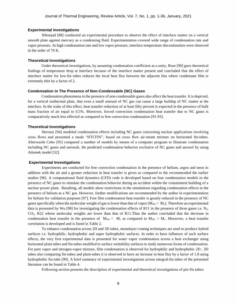
Jung [12] experimentally tested a plain tube, low-fin tubes and Turbo-C tubes designed for CFC11 and
CFC12 and concluded an eight times increase in HTC by using Turbo-C tubes as compared to the smooth tubes.
Similarly the analysis of alternative refrigerants over smooth, low-fin and Turbo-C tubes is also presented by Jung
[38]. It was found that for all refrigerants tested (R22, R407C and R410A) the HTCs for Turbo-C was the highest
about 2-8% as compared to that of plain tubes as well as the condensation behavior of R407C is somewhat different
than the other two refrigerants used and showed a 50% decrease in condensation HTC as compared to
R22.Subsequently in an experimental study carried out by Jung [39] for somewhat different refrigerant mixtures of
HFC32/HFC134a and HFC134a/HCFC123 (Non Azeotropic Refrigerant mixtures NARMs) for low-fin and Turbo-C
tubes. The study recommended that the HTCs across enhanced tubes are severely affected more showing a decrease
up to 96% than ideal values in respect of mixtures, and Turbo-C deteriorated more as compared to low-fin tubes. Also,
the enhancement ratio for mixtures was almost two times lesser than that of the ideal value.
An experimental investigation where petal shaped 3D fin-tubes (PF) and a smooth-tube are compared to test
the condensing behavior of R410; resulting in the enhancement factor for PF tubes are falling in the range of 7.5-8.3.
Furthermore for plain horizontal tube, the condensation HTC are found out to be smaller than that of Nusstle’s
prediction by 8.4% [40].In addition, Qin [2] obtained an experimental information against low and high thermal
conductivity 3D tubes by analyzing the condensation behavior of R134a on 3D tubes made up of copper and stainless
steel. For his investigation also the HTCs for plain tubes are smaller than that of Nusselt’s [31] prediction by 4.4 %
and 4.8% for copper and stainless respectively. Besides, the enhancement factor for copper tube is found out to be
higher than that of stainless steel because of its high thermal conductivity.
For the provision of an optimum design for condensers applications, Kang [41] evolved an experimental
correlation to measure the condensation effects with reference to falling film Reynolds number of HFC134a over two
different enhanced geometries videlicet low-fin and Turbo-C tubes. Turbo-C provided greater values of heat transfer
enhancement than low-fin tubes when compared with Nusselt’s correlation [31]. In addition to this, the condensation
HTC illustrates a decrease with the increase in falling film Reynolds number and wall sub cooling temperature.
Effect of varying the fin density, spacing and thickness is also a major area of concern while considering the
condensation effects [42]. Different scientists and researchers have reported this effect in their findings. In this aspect,
Yau [43] investigated in his experiment the influence of fin spacing on condensation of steam against a horizontal
integral-fin tube. He studies the condensation behavior for different fluid velocities of 0.5 m/s – 1.1 m/s and observed
that the reliance of augmentation on fin density did not rely on vapor velocity or condensation rate for the ranges used.
Thus, vapor side enhancement ratio was found out to be 3.6 for the fin spacing of 1.5 mm out of
1.0 mm – 20.5 mm.
Briggs [33], as described earlier, reported his experimental study for steam and R-113 at atmospheric
pressure, ethylene glycol at 2.5 KPa and also steam at 14 KPa against three fin- tubes of varying fin spacing. The best
performance was obtained with fin spacing of 1.5 mm, 1 mm and 0.5 mm for the different fluids used [44]. His findings

Journal of Thermal Engineering, Review Article, Vol. 7, No. 1, pp. 1-36, January, 2021
5
are also reported on the effect of circumferential fin spacing, longitudinal fin thickness and fin height where it is
concluded that the circumferential fin spacing is a governing factor affecting the condensation for three different types
of working fluids like water, ethylene glycol and R-113 [45, 46]. To explore the influence of fin density and fin
structure, experimental data is conducted by Badri [47] for standard-fin tubes (SFTs) and enhanced-fin tubes
(EFTs).EFTs are categorized for non-uniform fin structure with fin densities (fin per inch, fpi) of 39,48 and 56 fpi,
and show higher HTCs as compared to the SFTs. Among all the tubes tested the 39 fpi tube provided the highest
HTCs likewise the prediction of experimental data with the theoretical models is presented.
Furthermore Hameed [48] obtained his results for condensation heat transfer particularly for multi-stage flash
distillation process (MSF). In his experimental findings for steam condensers on HTC for three integral-fin tubes of
different materials specifically copper, aluminum, nickel and brass against different fin densities. He found out that
for each different type of material, tubes of fin density 11 fpi provided the highest heat transfer factor as compared to
15 fpi and 13 fpi. To find out the influence of fin density, low-fin tubes and 3D tubes comprising 26 fpi and 40 fpi
are tested against HCFC22. The finding of the study shows that 3D tubes provided higher overall HTCs along with
the higher condensing HTC for 40 fpi tube [49]. Similarly Yun [50] investigated in his experiment that stainless steel
integral-fin tube for R134a across different fin densities of 19 fpi and 26 fpi, as a result, the HTC for the mentioned
fin densities are 4.4 and 3.1 times greater than that of smooth tube.
Kumar [51] closely examined the effect of fin height. In his experimental work of five CIFTs of varying fin
heights of 0.45, 1.14, 1.47, 1.92 and 2.40 mm whereas fin density and thickness are kept constant. By using R143a as
a condensing fluid, it was found that the fin height of 0.45 mm provided the highest enhancement factor as compared
to the smooth tube model predicted by the Nusselt [31]. The impact of external surface and thermal conductivity on
film-wise condensation is experimentally tested for 2D and 3D fin horizontal tubes using R134a and R404A as
working fluids. Results indicate that condensation behavior of R404A is highly sensitive to thermal conductivity and
fin structure as compared to R134a.Additionally, to enhance condensation heat transfer of low thermal conductivity
surfaces 3D fin structure is more appropriate as compared to 2D fin structure. HTC verses heat flux across plain tubes
is compared with already present literature results and for present case [52], detail of tube material and fin geometry
can be seen in Table 4.
In order to overcome the corrosion problems involved in marine applications and power plants, the use of
titanium tubes along with copper-nickel alloys and stainless steel is the requirements for the refrigerant condensers
using sea water as a cooling medium. Where titanium offers more erosion resistance at the same time it provides
higher inside water velocities than the other materials. Moreover, the weight of the heat exchanger reduces as well for
the same heat transfer by using titanium tubes as its weight is lower by 55% and 50% than stainless steel and copper
alloys respectively. Therefore, to analyze the condensation behavior of R134a and ammonia using titanium tubes
initially experiments are conducted [53, 54 ]over plain and integral low-fin titanium tubes. Against R134a and a fin
density of 32 fpi, these enhanced fin tubes provide the enhancement factors ranging from 3 – 4 for different condensing
temperatures of 30˚C, 40˚C and 50˚C and there is a reduction in condensation HTC with increasing the wall sub
cooling. The theoretical model [41] suits best with a mean deviation of -5.5% for R134a whereas for ammonia as a
condensing fluid, the values of enhancement factor increases with an increase in the wall sub cooling. Also the
experimental data of ammonia is compared with theoretical models available and the Briggs and Rose model [33]
suits best.
Industry of refrigeration and air conditioning involves different generations of refrigerants beginning from
the naturals fluids like CO2 and ammonia, to the second generation of chloro-fluoro-carbons (CFCs) and hydro-chloro-
fluoro-carbons (HCFCs). The third involves the hydro-fluoro-carbons (HFCs) and the next is of low global warming
potential (GWP) refrigerants. The atmospheric problems affected by HFCs have been rising and this rise is still
accelerating therefore a replacement of refrigerants is needed. However, this transfer of refrigerant may involve
number of concerns. A part from safety, toxicity, thermal stability and ecological effect another main attention to be
paid is that the required refrigerant has equivalent thermo-dynamical and transport properties so that the equipment
executes the heat transfer functions well. The low GWP refrigerant of R1234zd(E) is deliberated to be a prospective
replacements for R134a, while isomers R1234ze(Z) and R1233zd(E) are expected to be low GWP alternatives for heat
pump applications [55-58]. Condensation heat transfer across enhanced and plain surfaces is analyzed using low GWP

Journal of Thermal Engineering, Review Article, Vol. 7, No. 1, pp. 1-36, January, 2021
6
refrigerants and comparisons are made. In this regard Chen [55] proposed an experimental work of 3D enhanced low-
fin surface with a plain one and concluded that enhanced surface provide 10.8 time more heat transfer as compared to
the plain surface. On the other hand, experiment conducted for smooth tube by Nagata [56] indicate that the
condensation HTCs of R1234ze(Z) is 10% more than that of R245fa whereas the condensation HTCs of R1233zd(E)
are comparable to that of R245fa. In order to fix this problem author suggested the need of more accurate transport
properties of R1233zd(E) for experiments. Incorporating different experimental observations of horizontal integral-
fin tubes, Marto [59] reviewed the problems involved in measuring the film condensation HTC on horizontal integral-
fin tubes. In his study he compared direct methods using wall temperature measurements and indirect methods i.e.
Wilson plot technique [60, 61]. Wilson plot technique seems and sounds more dependable while vapor side resistance
dominates being less expensive and more flexible comparatively. However, while using this method of Wilson plots
one needs to be highly careful while measuring HTC because of uncertainties [62, 63].
Various parameters effecting the performance of integral-fin tubes are discussed in the upcoming sections
along with the theoretical and experimental findings:
Condensate Retention-Surface Tension Effects
Theoretical Investigations
While investigating film condensation, surface tension effect is observed by many investigators in their
investigations specifically in the field of enhanced heat transfer where the horizontal fin-tube makes a contact with
highly wetting liquid [64]. The most important fact appeared as a result of the surface tension force, across low-fin
integral tubes, is ‘Gregorig’ effect [15, 65]. As a result, the liquid meniscus at the top of the fin surface is convex
while at its root it is concave; therefore the pressure at the fin top is higher than the fin root within the liquid phase as
compared to the pressure of the vapor [66]. This in turns leads to a high pressure gradient across condensate film
because of change in curvature of the tube surface [15]. Hence, Gregorig [66] described the condensate drainage from
the tips and flanks of the fins, thinning the condensate film on the fin surface and an increase in local heat transfer
rates. Many a researcher has included condensate retention in their studies and presented different theoretical and
experimental models to measure the retention angle [67]. Condensate retention is also known as liquid ‘flooding’, or
‘hold-up’ [68] and is characterized by the flooding angle ɸf, the angle measured from the top of the tube to the position
where the entire inter-fin space is filled with retained liquid [15]. The analytical models, to measure the flooding angle
on integral-fin and trapezoidal low-fin tubes was first developed by Honda et al [69, 70] as presented in equation 4
and 5 respectively:
ɸ𝑓 = 𝑐𝑜𝑠−1[(4ơ 𝑐𝑜𝑠 ß
𝜌𝑔𝑏𝑑𝑜) − 1] for s<2h (4)
ɸℎ = 𝑐𝑜𝑠−1 [1 − (4ơ 𝑐𝑜𝑠 ß
𝜌𝑔𝑏𝑑𝑜)],Cb=
ɸℎ𝜋⁄ (5)
Above equations show that the retention angle (flooding angle) is mainly a function of geometrical
parameters of tube and capillary constants and for fully flooded condition ‘ɸf ‘should be equal to zero. It varies directly
with vapor Reynolds number for the fluids having higher surface tension to density ratios and vice versa. Furthermore,
semi-empirical correlations accounting the relationship between retention angle and vapor velocity have also been
discussed in the literature [15, 45, 68, 71].
Survey of condensation heat transfer by Webb [72] depicted that surface tension forces are prominent in drainage the
fluid from fin tips to the inter-fin spacing. As a result, analytical model was developed and validated, on behalf of low
and high surface tension fluids, to calculate condensate retention angle for integral-fin tubes. An element by element
prediction model is presented [73] to evaluate condensate flow across integral-fin tube containing the effects of gravity
and surface tension by assuming the channel between the fins to be trapezoidal or rectangular. Fin and channels are

Journal of Thermal Engineering, Review Article, Vol. 7, No. 1, pp. 1-36, January, 2021
7
further divided into sub regions where local HTC is modeled comprising fin flank, fin tip and channels between the
fins. Considering different regions and sub-regions, height of condensate in fin channels, active and inactive fin heights
and mean condensation HTC are predicted, as presented in Table 2. The model can be extended to the enhanced fin
tubes further more analytical results are compared with the experimental work and provides an excellent agreement
[74]. As flooding is a function of fluid properties and geometrical parameters, to judge the surface tension effects on
a vertical surface, Shigeki [75] predicted a theoretical model to evaluate the consequence of capillary action on local
thinness of condensate film in the fin trough. Experimental findings of condensate retention are described in the
following sub-section:
Experimental Investigations
Condensate retention phenomenon is different for different types of fluids based on their surface tensions i.e.
for the high surface tension fluids, like water, both the effects (thinning of condensate film and condensate retention)
are nearly of same magnitude. Moreover, an increase in heat transfer is analogous to the increase in surface area
because of fins. Whereas for low surface tension fluids, such as refrigerants, the thinning of film condensation
increases heat transfer rate more than increase in surface area due to fins [30, 76].Besides, comparison of surface
tension of different working fluids can be observed in Table 1. STPG causes the incoming liquid to be retained at the
inter-fin spacing, on the bottom of tube, followed by a decrease in heat transfer rate at this section of the tube. Thus,
this condensate pattern on the surface is dependent on the wetting properties of the surface i.e. film-wise condensation
is produced on the surface having the good wet ability [77].In order to have an influence of fin spacing of condensation
tubes, condensate flow rate and surface tension to density ratio on retention angle, an experimental study is presented
involving eight horizontal integral-fin tubes with same fin root diameter as [45] but different fin spacing and zero
approaching vapor velocity. Results indicate that the retention angle increases with increasing the fin spacing and
decreasing the surface tension to density ratio of the condensate however it remains constant with the condensate
flow rate [78].
Sagia [79] carried out an assessment of surface tension effects of HFCs verses CFCs refrigerants so as to
reduce the environmental harm caused by the CFCs refrigerants. In his examination HFC-32, HFC-125, HFC-134a
and HFC-152a are investigated and their thermos-physical properties are presented by condensation of such fluids
across rectangular cross section integral-fin tubes. Vapor side HTC is calculated by varying different geometrical
parameters like: fin spacing, fin height, fin thickness and fin root tube diameter. The conclusion of his study reflected
that the enhancement ratio is strongly affected by the fin height and least by the tube diameter. His work mainly
focuses on the graphical comparisons of various thermos-physical parameters of different refrigerants. In another
experimental study by Masuda [80], where he examined the flooding phenomenon for trapezoidal-section integral-fin
tubes. His results show that the radiused fillet should be used to increase the ‘active’ area instead of sharp corners at
the fin root therefore, an increase in heat transfer enhancement can be accomplished. Yun [50] as well found a small
deviation between experimental and theoretical values in case of Honda and Nozu model [69] among all models when
he performed an experimental study regarding integral-fin tubes against R134a. In additional study where titanium
made integral-fin tube against R134a and ammonia were used as working fluids, it was found out that the condensate
flooded fraction decreased with the increase in saturation temperature [53, 54].
In undergoing the study to find out the influence of vapor velocity Satesh and Briggs [76, 81, 82] presented
the experimental data for forced-convection condensation horizontal integral-fin tubes. Condensate flooding was also
studied along with the effect of fin geometry. First five single integral-fin tubes were tested for varying fin spacing
and velocity between 2.3 and 10.2 m/s. later nine tubes were tested for a velocity range of 10-22.1 m/s. The flooding
was observed to be reduced as the velocity increases due to the vapor shear and was least for the highest velocity of
22.1 m/s. Similarly Claire [83] presented an experimental investigation to study the variation of condensate retention
verses vapor velocity for three different types of fluids such as water, R113 and ethylene glycol. The study ultimately
reached to a conclusion that when the retention angle is less than about π/2, it increases with increase in velocity
whereas it decreases with increase in velocity when it is greater than about π/2. Data of retention angle measured for
different fluids at zero air velocity is also presented in the investigation.

Journal of Thermal Engineering, Review Article, Vol. 7, No. 1, pp. 1-36, January, 2021
8
Shigeki [75] conducted an experimental procedure also, using water and R-113 over vertical tube and
concluded that the condensation HTC rises 3-3.5%, because of the combined effect of fin crest and trough, as compare
to that of Nusselt’s prediction [31]. To encounter the surface tension effects, first time the experimental data is
presented by Glushchuk [84] for condensation across cylindrical fin under various gravity conditions ranging from
normal gravity (go) to low gravity (0.05go).Force balance on the condensate flow is analyzed concerning STPG since
STPG has a significant influence in the regions where the condensate film thickness changes dramatically. Fin is
divided into seven different regions and heat transfer is observed at each region. Results show that the areas where
STPG overcomes gravity force, exhibit higher heat flux plus variation for different gravity conditions. For low gravity
circumstances the most intensive condensation appears on fin cylindrical surface and its tip moreover it provides the
unstable condensate flow along the cylindrical surface. Influence of heat flux, film thickness and fin surface
temperature are investigated verses fin surface arc length.
Reduction of Liquid Hold-Up:
Retained condensate on the heat transfer surface can adversely influence the heat transfer and energy
efficiency as it occupies the heat transfer area and restricts the flow [85]. Liquid hold-up can be significantly reduced
by placing the drainage strips at the tube bottom. Two types of drainage strips are mostly used-porous drainage strips
and solid drainage strips. Working principle of both strips is different, porous type strip pulls the condensate into its
pores as a result low pressure region is created at the bottom of the tube within the liquid; whereas by solid drainage,
a concave liquid meniscus is formed and pressure drop is created in the liquid region at the intersection of the strip
and fins that brings about the liquid drains off the strip along its sides [66, 68].
Yau [86] investigated horizontal integral-fin tubes for the condensation of steam with and without drainage
strips and concluded that the use of drainage strips reduces the flooding significantly. Similarly Trela [68] presented
analytical as well as an experimental model against a passive technique by using a drainage strip to measure
condensate drainage. By means of a solid strip for horizontal integral-fin tubes he obtained an increase of 6 – 25%, in
heat transfer. Active techniques are also used to reduce flooding; electro hydrodynamic (EHD) condensate drainage
is the most common among them [66, 87]. Butrymowicz [87] used experimental technique against EHD for tube
electrode arrangement using HCFC-123 as a working fluid and also proposed a theoretical model as below:
Φf=1
𝜋 𝑎𝑟𝑐 𝑐𝑜𝑠[𝜒(1 − 𝜒𝑑𝑒) − 1] [87] (6)
Where 𝜒𝑑𝑒=1
2
𝑁𝑒𝑔
𝐾𝑓 ,𝜒 = (𝐾𝐷 𝐾𝑓)−1
Although solid drainage strips are used in refrigeration and heat pump devices but porous drainage strips are
more effective by drawing the condensate into its pores. This was verified by Honda and Nozu [71] when they tested
flooding for a Polyvinyl chloride (PVC) solid strip and nickel porous drainage strips of same height. Resultantly,
solid strip gave the reduction of 8% whereas porous gave the reduction of about 48%.
Interface Resistance
Interface resistance is one of the primary factors that could be considered while analyzing the condensation
effects over smooth or enhanced surfaces. Nusselt [31] assumed in his theory of condensation against smooth
horizontal cylinder that the outer surface of condensate film is in thermal equilibrium with the vapor. However, he did
not consider the effect of interface matter. Although interface resistance is insignificant in most practical situations,
but cannot be neglected in case of condensation on enhanced surfaces where high rates of condensation and
condensation with metals are involved [13, 88]. Therefore, to incorporate the influence of interface matter,
condensation coefficient ‘f’ is defined as the fraction of vapor molecules striking the condensate surface which remain
in liquid state [13, 89]. It is obtained that the lower values of ‘f ‘ indicate large interface temperature difference [63,
90].
Journal of Thermal Engineering, Review Article, Vol. 7, No. 1, pp. 1-36, January, 2021
9
Experimental Investigations
Niknejad [88] conducted an experimental procedure to observe the effect of interface matter on a vertical
smooth plate against mercury as a condensing fluid. Experimentation covered wide range of condensation rate and
vapor pressure. At high condensation rate and low vapor pressure, interface temperature discontinuities were observed
in the order of 70 K.
Theoretical Investigations
Under theoretical investigations, by assuming condensation coefficient as a unity, Rose [90] gave theoretical
findings of temperature drop at interface because of the interface matter present and concluded that the effect of
interface matter for low-fin tubes reduces the local heat flux between the adjacent fins where condensate film is
extremely thin by a factor of 2.
Condensation in The Presence of Non-Condensable (NC) Gases
Condensation phenomena in the presence of non-condensable gases also affect the heat transfer. It is depicted,
for a vertical isothermal plate, that even a small amount of NC gas can cause a large buildup of NC matter at the
interface. In the wake of this effect, heat transfer reduction of at least fifty percent is expected in the presence of bulk
mass fraction of air equal to 0.5%. Moreover, forced convection condensation heat transfer due to NC gases is
comparatively much less effected as compared to free convection condensation [91-93].
Theoretical Investigations
Herranz [94] modeled condensation effects including NC gases concerning nuclear applications involving
cross flows and presented a mode “HTCFIN”, based on cross flow air-steam mixture on horizontal fin-tubes.
Afterwards Cobo [95] compared a number of models by means of a computer program to illustrate condensation
including NC gases and aerosols. He predicted condensation behavior exclusive of NC gases and aerosol by using
Adamek model [32].
Experimental Investigations
Experiments are conducted for free convection condensation in the presence of helium, argon and neon in
addition with the air and a greater reduction in heat transfer is given as compared to the recommended the earlier
studies [96]. A computational fluid dynamics (CFD) code is developed based on four condensation models in the
presence of NC gases to simulate the condensation behavior during an accident within the containment building of a
nuclear power plant. Resulting, all models show restrictions in the simulations regarding condensation effects in the
presence of helium as a NC gas. However, further modifications are recommended by the author in experimentation
for helium for validation purposes [97]. Free film condensation heat transfer is greatly reduced in the presence of NC
gases specifically when the molecular weight of gas is lower than that of vapor (MNG < Mv). Therefore an experimental
data is presented by Wu [98] for investigating the condensation effects of R11 in the presence of three gases i.e. N2,
CO2, R22 whose molecular weights are lower than that of R11.Thus the author concluded that the decrease in
condensation heat transfer in the presence of MNG < Mv as compared to MNG > Mv. Moreover, a heat transfer
correlation is developed and is listed in Table 2.
To enhance condensation across 2D and 3D tubes, monolayer coating techniques are used to produce hybrid
surfaces i.e. hydrophilic, hydrophobic and super hydrophobic surfaces. In order to have influence of such surface
effects, the very first experimental data is presented for water vapor condensation across a heat exchanger using
horizontal plain tubes and fin-tubes modified to surface wettability surfaces to study numerous forms of condensation.
For pure vapor and nitrogen-vapor mixture, film condensation is observed for hydrophilic and hydrophobic 2D , 3D
tubes also comparing fin-tubes and plain-tubes it is observed to have an increase in heat flux by a factor of 1.8 using
hydrophobic fin-tube [99]. A brief summary of experimental investigations across integral-fin tubes of the presented
literature can be found in Table 4.
Following section presents the description of experimental and theoretical investigations of pin-fin tubes:

Journal of Thermal Engineering, Review Article, Vol. 7, No. 1, pp. 1-36, January, 2021
10
PIN-FIN TUBES
The condensation heat transfer effect on different geometries of integral-fin tubes has previously been
explained in detail. In the recent years, different manufacturing techniques are used to enhance the heat transfer effects
by maximizing the surface area resulting change in the fin profiles. A 3D rectangular cross section “pin -fin” geometry
can be constructed since the criterion to judge the condensation heat transfer effects only an integral-fin tube is not
enough [19, 27, 100-103]. Tubes comprising such tubes are called “pin-fin tubes” and are clarified by six dimensions
in particular such as: pin-root diameter, longitudinal pin spacing and thickness, circumferential pin spacing and
thickness, and pin height [100].
A brief description of condensation heat transfer variation in terms of the above mentioned dimensions and
other parameters is described in the following sub-sections.
Experimental heat transfer measurements
Geometrical Effects are presented in the literature regarding different types of fluids to test condensation behavior by
applying pin-fin tubes considering different geometrical parameters i.e. fin height, spacing and thickness. In view of
this, Briggs [27] determined experimentally the vapor side HTC for a number of six 3D pin-fin tubes against R-113
and steam. The study concluded that for both fluids, a major increase in overall HTC is seen by making a comparison
with a plain tube. Vapor side HTC enhancement values are found out to be between 3.6 – 9.9 and 2.6 – 2.9 for steam.
Similarly, for ethylene glycol the best performing tube provided the enhancement ratio of 5.5 which is about 24%
higher than the same 2D integral-fin tubes when tests are performed for eleven pin-fin tubes and a smooth tube.
As far as the geometry of tube is concerned, as the pin height increases the heat transfer enhancement
increases and followed by a decrease with the increase in circumferential pin spacing. Also by varying only the
circumferential fin spacing and thickness the enhancement ratio reached up to 4 for steam by using five 3D pin-fin
tubes besides all tested pin-fin tubes provided extensively higher heat transfer enhancement for the same integral-fin
tube. The same for R-113 again as the pin spacing decreases; there is an increase in vapor-side heat transfer
enhancement. And the best performing tube provided an increase of almost 14% to that of equivalent integral-fin tube
[104].Whereas for ethylene glycol, the best performing pin-fin tube gave the enhancement factor of 4.9 and is almost
20% higher than the equivalent 2D integral-fin tubes. As far as fin spacing is concerned, the heat transfer enhancement
increases with the decrease in fin spacing and an optimum value of fin spacing is determined while incorporating fin
spacing variation cases [100-102].
Optimum Conditions for fins are defined by two techniques: the first one is related to the fin profile so that the
minimum volume of fins should be used for the given heat transfer; second is to find out the minimum volume of fins
in terms of fin dimensions used for the given heat dissipation rate and fin shape. The second approach is much
appropriate for design problems whereas the first involves more expenses in manufacturing [17, 19, 105].So an
experimental data related to ethylene for six pin-fin tubes shows that vapor side enhancement ratios of 3-5.5 and best
performing tube presented 17% more than enhancement factor than that of equivalent optimized integral-fin tube
[106]. An additional experimental work is presented for three different kinds of tubes: copper, brass and bronze instead
of copper only for the condensing fluids of R113 and ethylene glycol by varying the pin height. As a result,
enhancement ratio increases with the increase in pin height for the both fluid tested and copper tubes offered the
maximum heat transfer enhancement ratios. On the other hand, vapor side heat transfer enhancement factor is not a
strong function of thermal conductivity in case of R-113, however, is a strong function in case of ethylene glycol [23].
Theoretical Heat Transfer Measurements
A semi-empirical correlation is developed by Ali [107] for pin-fin tubes considering the effects of surface
tension and gravity under free convection conditions. This correlation is basically obtained for three fluids i.e.: R113,
steam and ethylene glycol condensing on eleven tubes of varying geometries and provided a good agreement with the
experimental values predicting the dependence of vapor side HTC for different tube geometries and fluid types. While
analyzing forced convection conditions, Kundu [108] presented an analytical model called “Adomian decomposition
method (ADM)”for optimum design of pin-fins under laminar steam flow for a horizontal tube. He ultimately

Journal of Thermal Engineering, Review Article, Vol. 7, No. 1, pp. 1-36, January, 2021
11
concluded that there is a strong influence of variation in geometrical parameters of fins and thermo-physical
parameters on temperature distribution and fin performance. This temperature distribution is measured across the
length of the tube to judge the thermal conductivity of fin material. He also presented a numerical technique followed
by a finite difference method (FDM) to validate his identical analytical results and found out that fin efficiency and
maximum heat transfer rate decreases with increasing the fin-base temperature though the optimized fin diameter is
an increasing function with fin-base temperature, Optimization is carried out by either of the two techniques mentioned
above, in addition the heat transfer rate is an increasing function of vapor partial pressure but optimum fin diameter
decreases with an increase in vapor partial pressure [105].
Condensate retention-surface tension effects
Experimental as well as analytical findings obtained by the above mentioned researchers for pin-fin tubes
has revealed that the enhancement ratio is strongly a function of active surfaces of the tubes including surface areas
of pin and tubes not covered by the condensate due to surface tension effects.
Condensate drainage induced by surface tension is strongly affected by the fin shape [4]; so taking into
consideration condensate retention angle is measured for 15 rectangular pin-fin tubes under static conditions and
correlation is developed via three different fluids specifically water, R113 and ethylene glycol. Results showed that
the angle measurements are larger than those of the same integral-fin tubes [109]. The resulting expression is as
follows:
ɸ𝑓 = 𝐶𝑜𝑠−1 [(1 − 𝐶 ×𝑠𝑐
𝑡𝑐 ) (
2ơ
𝜌𝑔𝑠𝑅𝑜) -1] for s<2h (7)
In addition to the semi empirical model [93], an analytical model is predicted by Ali [110]for the condensate
flooding across horizontal pin-fin tubes by taking into account the forces acting in upward and downward direction
upon the retained condensate. Model also shows a good agreement with the experimental results.
Considering condensate retention for forced convection intended for pin-fin tubes, a new experimental data
is presented by Abubaker [111] for water, ethylene glycol and R-141b. For the variation in circumferential pin spacing
only and for the entire set of tubes tested the retention angle measures reveals that by increase in vapor velocity the
retention angle increases. He also concluded that the circumferential pin spacing was found to be an important factor
affecting the condensate retention angle despite the effect of vapor velocity.
As overall pin-fin tubes provided the better results as those of integral-fin tubes in terms of HTCs and
enhancement ratios for the same geometry although more work is needed to encounter the effects of pin-fins across
different geometries of pin-fins. A summary of theoretical and experimental findings across pin-fin tubes is listed in
Table 2, 3 and 4 respectively.
Table 1. Surface tension ratio of surface tension to density ratio of various working fluids [54]
Fluid σ [mNm-1]
30oC 40oC 50oC
σ/ρ .10-6 [m3 s-2]
30oC 40oC 50oC
Water 71.19 69.60 67.94 71.51 70.15 68.77
Ammonia 23.82 20.29 17.43 39.11 35.02 30.96
R134a 7.42 6.13 4.89 6.25 5.34 4.44
R22 7.4 6.04 4.74 6.31 5.35 4.38
R507A 3.80 2.68 1.63 3.72 2.78 1.82
R407C 6.23 4.87 3.59 5.59 4.57 3.54

Journal of Thermal Engineering, Review Article, Vol. 7, No. 1, pp. 1-36, January, 2021
12
Table 2. Summary of theoretical findings of Integral-Fin tubes
Author Model/Correlation
Adamek [32] ��𝑡𝑢𝑏 = 4𝑁𝐿(��𝑡𝑢𝑏𝑒,𝑢 + ��𝑓𝑙 )
��𝑡𝑢𝑏𝑒,𝑢 = 4𝑁𝐿��𝑢
��𝑓𝑙 = do/2(∅𝑓-0.1𝜋)( ��12 + ��01)
Briggs [33] 𝜀𝛥𝑇 =
𝑄𝑓𝑙𝑜𝑜𝑑 + 𝑄𝑓𝑖𝑛 + 𝑄𝑖𝑛𝑡𝑒𝑟𝑓𝑖𝑛
𝑄𝑝𝑙𝑎𝑖𝑛
𝑄𝑝𝑙𝑎𝑖𝑛 = 𝜋𝑑(𝑠 + 𝑡)𝑞𝑝𝑙𝑎𝑖𝑛
𝑄𝑓𝑖𝑛 = ∅𝑓 {𝑑𝑜𝑡𝑞𝑡𝑖𝑝 + (1 − 𝑓𝑓) (𝑑0
2−𝑑2
2) 𝑞𝑓𝑙𝑎𝑛𝑘}
𝑄𝑓𝑙𝑜𝑜𝑑 = (𝜋 − ∅𝑓)𝑑𝑜𝑡𝑞𝑡𝑖𝑝,𝑓𝑙𝑜𝑜𝑑
𝑄𝑖𝑛𝑡 = ∅𝑓(1 − 𝑓𝑠)𝑑𝑠𝑞𝑖𝑛𝑡
𝑓𝑠 = (2𝜎
𝜌𝑔𝑑ℎ) (𝑡𝑎𝑛 (
∅𝑓
2) ∅𝑓)
𝑓𝑓 = (4𝜎
𝜌𝑔𝑑ℎ) (𝑡𝑎𝑛 (
∅𝑓
2) ∅𝑓)
Kang [41] 𝑁𝑢𝑐 = 0.148𝑅𝑒𝑓−0.201 𝑃𝑟1.461𝑤0.063𝑒0.179
(w,e are non-dimensional parameters. E=h/p, w=gdo3/υ)
Trela [68]
Yau [86]
∅𝑓 = 1𝜋𝑎𝑟𝑐𝑐𝑜𝑠(𝜖(1 − 𝜖𝑑) − 1)
(𝜖 𝑖𝑠 𝑑𝑖𝑚𝑒𝑛𝑠𝑖𝑜𝑛𝑙𝑒𝑠𝑠 𝑝𝑎𝑟𝑎𝑚𝑒𝑡𝑒𝑟 = 𝐾𝐷𝐾𝐶 ,
𝜖𝑑𝑖𝑠 𝑑𝑟𝑎𝑖𝑛𝑎𝑔𝑒 𝑝𝑎𝑟𝑎𝑚𝑒𝑡𝑒𝑟 = 𝐾𝑚 + ∆𝑥ℎ𝐾𝐶)
∅𝑓 = 1𝜋𝑎𝑟𝑐𝑐𝑜𝑠(0.415𝜖 − 1)
Baiser [101] 𝑁𝑢𝑐 = 0.036𝑅𝑒𝑐0.8 𝑃𝑟𝑐
0.33( 𝜇𝑐
𝜇𝑤 )
Badri [73]
𝛼𝑓𝑙𝑘,ᴪ𝑣 = 0.942(ℎ𝑓𝑔𝑘3
ℎ𝑎,ᴪ𝑣𝜐∆𝑇𝑓𝑙𝑘,ᴪ𝑣)
1
4(∆𝜌𝑔𝑦,𝑜 +𝜎𝑐𝑜𝑠ᴪ
𝑟𝑏𝑎𝑠,ᴪ𝑣ℎ𝑎,ᴪ𝑣)1/4
𝛼𝑐ℎ𝑎,𝑠ᴪ𝑣 = (𝜎ℎ𝑓𝑔𝑘3
4𝑙𝑐ℎ𝑎,𝑠,ᴪ𝑣2 𝑟𝑏𝑎𝑠,ᴪ𝑣𝜐∆𝑇𝑐ℎ𝑎,ᴪ𝑣
)1
4
𝛼𝑡𝑖𝑝,ᴪ𝑣 = 2𝑟𝑡𝑖𝑝
𝑡𝑡𝑖𝑝(𝛼𝑡𝑖𝑝,𝑠,ᴪ𝑣 − 𝛼𝑡𝑖𝑝,𝑔,ᴪ𝑣) + 𝛼𝑡𝑖𝑝,𝑔,ᴪ𝑣
𝛼𝑡𝑖𝑝,𝑠,ᴪ𝑣 = (𝜎ℎ𝑓𝑔𝑘3
4𝑟𝑡𝑖𝑝,ᴪ𝑣3 𝜐∆𝑇𝑡𝑖𝑝,ᴪ𝑣
)1/4
𝛼𝑐ℎ𝑎,𝑔,ᴪ𝑣 = 𝜏3(2ℎ𝑓𝑔 𝑘
3∆𝜌𝑔
𝑅𝑏𝑎𝑠𝜐∆𝑇𝑐ℎ𝑎,ᴪ𝑣)1/4
ℎ𝑖,ᴪ𝑣 = 𝑟𝑏𝑎𝑠,ᴪ𝑣 + ℎ𝑐ℎ𝑎,ᴪ𝑣
Wu [98]
Wu [112]
𝑞 𝑞𝑁𝑢⁄ = 𝑎𝑊𝑁𝐺
𝑏
(a,b are constants for each non-condensable gas
q= heat flux with non- condensable gas and qNu is haet flux based on Nusselt’s solution)
𝑇𝑡𝑝 − 𝑇𝑤 =1.099𝑞1.26𝑑𝑣0.39
𝑘𝐶𝑅𝑒0.5(𝑔2𝑑𝜌𝐶𝜇𝐶ℎ𝑓𝑔2)0.13

Journal of Thermal Engineering, Review Article, Vol. 7, No. 1, pp. 1-36, January, 2021
13
Table 3. Summary of theoretical findings of Pin-Fin tubes
Author Model/Correlation
Ali [45] ɸ𝑓 = 𝐶𝑜𝑠−1 [1
𝑅𝑜{𝐴 × 𝑠 × (
𝜎
𝑣2 𝑠𝜌𝑐)𝑎 × (
𝑠𝑔
𝑣2)𝑏 × (𝜌𝑎
𝜌)𝑐} -1 ]
(A,a,b,c are constants, v=0-19m/s)
Ali [107] 𝜀𝛥𝑇 =
𝑄𝑡𝑖𝑝 + 𝑄𝑓𝑙𝑎𝑛𝑘1 + 𝑄𝑓𝑙𝑎𝑛𝑘2 + 𝑄𝑟𝑜𝑜𝑡1 + 𝑄𝑟𝑜𝑜𝑡2
𝜋𝑑𝑜(𝑡 + 𝑠){0.728(𝜌��𝑔𝛥𝑇3𝑘3ℎ𝑓𝑔
𝑑𝜇)
( �� =ρ-ρv)
Ali [109]
Ali [110]
ɸ𝑓 = 𝐶𝑜𝑠−1 [(1 − 𝐶 ×𝑠𝑐
𝑡𝑐 ) (
2ơ
𝜌𝑔𝑠𝑅𝑜) -1] (s<2h)
𝜃𝑓 = 𝑐𝑜𝑠−1 (1 −𝐻𝑎𝑣𝑔
𝑅𝑜)
𝐻𝑎𝑣𝑔={𝜎(𝑠+𝑡+2ℎ)×
(𝑠𝑡𝑐+𝑡𝑡𝑐+2ℎ𝑡𝑐)
(𝑠𝑡𝑐+𝑡𝑡𝑐+2ℎ𝑡𝑐)+(𝑠+𝑡)𝑠𝑐}+{𝜎(𝑠+𝑡)×
(𝑠+𝑡)𝑠𝑐(𝑠𝑡𝑐+𝑡𝑡𝑐+2ℎ𝑡𝑐)+(𝑠+𝑡)𝑠𝑐
}−𝜎(𝑠+𝑡)
𝜎𝑔(𝑠𝑡𝑐ℎ+(𝑠+𝑡)𝑠𝑐ℎ
𝑡𝑐𝑠𝑐)
(v=0-19m/s)
Ali [111] ɸ𝑓 = 𝐶𝑜𝑠−1 [(1 − (0.4919 − 1.306 (ơ
𝜌𝑅2 𝑔)) ×
𝑠𝑐
𝑡𝑐 ) (
2ơ
𝜌𝑔𝑠𝑅𝑜) -1] ( s<2h)
Kundu [105,108] 𝑄𝑖 = 2.287𝑑𝑓𝐿𝑓(𝑇𝑠𝑎𝑡 − 𝑇𝑏)[
𝑔𝜌𝑙(𝜌𝑙−𝜌𝑣)𝑘𝑙3ℎ𝑓𝑔
′
𝜇𝑙(𝑇𝑠𝑎𝑡−𝑇𝑏)(𝑑𝑓)]1/4
𝑄𝑜 = 0.5718𝑑𝑓2(𝑇𝑠𝑎𝑡 − 𝑇𝑏)[
𝑔𝜌𝑙(𝜌𝑙−𝜌𝑣)𝑘𝑙3ℎ𝑓𝑔
′
𝜇𝑙(𝑇𝑠𝑎𝑡−𝑇𝑏)(𝑑𝑓)]1/4
𝑄𝑖 = 𝜇𝑑𝑓𝐿𝑓(𝑇𝑠𝑎𝑡 − 𝑇𝑏)[ℎ𝑖,𝑓𝑖𝑛]ξ=1
𝑄𝑜 =𝜋𝑑𝑓
2(𝑇𝑠𝑎𝑡−𝑇𝑏)
4[ℎ𝑖,𝑓𝑖𝑛] ξ=1
Journal of Thermal Engineering, Review Article, Vol. 7, No. 1, pp. 1-36, January, 2021
14
Table 4. Summary of experimental literature review
Author Fin type Refrigerants Tube
Material
Inner tube
Diameter
di
(mm)
Fin
Pitch
p
(mm)
Fin
Height
h
(mm)
Fin
Spacing
s
(mm)
Fin
Density
fpi
Fin thickness
at fin tip
ttip
(mm)
Temperature
(˚C )
Heat Flux
q
(KW/m2)
Qin [2] Plain
3D
R134a Copper
&Stainless
Steel
Copper
Stainless
steel
9
9
9
--
1.50
0.74
--
1.40
0.84
--
1.20
0.77
--
--
--
--
--
--
TSat = 39
Sub cooling = 3.2 – 10.5
--
Jung [12] Plain,
Low- fin
Turbo- C
CFC11
CFC12
HCFC123
HFC134a
Copper
--
15.9
-- --
1.214
0.760
--
0.40
--
26
42
--
0.252
0.250
TVapor
= 39
Sub cooling = 3 – 8
Plain tube = 6 – 15
Low-fin = 35 – 76
Turbo-C =47 –97
Masuda [22]
Plain
Low- fin
Nt = 14
Ethylene-
Glycol
R113
Steam
Copper
9.78
--
--
--
1.59
--
0.25
0.5
1
1.5
2,4,6,8,
10,12,16,1
8, 20
--
--
--
--
--
--
--
--

Journal of Thermal Engineering, Review Article, Vol. 7, No. 1, pp. 1-36, January, 2021
15
Table 5. Summary of experimental literature review (cont.)
Author Fin type Refrigerants Tube
Material
Inner tube
Diameter
di
(mm)
Fin
Pitch
p
(mm)
Fin
Height
h
(mm)
Fin
Spacing
s
(mm)
Fin
Density
fpi
Fin
thickness at
fin tip
ttip
(mm)
Temperature
(˚C )
Heat Flux
q
(KW/m2)
Ali [23] Plain
3D Pin-fin
2D Integral-
fin
Ethylene –glycol
R113
Copper
Bronze
Brass
--
9.6
9.6
--
--
0.9, 1.6
0.9, 1.6
--
1.07
1.03
1.03
1
--
--
--
--
0.5
0.5
-- --
Briggs [27]
Plain
3D Pin-fin
Nt = 7
R113
Steam
Copper 9.6
9.6
-- --
0.9, 1.6
--
0.5, 1.1
--
0.5
-- --
Belghazi [29]
Plain
Integral-fin
Trapezoidal-
fin
Gewa C*
Nt = 5
HFC134a
HFC23/HFC134a
Copper 14.2
14
14.4
14
--
0.82
0.97
1.34
2.31
0.635
--
--
1.3
1.45
1.5
1.3
--
--
--
--
--
--
0.2
0.25
0.33
0.38
0.16
--
-- --
Ji [34]
Plain
Integral-fin
Pyramid
Reentrant
cavity
surface
R134a Copper 16.41
16.28
14.53
15.07
--
--
1.40
0.86
0.63
--
--
--
--
--
32
35
40
--
--
--
--
Tsat = 40
8 – 86
Kumar [35]
Plain
CIFT
SIFT
Steam Copper 18.42
18.42
18.42
--
--
--
--
1.10
1.06
--
1.46
1.45
--
--
--
1.11
1.11
-- --

Journal of Thermal Engineering, Review Article, Vol. 7, No. 1, pp. 1-36, January, 2021
16
Table 6. Summary of experimental literature review (cont.)
Author Fin type Refrigerants Tube
Material
Inner tube
Diameter
di
(mm)
Fin
Pitch
p
(mm)
Fin
Height
h
(mm)
Fin
Spacing
s
(mm)
Fin
Density
fpi
Fin thickness
at fin tip
ttip
(mm)
Temperature
(˚C )
Heat Flux
q
(KW/m2)
Kumar [36]
Plain
CIFT
SIFT
PCIFT
Nt = 11
Steam
R134a Copper --
--
--
--
--
0.63
2.57
0.64
2.56
0.63,
2.58
--
1.1,
0.8
1.06
0.78
0.76
0.96
-- -- 10,40
--
0.10, 1.11
0.11, 1.11
0.10, 1.15
Tsat = 39 Steam: 200 – 600
R134a: 40 –80
Kumar [37] Plain
CIFT
SIFT
Nt = 10
Water
R134a Copper 18.42
18.42
18.42
--
0.53
0.63
0.80
1.07
2.57
0.64
2.56
--
0.6,0.7
0.78
0.8
1.10
0.78
1.11
--
--
--
10,23,3
1,
40,47
10,40
0.08,0.10
0.11,0.12,
1.11
0.11,1.11
Tsat = 39
Water: 150 – 650
R134a: 25 – 80
Jung [38]
Plain
Low-fin
Turbo-C
R22
R407C
R410A
-- -- -- -- -- --
26 -- Tsat = 39
Sub cooling = 3 – 8
--
Jung [39] Low-fin
Turbo-C
HFC32/
HFC134a
HFC134a/
HCFC123
-- -- -- -- -- 26 -- Tsat = 39
Sub cooling = 3 – 8
Turbo-C: 6 –15
Kang [41] Low-fin
Turbo-C
Nt = 4
HFC134a -- -- 0.98
0.61
1.42
0.79
1.03
1.13
-- -- -- Tsat =59.8 --

Journal of Thermal Engineering, Review Article, Vol. 7, No. 1, pp. 1-36, January, 2021
17
Table 7. Summary of experimental literature review (cont.)
Author Fin type Refrigerants Tube
Material
Inner tube
Diameter
di
(mm)
Fin
Pitch
p
(mm)
Fin
Height
h
(mm)
Fin
Spacing
s
(mm)
Fin
Density
fpi
Fin thickness
at fin tip
ttip
(mm)
Temperature
(˚C )
Heat Flux
q
(KW/m2)
Ali [42] Plain
Pin-fin
Nt = 19
R113
Ethylene- Glycol
Water
Copper
Brass
Bronze
9.65 -- --
0.9
1.22
1.6
--
0.405
0.5
1.1, 1.5
-- --
0.305, 0.5
-- R113:
31.2 – 176.9
Ethylene Glycol:
290.1 – 1351.9
Ali [45] Integral-fin
Nt = 8
Water
Ethylene- Glycol
R141b
Copper 8 -- 0.8
0.8
0.8
0.8
0.8
1.6
1.6
1.6
0.5
0.75
1
1.25
1.50
0.60
1
1.50
-- 0.5
0.5
0.5
0.5
0.5
0.3
0.5
0.5
-- --
Briggs [46]
Integral-fin
Pin-fin
Nt = 15
Water
Ethylene- Glycol
R113
--
--
--
--
--
--
0.9
1.6
0.5,1,
1.5
0.5,1,
1.1,1.5
Sc:
0.5,1,
1.5
--
--
0.5 -- --
Badri [47] SFT
EFT
Nt = 10
R134a Copper 15.5
16
15.7
15.5
15.4
15.5
16
15.7
15.5
15.4
-- 0.96
0.97
0.81
0.95
0.72
0.98
0.97
0.81
0.95
0.72
-- 39
39
48
48
56
39
39
48
48
56
0.20
0.17
0.17
0.17
0.16
0.20
0.17
0.17
0.17
0.16
Tsat = 37 --

Journal of Thermal Engineering, Review Article, Vol. 7, No. 1, pp. 1-36, January, 2021
18
Table 8. Summary of experimental literature review (cont.)
Author Fin type Refrigerants Tube
Material
Inner tube
Diameter
di
(mm)
Fin
Pitch
p
(mm)
Fin
Height
h
(mm)
Fin
Spacing
s
(mm)
Fin
Density
fpi
Fin thickness
at fin tip
ttip
(mm)
Temperature
(˚C )
Heat Flux
q
(KW/m2)
Hameed [48]
Integral-fin
Nt = 3
Steam
V=1 – 3m/s
Copper
Nickel
Aluminum
Bromine
32 -- 2.1 -- 11,13,15 -- -- --
Cheng [49] Low-fin
3D
Nt = 3
HCFC22 -- 13.74,14.61
14.67,14.68
14.90,15
-- -- 26,40 0.17, 0.23 -- --
Yun [50] Plain
Integral-fin
R134a Copper,
Stainless
steel
12.68, 13.74
10.79
-- 1.19 -- --
19,26
-- Tsat = 20,30 --
Kumar [51] Plain
CIFT
Nt = 6
R134a -- 11.95 --
--
--
0.45
1.14
1.47
1.92
2.40
--
--
--
12
--
0.7
-- --
Zhao [52] 2D
3D
R134a
R404A
Iron-
cupronickel
Aluminum-
brass
Iron-
cupronickel
Aluminum-
brass
16.59
16.58
16.48
15.16
--
--
--
--
1.29
1.27
1.26
1.24
--
--
--
--
0.30
0.29
Tsat = 30 --
Fernandez
[53]
Plain
CIFT
R134a Titanium 15.85 --
0.8
--
0.965
--
0.5
--
32
--
--
Tsat = 30,40,50
Sub cooling = 0.5 – 9
--

Journal of Thermal Engineering, Review Article, Vol. 7, No. 1, pp. 1-36, January, 2021
19
Table 9. Summary of experimental literature review (cont.)
Author Fin type Refrigerants Tube
Material
Inner tube
Diameter
di
(mm)
Fin
Pitch
p
(mm)
Fin
Height
h
(mm)
Fin
Spacing
s
(mm)
Fin
Density
fpi
Fin thickness
at fin tip
ttip
(mm)
Temperature
(˚C )
Heat Flux
q
(KW/m2)
Fernandez
[54]
Plain
CIFT
Ammonia Titanium 15.85 --
0.8
--
0.965
--
0.5
--
32
--
--
Tsat = 30,35,40,45
Sub cooling = 1– 8
Chen [55] Plain
3D
Nt = 2
R1233zd(e)
(HFO)
Copper 21.85 -- --
0.95
-- -- -- Tsa t= 36.1
Butrymowicz
[66, 87]
Plain
Integral-fin
R123
Copper
Nickeline
Brass
13,11.02,13.80
13
--
0.97
1.35
0.54
--
1.38
1.50
0.40
-- --
26
19
47
--
0.21
0.29
0.27
Tsat = 40
Trela [68] Plain
Integral-fin
CFD-11 Brass 10
19
--
1
--
0.5
--
--
25
--
--
-- --
Ali [78]
Integral-fin
Nt = 8
Water, Ethylene
glycol, R-141b
Copper -- -- 0.8
0.8
0.8
0.8
0.8
1.6
1.6
1.6
0.5
0.75
1
1.25
1.50
0.60
1
1.50
26
21
17
15
13
29
17
13
0.5
0.5
0.5
0.5
0.5
0.3
0.5
0.5
-- --
Glushchuk
[84]
Cylindrical HFE7100 Brass -- -- 8.9 -- -- -- Tsat = 45 – 55 --
Hu [99] Plain
2D, 3D
Water Copper 12.09
12.62
-- --
0.87
-- --
26
-- -- --
Ali [100] Plain
Integral-fin
Pin-fin
Nt = 11
Ethylene glycol Copper 9.6 -- --
0.9,1.6
0.5,1,1.5
0.5,1,1.1,1.5
Sc:0.5,1,1.5
-- --
0.5
--
--
Baiser [101]
Plain
Pin-fin
Nt = 5
Steam Copper 9.6 -- --
1.6
0.5,1,1.5
-- 0.5
tc = 0.5,1
-- --
Ali [104,109] Integral-fin
Pin-fin
Nt = 5
Water, R113,
Ethylene glycol
Copper,
Brass,
Bronze
9.6 -- 0.9,1.6
0.5,1,1.5
-- 0.5, tc = 0.5,1
tc = 0.45,0.5,
0.55,0.75,0.80,1
-- --

Journal of Thermal Engineering, Review Article, Vol. 7, No. 1, pp. 1-36, January, 2021
20
CONDENSATION ACROSS TUBE BUNDLE
To judge the condensation effects, different types of condensing technologies are used and shell and tube type
heat exchanger is one of those technologies. Condensation across bundle of tubes is primarily different from
condensation on single tube because of inundation effects [28, 113, 114]. The inundation effect is defined as an effect
of condensate flowing from the higher tubes in a bank on the performance of a specified row. Consequently, thickness
of condensate film increases around lower tubes and HTC decreases [115]. Theoretical as well as experimental
investigations concerning the tube bundle are discussed in the following sub-sections:
Theoretical findings
Studies have been carried out on condensation outside the tube banks of plain tubes and fin- tubes instead of
single tube of heat exchangers. A part from theoretical models, experimental models exist in the literature for
estimating condensing heat transfer rates across the tube bundle accounting the effects such as: vapor shear, surface
geometry, condensate retention, coolant velocity and gravity. Based on the Nusselt’s first model for the horizontal
tube bundle [64, 116]:
𝑎𝑛
𝑎1= 𝑛−𝑚 (8)
different researchers found out the value of row-effect exponent ‘m’ for a plain tube bundle depending on experiments,
as a result Nusselt’s value (m=1/4) remained unsuitable. Moreover, for a vertical row of enhanced and wire wrapped
tubes, very little value of row effect is observed showing that surface geometry strongly affects the heat transfer
behavior [64, 116-120].
Condensation inundation in terms of local HTC against vertical array of horizontal tubes has commonly been
a point of researchers where they found out, that the local value is obtained by dividing the heat exchanger into small
zones, at the midpoint of each copper tube: a smooth tube, a low-fin enhanced and two tubes with 3D enhanced
geometry for R-134a. Comparatively, for high liquid film Reynolds number low-fin tube provided a higher HTC
against the minimal vapor shear. In addition, a new relation of tube-row effect for low-fin tube is recommended for
design purposes [120]. While comparing the different models available in the literature for 2D tubes [121], it is
concluded that the these models are not able to predict precisely the behavior of condensation across 3D tubes.
Whereas 2D tubes show less sensitivity to the inundation level and provided the improved prediction with the
theoretical correlation. Table 5 summarizes the theoretical models for the tube bundle whereas a summary of
experimental work is listed in Table 6.
Experimental findings
Experiments were conducted by Cheng [119]to study the condensation characteristics on a vertical array of
six different horizontal enhanced tubes, with low-fin tubes of 26, 32, and 41 fpi and including three 3D fin-tubes. For
comparison with Nusselt`s theory a plain tube was also examined. Using R134a the average condensing HTCs were
attained from the modified Wilson plot technique. The experimental work [126] concluded that this slinging ultimately
affects the liquid inundation and heat transfer rates . Another experimental data for 30 rows of tubes including
wrapped, smooth, corrugated wires and low-fin tubes reveals that the enhanced tubes suffer less inundation as
compared to the smooth tubes whereas fin-tubes performed best as compared to corrugated and wire wrapped tubes
[127].
Murase [115] reported the inundation effects of steam over smooth, low-fin and mostly across wire wrapped
tubes by maintaining artificial inundation for simulating condensate drainage from the higher tubes. This inundation
is analyzed over a bank of about 30 tubes and it provided the result that the inundation effect for wire wrapped tubes
is basically a function of winding pitch whereas for fin-tube the HTC is almost unaffected by inundation up to the
20th tube in a row and at this depth the HTC for fin- tubes is six times greater than that of the smooth tubes.
The inundation effect upon the condensation of R134a over three different kinds of tubes: smooth,2D
integral-fin and 3D are investigated for a bank of twenty-five tubes. Bundle average HTC and row-by-row HTCs are
measured for the different tube types as mentioned above. The study envisaged that 3D geometry provided the highest

Journal of Thermal Engineering, Review Article, Vol. 7, No. 1, pp. 1-36, January, 2021
21
HTC among all the tubes tested. Bundle average HTC found out to be decreasing with an increase in heat flux and
row-by-row HTC showed a steady decline with increase in row number for the 3D geometry. However, Briggs model
[33] provided an adequate prophecy with the experimental data for 3D tubes [121,128].
Table 5. Summary of theoretical findings of tube bundle
Author Model/Correlation
Randall [121]
𝑁𝑢𝑜,𝑟𝑜𝑤,𝑁𝑟= 8047.2 𝑅𝑒𝑟𝑒𝑓,𝑟𝑜𝑤
−0.067
ho,eq=𝑄2𝐷,𝑓𝑙𝑜𝑜𝑑 +𝑄𝑖𝑛𝑡𝑒𝑟𝑓𝑖𝑛+𝑄𝑓𝑖𝑛
𝜋𝑑𝑜,𝑒𝑞 (𝑠+𝑡).𝛥𝑇
2D model
3D model
Christians [122,
123]
𝑞𝑜 = (𝑎∗ + 𝑐 𝑅𝑒𝑡𝑜𝑝 )𝛥𝑇𝑏
𝑞𝑜 = (𝑎 + 𝑐𝜃𝑐𝑟𝑖𝑡
𝜃𝑅𝑒𝑡𝑜𝑝,𝑛𝑟 ) 𝛥𝑇𝑏
Without slinging
With slinging
Belghazi [124]
1
𝛼=
1
𝛼𝑓+
𝐿𝑒3/2𝑍𝐺
𝑎𝐺
𝛼𝑓 = 0.728[𝜌𝑙(𝜌𝑙 − 𝜌𝐺𝑔𝐿𝑘𝑙
3
𝜇𝑙𝑑(𝑇𝑠𝑎𝑡 − 𝑇𝑤)]1/4
𝛼𝐺 = 𝐹. 0.35𝑅𝑒𝐺0.6𝑃𝑟𝐺
0.36
𝑍𝐺 = 𝑥𝐶𝑝,𝐺
𝑑𝑇
𝑑ℎ𝑓𝑔
Mixed refrigerants
Hu [125]
1
𝛼=
1
𝛼𝑓+
𝑍𝐺
𝛼𝐺𝑥𝑎(1 + 𝑏𝑅𝑒𝑓𝑐)
𝛼𝐺 = 0.804𝑅𝑒𝐺0.6𝑃𝑟𝐺
0.36
𝑍𝐺 = 𝑥𝐶𝑝,𝐺
𝑑𝑇
𝑑ℎ
Mixed refrigerants (a,b and c are
coefficients based
on experimental
data)
*a,b and c are prediction method constants W/m2K [122,123]

Journal of Thermal Engineering, Review Article, Vol. 7, No. 1, pp. 1-36, January, 2021
22
Fin density is one of the parameters, which also influence the condensation effect on tube bundle. In this
context, a part from single tube measurements presented by Badri [47], HTCs is measured for every single row of the
tube bundle out of four rows in total. It is observed that the SFTs show a decrease in HTCs with increase in row
number when comparing EFTs. EFT with 48 fpi and the largest fin height indicates the highest HTCs for the tube
bundle experiment, whereas the tube with 39 fpi exhibits maximum HTCs among the EFTs.
Likewise to investigate fin density, Huber [129] conducted an experimental study to calculate the average
condensing HTC for the tube bundle and of the middle tube of each row as well. This study is mainly for R-134a by
varying the fin density from 26 fpi – 40 fpi and it is found that the 40 fpi tube performed better than that of 26 fpi.
Later on condensation inundation is measured for R134a across five integral-fin and five 3D tubes against high fin
densities reaching 54 fpi and 56 fpi. The study recommended that the high density integral-fin tube performed better
than that of 3D tubes [113].
Also, experimental and visual observations are given visually by Webb [130] on a vertical bank of five
horizontal tubes to judge the condensation row effect by varying the condensate loading showing the results of local
condensation HTC verses condensate Reynolds number. A predictive model based on [120] is presented for a vertical
array of advanced version of Gewa C and Turbo-C 3D horizontal tubes designed for two different refrigerants i. e
R134a and R236fa. The bundle effect is examined and the local heat flux is correlated in terms of various parameters
such as: tube spacing, condensate temperature difference, liquid slinging effect and the film Reynolds number. The
new proposed method, based on single row and three row tube bundle best fits for R134a subjected to the variation of
condensation heat transfer verses film Reynolds number for single row. Three row tube bundle is the offshoot of the
modifications based on single row; the first tube of the bundle showed a decrease in performance while using R134a.
However for R236fa the results showed the same trend as that of single row tube bundle [122,123].
Effect of Refrigerant mixtures is studied to judge condensation for different mixtures of refrigerants as
compared to pure refrigerants against the smooth tube bundle. In this aspect, Belghazi [124, 131] scrutinized the
condensation effects over the bundle of smooth tubes for pure HFC134 and different zeotropic mixtures of HFC134a
and HFC23. The local HTC is determined experimentally for each row of copper tubes. The HTC decreases strongly
whereas for binary mixtures in comparison with the pure HFC134. The same experiments are performed against
different non-azeotrpic binary mixture of HFC23/HFC134a and presented a curve condensation model for the tube
bundle.
Since condensation of a vapor mixture that is different from a pure vapor in numerous ways [114, 132, 133],
keeping in view Belghazi’s work [29, 134] where he conducted an experimental research to measure the condensation
behavior of a pure fluid (R134a) and a binary mixture (R407C) across trapezoidal and specific fin-tube made of copper
involving staggered arrangement. In this study he compared a single tube and a tube bundle against both types of
fluids. When pure fluid is used for single tube, condensate retention angle is measured for Gewa C+ tube and also a
comparison is made for integral-fin tube against different fin densities. While considering binary mixture of fluids for
the tube bundle, it was observed that the HTC decreases considerably for Gewa C+ tubes as compared to fin-tubes and
in case of pure fluid, Gewa C+ tubes are affected strongly by the inundation of the lowest tube as oppose to fin-tubes
again. For condensation of hydrocarbon mixtures across shell side of a helically baffled heat exchanger, an
experimental data is provided [125]. Results show that for a refrigerant mixture of ethane/propane and
ethane/propane/butane, condensations HTCs are smaller than that of pure propane. HTC correlation is predicted and
compared with the literature data [124], correlation is present in Table 5 as well.
To judge the condensing behavior of a vapor mixture (R32 and R134a) and a pure fluid R22, a CFD based
theoretical model is offered for shell side condensation by considering 100 tubes based on the detailed numerical
analysis. The analysis indicated that the flow field for a vapor mixture is intricate and non-vertical, to be precise, as
considered in row-by-row calculations. While the size of clearance between a tube bundle and the shell does not matter
for a mixture but it does for a pure fluid , by doing minor adjustments in design inlet the rate of the heat flux can be
improved based on temperature as a driving force [132].
Though no individual refrigerant fulfills the environmental and economic issues involved as a replacement
of R22; so blends of different refrigerants is a part of the latest research as mentioned above, experimental data

Journal of Thermal Engineering, Review Article, Vol. 7, No. 1, pp. 1-36, January, 2021
23
presented by Gabrielii [114] showed a decrease in condenser performance by replacing R22 with R407C. The
following model predicts the decrease of 20% in heat transfer compared to R22:
𝑈𝑠,𝑚𝑖𝑥
𝑈𝑠,𝑅22=
𝑈𝑚,𝑚𝑖𝑥/𝐶𝑚𝑖𝑥
𝑈𝑚,𝑅22/0.86 [114] (9)
To explore the reasons for this decrease, experiments are conducted including the influence of mass transfer
resistance in the gas phase and the mixing in the condensate layer [133,135]. Thus the fall in the heat transfer is
because of the poor mixing in the condensate layer is from 15 – 65% for the given conditions; moreover, it is defined
by the mixing factor ‘ϴ’. The mixing factor value in the condensate layer is superior to 3D tubes as compared to low-
fin tubes. Results illustrates that the mass transfer resistance in the gas phase counts for 10 – 20% decrease in the heat
transfer for R407C instead of R22.Another experimental data [136] is present related to the zeotropic mixture of
HFC123/HFC134a for a horizontal staggered bundle of low-fin tubes. Consequently, row-by-row heat transfer data
is achieved that keeps showing the decrease in HTC up to the third row. As soon as the number of rows increases it
decreases and starts increasing when it approaches the last row simultaneously [137].
Although various 3D geometries are available but the condensation effects of a vapor mixture R407C over a
PF tube bundle is hardly ever found. In this regard, the available experimental data shows an evaluation of PF and low
fin-tubes indicating that the condensation HTCs for PF tubes is 1.56 times higher than that that of low-fin tubes.
However, the condensation HTCs of second and third rows of PF tubes is 2.5 – 6.5% and 4.5 – 10% lower than that
of first row because of the inundation effect. In addition to the above, a correlation is also included for calculating the
HTCs of a helically baffled condenser with PF and low-fin tubes and is in reasonable agreement with the experimental
work [28].
A CFD model along with experimental work is presented by Gabauer [74] to visualize the effect of
condensation HTC over coated and uncoated horizontal smooth, standard fin and high performance tube bundle
against R134a and propane at saturation temperature of 37˚C. The study indicated that coating effect does not
contribute in the increase in HTC because of its additional thermal resistance. Also the high performance tubes
depicted the larger bundle effect than the standard fin tubes for both fluids. To encounter the effect of NC gases across a tube bundle, Briggs [138] underwent an experimental study
over three rows of integral-fin tubes located in a bank of smooth tubes. Data is collected as follows: steam as a
condensing fluid, air as a NC gas and by varying the concentrations of air and vapor velocity. As a result, for integral-
fin tubes, even a small concentration of air in the vapor decreases the enhancement ratio to 1.5 as compared to values
up to 3.5 for pure stream case. For pure vapor, the HTCs for enhanced tubes were 2.5 and 3.5 times higher than smooth
tubes of the same orientation and of independent of vapor velocity.
Condensation in the presence of air for extended surfaces across tube bundle can be compared with that of
plain tubes offered by Liu [139] for determination of local and overall HTC of a condenser dependent on varying air
mass fractions. In continuation with the experimental study of modified surfaces [99],enhancement over the tube
bundle is conducted for water vapor condensation with a large amount of NC gases approaching volume fraction of
75%. However, film condensation is observed for 17% of water vapor in air-vapor mixture. Author concluded that
with an increase in volume fraction of water vapor the enhancement of the bundle effect is reduced furthermore with
the increase in tube row number the condensation HTC is enhanced [140].

Journal of Thermal Engineering, Review Article, Vol. 7, No. 1, pp. 1-36, January, 2021
24
Table 6. Summary of experimental literature review of tube bundles
Authors Fin type Refrigerants Tube
Material
Inner
tube
Diameter
di
(mm)
Pitch
p
(mm)
Fin
Height
h
(mm)
Fin
Spacing
s
(mm)
Fin
Density
fpi
Fin
thickness
at fin tip
tft
(mm)
Temperature
(˚C )
Heat Flux
q
(KW/m2)
Zhang [28] Plain
Integral fin
PF (In line
Arrangement, Nt
= 3) ,Nt = 20
R407C Copper 14 --
1
0.97
--
1.46
1.48
--
1.2
--
--
--
--
--
--
Tapor = 39
Sub cooling = 2 – 8
6 - 16
Gebauer
[74]
Fin-
High
performance
Nt = 8
R134
R290
-- -- -- -- -- -- -- Tsat = 37 4 – 102
Ji [113] Plain
Integral-fin
3D
Nt = 10
Nr = 2
R134a Copper 16.40
16.22
16.48
16.58
16.63
16.47
16.55
16.66
16.66
16.70
16.66
--
--
--
1.4
0.962
1.022
1.167
0.993
0.858
0.628
0.981
0.644
0.914
--
--
--
20,
38
47
54,
56
36
40
43
45
48
--
--
-- 10 – 120
Randall
[121,128]
Plain
2D
3D
Nt = 25
R134a -- 15.9
14.46
15.54
22.9 -
1.45
0.96
--
0.41
0.41
--
40
--
0.23
0.23
Tsat = 35,40 7.5,63
Christians
[122,123]
Turbo-C,Gewa C
Nt = 6, Nr =3,
Tpv = 38.5,Tph =
22.3
R134a
R236fa
Copper -- -- -- -- -- -- Tsat = 31 20,40,60

Journal of Thermal Engineering, Review Article, Vol. 7, No. 1, pp. 1-36, January, 2021
25
Table 6. Summary of experimental literature review of tube bundles (cont.)
Authors Fin type Refrigerants Tube
Material
Inner
tube
Diameter
di
(mm)
Pitch
p
(mm)
Fin
Height
h
(mm)
Fin
Spacing
s
(mm)
Fin
Density
fpi
Fin
thickness
at fin tip
tft
(mm)
Temperature
(˚C )
Heat Flux
q
(KW/m2)
Belghazi
[124,131,134]
Plain
Trapezoidal
(2D)
Nt = 5
3D (C+)
Nr = 13
Tph = 24,Tpv =20
HFC134a
HFC134a+
HFC23
Copper 14.2
14,14.4
14
--
2.31
1.34
0.97
0.82
0.63
0.7
--
1.45
1.45
1.5
1.3
1.3
0.96
--
--
--
11
19
26
32
40
--
--
0.38
0.33
0.25
0.2
0.16
0.12
Sub cooling = (-269) – (-249) 5 – 30
Gstoehl
[126] Plain
Low-fin
3D
R134a Copper 16.22
14.65
18.88,18.9
25.5.28.6
44.5
1.36
--
--
--
26
--
0.18
-- 6,12,20
20,40,60
Namasivayam
[127] Plain
Low-fin
Corrugated
Wire wrapped
Nt = 5
Nr = 20 – 30
Water Copper -- --
--
8
4,8
--
1
-- --
20
-- -- --
Liu [139] Plain
Nr = 17
Water Copper 10 -- -- -- -- -- -- --

Journal of Thermal Engineering, Review Article, Vol. 7, No. 1, pp. 1-36, January, 2021
26
CONCLUSIONS
In the light of the above literature survey, the performance of the different geometrical enhanced surfaces is
reviewed for outside condensation effects under free convection conditions. Nearly all possible research topics have
been reviewed i.e. tube geometry, tube materials; problems encountered in measuring film condensation, condensate
retention and surface tension effects, condensation in the presence of NC gases, condensate drainage and condensation
effects across tube bundles. Keeping in view, each area both experimental and theoretical findings of condensation
heat transfer are compared and present a good judgment of the tubes performance having different geometries.
However, from the above review following conclusions are drawn:
1. Though a lot of experimental and theoretical work is being done on integral-fin tubes, but a lot more is needed
to be done across pin-fin tubes both in comparison with other types of extended surfaces as these surfaces
have provided an increase in enhanced HTC among plain tubes and integral-fin tubes, for both single tubes
and tube bundles. The scope of condensate retention and surface tension effects on pin-fin tubes in terms of
various sharp surfaces are identified to be very important in improving heat transfer characteristics.
2. Tubes having 3D geometries are mainly affected by condensate inundation effect, followed by smooth tubes,
and then integral-fin tubes which reveal a slight or no inundation effect. So while predicting condensation
HTC for different rows of enhanced tubes, the row effect cannot be ignored.
3. Besides, influence of slinging angle and NC gases on condensation across the tube bundle is desired to be
focused in order to gain maximum possible heat transfer characteristics.
4. More computational based work is required to judge the performance of enhanced surfaces both across single
tubes and tube bundles in order to get a comparison of theoretical and experimental results for the prediction
of condensation HTC.
5. Less work is seen in the literature for condensation accounts for varying gravity conditions experienced by
aircrafts. There is a need of further research to encounter the condensate motion influenced by surface tension
and gravity forces along the fin surfaces under such conditions for both single tubes and tube bundles.
6. There still exists less research work involving the alternative refrigerants particularly low GWP refrigerants
and refrigerant mixtures, to encounter condensation effects outside of single horizontal tubes and tube
bundles, for designing energy efficient devices.
The review indicates that various investigations have reported the heat transfer behavior for both single tubes and
tube banks. More additional research work is considered necessary to develop accurate correlations for enhanced
surfaces. As the correlations reported are suitable for specific tube geometry, refrigerants and tube material so it is
unpredictable to use these correlations beyond the scope of their boundary conditions. Writers strongly understand
that the study of condensation heat transfer system is never-ending and researchers who intend to initiate the study of
condensation in refrigeration and heat transfer systems will surely get advantage from this review work.
NOMENCLATURE
v
A
Air velocity, m/s
Area of test section surface for one pitch length in equation no 3 , m2
d
do
dr
Tube diameter, mm
Tube diameter at fin tip, mm
Tube diameter at fin root. mm
di
df
Inner tube diameter, mm
Fin diameter, mm
b Spacing between fin flank at fin tip, mm
h Radial height of fin, mm
s
t
Longitudinal pin spacing, mm
Longitudinal pin thickness, mm
tc Circumferential pin thickness, mm
sc Circumferential pin spacing, mm

Journal of Thermal Engineering, Review Article, Vol. 7, No. 1, pp. 1-36, January, 2021
27
R Fin root radius, mm
Ro
ff
fs
L
r
hi
l
Fin tip radius, mm
Fraction of fin flank above ∅fblanked by retained condensate
Fraction of inter fin tube surface blanked by retained condensate
Tube length, m
Radius of curvature of liquid surface film, m
Inactive fin height, m
Length, m
C Constant defined in equation no 7
Cmix Correction factor for mixture defined in equation no 9
m
Nr
Z
x
Row effect exponent
Number of rows of tubes
Thermodynamic parameter
Vapor quality
Nt
g
H
Havg
Cp
hfg
f
k
Cb
We
Re
Nu
Cn
Pr
Le
Q
Qfin
Qtip
Qflank1
Qflank2
Qinterfin
Qplain
Qroot1
Qroot2
Qi
Qo
Qint
Qflood
q
qplain
qtip
qflank
qtip,flood
qint
Number of tubes tested
Gravitational acceleration, m/s2
Vertical height of condensate retention, mm
Vertical height of condensate retention on pin-fin tubes, mm
Specific heat at constant pressure, J/kg K
Specific enthalpy of vaporization, J/kg
Condensation coefficient
Thermal conductivity, W/m K
Condensate flooded fraction
Weber number
Reynolds number
Nusselt number
Condensation number
Prandlt number
Lewis number
Heat transfer rate, W
Heat transfer rate to fin, W
Heat transfer rate through all pin tips, W
Heat transfer rate through all pin flanks 1, W
Heat transfer rate through all pin flanks 2, W
Heat transfer rate through inter fin spacing, W
Heat transfer rate through plain tube over length equal to one pitch of finned tube, W
Heat transfer rate through root 1, W
Heat transfer rate through root 2, W
Ideal heat transfer rate through fin, W
Heat transfer rate at original base without fin, W
Heat transfer rate to inter fin space in “un flooded” part of tube, W
Heat transfer rate to “flooded” part of the tube, W
Heat flux, W/m2
Heat flux to plain tube, W/m2
Heat flux to fin tip, W/m2
Heat flux to fin flank in un “flooded” part of tube, W/m2
Heat flux to fin tip in “flooded” part of tube, W/m2
Heat flux to inter fin space in “un flooded” part of tube, W/m2
Journal of Thermal Engineering, Review Article, Vol. 7, No. 1, pp. 1-36, January, 2021
28
n Number of tubes in a tube bundle
N
m12, m01
Mtub
Mtube,u
Mfl
Mu
Fin on tube/length
Condensate rate across different drainage regions, kg/s m
Total condensation rate on tube, kg/s
Condensation rate in “un flooded” region of tube, kg/s
Condensation rate in “flooded” region of tube, kg/s
Summation of incremental values across “un flooded” part, kg/s
KC
KD
Km
∆xh
hfg′
h
Lf
Dimensionless curvature of condensate in inter fin channel (Table 2)
Dimensionless curvature of tube (Table2)
Dimensionless maximum curvature of strip
Quantity of condensate
Augemented latent heat, KJ/kg
Circumferentially averaged heat transfer coefficient, W/m2 K
Fin length, m
Neg Dimensionless electro-gravity number
WNG Non condensable gas concentration, %
Tp
Tph
Cenre-centre tube pitch, m
Centre-centre horizontal tube pitch, m
Tpv
Kf
KD
Centre-centre vertical tube pitch, m
Dimensionless width of the inter fin channel (equation 6)
Dimensionless tube diameter (equation 6)
Greek symbols
ɸ Condensate retention angle, rad
ɸf Fully flooded condensate retention angle, rad
ϑf Retention angle measure from bottom of tube, rad
ɸh Half angle of condensate retention, rad
ß Half-angle at fin tip, i.e. angle between fin flank and plane normal to tube axis, rad
ρ
ρv
ρa
ơ
∆
ᴪ
ɑ
ɑsmooth tube
ɑfinned tube
αflk,ᴪv
αcha,s,ᴪv
αtip,ᴪv
αtip,s,ᴪv
αtip,g,ᴪv
Density of condensate, Kg/m3
Density of vapor, Kg/m3
Density of air, Kg/m3
Surface tension, N/m3
Difference
Inclination angle of fin flank, rad
Heat transfer coefficient, W/m2 K
Heat transfer coefficient of smooth tube, W/m2 K
Heat transfer coefficient of finned tube, W/m2 K
Local heat transfer coefficient of fin flank, W/m2 K
Local heat transfer coefficient in surface tension driven sub region, W/m2 K
Local heat transfer coefficient of fin tip, W/m2 K
Local heat transfer coefficient of fin tip surface tension driven sub region, W/m2 K
Local heat transfer coefficient of fin tip gravity driven sub region, W/m2 K
ɑn Average heat transfer coefficient for row of n tubes, W/m2 K
ɑ1 Heat transfer coefficient for top tube, W/m2 K
𝜀 Enhancement ratio

Journal of Thermal Engineering, Review Article, Vol. 7, No. 1, pp. 1-36, January, 2021
29
φ Fin apex angle, rad
∆T
Vapor side temperature difference (temperature difference between the surface and
the vapor), oC
ϴ Mixing factor
μ Dynamic viscosity of condensate, N s/m2
υ Kinematic viscosity of condensate, m2/s
∆xh Quantity of condensate
𝛘 Dimensionless geometrical parameter
𝛘de Dimensionless electro hydrodynamic drainage
ξ Dimensionless fin surface temperature
θ Slinging angle, rad
θcrit Critical slinging angle, rad
Subscripts
ref Variable refers to a property of the refrigerant
2D Variable refers to the region of the 3D fin that is modeled in 2D
eq Variable is an equivalent quantity rather than actual quantity
m Measured
sat Saturated conditions
nr
mix
c
b
l
i
tp
bas
tip
cha
G
Number of rows measured from the top row
Mixture
Coolant
Base
Liquid
Ideal
Two-phase interphase
Fin base
Fin tip
Channel between two adjacent fins
Gas
o Variable refers to a property on exterior of a tube
row Variable refers to a property for any row of tubes
s Simulated
fr Fin root
top At the top of the tube
avg
f
w
v
fin
flk
a
y
ᴪv
Average
Film
Inside wall temperature
Vapor
Fin
Fin flank
Active
Axis parallel to fin flank
Angular coordinate measured from the vertical axis

Journal of Thermal Engineering, Review Article, Vol. 7, No. 1, pp. 1-36, January, 2021
30
REFERENCES [1] Siddique, M., et al., Recent advances in heat transfer enhancements: a review report. International Journal of
Chemical Engineering, 2010. 2010.doi.org/10.1155/2010/106461.
[2] Qin, P., et al. Experimental investigation on condensation heat transfer of R134a on single horizontal copper
and stainless steel three-dimensional finned tubes. in 7TH INTERNATIONAL SYMPOSIUM ON
MULTIPHASE FLOW, HEAT MASS TRANSFER AND ENERGY CONVERSION. 2013. AIP Publishing. 1547, 513 (2013). doi.org/10.1063/1.4816903.
[3] Dalkilic, A. and S. Wongwises, Intensive literature review of condensation inside smooth and enhanced
tubes. International Journal of Heat and Mass Transfer, 2009. 52(15): p. 3409-3426. doi.org/10.1016/j.ijheatmasstransfer.2009.01.011.
[4] Manglik, R., Heat transfer enhancement. 2003, Wiley, New York. p. 1029-1130.
[5] Naphon, P. and S. Wongwises, A review of flow and heat transfer characteristics in curved tubes. Renewable
and Sustainable Energy Reviews, 2006. 10(5): p. 463-490.doi.org/10.1016/j.rser.2004.09.014.
[6] Gawai, U., et al., Experimental Investigation of Heat transfer by PIN FIN. Int J Eng Innovative Technol,
2013. 2(7): p. 202-204.
[7] Sheikholeslami, M., M. Gorji-Bandpy, and D.D. Ganji, Review of heat transfer enhancement methods: Focus
on passive methods using swirl flow devices. Renewable and Sustainable Energy Reviews, 2015. 49: p. 444-
469.doi.org/10.1016/j.rser.2015.04.113.
[8] Kareem, Z.S., et al., Passive heat transfer enhancement review in corrugation. Experimental Thermal and
Fluid Science, 2015. 68: p. 22-38.doi.org/10.1016/j.expthermflusci.2015.04.012.
[9] Liu, S. and M. Sakr, A comprehensive review on passive heat transfer enhancements in pipe exchangers.
Renewable and Sustainable Energy Reviews, 2013. 19: p. 64-81.doi.org/10.1016/j.rser.2012.11.021.
[10] Léal, L., et al., An overview of heat transfer enhancement methods and new perspectives: Focus on active
methods using electroactive materials. International Journal of Heat and Mass Transfer, 2013. 61: p. 505-
524. doi.org/10.1016/j.ijheatmasstransfer.2013.01.083.
[11] Thulukkanam, K., Heat exchanger design handbook. 2013: CRC Press.
[12] Jung, D., et al., Condensation heat transfer coefficients of enhanced tubes with alternative refrigerants for
CFC11 and CFC12. International Journal of Refrigeration, 1999. 22(7): p. 548-557. doi.org/10.1016/S0140-
7007(99)00020-1.
[13] Rose, J., Surface tension effects and enhancement of condensation heat transfer. Chemical Engineering
Research and Design, 2004. 82(4): p. 419-429. doi.org/10.1205/026387604323050128.
[14] Cavallini, A., et al., Heat transfer and pressure drop during condensation of refrigerants inside horizontal
enhanced tubes. International Journal of Refrigeration, 2000. 23(1): p. 4-25. doi.org/10.1016/S0140-
7007(99)00032-8.
[15] Rose, J., An approximate equation for the vapour-side heat-transfer coefficient for condensation on low-
finned tubes. International journal of heat and mass transfer, 1994. 37(5): p. 865-875. doi.org/10.1016/0017-
9310(94)90122-8.
[16] Al-Jamal, K. and H. Khashashneh, Experimental investigation in heat transfer of triangular and pin fin arrays.
Heat and Mass Transfer, 1998. 34(2-3): p. 159-162. doi.org/10.1007/s002310050244.
[17] Kundu, B. and P. Das, Performance analysis and optimization of elliptic fins circumscribing a circular tube.
International Journal of Heat and Mass Transfer, 2007. 50(1): p. 173-180. doi.org/10.1016/j.ijheatmasstransfer.2006.06.043.
[18] Kundu, B., Performance and optimization analysis of SRC profile fins subject to simultaneous heat and mass
transfer. International journal of heat and mass transfer, 2007. 50(7): p. 1545-1558. doi.org/10.1016/j.ijheatmasstransfer.2006.08.029.
[19] Kundu, B., Performance and optimum design analysis of longitudinal and pin fins with simultaneous heat
and mass transfer: unified and comparative investigations. Applied Thermal Engineering, 2007. 27(5): p.
976-987. doi.org/10.1016/j.applthermaleng.2006.08.003.
[20] Sahiti, N., Thermal and fluid dynamic performance of pin fin heat transfer surfaces. 2006, Ph. D. dissertation,
Erlangen-Nürnberg, Germany.
[21] Rose, J.W., Some aspects of condensation heat transfer theory. International Communications in Heat and
Mass Transfer, 1988. 15(4): p. 449-473. doi.org/10.1016/0735-1933(88)90043-7.
[22] Masuda, H., Film condensation heat transfer of low integral-fin tube. 1985.
[23] Ali, H.M. and A. Briggs, Condensation heat transfer on pin-fin tubes: effect of thermal conductivity and pin
height. Applied Thermal Engineering, 2013. 60(1-2): p. 465-471. doi.org/10.1016/j.applthermaleng.2012.08.020.
Journal of Thermal Engineering, Review Article, Vol. 7, No. 1, pp. 1-36, January, 2021
31
[24] Al-Dadah, R. and T. Karayiannis, Passive enhancement of condensation heat transfer. Applied thermal
engineering, 1998. 18(9): p. 895-909. doi.org/10.1016/S1359-4311(97)00111-7.
[25] Sharqawy, M.H. and S.M. Zubair, Efficiency and optimization of straight fins with combined heat and mass
transfer–an analytical solution. Applied Thermal Engineering, 2008. 28(17): p. 2279-2288. doi.org/10.1016/j.applthermaleng.2008.01.003.
[26] Kundu, B., D. Barman, and S. Debnath, An analytical approach for predicting fin performance of triangular
fins subject to simultaneous heat and mass transfer. International journal of refrigeration, 2008. 31(6): p.
1113-1120.doi.org/10.1016/j.ijrefrig.2008.01.007.
[27] Briggs, A., Enhanced condensation of R-113 and steam using three-dimensional pin-fin tubes. Experimental
heat transfer, 2003. 16(1): p. 61-79. doi.org/10.1080/08916150390126469.
[28] Zhang, Z., et al., Condensation heat transfer characteristics of zeotropic refrigerant mixture R407C on single,
three-row petal-shaped finned tubes and helically baffled condenser. Applied Thermal Engineering, 2012.
39: p. 63-69. doi.org/10.1016/j.applthermaleng.2012.01.021
[29] Belghazi, M., A. Bontemps, and C. Marvillet, Condensation heat transfer on enhanced surface tubes:
experimental results and predictive theory. Journal of heat transfer, 2002. 124(4): p. 754-761. doi.org/10.1115/1.1459728.
[30] Rathod Pravin, P., R. Kumar, and A. Gupta, ENHANCEMENT OF CONDENSATION HEAT TRANSFER
OVER HORIZONTAL INTEGRAL-FIN TUBES-A REVIEW STUDY. Journal of Engineering Research
and Studies E-ISSN. 976: p. 7916.
[31] Nusselt, W., Die Oberflachenkondesation des Wasserdamffes the surface condensation of water. Zetrschr.
Ver. Deutch. Ing., 1916. 60: p. 541-546.
[32] Adamek, T. and R.L. Webb, Prediction of film condensation on horizontal integral fin tubes. International
journal of heat and mass transfer, 1990. 33(8): p. 1721-1735. doi.org/10.1016/0017-9310(90)90027-R.
[33] Briggs, A. and J.W. Rose, Effect of fin efficiency on a model for condensation heat transfer on a horizontal,
integral-fin tube. International Journal of Heat and Mass Transfer, 1994. 37: p. 457-463. doi.org/10.1016/0017-9310(94)90045-0.
[34] Ji, W.-T., et al., Nucleate pool boiling and filmwise condensation heat transfer of R134a on the same
horizontal tubes. International Journal of Heat and Mass Transfer, 2015. 86: p. 744-754. doi.org/10.1016/j.ijheatmasstransfer.2015.02.020.
[35] Kumar, R., et al., Augmentation of outside tube heat transfer coefficient during condensation of steam over
horizontal copper tubes. International communications in heat and mass transfer, 1998. 25(1): p. 81-91. doi.org/10.1016/S0735-1933(97)00139-5.
[36] Kumar, R., et al., Augmentation of heat transfer during filmwise condensation of steam and R-134a over
single horizontal finned tubes. International journal of heat and mass transfer, 2002. 45(1): p. 201-211. doi.org/10.1016/S0017-9310(01)00128-4.
[37] Kumar, R., et al., Prediction of heat transfer coefficient during condensation of water and R-134a on single
horizontal integral-fin tubes. International journal of refrigeration, 2002. 25(1): p. 111-126. doi.org/10.1016/S0140-7007(00)00094-3.
[38] Jung, D., et al., Condensation heat transfer coefficients of R22, R407C, and R410A on a horizontal plain,
low fin, and turbo-C tubes. International journal of refrigeration, 2003. 26(4): p. 485-491. doi.org/10.1016/S0140-7007(02)00161-5.
[39] Jung, D., et al., Condensation heat transfer coefficients of binary HFC mixtures on low fin and Turbo-C
tubes. International Journal of Refrigeration, 2005. 28(2): p. 212-217. doi.org/10.1016/j.ijrefrig.2004.07.023.
[40] Wang, F.X., et al., Experimental investigation on condensation heat transfer of R410A on single horizontal
petal-shaped finned tube. Journal of Enhanced Heat Transfer, 2012. 19(6).
doi. 10.1615/JEnhHeatTransf.2012006002.
[41] Kang, Y.T., H. Hong, and Y.S. Lee, Experimental correlation of falling film condensation on enhanced tubes
with HFC134a; low-fin and Turbo-C tubes. International journal of refrigeration, 2007. 30(5): p. 805-811. doi.org/10.1016/j.ijrefrig.2006.12.003.
[42] Ali, H.-M., Free-convection condensation on single horizontal pin-fin tubes. 2011, Queen Mary, University
of London.
[43] Yau, K.K., J.R. Cooper, and J.W. Rose, Effect of Fin Spacing on the Performance of Horizontal Integral-Fin
Condenser Tubes. Journal of Heat Transfer, 1985. 107(2): p. 377-383.doi.org/10.1115/1.3247425.
[44] Briggs, A., X.L. Wen, and J.W. Rose, Accurate Heat Transfer Measurements for Condensation on Horizontal,
Integral-Fin Tubes. Journal of Heat Transfer, 1992. 114(3): p. 719-726. doi.org/10.1115/1.2911340.

Journal of Thermal Engineering, Review Article, Vol. 7, No. 1, pp. 1-36, January, 2021
32
[45] Ali, H.M. and A. Ali, Measurements and semi-empirical correlation for condensate retention on horizontal
integral-fin tubes: Effect of vapour velocity. Applied Thermal Engineering, 2014. 71(1): p. 24-33. doi.org/10.1016/j.applthermaleng.2014.06.037.
[46] Briggs, A. Liquid retention on three-dimensional pin-fin tubes, 2nd Int. Exergy. in Energy and Environment
Symp., Kos, Paper No IEEES2–171. 2005.
[47] Al-Badri, A.R., et al., The influence of fin structure and fin density on the condensation heat transfer of
R134a on single finned tubes and in tube bundles. International Journal of Heat and Mass Transfer, 2016.
100: p. 582-589.doi.org/10.1016/j.ijheatmasstransfer.2016.04.087.
[48] Hamed, O.A. and H.A. Al-Otaibi, Enhanced film condensation of steam on a horizontal finned tube.
Desalination and Water Treatment, 2012. 50(1-3): p. 14-21. doi.org/10.1080/19443994.2012.708236.
[49] Cheng, W.Y., et al., Film condensation of HCFC-22 on horizontal enhanced tubes. International
Communications in Heat and Mass Transfer, 1996. 23(1): p. 79-90. doi.org/10.1016/0735-1933(95)00086-
0.
[50] Yun, R., J. Heo, and Y. Kim, Film condensation heat transfer characteristics of R134a on horizontal stainless
steel integral-fin tubes at low heat transfer rate. international journal of refrigeration, 2009. 32(5): p. 865-
873. doi.org/10.1016/j.ijrefrig.2008.12.001.
[51] Kumar, R., A. Gupta, and S. Vishvakarma, Condensation of R-134a vapour over single horizontal integral-
fin tubes: effect of fin height. International Journal of Refrigeration, 2005. 28(3): p. 428-435. doi.org/10.1016/j.ijrefrig.2004.04.007.
[52] Zhao, C.-Y., et al., The influence of surface structure and thermal conductivity of the tube on the condensation
heat transfer of R134a and R404A over single horizontal enhanced tubes. Applied Thermal Engineering,
2017. 125: p. 1114-1122.doi.org/10.1016/j.applthermaleng.2017.06.133.
[53] Fernández-Seara, J., et al., Condensation of R-134a on horizontal integral-fin titanium tubes. Applied
Thermal Engineering, 2010. 30(4): p. 295-301. doi.org/10.1016/j.applthermaleng.2009.09.007.
[54] Fernández-Seara, J., F.J. Uhía, and R. Diz, Experimental analysis of ammonia condensation on smooth and
integral-fin titanium tubes. International Journal of Refrigeration, 2009. 32(6): p. 1140-1148. doi.org/10.1016/j.ijrefrig.2009.01.026.
[55] Chen, T. and D. Wu, Enhancement in heat transfer during condensation of an HFO refrigerant on a horizontal
tube with 3D fins. International Journal of Thermal Sciences, 2018. 124: p. 318-326. doi.org/10.1016/j.ijthermalsci.2017.10.022.
[56] Nagata, R., C. Kondou, and S. Koyama, Comparative assessment of condensation and pool boiling heat
transfer on horizontal plain single tubes for R1234ze (E), R1234ze (Z), and R1233zd (E). International
Journal of Refrigeration, 2016. 63: p. 157-170. doi.org/10.1016/j.ijrefrig.2015.11.002.
[57] Cavallini, A., C. Zilio, and J. Brown, Sustainability with prospective refrigerants. International Journal of
Energy Research, 2014. 38(3): p. 285-298. doi.org/10.1002/er.3035.
[58] Brown, J.S., C. Zilio, and A. Cavallini, Thermodynamic properties of eight fluorinated olefins. International
Journal of Refrigeration, 2010. 33(2): p. 235-241. doi.org/10.1016/j.ijrefrig.2009.04.005.
[59] Marto, P., Film condensation heat transfer measurements on horizontal tubes: problems and progress.
Experimental thermal and fluid science, 1992. 5(4): p. 556-569. doi.org/10.1016/0894-1777(92)90042-4.
[60] Wilson, E.E., A basis for rational design of heat transfer apparatus. Trans. ASME, 1915. 37(47): p. 47-82.
[61] Shah, R., Assessment of modified Wilson plot techniques for obtaining heat exchanger design data. Heat
Transfer, 1990. 5: p. 51-56..doi.org/10.1615/IHTC9.1050.
[62] Rose, J.W., Heat-transfer coefficients, Wilson plots and accuracy of thermal measurements. Experimental
Thermal and Fluid Science, 2004. 28(2–3): p. 77-86. doi.org/10.1016/S0894-1777(03)00025-6.
[63] Goldstein, R.J., et al., Heat transfer—A review of 2004 literature. International Journal of Heat and Mass
Transfer, 2010. 53(21–22): p. 4343-4396. doi.org/10.1016/j.ijheatmasstransfer.2010.05.004.
[64] Browne, M. and P. Bansal, An overview of condensation heat transfer on horizontal tube bundles. Applied
Thermal Engineering, 1999. 19(6): p. 565-594. doi.org/10.1016/S1359-4311(98)00055-6.
[65] Gregorig, R., An Analysis of Film Condensation on Wavy Surfaces Including Surface Tension Effects.
Angew. Math. Phys, 1954. 5: p. 36-49.
[66] Butrymowicz, D., M. Trela, and J. Karwacki, Enhancement of condensation heat transfer by means of passive
and active condensate drainage techniques. International journal of refrigeration, 2003. 26(4): p. 473-484. doi.org/10.1016/S0140-7007(02)00160-3.
[67] Fitzgerald, C.L., Forced-convection condensation heat-transfer on horizontal integral-fin tubes including
effects of liquid retention. 2011, School of Engineering and Material Science Queen Mary, University of
London.

Journal of Thermal Engineering, Review Article, Vol. 7, No. 1, pp. 1-36, January, 2021
33
[68] Trela, M. and D. Butrymowicz, Enhancement of condensate drainage from a horizontal integral-fin tube by
means of a solid strip. International journal of heat and mass transfer, 1999. 42(18): p. 3447-3459. doi.org/10.1016/S0017-9310(99)00034-4.
[69] Honda, H. and S. Nozu, A Prediction Method for Heat Transfer During Film Condensation on Horizontal
Low Integral-Fin Tubes. Journal of Heat Transfer, 1987. 109(1): p. 218-225. doi.org/10.1115/1.3248046.
[70] Honda, H., S. Nozu, and K. Mitsumori. Augmentation of condensation on horizontal finned tubes by
attaching a porous drainage plate. in Proc. ASME-JSME Thermal Engineering Joint Conference. 1983.
[71] Lunardini, V.J. and A. Aziz, Effect of Condensation on Performance and Design of Extended Surfaces. 1995,
DTIC Document.
[72] Webb, R.L., Enhancement of film condensation. International Communications in Heat and Mass Transfer,
1988. 15(4): p. 475-507. doi.org/10.1016/0735-1933(88)90044-9.
[73] Al-Badri, A.R., et al., Element by element prediction model of condensation heat transfer on a horizontal
integral finned tube. International Journal of Heat and Mass Transfer, 2013. 62: p. 463-472. doi.org/10.1016/j.ijheatmasstransfer.2013.03.015.
[74] Gebauer, T., et al., Condensation heat transfer on single horizontal smooth and finned tubes and tube bundles
for R134a and propane. International Journal of Heat and Mass Transfer, 2013. 56(1-2): p. 516-524. doi.org/10.1016/j.ijheatmasstransfer.2012.09.049.
[75] Shigeki, H., et al., Effect of surface tension on condensate motion in laminar film condensation (study of
liquid film in a small trough). International Journal of Heat and Mass Transfer, 1980. 23(11): p. 1471-1478. doi.org/10.1016/0017-9310(80)90151-9.
[76] Namasivayam, S. and A. Briggs, Effect of vapour velocity on condensation of atmospheric pressure steam
on integral-fin tubes. Applied thermal engineering, 2004. 24(8-9): p. 1353-1364. doi.org/10.1016/j.applthermaleng.2003.12.020.
[77] Min, J. and R.L. Webb, Condensate formation and drainage on typical fin materials. Experimental Thermal
and Fluid Science, 2001. 25(3): p. 101-111.doi.org/10.1016/S0894-1777(01)00062-0.
[78] Ali, H.M., et al., Effect of Condensate Flow Rate on Retention Angle on Horizontal Low-Finned Tubes.
2016. doi.org/10.2298/TSCI151128211A.
[79] Stegou-Sagia, A., Properties of new refrigerants and predictions for condensation heat transfer enhancement
with low-finned tubes. Energy, 1996. 21(12): p. 1189-1199. doi.org/10.1016/0360-5442(96)00069-2.
[80] Masuda, H. and J. Rose. Static configuration of liquid films on horizontal tubes with low radial fins:
implications for condensation heat transfer. in Proceedings of the Royal Society of London A: Mathematical,
Physical and Engineering Sciences. 1987. The Royal Society. doi.org/10.1098/rspa.1987.0031.
[81] Namasivayam, S. and A. Briggs, Condensation of ethylene glycol on integral-fin tubes: effect of fin geometry
and vapor velocity. Journal of heat transfer, 2005. 127(11): p. 1197-1206. doi.org/10.1115/1.2039112.
[82] Goldstein, R.J., et al., Heat transfer—A review of 2005 literature. International Journal of Heat and Mass
Transfer, 2010. 53(21–22): p. 4397-4447. doi.org/10.1016/j.ijheatmasstransfer.2010.05.004.
[83] Fitzgerald, C.L., et al., Effect of vapour velocity on condensate retention between fins during condensation
on low-finned tubes. International Journal of Heat and Mass Transfer, 2012. 55(4): p. 1412-1418. doi.org/10.1016/j.ijheatmasstransfer.2011.09.063.
[84] Glushchuk, A., et al., Experimental investigation of force balance at vapour condensation on a cylindrical
fin. International Journal of Heat and Mass Transfer, 2017. 108: p. 2130-2142. doi.org/10.1016/j.ijheatmasstransfer.2017.01.067.
[85] Korte, C. and A.M. Jacobi, Condensate Retention Effects on the Performance of Plain-Fin-and-Tube Heat
Exchangers: Retention Data and Modeling. Journal of Heat Transfer, 2001. 123(5): p. 926-936. doi.org/10.1115/1.1391276.
[86] Yau, K.K., J.R. Cooper, and J.W. Rose, Horizontal Plain and Low-Finned Condenser Tubes—Effect of Fin
Spacing and Drainage Strips on Heat Transfer and Condensate Retention. Journal of Heat Transfer, 1986.
108(4): p. 946-950. doi.org/10.1115/1.3247039.
[87] Butrymowicz, D., M. Trela, and J. Karwacki, Enhancement of condensation heat transfer by means of EHD
condensate drainage. International journal of thermal sciences, 2002. 41(7): p. 646-657. doi.org/10.1016/S1290-0729(02)01359-5.
[88] Niknejad, J. and J. Rose. Interphase matter transfer: an experimental study of condensation of mercury. in
Proceedings of the Royal Society of London A: Mathematical, Physical and Engineering Sciences. 1981. The
Royal Society.doi.org/10.1098/rspa.1981.0154.
[89] Rose, J.W., Condensation Heat Transfer Fundamentals. Chemical Engineering Research and Design, 1998.
76(2): p. 143-152.doi.org/10.1205/026387698524712.

Journal of Thermal Engineering, Review Article, Vol. 7, No. 1, pp. 1-36, January, 2021
34
[90] Wang, H. and J. Rose, Effect of interphase matter transfer on condensation on low-finned tubes––a theoretical
investigation. International journal of heat and mass transfer, 2004. 47(1): p. 179-184. doi.org/10.1016/S0017-9310(03)00389-2.
[91] Sparrow, E.M. and S.H. Lin, Condensation Heat Transfer in the Presence of a Noncondensable Gas. Journal
of Heat Transfer, 1964. 86(3): p. 430-436. doi.org/10.1115/1.3688714.
[92] Minkowycz, W.J. and E.M. Sparrow, Condensation heat transfer in the presence of noncondensables,
interfacial resistance, superheating, variable properties, and diffusion. International Journal of Heat and Mass
Transfer, 1966. 9(10): p. 1125-1144.doi.org/10.1016/0017-9310(66)90035-4.
[93] Sparrow, E.M., W.J. Minkowycz, and M. Saddy, Forced convection condensation in the presence of
noncondensables and interfacial resistance. International Journal of Heat and Mass Transfer, 1967. 10(12):
p. 1829-1845.doi.org/10.1016/0017-9310(67)90053-1.
[94] Herranz, L.E., J.L. Muñoz-Cobo, and M.a.J. Palomo, Modeling condensation heat transfer on a horizontal
finned tube in the presence of noncondensable gases. Nuclear Engineering and Design, 2000. 201(2–3): p.
273-288.doi.org/10.1016/S0029-5493(00)00278-8.
[95] Muñoz-Cobo, J.L., et al., Steam condensation on finned tubes, in the presence of non-condensable gases and
aerosols: Influence of impaction, diffusiophoresis and settling on aerosol deposition. Nuclear Engineering
and Design, 2005. 235(10–12): p. 1225-1237.doi.org/10.1016/j.nucengdes.2005.02.014.
[96] Al-Diwany, H.K. and J.W. Rose, Free convection film condensation of steam in the presence of non-
condensing gases. International Journal of Heat and Mass Transfer, 1973. 16(7): p. 1359-1369. doi.org/10.1016/0017-9310(73)90144-0.
[97] Martin-Valdepenas, J., et al., Comparison of film condensation models in presence of non-condensable gases
implemented in a CFD Code. Heat and mass transfer, 2005. 41(11): p. 961-976.doi.org/10.1007/s00231-004-
0606-5.
[98] Wu, X., et al., Vapor free convection film condensation heat transfer in the presence of non-condensable
gases with smaller molecular weights than the vapor. Applied Thermal Engineering, 2018. 130: p. 1611-
1618.doi.org/10.1016/j.applthermaleng.2017.11.109.
[99] Hu, H., G. Tang, and D. Niu, Experimental investigation of condensation heat transfer on hybrid wettability
finned tube with large amount of noncondensable gas. International Journal of Heat and Mass Transfer, 2015.
85: p. 513-523.doi.org/10.1016/j.ijheatmasstransfer.2015.02.006.
[100] Ali, H.M. and A. Briggs, Enhanced Condensation of Ethylene Glycol on Single Pin-Fin Tubes: Effect of Pin
Geometry. Journal of Heat Transfer, 2012. 134(1): p. 011503.doi.org/10.1115/1.4004714.
[101] Baisar, M. and A. Briggs, Condensation of steam on pin-fin tubes: effect of circumferential pin thickness and
spacing. Heat Transfer Engineering, 2009. 30(13): p. 1017-1023.doi.org/10.1080/01457630902921014.
[102] Ali, H. and A. Briggs, Condensation of ethylene glycol on pin-fin tubes: Effect of circumferential pin spacing
and thickness. Applied Thermal Engineering, 2012. 49: p. 9-13. doi.org/10.1016/j.applthermaleng.2011.08.017.
[103] Ali, H.M., Condensation Heat Transfer on Geometrically Enhanced Horizontal Tube: A Review, in Heat
Exchangers-Advanced Features and Applications. 2017, InTech.doi.org/10.5772/65896.
[104] Ali, H.M. and A. Briggs, Condensation of R-113 on pin-fin tubes: effect of circumferential pin thickness and
spacing. Heat Transfer Engineering, 2012. 33(3): p. 205-212. doi.org/10.1080/01457632.2011.548296.
[105] Kundu, B., Approximate analytical method for prediction of performance and optimum dimensions of pin
fins subject to condensation of quiescent vapor. International Journal of Refrigeration, 2009. 32(7): p. 1657-
1671. doi.org/10.1016/j.ijrefrig.2009.04.006.
[106] Ali, H.M., H. Ali, and A. Briggs. Enhanced condensation of ethylene glycol on three-dimensional pin-fin
tubes. in 2010 14th International Heat Transfer Conference. 2010. American Society of Mechanical
Engineers.doi.org/10.1115/IHTC14-22110.
[107] Ali, H.M. and A. Briggs, A semi-empirical model for free-convection condensation on horizontal pin–fin
tubes. International Journal of Heat and Mass Transfer, 2015. 81: p. 157-166. doi.org/10.1016/j.ijheatmasstransfer.2014.10.008
[108] Kundu, B. and G. Ghosh, An approximate analytical prediction about thermal performance and optimum
design of pin fins subject to condensation of saturated steam flowing under forced convection. international
journal of refrigeration, 2009. 32(5): p. 809-825. doi.org/10.1016/j.ijrefrig.2008.12.006.
[109] Ali, H.M. and A. Briggs, An investigation of condensate retention on pin-fin tubes. Applied Thermal
Engineering, 2014. 63(2): p. 503-510.doi.org/10.1016/j.applthermaleng.2013.11.038.

Journal of Thermal Engineering, Review Article, Vol. 7, No. 1, pp. 1-36, January, 2021
35
[110] Ali, H.M., An analytical model for prediction of condensate flooding on horizontal pin-fin tubes.
International Journal of Heat and Mass Transfer, 2017. 106: p. 1120-1124. doi.org/10.1016/j.ijheatmasstransfer.2016.10.088.
[111] Ali, H.M. and M. Abubaker, Effect of vapour velocity on condensate retention on horizontal pin-fin tubes.
Energy Conversion and Management, 2014. 86: p. 1001-1009.doi.org/10.1016/j.enconman.2014.06.064.
[112] Wu, X., et al., Approximate equations for film condensation in the presence of non-condensable gases.
International Communications in Heat and Mass Transfer, 2017. 85: p. 124-130. doi.org/10.1016/j.icheatmasstransfer.2017.05.007.
[113] Ji, W.-T., et al., Influence of condensate inundation on heat transfer of R134a condensing on three
dimensional enhanced tubes and integral-fin tubes with high fin density. Applied Thermal Engineering, 2012.
38: p. 151-159. doi.org/10.1016/j.applthermaleng.2012.01.029.
[114] Gabrielii, C. and L. Vamling, Replacement of R22 in tube-and-shell condensers: experiments and
simulations. International journal of refrigeration, 1997. 20(3): p. 165-178. doi.org/10.1016/S0140-
7007(96)00077-1.
[115] Murase, T., H.S. Wang, and J.W. Rose, Effect of inundation for condensation of steam on smooth and
enhanced condenser tubes. International Journal of Heat and Mass Transfer, 2006. 49(17–18): p. 3180-3189. doi.org/10.1016/j.ijheatmasstransfer.2006.02.003.
[116] Cavallini, A., et al., Condensation inside and outside smooth and enhanced tubes—a review of recent
research. International Journal of Refrigeration, 2003. 26(4): p. 373-392. doi.org/10.1016/S0140-
7007(02)00150-0.
[117] Honda, H., et al., Film Condensation of R-113 on In-Line Bundles of Horizontal Finned Tubes. Journal of
Heat Transfer, 1991. 113(2): p. 479-486. doi.org/10.1115/1.2910586.
[118] Karkhu, V. and V. Borovkov, Film condensation of vapor at finely-finned horizontal tubes. Heat Transfer-
Soviet Research, 1971. 3(2): p. 183-191.
[119] Cheng, W. and C. Wang, Condensation of R-134a on enhanced tubes. 1994, American Society of Heating,
Refrigerating and Air-Conditioning Engineers, Inc., Atlanta, GA (United States).
[120] Gstoehl, D. and J. Thome, Film Condensation of R-134a on Tube Arrays With Plain and Enhanced Surfaces:
Part II—Empirical Prediction of Inundation Effects. Journal of Heat Transfer, 2006. 128(1): p. 33-43. doi.org/10.1115/1.2130401.
[121] Randall, D.L. and S.J. Eckels, Effect of Inundation Upon the Condensation Heat Transfer Performance of R-
134a: Part II—Results (RP-984). HVAC&R Research, 2005. 11(4): p. 543-562.
[122] Christians, M., M. Habert, and J.R. Thome, Film condensation of R-134a and R-236fa, part 1: experimental
results and predictive correlation for single-row condensation on enhanced tubes. Heat Transfer Engineering,
2010. 31(10): p. 799-808.doi.org/10.1080/01457630903547461.
[123] Christians, M., M. Habert, and J.R. Thome, Film condensation of R-134a and R-236fa, part 2: experimental
results and predictive correlation for bundle condensation on enhanced tubes. Heat Transfer Engineering,
2010. 31(10): p. 809-820.doi.org/10.1080/01457630903547487.
[124] Belghazi, M., et al., Condensation heat transfer of a pure fluid and binary mixture outside a bundle of smooth
horizontal tubes. Comparison of experimental results and a classical model. International journal of
refrigeration, 2001. 24(8): p. 841-855.doi.org/10.1016/S0140-7007(00)00037-2.
[125] Hu, H., et al., Heat transfer characteristics of mixed hydrocarbon refrigerant flow condensation in shell side
of helically baffled shell-and-tube heat exchanger. Applied Thermal Engineering, 2018. 133: p. 785-796. doi.org/10.1016/j.applthermaleng.2018.01.083.
[126] Gstoehl, D. and J. Thome, Film condensation of R-134a on tube arrays with plain and enhanced surfaces:
Part I—experimental heat transfer coefficients. Journal of Heat Transfer, 2006. 128(1): p. 21-32. doi.org/10.1115/1.2130400.
[127] Ng, B.C. and S. Namasivayam, Effect of Condensate Inundation on Enhanced Tubes.EURECA 2013.
[128] Randall, D.L. and S.J. Eckels, Effect of Inundation Upon the Condensation Heat Transfer Performance of R-
134a: Part I—Facility Overview and Data Analysis (RP-984). HVAC&R Research, 2005. 11(4): p. 527-542.
[129] Huber, J.B., L.E. Rewerts, and M.B. Pate, Shell-side condensation heat transfer of R-134a. Part 1: Finned-
tube performance. 1994, American Society of Heating, Refrigerating and Air-Conditioning Engineers, Inc.,
Atlanta, GA (United States).
[130] Webb, R.L. and C. Murawski, Row effect for R-11 condensation on enhanced tubes. Journal of heat transfer,
1990. 112(3): p. 768-776.doi.org/10.1115/1.2910452.

Journal of Thermal Engineering, Review Article, Vol. 7, No. 1, pp. 1-36, January, 2021
36
[131] Belghazi, M., A. Bontemps, and C. Marvillet, Experimental study and modelling of heat transfer during
condensation of pure fluid and binary mixture on a bundle of horizontal finned tubes. International journal
of refrigeration, 2003. 26(2): p. 214-223. doi.org/10.1016/S0140-7007(02)00042-7.
[132] Karlsson, T. and L. Vamling, Flow fields in shell-and-tube condensers: comparison of a pure refrigerant and
a binary mixture. International Journal of Refrigeration, 2005. 28(5): p. 706-713. doi.org/10.1016/j.ijrefrig.2004.12.008.
[133] Sajjan, D., T. Karlsson, and L. Vamling, Reasons for drop in shell-and-tube condenser performance when
replacing R22 with zeotropic mixtures. Part 1. Analysis of experimental findings. International journal of
refrigeration, 2004. 27(5): p. 552-560.doi.org/10.1016/j.ijrefrig.2004.03.013.
[134] Belghazi, M., A. Bontemps, and C. Marvillet, Filmwise condensation of a pure fluid and a binary mixture in
a bundle of enhanced surface tubes. International journal of thermal sciences, 2002. 41(7): p. 631-638.
doi.org/10.1016/S1290-0729(02)01357-1.
[135] Karlsson, T. and L. Vamling, Reasons for drop in shell-and-tube condenser performance when replacing R22
with zeotropic mixtures. Part 2: investigation of mass transfer resistance effects. International journal of
refrigeration, 2004. 27(5): p. 561-566.doi.org/10.1016/j.ijrefrig.2004.03.012.
[136] Tanasawa, I., Advances in condensation heat transfer. Advances in heat transfer, 1991. 21: p. 55-139. doi.org/10.1016/S0065-2717(08)70334-4.
[137] Honda, H., H. Takamatsu, and N. Takata, Condensation of Downward-Flowing Zeotropic Mixture HCFC-
123/HFC-134a on a Staggered Bundle of Horizontal Low-Finned Tubes. Journal of Heat Transfer, 1999.
121(2): p. 405-412. doi.org/10.1115/1.2825993.
[138] Briggs, A. and S. Sabaratnam, Condensation From Pure Steam and Steam–Air Mixtures on Integral-Fin
Tubes in a Bank. Journal of heat transfer, 2005. 127(6): p. 571-580.doi.org/10.1115/1.1915371.
[139] Liu, G., et al., Experimental study on heat transfer characteristics of a condenser in the presence of air.
Applied Thermal Engineering, 2017. 120: p. 170-178.doi.org/10.1016/j.applthermaleng.2017.03.139.
[140] Hu, H., G. Tang, and D. Niu, Experimental investigation of convective condensation heat transfer on tube
bundles with different surface wettability at large amount of noncondensable gas. Applied Thermal
Engineering, 2016. 100: p. 699-707.doi.org/10.1016/j.applthermaleng.2016.02.086.