Embed Size (px)
Citation preview

Association of Metallurgical Engineers of Serbia Review paper AMES UDC:669.141.243.046.516=20
AN OVERVIEW OF R&D WORK IN FRICTION STIR WELDING AT SMU
V. SOUNDARARAJAN, M. VALANT and R. KOVACEVIC*
Research Center for Advanced Manufacturing (RCAM) Department of Mechanical Engineering
Southern Methodist University, Dallas, Texas
ABSTRACT Friction stir welding (FSW) is an innovative solid-state material joining method
invented by The Welding Institute (TWI) in 1991 and has been one of the most significant joining technology developments in the last two decades. It has evolved into a process focused on joining arc weldable (5xxx and 6xxx) and unweldable (2xxx and 7xxx) aluminum alloys to a point where it can be implemented by the aerospace and automotive industries for their joining needs. Research towards the further extension of the process to join dissimilar metal combinations like Fe-Al and Al-Cu is currently underway. A few of the important advantages of FSW over conventional joining techniques include improved joint properties and performance, low-deformation of the workpieces, a significant reduction in production costs and the freeing of skilled labor for use in other tasks. Compared to the conventional arc-welding of aluminum alloys, FSW produces a smaller heat affected zone, and it also allows the successful joining of aluminum alloys, steel, titanium, and dissimilar alloys with a stronger joint.
Key words: Friction stir welding (FSW); Thermo-mechanical modeling; Process monitoring; Acoustic emission (AE) signal processing; Joining of dissimilar metals.
Despite the initial success of FSW, there are still many challenging problems that need to be overcome for its fully automated industrial application: the optimization of parameters, the detection of defects, and the control of the process. Extensive experimentation for joining a particular combination of materials helps in determining the process parameters for a particular weld setup. Effort has been concentrated on the modeling of the process in order to predict the thermo-mechanical conditions, to better understand the behavior of the workpiece and the conditions which result in successful weld formation and the lowering of residual stresses in the weldments. Process monitoring has been undertaken by capturing and processing the acoustic emission during welding for determining the quality of the weld and the status of the FSW tool (tool wear and tool breakage). Mechanical and microstructural characterization using tensile and peel tests, SEM micrographs and electron probe micro-analysis help in classifying the quality of the welds.
*Corresponding Author: [email protected], www.engr.smu.edu/rcam

MJoM METALURGIJA - JOURNAL OF METALLURGY 276
INTRODUCTION
Friction Stir Welding (FSW) was invented by The Welding Institute (TWI) in 1991. The FSW process is based on a very simple concept. A rotating tool with a pin stirs the material across the joint line forming a sound bond of similar and dissimilar materials. The heat generated between the rotating tool and the workpiece will plastically soften the workpiece material without melting it. The obtained joint will be characterized with the fine microstructure resulting in its high mechanical properties. In contrast, fusion welding techniques are characterized with a cast microstructure that will lead to severe degradation in the mechanical and physical properties of the joint. Originally, the FSW has been developed for joining high strength aluminum alloys and advanced aluminum alloys produced by powder metallurgy. The Boeing Company, Lockheed Martin, and NASA are the leading companies in the application of FSW. In principle, the FSW method can be applied to high melting temperature alloys such as nickel, steel, and titanium. There are a number of national and international research groups that have been working on the development of the friction stir welding of high melting temperature materials.
The original application for friction stir welding was the welding of long lengths of material in the aerospace, shipbuilding, and railway industries. Examples include large fuel tanks for space launch vehicles, cargo decks for high-speed ferries, and roofs for railway carriages. In the last several years, the automotive industry has been aggressively studying the application of FSW in its environment. The drive to build more fuel-efficient vehicles has led to the increased use of aluminum in an effort to save on weight, which also improves recyclability when the vehicles are scrapped. In 2003, the Mazda Motor Corp., Japan, announced that they had developed a spot welding method based on FSW for manufacturing aluminum body assemblies. The technology has been applied for the rear doors and hood of Mazda’s 2004 RX-8, a new four-door, four passenger sports car. Mazda reports that, unlike traditional resistance spot welding, the process produces no weld spatter, resulting in a significantly improved work environment. A number of other companies in automotive industries have been introducing FSW in their production facilities. In the Advanced Materials & Processes, June 2004, Ford announced that their first application of FSW is in the welding of a multi-piece central aluminum tunnel in their new Ford GT. Based on Ford’s statement, friction stir welding in comparison to the automated gas metal arc welding, improves the dimensional accuracy of the assembly and produces a 30% increase in joint strength.
In the last fifteen years, FSW has become a mature joining technology of aluminum alloys that is finding application in different industries such as aerospace, automotive, marine, etc. This simplified joining methodology, combined with the higher structural strength of the welds, increased reliability, and the reduced emissions are together estimated to have the potential to produce an annual economic benefit of more than $4.9 billion/year for the U.S. manufacturing industry [1]. However, the application of this technology in joining high melting temperature materials has remained in development.
RESEARCH PROGRAM IN FSW AT SMU
The SMU Research Center for Advanced Manufacturing (RCAM) has been actively involved in R&D work in friction stir welding since 2000. The main research directions of the RCAM’s research team in FSW are centered on expanding the application of FSW to new material systems, and specifically on the welding of dissimilar materials, the

AN OVERVIEW OF R&D WORK IN FRICTION STIR WELDING AT SMU 277development of simulation models for the process, and the development of sensing techniques for on-line monitoring of the weld quality, tool wear and tool breakage.
The Friction Stir Welding Laboratory at the Research Center for Advanced Manufacturing (RCAM) is well equipped with the following major pieces of equipment and instrumentation:
1. a heavy-duty vertical milling machine adapted for FSW 2. a five-axis CNC milling machine adapted for FSW 3. acoustic emission sensing system 4. four component load cell-based dynamometer 5. infrared camera with image processing system 6. two high speed data acquisition systems 7. tensile test machine 8. hardness and micro-hardness testing machines 9. optical microscopes and scanning electron microscope 10. sample preparation unit for metallographic studies.
Fig. 1. CNC-Controlled Friction Stir Welding with 2-D welding capability
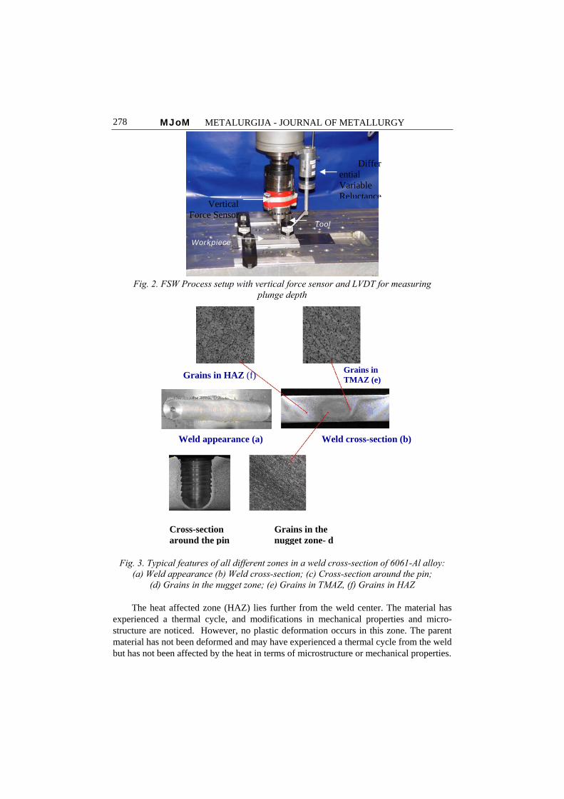
The examination of many friction stir welds in aluminum alloys has revealed that there are four major microstructural zones, as indicated in Fig. 3. The microstructure of the weld is complex and highly dependent on the position within the welded zone. The fine grains are found in the nugget zone, in contrast to the TMAZ and HAZ zones where coarsened grains are observed. In addition, it has been suggested that the area immediately below the tool shoulder should be given a separate category, as the grain structure is often different in that area.
The thermo-mechanically affected zone (TMAZ) is an area that has been plastically deformed by the friction stir welding tool, and the heat from the process will also have exerted some influence on the material. As aluminum behaves in a different manner to most other materials, it is possible to get significant plastic strain without recrystallization in this region, and there is a distinct boundary between the recrystallized zone and the deformed zones of the TMAZ. In other materials, the distinct recrystallized region (the nugget) is absent, and the whole TMAZ appears to be recrystallized.
MJoM METALURGIJA - JOURNAL OF METALLURGY 278
Fig. 2. FSW Process setup with vertical force sensor and LVDT for measuring
plunge depth
Fig. 3. Typical features of all different zones in a weld cross-section of 6061-Al alloy: (a) Weld appearance (b) Weld cross-section; (c) Cross-section around the pin;
(d) Grains in the nugget zone; (e) Grains in TMAZ, (f) Grains in HAZ The heat affected zone (HAZ) lies further from the weld center. The material has
experienced a thermal cycle, and modifications in mechanical properties and micro-structure are noticed. However, no plastic deformation occurs in this zone. The parent material has not been deformed and may have experienced a thermal cycle from the weld but has not been affected by the heat in terms of microstructure or mechanical properties.
Weld cross-section (b) Weld appearance (a)
Cross-section around the pin
Grains in the nugget zone- d
Grains in HAZ (f) Grains in TMAZ (e)
Vertical Force Sensor
Differential Variable Reluctance
Tool
Workpiece

AN OVERVIEW OF R&D WORK IN FRICTION STIR WELDING AT SMU 279The design of the FSW tool is at the heart of this remarkable welding process. This
technique uses a non-consumable steel welding tool to generate frictional heat at the point of welding and to produce the gross plastic deformation of the workpiece material while the material is in the solid phase, resulting in complex mixing across the joint. The tool, which consists of the shank, shoulder, and pin, (See Fig. 4, 5), rotates along the longitudinal axis in a conventional milling machine. The pin is equipped with a thread that assures that the plastically deformed material is fully distributed around the pin.
Fig. 4. Schematic of the friction stir welding tool [20]
Fig. 5. A few of the tools developed and used for FSW at RCAM
SENSING THE FSW PROCESS
From the standpoint of cost optimization, it is essential to monitor the welding process itself so that the potential to produce a bad weld can be detected and avoided by regulating the process parameters. From the concept of FSW and the results obtained so far [2-4], it has been revealed that the weld quality depends very much on the welding parameters and tool conditions. These parameters are in turn affected by machine setup and also by the material properties. To ensure weld quality, it is beneficial to control these parameters automatically by incorporating an in-process monitoring system.
Similar monitoring attempts have been made on friction welding, and have been successfully implemented in the friction welders. Dews [5] incorporated a system to

MJoM METALURGIJA - JOURNAL OF METALLURGY 280
control the axial force and the resulting friction torque consisting of a servo valve, a servo regulator, and a current value measuring element. Ellsworth [6] has described a sophisticated system built by Advanced Technology Inc., which worked by controlling the burnoff rate, distance, and forge distance in friction welding. A robot has been introduced in FSW and has successfully been used in the welding of dissimilar thickness butt welds, and it shows the potential for achieving 3-D joint configurations [7-9]. The controlling methodology requires a real-time monitoring technology for the weld quality and the manufacturing process. Acoustic emission (AE), temperature, force, and torque monitoring may provide a robust tool to implement monitoring this process. A corresponding force and torque measuring system has been developed at RCAM.
ACOUSTIC EMISSION SENSING
Acoustic emission (AE) is a transient elastic wave that is generated during the rapid release of energy from localized sources within a material [10]. It is observed only while the energy is being released and may be detected with a suitable sensor. The source of these emissions in metals is closely associated with the dislocation movement accompanying plastic deformation, and the initiation and extension of cracks in a structure under stress. Other sources of AE are: phase transformation, thermal stresses, cool down cracking, and stress build-up.
In general, the acoustic emission signals can be classified into two types, the continuous type and the burst type. The continuous type represents the plastic deformation in ductile materials, while the burst type characterizes unsteady processes. Because, the friction stir welding process is very robust in terms of welding parameters, it usually produces signals that represent burst acoustic emissions.
MONITORING WELD QUALITY
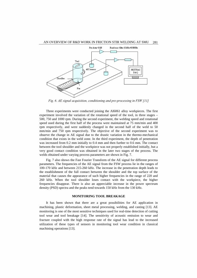
Acoustic emission sensing is mostly based on processing signals with a frequency range of 10 kHz to about 800 kHz for machining processes with cutting operations [12]. From our preliminary studies, the frequency range assumed for the friction stir welding process is between 100 kHz and 300 kHz. Before the start of the process, the AE test results recorded on the butted plates with the machine in the running mode were found to contain noises due to machine vibration at amplitudes below 45 dB. In order to filter out the mechanical noise, a band pass filter was used for collecting signals in the range of 10 kHz to 400 kHz during the FSW process. The AE signal data from the two sensors (channel 1 and channel 2) were found to have the same frequencies but different amplitudes. The generated acoustic emission data during welding was collected for the entire welding process, progressively amplified through the preamplifier with a 40 dB gain, passed through 10 kHz-400 kHz band pass filter to filter-out the low frequency noise, and transmitted to the signal processor as shown in Fig. 6. The AE voltage output was sampled by the MISTRAS data acquisition system at a rate of 1 megasamples per second (MSPS).
AN OVERVIEW OF R&D WORK IN FRICTION STIR WELDING AT SMU 281
Fig. 6. AE signal acquisition, conditioning and pre-processing in FSW [11]
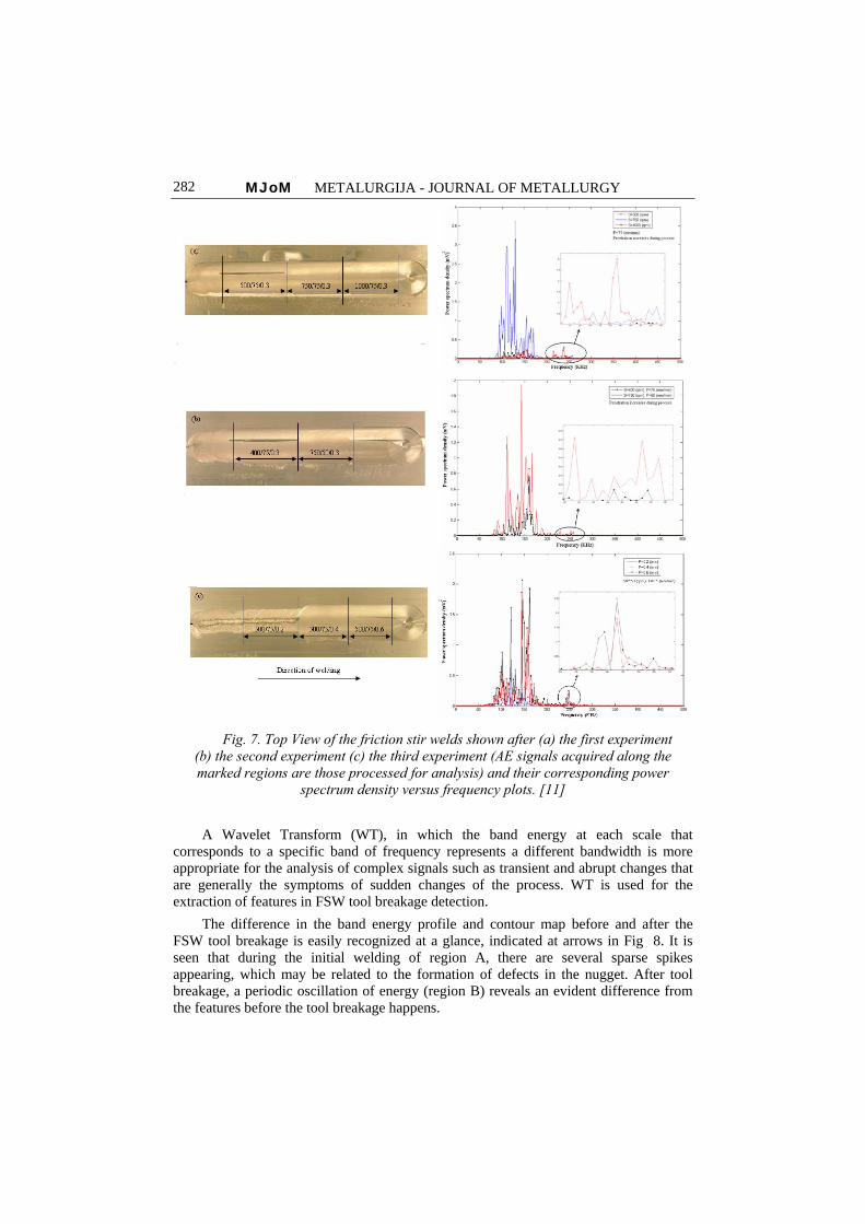
Three experiments were conducted joining the Al6061 alloy workpieces. The first
experiment involved the variation of the rotational speed of the tool, in three stages – 500, 750 and 1000 rpm. During the second experiment, the welding speed and rotational speed used during the first half of the process were maintained at 75 mm/min and 400 rpm respectively, and were suddenly changed in the second half of the weld to 50 mm/min and 750 rpm respectively. The objective of the second experiment was to observe the change in AE signal due to the drastic variation in the thermo-mechanical condition that exists in the weld zone. In the third experiment, the depth of penetration was increased from 0.2 mm initially to 0.4 mm and then further to 0.6 mm. The contact between the tool shoulder and the workpiece was not properly established initially, but a very good contact condition was obtained in the later two stages of the process. The welds obtained under varying process parameters are shown in Fig. 7.
Fig. 7 also shows the Fast Fourier Transform of the AE signal for different process parameters. The frequencies of the AE signal from the FSW process lie in the ranges of 100-170 kHz and between 215-260 kHz. The increase in the penetration depth leads to the establishment of the full contact between the shoulder and the top surface of the material that causes the appearance of such higher frequencies in the range of 220 and 260 kHz. When the tool shoulder loses contact with the workpiece, the higher frequencies disappear. There is also an appreciable increase in the power spectrum density (PSD) spectra and the peaks tend towards 150 kHz from the 130 kHz.
MONITORING TOOL BREAKAGE
It has been shown that there are a great possibilities for AE application in machining, plastic deformation, sheet metal processing, welding, and casting [13]. AE monitoring is one of the most sensitive techniques used for real-time detection of cutting tool wear and tool breakage [14]. The sensitivity of acoustic emission to wear and fracture coupled with the high response rate of the signal has lead to the increased utilization of these types of sensors in monitoring tool wear condition in classical machining operations [13].
MJoM METALURGIJA - JOURNAL OF METALLURGY 282
Fig. 7. Top View of the friction stir welds shown after (a) the first experiment
(b) the second experiment (c) the third experiment (AE signals acquired along the marked regions are those processed for analysis) and their corresponding power
spectrum density versus frequency plots. [11] A Wavelet Transform (WT), in which the band energy at each scale that
corresponds to a specific band of frequency represents a different bandwidth is more appropriate for the analysis of complex signals such as transient and abrupt changes that are generally the symptoms of sudden changes of the process. WT is used for the extraction of features in FSW tool breakage detection.
The difference in the band energy profile and contour map before and after the FSW tool breakage is easily recognized at a glance, indicated at arrows in Fig 8. It is seen that during the initial welding of region A, there are several sparse spikes appearing, which may be related to the formation of defects in the nugget. After tool breakage, a periodic oscillation of energy (region B) reveals an evident difference from the features before the tool breakage happens.
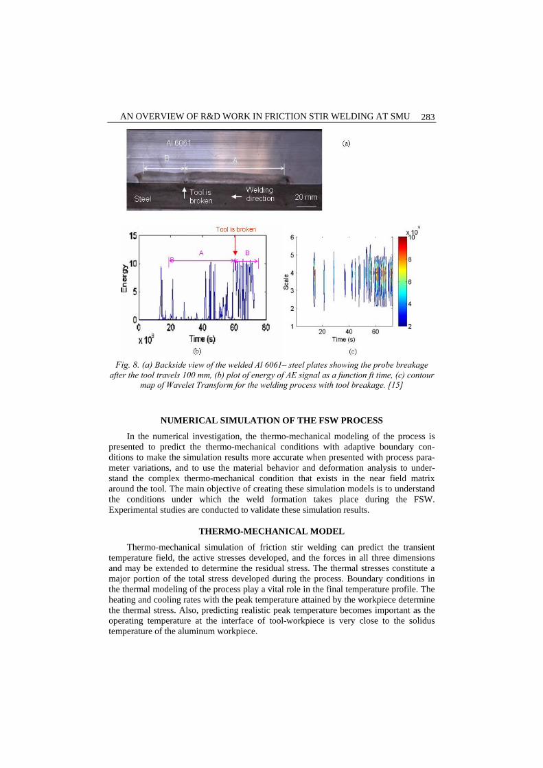
AN OVERVIEW OF R&D WORK IN FRICTION STIR WELDING AT SMU 283
Fig. 8. (a) Backside view of the welded Al 6061– steel plates showing the probe breakage
after the tool travels 100 mm, (b) plot of energy of AE signal as a function ft time, (c) contour map of Wavelet Transform for the welding process with tool breakage. [15]
NUMERICAL SIMULATION OF THE FSW PROCESS
In the numerical investigation, the thermo-mechanical modeling of the process is presented to predict the thermo-mechanical conditions with adaptive boundary con-ditions to make the simulation results more accurate when presented with process para-meter variations, and to use the material behavior and deformation analysis to under-stand the complex thermo-mechanical condition that exists in the near field matrix around the tool. The main objective of creating these simulation models is to understand the conditions under which the weld formation takes place during the FSW. Experimental studies are conducted to validate these simulation results.
THERMO-MECHANICAL MODEL
Thermo-mechanical simulation of friction stir welding can predict the transient temperature field, the active stresses developed, and the forces in all three dimensions and may be extended to determine the residual stress. The thermal stresses constitute a major portion of the total stress developed during the process. Boundary conditions in the thermal modeling of the process play a vital role in the final temperature profile. The heating and cooling rates with the peak temperature attained by the workpiece determine the thermal stress. Also, predicting realistic peak temperature becomes important as the operating temperature at the interface of tool-workpiece is very close to the solidus temperature of the aluminum workpiece.

MJoM METALURGIJA - JOURNAL OF METALLURGY 284
This section presents a finite element thermo-mechanical model with mechanical tool loading that considers a uniform value for contact conductance and that is used to predict the stress at the workpiece and at the backing plate interface. These pressure distribution contours are used for defining the non-uniform adaptive contact conductance, which is in turn used in the thermal model for predicting the thermal history in the workpiece. The thermo-mechanical model is then used to predict stress development in friction stir welding.
The main heat source in FSW is generally considered to be the friction between the rotating tool and the welded workpieces, and the "cold work" in the plastic deformation of the material in the vicinity of the tool. The heat generation from the plastic deformation of the material is considered to some extent in the model with the use of a variable friction coefficient and it is therefore not explicitly accounted for as a heat source. The heat is generated at the interface of tool shoulder and workpiece due to friction and plastic deformation.
Frictional heat generated at shoulder (85-90% of total heat):
)RR)(RF)(
60N2(
32q 2
p2s2
s
n1 −=
πμ (1)
Heat due to plastic deformation (10-15% of total heat):
Vq pl2 εησ &= (2)
Heat into workpiece from shoulder and pin:
1qkk
kqwT
ww += (3)
The heat generated at the surface of the tool is transferred into the tool following Fourier’s law of heat conduction. The heat transfer equation for the tool in a static coordinate system is
⎥⎥⎦
⎤
⎢⎢⎣
⎡
∂
∂+
∂
∂+
∂
∂′+=∂∂
2
2
2
2
2
2
zT
yT
xTkQ
tTc &ρ (4)
where T is the temperature, c is heat capacity, ρ is the density and k ′ are heat conductivities that vary with temperature in the calculations. The aluminum workpiece is considered to have isotropic material properties, and so the same value of thermal conductivity is used for all three directions.
The coordinate system moves over the workpiece in the positive x-axis at a velocity vx. The heat transfer equation for the workpiece is
⎥⎥⎦
⎤
⎢⎢⎣
⎡
∂
∂+
∂
∂+
∂
∂′+=⎟⎠⎞
⎜⎝⎛
∂∂
+∂∂
2
2
2
2
2
2
xzT
yT
xTkQ
xTv
tTc &ρ (5)

AN OVERVIEW OF R&D WORK IN FRICTION STIR WELDING AT SMU 285During the penetration phase, the rotating pin penetrates into the workpiece until the
tool shoulder comes in contact with the workpiece. The penetration speed is chosen to be 2.22 mm/s in the model, and the corresponding penetration time is approximately 2.64 sec. Fig. 9 presents cross-sectional views of the calculated temperature contours in the workpiece and tool at different times during the penetration and pullout of the pin.
a)
b) Fig. 9. Temperature-time history for tool and workpiece during (a) tool pin penetration
and (b) tool pullout (V = 5.5 mm/s, ω = 344 rpm)[16]
Fig. 10. Calculated temperature field distribution for the integrated tool-workpiece
model in the longitudinal section along the joint line (V = 5.5 mm/s, ω = 344 rpm)[15] The longitudinal view of the calculated temperature field distribution along the joint
line at the end of process is shown in Fig. 10. The results at the position of the thermocouple in the simulated thermal profile at the end of the weld process is compared with the experimental results and shown in Fig. 11. It can be seen that the highest temperature attained is almost the same for both process simulations and for the experimentally obtained value. But the gradient of temperature built-up in the workpiece is different for the simulation cases, with adaptive contact conductance model giving results which closely match the experimental measurements.

MJoM METALURGIJA - JOURNAL OF METALLURGY 286
050
100150200250300350400450
1 5 9 13 17 21 25 29 33 37 41 45 49 53 57 61 65
Time (sec)
Tem
pera
ture
(deg
-C) FEM Value with uniform
contact conductance
FEM Value with non-uniform contactconductanceMeasured Value
Fig. 11. Comparison of the modeled and the measured temperature history
for workpiece Temperature-time profile for thermocouple location 6mm from the joint line (V = 133 mm/min, ω = 344 rpm) [16]
Fig.12 shows the stress profile of the welded plate in three directions when the tool reaches the middle of the workpiece. Fig.12a shows the active stress in the longitudinal direction (X direction). It can be seen that the stress distribution in front of the plate (marked by A) is very low as it has not yet been affected by thermal stress or by structural loading. In the area marked by C, it is observed that the tensile stress starts to increase due to the mechanical force in the horizontal direction and reaches maximum at the tool. The region behind the tool marked by D has a compressive stress with the maximum value just behind the tool. The thermal expansion and constraint on the sides by the fixture results in compressive stress in this area. This stress extends to the region near the edge behind the tool. In the region marked by B, the compressive stress changes into tensile stress due to the contraction of the workpiece as it cools, which is restricted by the fixture clamps to either side of the weld.
In Fig.12b, the active stress in the transverse direction is shown (Y direction). There is very little tensile stress before the tool in the transverse direction as the stress development is due to tool movement along the X axis, which mainly affects stress creation in the longitudinal direction. The area behind the tool has a high compressive stress because of the thermal stress leading to expansion of workpiece which is constrained by the fixture on both sides. The region D has a tensile stress as the shrinkage of the workpiece has started to take place with constraints at the ends.
In Fig.12c, it may be noted that the stress in the vertical direction is negligible along the edges of the workpiece (region B) while it is compressive in the remaining regions. There is a high compressive stress developed in the vertical direction on the tool as it moves forward. The region behind the tool exhibits a tensile stress because the surface of the tool is made have a complete contact with the workpiece. This tensile stress may therefore be an artifact of the simulation and may not be so prominent in reality.

AN OVERVIEW OF R&D WORK IN FRICTION STIR WELDING AT SMU 287
a)
b)
c)
Fig. 12. Predicted stress distribution (N/mm2) in the welded plate in three directions half way through the weld in (a) x axis (longitudinal direction)
(b) y axis (lateral direction) (c) z axis (vertical direction) [16]
EXPLICIT ANALYSIS FOR MATERIAL FLOW
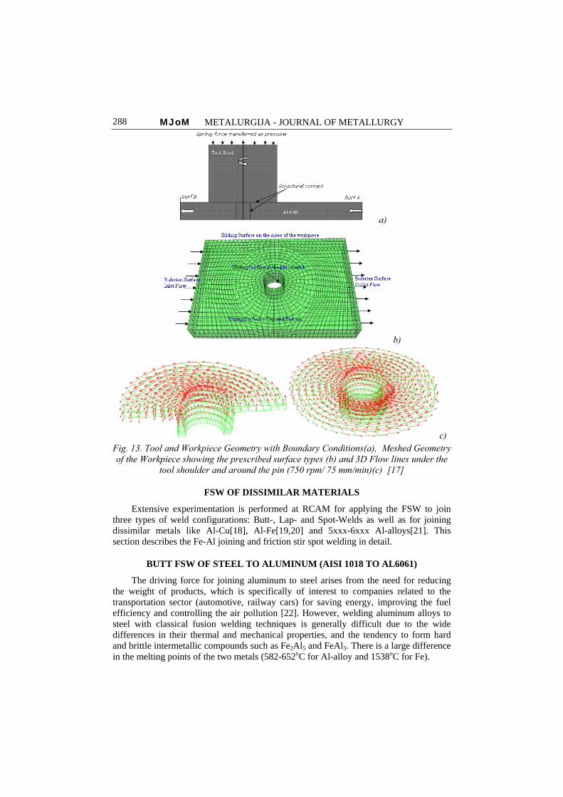
A steady thermo-mechanical state attained during the FSW in the local deformation zone is modeled using explicit finite element analysis. An explicit solver with ALE formulation is able to model the FSW process with large material deformation by using the Johnson-Cook plasticity law, and by modeling the material behavior in different temperature zones (above and below the recrystallization temperature). An adaptive meshing technique helps in remeshing the model when the material undergoes large deformation, as does the use of surfaces such as Lagrangian, Eulerian and Sliding.
The temperature field that produces the observed plunge of the tool into the workpiece for an applied pressure is predicted by this model. The model included the material motion in the workpiece during the weld period. The predicted overall temperatures, deformed shapes and streamlines are reasonable considering the assumptions made (Fig. 13).
AB CD
ABD C
A
B
MJoM METALURGIJA - JOURNAL OF METALLURGY 288
a)
b)
c) Fig. 13. Tool and Workpiece Geometry with Boundary Conditions(a), Meshed Geometry of the Workpiece showing the prescribed surface types (b) and 3D Flow lines under the
tool shoulder and around the pin (750 rpm/ 75 mm/min)(c) [17]
FSW OF DISSIMILAR MATERIALS
Extensive experimentation is performed at RCAM for applying the FSW to join three types of weld configurations: Butt-, Lap- and Spot-Welds as well as for joining dissimilar metals like Al-Cu[18], Al-Fe[19,20] and 5xxx-6xxx Al-alloys[21]. This section describes the Fe-Al joining and friction stir spot welding in detail.
BUTT FSW OF STEEL TO ALUMINUM (AISI 1018 TO AL6061)
The driving force for joining aluminum to steel arises from the need for reducing the weight of products, which is specifically of interest to companies related to the transportation sector (automotive, railway cars) for saving energy, improving the fuel efficiency and controlling the air pollution [22]. However, welding aluminum alloys to steel with classical fusion welding techniques is generally difficult due to the wide differences in their thermal and mechanical properties, and the tendency to form hard and brittle intermetallic compounds such as Fe2Al5 and FeAl3. There is a large difference in the melting points of the two metals (582-652oC for Al-alloy and 1538oC for Fe).

AN OVERVIEW OF R&D WORK IN FRICTION STIR WELDING AT SMU 289
The present study deals with joining the steel and the aluminum alloy using the FSW and understanding the process mechanism with help of experimental results, the macrostructure and the microstructure of the weld. The joining methodology is derived from friction stir welding (FSW) with an adjustable location of the tool pin with respect to the joint line. The plates of Al 6061-T6 and cold-rolled AISI 1018 steel 6-mm thick are friction stir welded along the butted joint (Fig. 14).
(c) Fig. 14. (a) Schematic presentation of FSW of Al-alloy to Steel(a), Location of pin in
relation to the butt line of the welded plates(b), and top view of the welded Fe-Al plates with a tool offset of 2 mm (500 rpm and 130 mm/min)(c) [19]
A specially designed tool made of Tungsten-Rhenium (W-Re) with a pin consisting of a triflute with edges that act as cutting edges is used for the experimentation. The combined effect of the mechanical stirring action during the friction stir welding in the plasticized aluminum side and the sheared-off particles of steel by hot cutting with the pin edges developed a heterogeneous structure of the weld zone (Fig. 15).
The obtained nugget is made of a metal matrix composite material that consists of the steel chips sheared-off from the steel plate and formed intermetallic compounds stirred through the matrix of aluminum.
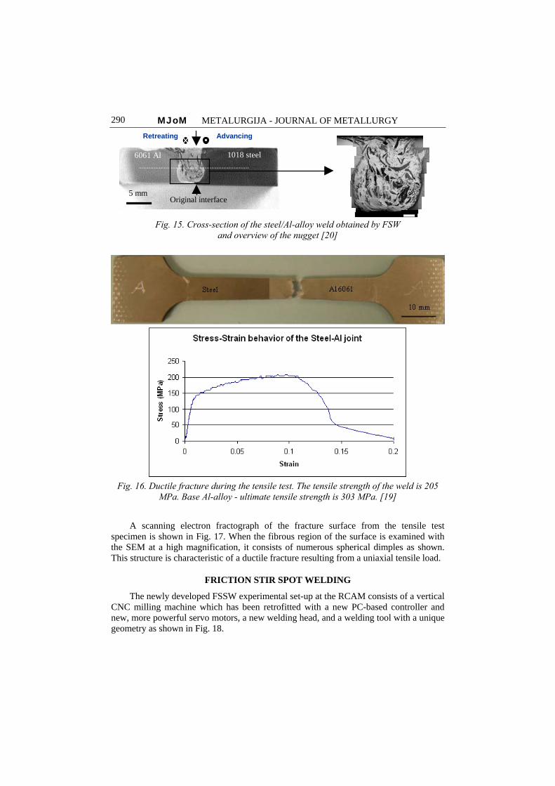
The tensile test demonstrated that a fracture occurred at the boundary between the Thermo-Mechanically Affected Zone (TMAZ) and the Heat Affected Zone (HAZ) in the base Al-alloy rather than across the nugget or along the interface between the nugget and the steel side, indicating a sound weld of good quality. The tensile strength of the non-heat treated weld is 205 MPa, about 65% of the base Al-alloy strength (Fig. 16).
MJoM METALURGIJA - JOURNAL OF METALLURGY 290
6061 Al 1018 steel
Original interface 5 mm
AdvancingRetreating
1 Fig. 15. Cross-section of the steel/Al-alloy weld obtained by FSW
and overview of the nugget [20]
Fig. 16. Ductile fracture during the tensile test. The tensile strength of the weld is 205
MPa. Base Al-alloy - ultimate tensile strength is 303 MPa. [19] A scanning electron fractograph of the fracture surface from the tensile test
specimen is shown in Fig. 17. When the fibrous region of the surface is examined with the SEM at a high magnification, it consists of numerous spherical dimples as shown. This structure is characteristic of a ductile fracture resulting from a uniaxial tensile load.
FRICTION STIR SPOT WELDING
The newly developed FSSW experimental set-up at the RCAM consists of a vertical CNC milling machine which has been retrofitted with a new PC-based controller and new, more powerful servo motors, a new welding head, and a welding tool with a unique geometry as shown in Fig. 18.

AN OVERVIEW OF R&D WORK IN FRICTION STIR WELDING AT SMU 291
Fig. 17. Scanning electron fractograph showing (a) the macrograph of the fracture
surface and (b) the micrographs of 1 and 2 surfaces showing spherical dimples characteristic of ductile fracture resulting from uniaxial tensile loads. [19]
(a) (b)
Fig. 18 (a) The RCAM FSSW Welding Head and (b) pin tool. [23] The sequence of events which occurs when a weld is made is shown in Fig. 19.
Initially, the welding head is above the area to be welded (position A). Rotation of the tool is initiated, and the welding head is brought into contact with the workpiece (position B). The tool is then pressed into the workpiece while the welding head is held in place (position C). The tool is then retracted (position D), and finally the welding head is moved away from the workpiece (position E).

MJoM METALURGIJA - JOURNAL OF METALLURGY 292
A B C D E
PIN AND SHOULDER TOOL
WELDING HEAD
Fig. 19. Sequence of operations for the FSSW welding head and for the tool. [23]
Fig. 20 shows the macrograph of a weld created using a conventional tool with a single pin and the newly designed tool characterized with a number of pins. The welds are created with a rotational speed of 1200 RPM and a plunging speed of 75mm/min. It could be seen from Fig. 20 that the volume of plastic flow around the pin could be fairly small using the conventional tool compared to the proposed one, so that the welded area between the top and bottom plates could also be small. This may be one of the reasons for the lower performance of the spot welds created with a conventional tool as compared to the welds created with the new tool.
a)
b) Fig. 20 Macrograph showing a FSSW of AA 6022-T4 using (a) conventional tool and (b) specially designed tool. [23]
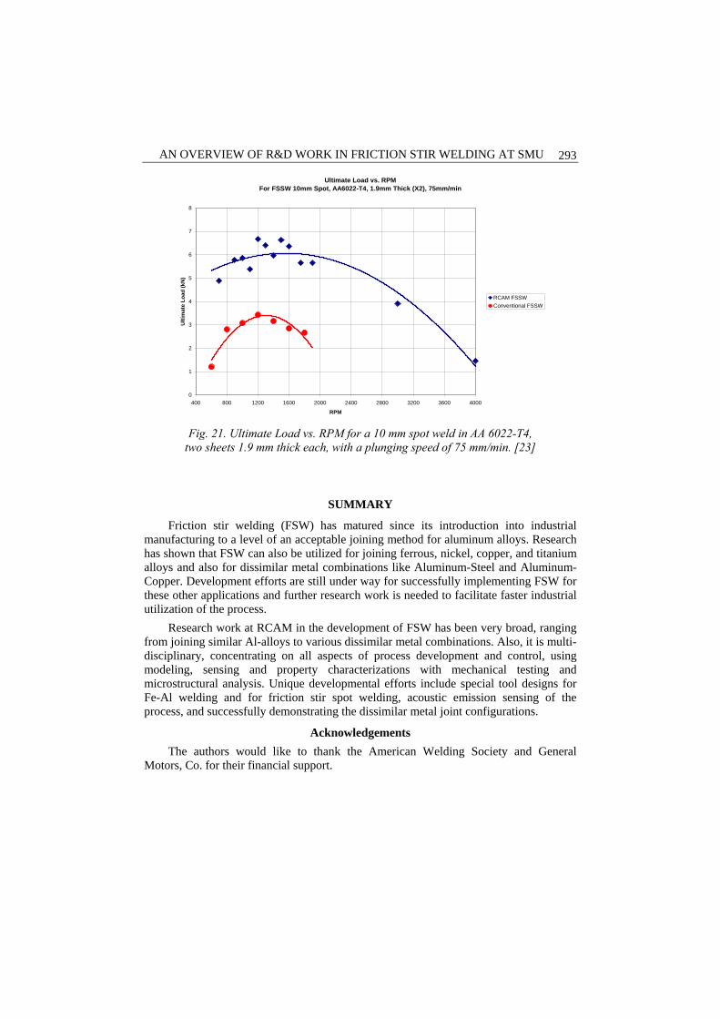
A series of experiments are conducted with the rotating speed of the tool varying from 500 to 4000 rpm, while the plunging speed and programmed plunge depth are kept constant. The results of the tensile-shear tests are shown in Fig. 21. Welds using a conventional tool, with the same plunging speed of 75 mm/min., are included in the same Figure for comparison. It could be seen from Fig. 21 that the RCAM FSSW process produces a very strong weld for rotational speeds from 500 to 3000 RPM, with a peak ultimate load of 6.67 kN at 1200 RPM. For the conventional tool, the peak ultimate load is also found to be at 1200 RPM, but the peak ultimate load is 3.42 kN. In this case, the RCAM FSSW process produces a spot weld with nearly twice the ultimate load in a tensile-shear test than that of a spot weld created using the conventional tool.
AN OVERVIEW OF R&D WORK IN FRICTION STIR WELDING AT SMU 293
Ultimate Load vs. RPMFor FSSW 10mm Spot, AA6022-T4, 1.9mm Thick (X2), 75mm/min
0
1
2
3
4
5
6
7
8
400 800 1200 1600 2000 2400 2800 3200 3600 4000
RPM
Ulti
mat
e Lo
ad (k
N)
RCAM FSSWConventional FSSW
Fig. 21. Ultimate Load vs. RPM for a 10 mm spot weld in AA 6022-T4,
two sheets 1.9 mm thick each, with a plunging speed of 75 mm/min. [23]
SUMMARY
Friction stir welding (FSW) has matured since its introduction into industrial manufacturing to a level of an acceptable joining method for aluminum alloys. Research has shown that FSW can also be utilized for joining ferrous, nickel, copper, and titanium alloys and also for dissimilar metal combinations like Aluminum-Steel and Aluminum-Copper. Development efforts are still under way for successfully implementing FSW for these other applications and further research work is needed to facilitate faster industrial utilization of the process.
Research work at RCAM in the development of FSW has been very broad, ranging from joining similar Al-alloys to various dissimilar metal combinations. Also, it is multi-disciplinary, concentrating on all aspects of process development and control, using modeling, sensing and property characterizations with mechanical testing and microstructural analysis. Unique developmental efforts include special tool designs for Fe-Al welding and for friction stir spot welding, acoustic emission sensing of the process, and successfully demonstrating the dissimilar metal joint configurations.
Acknowledgements The authors would like to thank the American Welding Society and General
Motors, Co. for their financial support.

MJoM METALURGIJA - JOURNAL OF METALLURGY 294
REFERENCES
[1] W.J. Arbegast, “Friction stir welding: After a decade of development”, Welding Journal, March 2006, pp.28-35.
[2] T. Hashimoto, S. Jyogan, K. Nakata, Y. G. Kim, and M. Ushio, FSW joints of high strength aluminum alloy, , 1st International Symposium on Friction Stir Welding, held at the Rockwell Science Center, Thousand Oaks, California, 14-16 June 1999
[3] G. Biallas, R. Braun, C. D. Donne, G. Staniek, and W. A. Kaysser, Mechanical properties and corrosion behavior of friction stir welds, 1st International Symposium on Friction Stir Welding, held at the Rockwell Science Center, Thousand Oaks, California, 14-16 June 1999
[4] R. A. Prado, L. E. Murr, D. J. Shindo and K. F. Soto, Tool wear in the friction-stir welding of aluminum alloy 6061+20% Al2O3: a preliminary study, Scripta Materiallia, 2001, 45:75-80.
[5] P. Drews, et al. Automatic control of friction welding process, International institute of welding commission III, document No. III 415-71, 1971.
[6] G. S. Ellsworth Advances in friction weld monitoring and control, SME technical paper No. AD 78-748, 1978.
[7] C. B. Smith, Robotic friction stir welding using a standard industrial robot, 2nd FSW Symposium , 26-28 June 2000 - Quality Hotel 11, Gothenburg, Sweden.
[8] Strombeck A von, C Schilling, J F dos Santos, Robotic friction stir welding: tool technology and applications, 2nd FSW Symposium, 26-28 June 2000, Gothenburg, Sweden.
[9] S. Brinckmann, Strombeck A. von, C. Schilling, J. F. dos Santos, D. Lohwasser, M. Koçak, Mechanical and toughness properties of robotic FSW repair welds in 6061-T6 aluminium alloys, 2nd FSW Symposium, 26-28 June 2000, Gothenburg, Sweden.
[10] R. K. Miller, P. Mclntire, Acoustic Emission, ASNT Nondestructive Testing Handbook, Vol. 5: Acoustic Emission Testing, published by American Society for Nondestructive Testing, 1987.
[11] [11] V. Soundararajan, H. Atharifar and R. Kovacevic, “Monitoring and processing of acoustic emission signals from friction stir welding process”, IMechE Journal of Engineering Manufacture, Feb 2006.
[12] XiaoQi, C., Hao, Z., and Wildermuth, D., In-process tool monitoring through acoustic emission sensing. SIMTech Technical Report (AT/01/014/AMP), 2001.
[13] D.A. Dornfeld, “Design and Implementation of In-process Sensors for the Control of Presicion Manufacturing Processes”, Sensing for Materials Characterization, Processing, and Manufacturing, Vol. I, Editors: G. Birnbaum and B.A. Auld, The American Society for nondestructive Testing, Inc., 1998.
[14] D. Dornfeld, Application of acoustic emission techniques in manufacturing, NDT & E international 25(1999) 259-269.
AN OVERVIEW OF R&D WORK IN FRICTION STIR WELDING AT SMU 295
[15] Chen, C., Kovacevic, R., Jandric, D., Wavelet transform analysis of acoustic emission in monitoring friction stir welding of 6061 aluminum. International Journal of Machine Tools and Manufacture, October 2003, 43(13), 1383-1390.
[16] V. Soundararajan, S. Zekovic and R. Kovacevic, “Thermo-mechanical model with adaptive boundary conditions for friction stir welding of AL6061”, International Journal of Machine tools and Manufacture, Nov 2005.
[17] V. Soundararajan and R. Kovacevic, “Simulation of temperature field in friction stir welding using material behavior and deformation analysis”, Contemporary achievements in Mechanics, Manufacturing and Materials Science, Poland, Dec 2005.
[18] J. Ouyang, E. Yarrapareddy, and R. Kovacevic, "Microstructural evolution in the friction stir welded 6061 aluminum alloy (T6-temper condition) to copper", Journal of Materials Processing Technology, v 172, n 1, Feb 20, 2006, p 110-122.
[19] V. Soundararajan, M. Valant and R. Kovacevic, “Joining of Aluminum Alloy to Steel using Friction Stir Welding”, International Journal of Machine Tools and Manufacture, April 2006.
[20] C. Chen, and R. Kovacevic, "Joining of Al 6061 alloy to AISI 1018 steel by combined effects of fusion and solid state welding", International Journal of Machine Tools and Manufacture, v 44, n 11, September, 2004, p 1205-1214.
[21] V. Soundararajan, E. Yarrapareddy and R. Kovacevic, “Investigation of friction stir lap welding of aluminum alloys AA 5182 and AA 6022”, ASM Journal of Materials Engineering and Performance, Mar 2006.
[22] Cole, G. S. and Sherman, A. M., “Lightweight materials for automotive applications”, Materials Characterization, 35, 1995, p. 3-9.
[23] M. Valant, and R. Kovacevic, "A Novel Tool Design for Friction Stir Spot Welding", Session:6, 7th Int’l Conf. on Trends in Welding Research, Pine Mountain, GA, May 16-20, 2005.