Embed Size (px)
Citation preview

An Ontology Based Test Case Generation Framework
Hapuarachchige Nishadi Anjalika
Index No: 13000098
Meregngnage Thisara Yasantha Salgado
Index No: 13001061
Prabhavi Ishara Siriwardhana
Index No: 13001159
University of Colombo
School of Computing
2018

ii
Declaration
We certify that this dissertation does not incorporate, without acknowledgment, any material
previously submitted for a degree or diploma in any university and to the best of our knowledge and
belief, it does not contain any material previously published or written by another person or ourselves
except where due reference is made in the text. We also hereby give consent for our dissertation, if
accepted, be made available for photocopying and for interlibrary loans, and for the title and abstract
to be made available to outside organizations.
Candidate Name: H.N.Anjalika (2013/CS/009)
………………………………………………
Signature of Candidate Date: …………………….
Candidate Name: M.T.Y.Salgado (2013/CS/106)
………………………………………………
Signature of Candidate Date: …………………….
Candidate Name: P.I.Siriwardhana (2013/CS/115)
………………………………………………
Signature of Candidate Date: …………………….
This is to certify that this dissertation is based on the work of Ms. H.N.Anjalika, Mr.
M.T.Y.Salgado and Ms. P.I.Siriwardhana under our supervision. The dissertation has been
prepared according to the format stipulated and is of the acceptable standard.
Supervisor Name: Prof. N.D. Kodikara
………………………………………………
Signature of Supervisor Date: …………………….
Co-Supervisor Name: Dr. A.R. Weerasinghe
………………………………………………
Signature of Co-Supervisor Date: …………………….

iii
Abstract
Software testing is a crucial part of the software development life cycle which ensures
that the developed product meets the user requirements. Currently, test cases which come under
the test design phase are written almost manually based on user requirements in the companies
who follow Agile methodology. This tedious manual process requires 40-70% of the software test
life cycle which has affected on cost, time and effort factors due to the frequent changes in
requirements and having different terminologies. Companies that follow Agile practices along
with Behaviour Driven Development approach capture requirements through user stories written
in natural language. Representation of requirements in a formalized way affect the high
effectiveness of requirement management by reducing the time and cost factors. Ontology is such
an approach where it leads to knowledge reuse for sharing common terminologies and concepts
by modelling the requirement domain knowledge constructed with the reasoning behaviour. To
achieve automated test case generation, an Ontology-based system has been developed with the
purpose of maximising semantic technology representation for the requirement domain.
Instead of writing test cases manually, this thesis investigates a practical solution for
automatically generating test cases within an Agile software development using natural language-
based user stories with an Ontology-based approach for requirement representation. To establish
the feasibility, a framework has been developed that uses NLP techniques which can auto-
generate functional positive test cases from the requirements provided through user stories, based
on that developed Ontology. The use of an Ontology knowledge base for the software
requirement domain has given a better manageability of the requirement domain while the
framework reduces the effort required to create the test cases. Also the thesis has introduced a
new concept as an Ontologist role into the software development process for the evolvement of
the Ontology model. Results from the system evaluation and user evaluation are presented in this
thesis. Comparing these results with the test cases taken from the industry which are manually
written, the system provides a considerable amount of test coverage for the positive test cases.

iv
Acknowledgement
We take this opportunity to express our sincere appreciation towards all the people who has
sacrificed their time all along this thesis and guiding us to concentrate on our work.
First we would like to express our sincere gratitude to our supervisor, Prof. N. D. Kodikara
for the continuous support throughout our research study and for guiding us towards the right
path at time when we were blindly moving. We would like to thank him for the enormous
knowledge provided and motivation. Besides our supervisor, we would like to give special
appreciation to Senior Lecturer Dr. A.R. Weerasinghe as our co-supervisor for his help,
useful comments and cooperation during the project.
Moreover, our sincere gratitude goes to our examiners Senior Lecturer Dr. H.A. Caldera and
Senior Lecturer Mr. G.P.Seneviratne for their valuable and encouraging comments with
respect to the improvements of the research.
Furthermore, our sincere appreciation goes to Dr. Kosala Yapa Mudiyanselage, Professional
in Ontology studies for the support and experience that given to the research study. Also we
would like to express sincere gratitude to Mr. Dharshana Warusavitharana, Efficiency
Engineer at WSO2 and Mr. Nadeesha Gamage, Lead Solutions Engineer at WSO2 for the
technological support and industrial experience given to the project.
Moreover, we thank our fellow batch mates who works in the field of Software Quality
Assurance for the support given by involving in user evaluation process of the project.
Last but not the least; we would like to express our heartiest gratitude towards our family
members for understanding each and every situation and for being our pillars of success.

v
Contents
List of Figures ................................................................................................................................... ix
List of Tables .................................................................................................................................... xi
Abbreviations .................................................................................................................................. xii
Chapter 1 ............................................................................................................................................... 1
1.1 Overview ...................................................................................................................................... 2
1.2 Motivation .................................................................................................................................... 3
1.3 Research Questions ..................................................................................................................... 6
1.4 Aim and Objectives ..................................................................................................................... 7
1.5 Scope of the project ..................................................................................................................... 7
1.6 Justification as product based .................................................................................................... 8
1.7 Overview of methodology ........................................................................................................... 9
1.8 Outline of the thesis .................................................................................................................. 10
Chapter 2 ............................................................................................................................................. 11
2.1 Introduction ............................................................................................................................... 11
2.2 Software Testing ........................................................................................................................ 11
2.2.1 Concepts of software testing .............................................................................................. 12
2.2.2 Importance of software testing ......................................................................................... 12
2.2.3 Test Case ............................................................................................................................. 13
2.2.4 User story ............................................................................................................................ 14
2.3 Software Development Industry in Sri Lanka........................................................................ 15
2.4 Automated test case generation ............................................................................................... 16
2.4.1 Requirement based test case generation .......................................................................... 16
2.4.2 Model based test case generation ...................................................................................... 17
2.4.3 Source code based test case generation ............................................................................ 18
2.5 Entity extraction using Natural Language Processing .......................................................... 19
2.5.1 Stanford CoreNLP ............................................................................................................. 19
2.5.2 Triplet Extraction .............................................................................................................. 21
2.6 Use of Ontology ......................................................................................................................... 23
2.6.1 Software Engineering Ontologies ..................................................................................... 24
2.6.2 Ontology representation and implementation ................................................................. 25
2.6.3 Ontology Languages .......................................................................................................... 27
2.6.4 Ontology building tools ...................................................................................................... 28

vi
Contents
2.6.5 Apply reasoning on Ontology ............................................................................................ 29
2.6.6 Ontologies in test case generation ..................................................................................... 30
2.7 Similar systems and solutions .................................................................................................. 31
2.8 Summary .................................................................................................................................... 34
Chapter 3 ............................................................................................................................................. 35
3.1 Introduction ............................................................................................................................... 35
3.2 Method Overview ...................................................................................................................... 35
3.3 User stories as representation of software requirements ...................................................... 37
3.4 Involvement of an Ontologist in the software industry ......................................................... 39
3.5 Software Requirement Ontology ............................................................................................. 39
3.5.1 Class hierarchy of the Ontology ....................................................................................... 40
3.5.2 Object Properties of the Ontology .................................................................................... 42
3.5.3 Data properties of the Ontology ....................................................................................... 43
3.5.4 Identified categories for class action ................................................................................ 45
3.6 Entity extraction using natural language processing ............................................................. 46
3.6.1 Pre-Process ......................................................................................................................... 48
3.6.2 Split Sentence ..................................................................................................................... 48
3.6.3 Dependency Parsing ........................................................................................................... 49
3.6.4 Lemmatization .................................................................................................................... 51
3.6.5 Advanced Filtering ............................................................................................................. 51
3.7 Test Case Generation Using Reasoning .................................................................................. 53
3.7.1 Identify subclass of an action ............................................................................................ 54
3.7.2 Identify implicit relationships of an action ...................................................................... 55
3.7.3 Extract data properties ...................................................................................................... 55
3.8 Workflow for complete the test suit ........................................................................................ 57
3.9 A Simple Example ..................................................................................................................... 57
3.10 Summary .................................................................................................................................. 59
Chapter 4 ............................................................................................................................................. 61
4.1 Introduction ............................................................................................................................... 61
4.2 Design Goals .............................................................................................................................. 61
4.3 Design Constraints .................................................................................................................... 62
4.4 System Design ............................................................................................................................ 63
4.5 System Architecture .................................................................................................................. 64
4.6 Summary .................................................................................................................................... 66
Chapter 5 ............................................................................................................................................. 67
5.1 Introduction ............................................................................................................................... 67

vii
Contents
5.2 Implementation Details ............................................................................................................ 67
5.3 Graphical User Interface .......................................................................................................... 70
5.3.1 GUI components ................................................................................................................. 70
5.4 Implementation of Ontology .................................................................................................... 74
5.4.1 OWL and RDF ................................................................................................................... 74
5.4.2 Protégé Tool ........................................................................................................................ 75
5.5 Implementation of Entity Extraction with NLP techniques ................................................. 76
5.6 Test case generation .................................................................................................................. 78
5.7 Workflow component ............................................................................................................... 79
5.8 Summary .................................................................................................................................... 80
Chapter 6 ............................................................................................................................................. 81
6.1 Introduction ............................................................................................................................... 81
6.2 Datasets ...................................................................................................................................... 81
6.3 Software Requirement Ontology Evaluation.......................................................................... 82
6.3.1 Application-Based Evaluation .......................................................................................... 83
6.3.2 Reasoner Based evaluation ................................................................................................ 83
6.4 Analysis of Triplet Extraction .................................................................................................. 85
6.4.1 Analysis of actor ................................................................................................................. 85
6.4.2 Analysis of action extraction ............................................................................................. 86
6.4.3 Analysis of object extraction ............................................................................................. 86
6.5 Ontology based test case generation system evaluation ......................................................... 88
6.5.1 Discussion of the System Evaluation Results ................................................................... 93
6.6 User Evaluation ......................................................................................................................... 93
6.6.1 Discussion of the User Evaluation .................................................................................... 96
6.7 Findings of the Base Analysis and User Evaluation ............................................................... 96
Chapter 7 ............................................................................................................................................. 97
7.1 Conclusion ................................................................................................................................. 97
7.1.1 Contributions of Automatic Test Case Generation Framework ................................... 98
7.2 Future Works ............................................................................................................................ 98
7.2.1 Evolve of Ontology ............................................................................................................. 98
7.2.2 Enhance Actor Identification ............................................................................................ 99
7.2.3 For Service Based Companies ........................................................................................... 99
References ...................................................................................................................................... 100
Appendix A – Individual Contributions ......................................................................................... 105
A.1. Name: H.N. Anjalika (2013/CS/009) .................................................................................... 105
A.2. Name: M.T.Y Salgado (2013/CS/106) .................................................................................. 106

viii
Contents
A.3. Name: P.I. Siriwardhana (2013/CS/115) ............................................................................. 107
Appendix B - Dataset-1 ..................................................................................................................... 108
Appendix C - Conducted Surveys.................................................................................................... 110
C.1. Survey I .................................................................................................................................. 110
C.2. Survey II................................................................................................................................. 116

ix
List of Figures
Figure 2.1. Typical test case information adopted [15] ........................................................... 14
Figure 2.2. Template for a user story ....................................................................................... 15
Figure 2.3. Schematic of the Litmus Tool [21] ........................................................................ 16
Figure 2.4. An overview of generic Ontology and application-specific Ontology of software
engineering [6] ......................................................................................................................... 25
Figure 2.5. Classification of Ontology building languages [45] .............................................. 27
Figure 3.1. Phases of Automatic Test Case Generation........................................................... 36
Figure 3.2. Brake Down of Epic .............................................................................................. 37
Figure 3.3. Ontology Class Hierarchy ..................................................................................... 40
Figure 3.4. Instances of Class Action ...................................................................................... 41
Figure 3.5. Object Properties of Defined Ontology ................................................................. 42
Figure 3.6. Data Properties of Defined Ontology .................................................................... 43
Figure 3.7. Relationship between class Actor and Action ....................................................... 45
Figure 3.8. Sample User Stories .............................................................................................. 46
Figure 3.9. Extract Triplet from a user story using Stanford Dependency Parser ................... 47
Figure 3.10. Semantic graph representation using Stanford dependency parser ..................... 49
Figure 3.11. Typed Dependencies ........................................................................................... 49
Figure 3.12. Penn Treebank Part-of-Speech tagging [58] ....................................................... 51
Figure 3.13. Typed dependencies extracted for the sentence “add members using member
list” ........................................................................................................................................... 53
Figure 3.14. Find Out Ontology path for given parameters ..................................................... 54
Figure 3.15. Flow of reasoning to generate test cases ............................................................. 56
Figure 4.1. System design ........................................................................................................ 63
Figure 4.2. System Architecture Diagram ............................................................................... 65
Figure 5.1. Spring MVC - Hibernate architecture of the system ............................................. 69
Figure 5.2. Home page ............................................................................................................. 70
Figure 5.3. User Story Form .................................................................................................... 71
Figure 5.4. View Selected User Story ...................................................................................... 72
Figure 5.5. Test Suite for Epics ............................................................................................... 73
Figure 5.6. User Stories in the Epic ......................................................................................... 73
Figure 5.7. Test Cases for a Relevant User Story .................................................................... 73
Figure 5.8. Part of RDF file ..................................................................................................... 74
Figure 5.9. The classes of the user story portal and Entity Extraction .................................... 77
Figure 5.10. The classes of the test case generation and workflow ......................................... 78
Figure 6.1. Protégé with no reasoner ....................................................................................... 84
Figure 6.2. Protégé with HermiT 1.3 Reasoner ....................................................................... 84
Figure 6.3. Typed dependencies extracted for sentence “pay for my order” ........................... 87
Figure 6.4. Set of user stories used for the evaluation purpose ............................................... 88
Figure 6.5. Test cases generated by the system for the dataset-2 from user story ID 1-5 ....... 89

x
List of Figures
Figure 6.6. Test cases generated by the system for the dataset-2 from user story ID 6-12 ..... 90
Figure 6.7. Comparison between all the test cases generated manually with positive test cases
generated automatically by the system .................................................................................... 91
Figure 6.8. Comparison between all the positive test cases generated manually with positive
test case generated automatically by the system ...................................................................... 92
Figure 6.9. User stories given for the user evaluation ............................................................. 94
Figure 6.10. Automatically generated test case coverage vs test cases generated by each user
manually ................................................................................................................................... 94
Figure 6.11. User preference: Manual vs Automatic test case design ..................................... 95
xi
List of Tables Table 2.1. Total effort breakdown for projects of different sizes [14] .................................... 13
Table 2.2. Semantic Web technology layers description [37] ................................................. 26
Table 2.3. List of Ontology Languages [37] ............................................................................ 28
Table 2.4. List of Ontology Building Tools ............................................................................. 29
Table 3.1. Classes of Defined Ontology .................................................................................. 41
Table 3.2. Object Properties of Defined Ontology .................................................................. 42
Table 3.3. Data Properties of Defined Ontology ..................................................................... 43
Table 3.4. Pre-processing a user story ..................................................................................... 48
Table 3.5. Splitting a user story into separate two sub sentences ............................................ 48
Table 3.6. Extracted relations as triplet from dependency parser ............................................ 50
Table 3.7. Extracted actor names and expected actor names ................................................... 52
Table 6.1. An overview of approaches to Ontology evaluation [61] ....................................... 82
Table 6.2. The number of all test cases manually written by each user and the number of all
positive testcase among them................................................................................................... 94
Table 6.3. User Responses to survey question ......................................................................... 95

xii
Abbreviations
IT Information Technology
EE Efficiency Engineer
QA Quality Assurance
BDD Behaviour Driven Development
TDD Test Driven Development
NLP Natural Language Processing
OWL Ontology Web Language
RDF Resource Description Framework
SPARQL Simple Protocol and RDF Query Language
W3C World Wide Web Consortium
URI Uniform Resource Identifiers
UML Unified Modelling Language
POS Part Of Speech
JDBC Java Database Connectivity
MVC Model-View-Controller
API Application Program Interface
JSP Java Servlet Pages
HTML Hyper Text Markup Language
POS Part Of Speech
TFS Team Foundation Server
SVM Support Vector Machine

1
Chapter 1
Introduction
Software development is a complicated process of computer programming which
includes computer hardware and computer software. While hardware provides the physical
capability, the software provides the brains that carry out useful work. Therefore both the
hardware and the software industries have become rapidly growing areas all over the world.
When concerning the software industry, it can be mainly categorized as service based and
product based with respect to their final deliverable. Service-based companies are
implementing and supporting software for companies that produce nontechnical items or
services. Product based companies are the companies who create enterprise software for
business niches.
The structure imposed on developing a software product is called a software
development process which is a framework that is used to structure, plan, and control the
process of developing software products. Irrespective of what the process is, a software
development process shares a combination of common stages such as analysing the problem,
gathering requirements, devising a plan or design, implementation, testing, deployment and
maintenance with a lot of paperwork and documentation. The business analysing team has the
first-hand knowledge of the customers’ requirements. Based upon these specific
requirements, senior software developers create architecture for the products along with
functional and design specifications. Afterword the development process starts and the
software testing is done in parallel with the development process. The need for better quality
software is one important fact of the development process and it is considered at the testing
stage to ensure that software fulfils its requirements.
Both service-based companies and product based companies follow different software
development processes, and they are mainly targeting to provide qualitative software on time
by ensuring the customers’ reliability and their satisfaction. Therefore whatever the approach
a company follows, testing is one of the most important phases of software development life
cycle as to point out the defects and bugs that were resulted during the development phases.

2
Chapter 1. Introduction
1.1 Overview
The importance of software testing is widely recognized nowadays, and there is a
growing concern in how to improve the accomplishment of the software testing process [1].
Agile software development [2] methods were designed to keep up with the rapid changes in
the requirements of the customers, and software testing is continuously integrated into Agile,
from early developmental stages to ensure defect-free continuous deployment and that all
requirements are met.
Software testing includes executing a program on a set of test cases and comparing
the actual results with the expected results [3]. A test case is a general software artifact that
includes test case input values, expected outputs for the test case, and any inputs that are
necessary to put the software system into a state that is appropriate for the test input values.
There is a typical cycle for software testing irrespective of the organization or the
development process. Test planning, test design, test execution, test reporting and test result
analysing are stages in the testing cycle. Test design is the task of defining how the product is
tested by defining the number of tests to be performed, the ways that testing will be
approached, and the test conditions that need to be exercised. The test execution is the
process of executing the code and comparing the expected and actual results. Providing
higher requirement coverage and defect detection through testing is largely dependent on this
test design and test execution phases. In the current software industry, test execution phase is
almost automated while the test design phase is still being manual.
User requirements play a major role in the test design phase since test cases are
formed by looking at these requirements. Therefore representation of requirements in a
formalised way might affect the effectiveness of requirement management. Ontology is such
a knowledge-based system where particular domain knowledge can be represented in a
formalised way using a common structure.
The aim of this thesis is to establish the feasibility of automatic generation of test
cases based on an Ontology to overcome the drawbacks of the manual test design phase.

3
Chapter 1. Introduction
1.2 Motivation
The success of software defect detection mainly depends on test design phase and test
execution phase as aforementioned, and therefore those phases are given a higher
consideration within software testing. Both test design and test execution phases contribute to
a large percentage (40-70%) of overall project cost [4]. Automation of software testing with
respective to these both phases is expected to give significant benefits since the manual
testing incurs high personnel costs, effort and risks of having incorrect or missing tests.
Test design specification is one of most important documents in manual software
testing. It records what needs to be tested, and is derived from the documents that come into
the testing stage, such as requirements and designs. It records which features of a test item are
to be tested, and how a successful test of these features would be recognized. The test design
does not record the values to be entered for a test, but describes the requirements for defining
those values. This document is very valuable, but is often missing on many projects
nowadays. The reason is that, industry starts writing test cases before deciding what have to
be tested.
More details on the testing processes of some companies were obtained through the
informal discussions conducted with some Quality Assurance (QA) leads of major
Information Technology (IT) companies in Sri Lanka. One was a product based company and
their QA team members are called Efficiency Engineers (EE). The company manages the tool
‘Redmine’ as their project management tool to write details of the projects using English
language. The primary method of keeping the user requirements is by writing down them as
user stories. EE use the Redmine tool to write user stories by providing all prerequisite
activities and acceptance criteria according to the user requirements of the project. The user
stories written down in Redmine can also be accessed by the developers who have been
assigned to that project. The writing of test cases is done manually by EE with referring the
user stories which represent the project requirements. The company uses another tool called
‘TestLink’ to manage test cases, and according to the test case type, the execution happens
either manually or automatically. It can be seen that the aforementioned company already use
automated tools for the test execution but the test design is done manually. At the present the
company is planning to automate the test design phase to reduce the effort of EE team.
Another company uses Team Foundation Server (TFS), a Microsoft product as the
project management tool to manage user requirements by categorizing them into epics,
features and stories. These stories are the user stories. Once the Business Analyst writes user

4
Chapter 1. Introduction
stories, those are sent to the client for reviewing, and then passed for development only after
attaining the client’s approval. By looking at the user stories, QA team write test cases
manually for all the requirement categories, and use ‘Coded UI’ and ‘Selenium' for test
automation. The test design phase could be seen as a manual process also within this
company.
There’s a another company which follows Behaviour-Driven Development (BDD)
approach as their software development process where BDD provides a predefined template
for a user story, which is the feature or requirement, to be implemented [4]. The company
uses ‘Cucumber’ software testing tool that runs automated acceptance tests written in BDD
style and therefore the company is not writing any user stories, and only writes a template
called feature file which is being used in Cucumber tool. A drawback in Cucumber tool is
that it is a software tool which runs automated acceptance test, written in BDD style. The
BDD approach was created to overcome the limitations of Test-Driven Development (TDD)
since TDD was considered to be highly unstructured where it is an approach for developing
software by writing test cases before writing functional code [5]. However both of these are
two widely prevalent testing development approaches that were developed before automated
testing, but these are unable to deliver a complete testing process.
According to those mentioned facts, most of the companies are managing user
requirements in a form of natural language representation rather than drawing diagrams. As
stated by those companies, it is harder for the clients who are not familiar with UML
diagrams to get an understanding of the requirement which have required, by looking at UML
diagrams. Also if strict software engineering tools are not understood and followed within the
project, the communication between and among teams will be difficult since there are many
large IT organizations with software engineers who are not acquainted with software
engineering methodologies such as object oriented analysis and design in UML [6].
Consequently it is possible to state that many companies have invested in automated
test execution which is called test automation, but test design is almost exclusively manual.
Therefore manual test design can be seen as a remarkable issue in current software industry
with respect to cost and time factors.
Under test design, test cases play a central role in software testing in gathering both
functional and non-functional information that relates to the quality of the software under
test. Therefore generation of test cases needs to be given a higher importance in order to
come up with a solution for manual test design. It is obvious that when the better test cases

5
Chapter 1. Introduction
are created, the most efficient time and the cost of the test process would be given with
automatic test case generation.
There are several approaches of developing efficient conceptual data representations
in a formalised way and this has shown efficient results on many areas like search engines,
agents, personal desktops, knowledge management and so on [7]. Ontology is also one such
approach where it leads to knowledge reuse for sharing common terms and concepts by
modelling the domain knowledge constructed with the reasoning behaviour. But it is notable
that there are only few amounts of Ontology-based systems that have been emerged as
mainstream applications [8].
Test cases are written based on user requirements in natural language and those are
written as user stories mostly in the current industry by different people. Therefore
requirements terminologies lacks standardization where it leads to confusion and delay
among testers which affect cost and time within a company [9]. If requirements domain can
be represented in an efficient manner then the reuse of such domain becomes more usable
while sharing common terms within that domain. There comes the term Ontology where it
provides clarification to remove the confusion of various terms used by users to describe the
same component. Hence opportunities for Ontology-based approaches are wide open for the
generation of test cases and such systems could be considered as a subclass of knowledge-
based software testing systems that has become the dream of software testing practitioners.
This thesis investigates the possibility of a solution to overcome the limitations of the
current practices in test design phase and proposes a framework to bridge the gap between
requirements and test cases with automatic generation of test cases in natural language by
reasoning on an Ontology that can be incorporated into any software testing system.

6
Chapter 1. Introduction
1.3 Research Questions
To find the feasibility of generating test cases from requirements written in natural
language with reasoning by an Ontology, has opened up following research questions.
1. How to develop an Ontology for software requirement domain?
This research is concerned on finding an opportunity in Ontology-based approach as an
efficient way of conceptual data representation. Due to less existence of Ontology based
application areas there’s a need of developing an Ontology while finding about existing
Ontologies in software requirement domain. The underlying concept of the developed Ontology
module will be considered as a main research component as it needs to facilitate the reusability of
Ontology in any of the software requirements domains.
2. How to extract entities and relations from user stories?
The intention is to generate test cases based on requirements that are written in the form
of user stories in natural language. Therefore by taking user stories which are written in natural
language as the input, this question needs to get addressed. The entities and relationships that
need to be extracted would depend according to the Ontology module concept that will come up
with when developing the Ontology structure. Selecting the most appropriate Natural language
Processing techniques and by applying them on the user stories should be given the best output
that matches with the basic Ontology module concept.
3. How to generate test cases from user stories?
The outcome of this question will address the overall problem that need to get solved.
That is how the automatic generation of test cases for a given user story can be done using the
developed Ontology. Identifying the possibilities of how to do reasoning on the data represented
in the Ontology and thus the selected reason mechanism should be able to extract the best
possible results from the Ontology.

7
Chapter 1. Introduction
1.4 Aim and Objectives
The aim of this research study is to establish the feasibility of automatic generation of test
cases with an Ontology-based approach. The goal is to introduce a concept of using Ontology
application which is a knowledge based system that is developed for the software requirements
domain. The proposed framework focuses on generating test cases from user stories, by
exploring possibilities of Ontology such that to minimize the quality assurance engineers’ effort
and enhance the efficiency and effectiveness of software testing process.
According to the research questions and the aim of this thesis, following objectives are to be met.
• Creation of common feasible template to write user stories
• Extracting entities and relations from user stories
• Developing an Ontology that satisfies with software requirement domain
• Generating test cases for a particular user story when it is given as an input
• Create a full test suite which contains all the test cases of particular user story group
called epic
• Reduce effort required by the QA team by introducing the concept of Ontologist into
software industry
• Make the software testing process faster and cheaper
• Support for a better maintainability of the testing process
• Increase the reusability of software requirement domain with respect to overcome the
limitations in software testing
1.5 Scope of the project
As pointed out in Section 1.2 test cases need to be considered with both functional
and non-functional aspects to achieve a better quality. Functional test cases refer to activities
that verify a specific action or function of the code and they are usually found in the
requirements documentation. Non-functional requirements reflect the quality of the product,
particularly in the context of the suitability perspective of its users. Among functional and
non-functional test cases this would be focusing only on functional test cases. There are two
major categories of functional testing and they are positive and negative functional testing.
Positive functional testing involves inputting valid inputs to see how the application responds

8
Chapter 1. Introduction
to them and negative functional testing involves using different invalid inputs. Only the
positive test cases would be considered throughout this study.
Companies that follow agile practises as the development methodology would be only
able to make use of this ultimate framework since this is mainly focused on requirements that
are written in natural language in the form of user stories. Therefore as mentioned in Section
1.2, companies who follow BDD approach but does not write user stories are not concerned
with this approach. And also the convenience of this process is only shown for the product
based companies who follow agile practises.
1.6 Justification as product based
This research study addresses the software engineering domain and problems of
product based companies using research and development context. This project is taken as a
product based project in which a framework is developed to generate test cases such that to
minimize the quality assurance engineers’ effort and enhance the efficiency and effectiveness
of testing process.
Basically this research and development follows up a real requirement of WSO2. This
project will be an innovative solution for QA process and it can be used as an open source
framework within software industry. As a framework, this project is completed using
manifold integrations. So there are continuous deliverables as a software engineering project.
Requirement analysis and specification, design and related documentations were also
maintained during the software development life cycle. Quality assurance aspects, software
project management, version controlling and deployments activities were also followed.
Collaborative approaches of three members and individual contribution are key aspects of
development team.
And another important point is the project was carried out in three parallel research
components followed by an integration process. Therefore according to software engineering
guideline project can be easily executed.
Furthermore, the project contains software engineering guidelines and principles,
technologies, tools, automations, integrations, collaborative works, optimizations etc. So
these factors are the considerable proofs to take this project as a Product based Software
Engineering project.

9
Chapter 1. Introduction
1.7 Overview of methodology
The proposed solution is to create a framework that can capture user stories as an
input and produce test cases as an output. The framework will provide a flexible template to
write user stories and therefore all the members in QA team can write user stories in a
common way. User stories are provided in Agile development in the format of “As a [actor], I
want [action] + [object], so that [business value]." These user stories will then be processed
using natural language processing techniques to identify the entities and relations within the
sentence.
According to the studies since there are no any existing Ontology that could find in
the software testing domain, an Ontology would be developed from the scratch with
capturing all the entities and their relationships within particular requirements domain. The
basic concept that is underlying in the structure of the Ontology developed is on the actor,
action and object of a user story where it is referred as subject, verb and object in the context
of English. This would called as triplets and in the triplet extraction words representing actor,
action and object of a particular user story will be extracted and they will be then passed to
the Ontology which is developed within the domain.
Once these parameters are passed to the Ontology, test cases are generated by
applying reasoning rules on the developed Ontology. Once the test cases are generated, in
order to make them complete and overcome the incompleteness, a workflow will be provided
where QA person can do some validations by updating or deleting before finalize test cases.
After validation of test cases a complete test suite which contains all the test cases that is
relevant to a particular user story can be generated.

10
Chapter 1. Introduction
1.8 Outline of the thesis
The rest of this thesis is organized as follows. The background study and literature
survey on software testing from manual process to automatic test case generation approaches
are discussed in Chapter 2. With the gained knowledge from the background study, an
Ontology based methodology for test case generation has introduced in Chapter 3. The
system design of the proposed methodology is discussed in Chapter 4. The implementation
details of designed system and used tools are described in the Chapter 5. The performance of
the framework in test case generation is evaluated in Chapter 6. Conclusion of the work and
Future Works are stated in final Chapter.
11
Chapter 2
Background and Literature
Survey
2.1 Introduction
This chapter discusses the main concepts and approaches for automated test case
generation in software development with analysing the work done by various research
studies. Further, this discusses about software testing concepts along with test cases, user
stories and user requirements with their importance regarded in the current software industry.
It also analyses existing approaches that has been used to generate test cases. Furthermore,
this chapter focuses on semantic web technology concepts for representation of requirement
domain knowledge in Natural Language and knowledge based approaches in test case
generation.
The background study was conducted with regard to the following major areas which
have influenced our design, and this discusses how the solution introduced in this thesis
would diverse from other related works.
2.2 Software Testing
The foundational philosophy of software testing as an art of finding bugs was
introduced by Glenford J. Myers in 1979. This art is all about the quality as well as the
reliability of the produced program where reliability means an error free program [10].
Software testing is an essential and important process followed widely in industry in order to
ensure the quality of products.

12
Chapter 2. Background and Literature Survey
Software testing is a broad area of research where research groups, professionals and
practitioners from both academia and industry have been contributing to the literature with
voluminous amount of research papers, books, practical reports, review papers etc. [11].
Despite such a progress, Bertolino [12] has argued that software testing research still faces lot
of challenges due to its naturally unpredictably effective.
2.2.1 Concepts of software testing
Testing techniques are considered as different approaches used to perform the testing
processes. There are testing techniques that has been classified as static and dynamic testing
where dynamic techniques need the execution of the software while static techniques are
about reviewing and analysing the code [13]. There are two techniques with respect to
dynamic testing and they are white box testing and black box testing. White box testing is to
examine the internal structure of the program and designing of its test cases are based on the
implementation of the software entity. Black box testing is to find out situations that the
system behaves in such way it shouldn’t without interfere with the internal structure of the
program and it is also called as functional testing. Functional testing is based on requirement
or design specification when design the test cases.
2.2.2 Importance of software testing
Software testing put great emphasis on the importance evaluation in support of quality
assurance through gathering information about the software under test. There are several
testing activities within the testing process like planning, executing, checking results and bug
reporting and testing effort that need to be taken differs according to the activity. The main
challenge in testing process is that it is costly with respect to testing effort and has flaws of
designing good test cases. Testing effort depend on the size and the nature of the software
product. Following Table 2.1 visualizes the size of testing efforts relative to software
activities and how it grows with respect to the size of the product measured in KLOC which
is called as 1000 lines of code.
13
Chapter 2. Background and Literature Survey
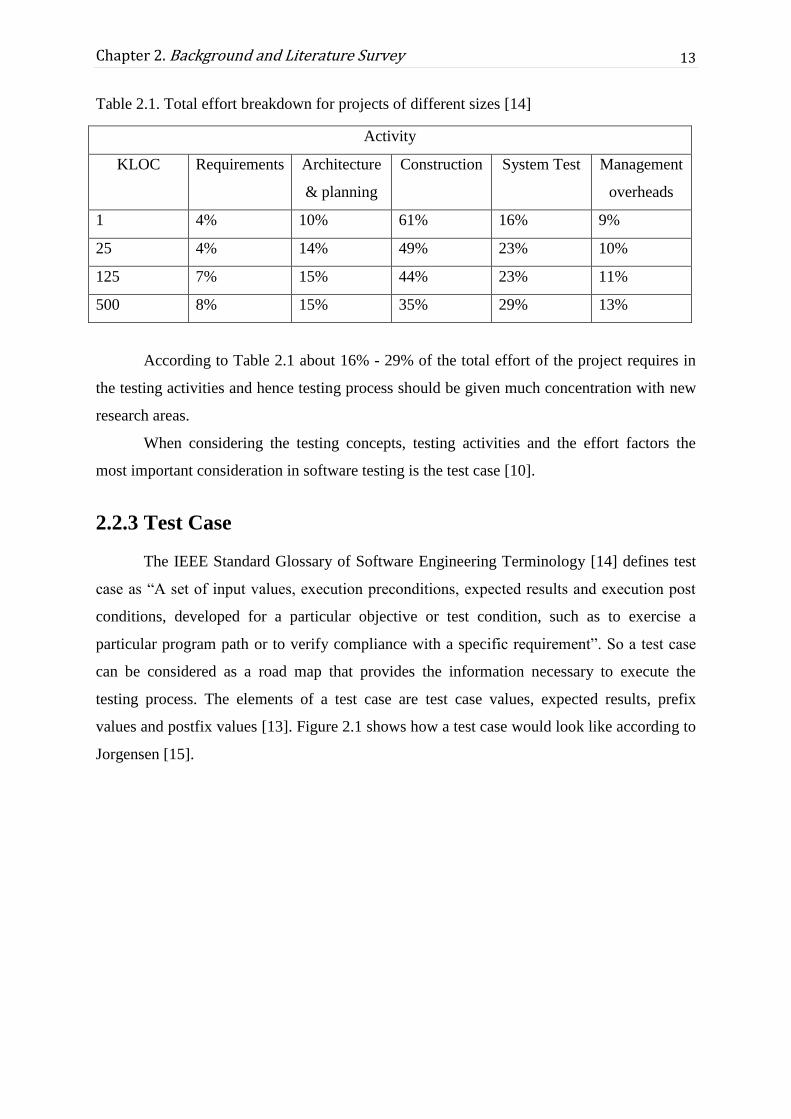
Table 2.1. Total effort breakdown for projects of different sizes [14]
Activity
KLOC Requirements Architecture
& planning
Construction System Test Management
overheads
1 4% 10% 61% 16% 9%
25 4% 14% 49% 23% 10%
125 7% 15% 44% 23% 11%
500 8% 15% 35% 29% 13%
According to Table 2.1 about 16% - 29% of the total effort of the project requires in
the testing activities and hence testing process should be given much concentration with new
research areas.
When considering the testing concepts, testing activities and the effort factors the
most important consideration in software testing is the test case [10].
2.2.3 Test Case
The IEEE Standard Glossary of Software Engineering Terminology [14] defines test
case as “A set of input values, execution preconditions, expected results and execution post
conditions, developed for a particular objective or test condition, such as to exercise a
particular program path or to verify compliance with a specific requirement”. So a test case
can be considered as a road map that provides the information necessary to execute the
testing process. The elements of a test case are test case values, expected results, prefix
values and postfix values [13]. Figure 2.1 shows how a test case would look like according to
Jorgensen [15].

14
Chapter 2. Background and Literature Survey
Figure 2.1. Typical test case information adopted [15]
As Figured under the motivation topic in the current industry the test cases are written based
on user requirements in natural language. In the agile software development it follows an
iterative approach to develop products incrementally with keeping the customer involved
from the beginning until to the end of the product. This methodology helps with the frequent
changes in requirements. Agile approach breaks down larger functionality into smaller pieces
called user stories and they are delivered within short two week cycles.
2.2.4 User story
As mentioned in previous Section 2.2.3, larger user requirements are broken down
into smaller pieces in Agile methodology because larger requirements capture high-level
behaviour and so they can be too large to complete in a single iteration. Therefore they are
broken down into smaller sets called user stories. In Agile approach, the user stories have lot
of advantages [16]. Some of them are it replaces time-consuming documentation and
encourage face-to-face communication between developers and business owners which
would lead to better understanding of requirements while decrease in misunderstanding.
Solis and Wang [17] discuss a template (shown in Figure 2.2) for a user story to
extract the information about the requirement that is needed for a particular user role.

15
Chapter 2. Background and Literature Survey
Figure 2.2. Template for a user story
According to the above studies, it shows that user stories and test cases have been
played an important role in the Agile environment. For further evaluation a survey was done
to do a background study on the Sri Lankan software development Industry.
2.3 Software Development Industry in Sri Lanka
Following details were able to discover by concerning 26 Software companies in Sri
Lanka. Through the study that have been done, 88.5% companies are following Agile
development as the software development methodology among 26 companies 57.7%
companies write user stories. The percentage of the companies who are not using design
diagrams are about 15.4% and 42.3% of the companies use design diagrams occasionally,
depending on the software product. The rest 42.3% frequently use design diagrams.
According to the survey the test design phase is a manual process in all those companies.
61.5% of companies are doing the test design in the testing phase of the software and only
34.6% is designing test cases at the requirement gathering phase. But survey also shows that
doing the test design in testing phase has been leaded to conflicts between test cases written
at the testing phase and the requirements written at requirement gathering phase. 77% of
companies have experienced the conflicts in software requirement and designed test cases.
The results relevant to this survey are shown in Appendix C.
According to the all above background analysis, it is possible to say that in the current
software industry the Agile practises are being followed and they are writing requirements in
the form of user stories while going along with a most suitable and common template to write
user stories. This study so far illustrated that software requirements in natural language
establish basis for development of quality software through generating proper and valid test
cases. According to the analysis details, currently test cases are generated manually and it is
better if writing test cases are based on the requirements to get rid of the conflicts that can
occur. Since test cases are written manually, automation of test case generation requires more
consideration.

16
Chapter 2. Background and Literature Survey
2.4 Automated test case generation
According to Nasser and Weichang (2010) in automated test case generation, test
cases are automatically generated based on a software artifact. These software artifacts can be
requirements, design diagrams (model based) or source code [18]. Rane (2017) has observed
that test case generation follows one of the above mentioned techniques.
2.4.1 Requirement based test case generation
The requirements are the fundamental inputs to the system and therefore test cases
need to be originated from the requirements and then the functionality of the system being
evaluated with the expected outcome. Majority of these software project requirements have
written in Natural Language [19]. According to Tahat and Vaysburg, requirements base
techniques interpret the required behaviour of the system which can be used as footing for
creation of functional test cases [20]. They concluded this as the key advantage of
requirement base technique.
Dwarakanath and Sengupta introduced a tool called “Litmus” to generate test cases
from a functional requirement document [21]. According to the study, generating test cases
from natural language requirements form an intimidating challenge because requirements do
not follow a predefined structure. Dwarakanath and Sengupta forced to not allow constraints
on the structure of the requirement sentence. The tool generates one or more test cases
through a six-step process.
Figure 2.3. Schematic of the Litmus Tool [21]

17
Chapter 2. Background and Literature Survey
Figure 2.3 illustrates the sequential process of Litmus that generates test cases from
the requirements document. Link Parser grammar with natural language processing
techniques has been used to implement the tool.
With the NLP techniques they have used, the automatically identified entities are
presented to the user for validation and this user verification helps increase the accuracy of
Litmus. Also Litmus has the capability of identifying Test Cases that were missed by the
human analysts. However, there are some scenarios where Litmus fails to generate accurate
Test Cases. In their methodology to generate Test Intents has been worked well in most
cases, however, in a few instances, the Test Intents seem incomplete and not understandable
due to the NLP boundaries that have been used.
2.4.2 Model based test case generation
Test cases are derived from the model of the system and according to the Neto and
Subrahmanyan model-based testing classified as requirements described in UML diagrams,
requirements described in Non-UML diagrams, Information from internal software structure
(architecture, components, and interfaces) described in UML and Non-UML diagrams [22].
According to them reusing or extracting a test model from the behavioural software models
improves the productivity of test team and software product quality.
Unified Modelling Language (UML) was developed and introduced by Object
Management Group (2003) to provide visualization of the behaviour and interaction of
system objects [2]. With the advantage of maintaining the consistency between design and
specification through UML diagrams encouraged much research on using UML in software
testing [23]. The dynamic UML diagrams consist of Use Case Diagram, Activity Diagram
and State diagram [4]. Noraida, Rosziati and Noraini (2007) have introduced automatic test
case generation from Use-Case Diagram [23]. According to Noraida, Rosziati and Noraini, at
first system’s requirements are transformed into a UML Use case diagram. Second, the test
cases will be automatically generated according to the respective use cases. Use cases are
developed based on the user perspective and which represent the functional requirement of
the system. If the requirements are gathered correctly, good use case diagram can be
composed. The suggested tool (GenTCase) by Noraida, Rosziati and Noraini generate test
cases once the use case diagram has been finalized.
Chevalley and Pascale have introduced a mechanism for an automated generation of
statistical test cases from UML state diagrams [24]. According to Chevalley and Pascale the

18
Chapter 2. Background and Literature Survey
techniques of software development have been evolved with object-oriented technology.
Therefore high-quality object-oriented software requires relevant testing to ensure that
software meets its requirement specification. The state diagram, which widely used to
represent dynamic behaviour of object, has used to generate test inputs. Moreover, for the
generation of test cases include both the input values and the expected values. In this case the
testing criterion used to mentor selection of input values of test cases is the coverage of the
transitions of the UML state diagrams. Then the generic algorithm was applied for random
generation of input values which produce sequences of test cases. Chevalley and Pascale
have mentioned that this approach represents a challenge for the testing of complex systems.
In 2001 Wang and Yuan introduced a method for generating test cases from UML
Activity Diagram [25]. They examined that test cases are usually generated from the
requirement or the code. However, according to the approach, test cases are generated from
UML activity diagram using the grey-box method. The mentioned that activity diagram is
related to the design phase of software development but using this methodology where the
design is reused to avoid the cost of test model creation. Activity diagrams have used to
model the workflow of the business requirement or complex behaviour of an operation. In
here Wang and Yuan examined that the design specifications are the intermediate artifact
between software requirement specification and final source code. Within that basis, Wang
and Yuan introduced the grey-box method to generate test cases which combined both white
box method [15] and black box method [26] in testing.
2.4.3 Source code based test case generation
In 2001 Fraser and Arcuri introduced a tool called “EvoSuite” for automatic test suite
generation for object oriented software [27]. It generates test cases with assertions for java
classes. The tool applied a novel hybrid approach that generates and optimizes whole test
suites to complete the coverage of test suites. This approach directly bound with
implementation phase. It requires Java byte code of the class under test and its dependencies
to generate test cases. It is observed that this tool is only supported with Java based software
and current software industry use many programming languages for software products. Also
they mentioned that the test case generation lot depend on the flow of implementation and
which lead to some missing of crucial path of find defects.
According to the research review done by Shivani Kaushik [28], source code based
technique has identified as a way of test case generation. It shows that source code based
techniques are based on the control flow information where control flow information has

19
Chapter 2. Background and Literature Survey
been used to point out a set of path to be covered and generated test cases for these paths.
It has identified some researchers who have done researches on this area during the years
1995 to 2008 and they have shown that the source code based techniques have given fewer
concentrations within that period of time.
Model-Based approaches where requirements are transformed from natural
language into computational models using Unified Modelling Language (UML) can be
lead to misunderstandings because of strict notations and principles [6]. In the current
software industry, the development methodologies have been changed due to unstable
requirements. Such new methodologies like Agile has given much concern on the
requirement based approaches rather than model-based approaches and source code based
approaches while concerning them with customer perspectives. Therefore requirements
written in natural language have gained the interest over others.
2.5 Entity extraction using Natural Language Processing
Natural Language Processing (NLP) techniques play an important role within the test
case generation process as shown in Section 2.4.1. Existing NLP techniques such as POS
Tagging, Dependency Parsing and Lemmatization can be used for entity extraction. This
section discusses the performance of Stanford CoreNLP, OpenNLP and Linked Parser
toolkits with respect to some algorithms which could be used for identification of POS tags,
lemma and dependencies while entity extraction in a triple form.
2.5.1 Stanford CoreNLP
Stanford CoreNLP is an open source Java-based suite of natural language processing
tools, initially developed in 2006 by the Stanford Natural Language Processing (NLP) Group
by Dan Klein and Christopher D [29]. This tool supports with various functions like
tokenizer, sentence splitter, POS tagger and dependency parser with analyzing sentiments to
provide syntactic analysis of a sentence. A natural language parser analyzes the grammatical
structure of sentences using probabilistic knowledge of the language. Probabilistic parsers
produce the most likely analysis of sentences and perform better than statistical parsers [30].
The Stanford NLP parser implements a probabilistic natural language parser based on
Probabilistic Context-Free Grammars (PCFG) and outputs Universal Dependencies and
Stanford Dependencies. The idea of grammatical structure consists of words linked by binary
asymmetrical relations called dependency is the underlying assumption of dependency

20
Chapter 2. Background and Literature Survey
parsing. These dependencies represent the relationship between the words of a sentence and
help in extracting relevant information from a complex sentence.
• Treebank
A treebank is a set of words represented in a tree form annotated with syntactic information.
Treebanks perform annotation based on the phrase structure of a sentence and the
dependencies between words where phrase tags are assigned to a group of co-located words
in a sentence which is similar to the POS tags. The Stanford Parser uses the Penn Treebank
for annotating the sentences with parts-of-speech tag sets. The Penn Treebank is a human-
annotated collection of 4.5 million words [31] which groups elements using phrase tags and
POS tags in a phrase tree structure.
• Stanford Dependency Representation
There are two types of dependency representations and they are Stanford dependency and
Universal dependency. The Stanford typed dependencies representation [32] extracts textual
relations based on the grammatical structure of a sentence. Stanford parser provides four
variations of typed dependency representations and they are basic, collapsed, propagation and
collapsed tree. The main difference between the typed dependencies is the manner of
representation which is in a tree form, or in a cyclic graph form. In the Stanford CoreNLP,
Universal dependencies are the default representation for extracting grammatical relations
since version 3.5.2. The new Universal Dependencies created in 2014 is a single framework
designed to add or improve the defined syntactic relations to better accommodate different
grammatical structures in various languages [33]. The current version of Stanford typed
dependencies contains 50 grammatical relations which make use of the Penn Treebank POS
and phrase tags [34]. The dependencies are in the form of binary relations where a
grammatical relation holds between a governor which is also known as a regent or a head and
a dependent. The Stanford typed dependencies are a better representation which provides a
simple description of the grammatical relationships in a sentence that can comfortably be
understood and productively used by people without linguistic expertise who want to extract
textual relations.

21
Chapter 2. Background and Literature Survey
2.5.2 Triplet Extraction
From a given sentence to extract the entities and their relations that sentence needs to
be applied to some NLP techniques. A triplet in an English sentence can be defined as a
relation between subject and object and the relation being the predicate. In the triplet
extraction it is trying to extract sets in the form of {subject, predicate, object} out of
sentences. There is much research and implementation has been carried out in the area of
extracting triplets from sentences and they have been used machine learning technique and
Treebank Parser as two main techniques.
1. Machine Learning Technique
A machine learning approach has been used [35] to extract subject-predicate-object
triples from English sentences. They have used an SVM to train a model on human annotated
triplets, and the features are computed from three parsers. The sentence is tokenized and after
that stop words and punctuation are removed among tokens. Then by taking a list of
important tokens in the sentence, all possible ordered combinations of three tokens from the
list are taken. The resulted combinations are the triplet candidates. From there onwards the
problem is seen as a binary classification problem where the triplet candidates must be
classified as positive or as negative. The SVM model assigns a positive score to those
candidates which should be extracted as triplets, and a negative score to the others and the
higher positive score words formed the resulting triplet. In practice in this classification
described here there are many false positives, and therefore it does not work to take them all
as the resulting triplets and instead it only takes the top few from the descending ordered list
of triplet candidates.
2. Tree Bank Parser
This approach is to extract subject-predicate-object triples using available syntactic
parsers that generate parse trees with parser dependent techniques. Two different algorithms
could be founded that uses treebank parser and they are ‘Triplet extraction algorithm for
Treebank parsers’ and ‘Multi-Liaison algorithm.
• Triplet Extraction Algorithm for Treebank Parsers
Extraction of triplets in a sentence from the parse trees using different parser
dependent techniques that used in publicly available parsers have been presented by Delia

22
Chapter 2. Background and Literature Survey
Rusu, Lorand Dali, Blaž Fortuna, Marko Grobelnik, Dunja Mladenić [29]. The approach has
introduced an algorithm for extracting triplets from a treebank output in the form of subject -
predicate - object. In this algorithm, a sentence is represented by the parser as a tree having a
Noun Phrase (NP), a Verbal Phrase (VP) and the ‘full stop’ as its three children. The root of
the tree will be ‘S’. To find the subject of the sentence it searches in the NP sub-tree and by
performing Breadth First Search, selects the first descendant of NP which is a noun. In
determining the predicate of the sentence, the search will be performed in the VP sub-tree and
selects the deepest verb descendent of the verb phrase as the predicate. According to their
algorithm, the objects of the sentence can be retrieved from all siblings of the VP sub-tree
containing the predicate.
Performance
The extracted triplets are in the of form subject - predicate - object and to measure the
performance of the above algorithm they have used different publicly available parsers.
Using Stanford Parser, the above algorithm was implemented in Java and it has parsed
the sentences in 178.1 seconds with generating 118 triples. Using OpenNLP which is a
collection of projects for natural language processing, the above algorithm was implemented
in C# and has parsed the sentences in 29.95 seconds with generating 168 triples. Triplet
extraction using Link Grammar Parser, the application was written in C++ and generates a
linkage after parsing a sentence using the Link Grammar. It parsed the sentences in 271
seconds with generating 110 triples.
Litmus tool which discussed in above Section 2.4.1 also uses Link Grammar parser
and the aim is to extract entities by picking up all entities from the requirement document and
the every requirement sentence is parsed by Link Grammar.
• The Multi-Liaison Algorithm
This is an approach for extracting multiple connections or links between subject and
object from natural language input, which can have one or more than one subject, predicate
and object [34]. It has used the Stanford parser dependencies to extract the information from
a given sentence while the output displays which subject is related to which object and the
connecting predicate. The Multi-Liaison Algorithm output can be beneficial for text mining
applications where a variety of sentences are to be mined. The algorithm name uses ‘Liaison’
since the relationship and association between the subjects and predicates are being displayed

23
Chapter 2. Background and Literature Survey
by this. The output would be used for natural language processing, information retrieval,
information extraction and also text mining applications.
Performance
The application was written in Java using Stanford parser and it parsed a single
sentence of 12 words in 8.35 seconds.
Treebank parsers techniques are likely to be used rather than machine learning
techniques applied with NLP. Both the algorithms discussed above using treebank parsers
have the intention of finding entities as in a triplet form where they concerned on extracting
more than one entity per category. In the first algorithm mentioned has used a tree to present
the sentence and in the other algorithm it has used dependency parser which concerns
relations among the words in the sentence. According to the performance analyzed by those
researchers, have shown that the applications for extracting triplets written using OpenNLP in
C# have given better performances compared to Stanford parsers and Link Grammar Parser.
However, at the same time it shows that the Stanford Parser in Stanford CoreNlp toolkit is a
widely used technique as it can be used with Java language with many of the open source the
implementations.
According to the stated details above, it has identified that requirement needs to be
given a higher consideration with the test case generation. Therefore a good representation of
domain knowledge of requirement can be given much attention to making a better use of the
requirements.
2.6 Use of Ontology
Ontology can be identified as a formal explicit description of concepts in a domain of
discourse [36]. Properties of each concept explain different characteristics and attributes of
the concepts. Not only that Ontology act together with a set of individual instances of classes
constitutes a knowledge base. According to the Natalya and Deborah studies, Ontology
defines a common vocabulary for the researchers who work and want to share information in
a particular domain. Therefore Ontology provides a shared understanding of the structure of
information, enable reusability of domain knowledge, make explicit assumptions for the
domain, and analysis of domain knowledge.
24
Chapter 2. Background and Literature Survey
According to the Mansoor Ontology-based system have emerged in many application
domains namely E-commerce, Medical, Chemistry and the foremost Knowledge
Management System (KMS) [37]. There are three kinds of Knowledge management
Ontologies ((Gómez-Pérez, Fernández-López, & Corcho, 2004 [38])
1. Information Ontology: Contains generic concepts and attributes
2. Domain Ontology: Is used to describe the contents
3. Enterprise Ontology: Is used for the organization description.
In 2007 Breitman stated that Ontologies should provide classes which various preset
concepts in the domain, relationships among these concepts and properties to possess the
concept’s attributes [39].
2.6.1 Software Engineering Ontologies
Wongthongtham, Chang and Dillon have introduced a new approach to software
engineering which organizes software engineering concepts, ideas and knowledge concerning
the software development methodologies, tools and techniques into Ontologies [6]. Then use
Ontologies as a foundation for classifying the concepts in knowledge sharing and
communication. The necessity of a common communication mechanism in software
development industry is vital because the complexity of the industry is getting increased. The
studies described the features of software engineering Ontologies and how software
engineering Ontologies can be developed. According to the studies, researchers proposed two
Ontologies for software engineering.
1. Generic Ontology
This Ontology is a set of software engineering terms which include the vocabulary,
the semantic interconnections and some simple rules of inference and underlying logic for
software development. In general contents of software engineering are elucidated with a
concept or relationship from the generic Ontology.
2. Application specific Ontology
This Ontology provides an explicit specification of software engineering concerning
the particular development project. Application specific Ontology ensures consistent
understanding among project members, software agents according to the project agreement.

25
Chapter 2. Background and Literature Survey
Figure 2.4. An overview of generic Ontology and application-specific Ontology of software
engineering [6]
Figure 2.4 illustrates an overview of generic Ontology and application specific Ontology with
relationship between internal components and their attributes.
2.6.2 Ontology representation and implementation
According to the definition of W3C Vocabularies are the basic building blocks for
inference techniques on the Semantic Web [40]. The W3C said that, there is no clear division
between “vocabularies” and “Ontologies” concerning the domain of existence. The word
“Ontology” has been used for more complex, and possibly quite a formal collection of terms.
Mansoor mentioned that semantic web has a proficiently defined combined with its rules of
reasoning for data representation [37]. Ontology Web Language (OWL) is used to describing
the meaning of the resources and supporting its reasoning in the semantic web. According to
Antoniou and Harmelan (2008) semantic web technology lie on technologies layers which are
built on each other [41]. The web data provided by layers is linked and connected to its

26
Chapter 2. Background and Literature Survey
resources by the Uniform Resource Identifiers (URIs). Table 2.2 depicts the description of
semantic web technology layers.
Table 2.2. Semantic Web technology layers description [37]
Layer Definition
URI The Uniform Resource Identifier (URI) is a string of characters for identifying an
abstract or physical object or resource. URI is particularly suitable for referring to
objects on the web.
XML The Extensible Markup Language (XML) is a language for users to mark up
content using tags to structure a web document. XML is particularly suitable for
sending documents across the Web.
RDF The Resource Description Framework (RDF) is a language that has XML-base
syntax for representing information about resources in the web. RDF is
particularly suitable for representing metadata about web sources.
RDF(S) The Resource Description Framework Schema RDF(S) is a language to create
vocabulary for describing the RDF resources such as classes, subclasses, and
properties. RDF(S) is particularly suitable for providing modelling for the Web
objects.
RIF The Rule Interchange Format (RIF) is a language (under process) to give the
basic rules for checking.
OWL The Web Ontology Language (OWL) is another extension of RDF(S) for
describing and sharing Ontologies (more info about Ontology on chapter 3).
OWL is defined as three sublanguages: OWL Full, OWL DL, and OWL Lite.
SPARQL The Protocol and RDF Query Language (SPARQL) is a special query language
for express queries across diverse data sources. SPARQL is particularly suitable
as the results of query can be result set or RDF graph.
The representation and implementation of an Ontology are crucial whether it is generic
Ontology or application specific Ontology. According to the Wongthongtham, Chang and
Dillon study there are many languages to represent an Ontology such as Knowledge
Interchange Format (KIF), Ontology Exchange Language (XOL), Ontology Markup
Language (OML), Ontology Inference Layer (OIL, DAML+OIL) and Web Ontology
Language (OWL) [6]. Researchers used OWL because it has become the official W3C
standard since 2004 which was released by the World Wide Web Consortium [42]. OWL

27
Chapter 2. Background and Literature Survey
Ontology consists of individuals, properties and classes and describes the relationships for the
domain. For the implementation of Ontology researchers used Protégé OWL tool.
According to the Dermeval and Vilela OWL Ontologies are mostly serialized with
RDF or XML representation which is also a part of W3C technologies [43]. It is a triple
format which models the knowledge information using triples. This triple is in the form of
subject, predicate and object expressions. Therefore information in RDF format can be
queried using SPARQL [44] query language. When compared with SQL, additionally
SPARQL used Semantic Web Rule Language (SWRL) which extends the set of OWL
axioms.
2.6.3 Ontology Languages
In the study done by Mansoor [37], mentioned the need of representing and
exchanging data on the internet. Therefore some languages have created to support Ontology
in the context of the semantic web. Figure 2.6 depicts the classification of Ontology building
languages and Table 2.3 illustrates the summary of the most famous Ontology languages.
Figure 2.5. Classification of Ontology building languages [45]

28
Chapter 2. Background and Literature Survey
Table 2.3. List of Ontology Languages [37]
Name of Ontology
Languages
Developed
On
Developed By Purpose
Ontology Exchange
Language (XOL)
XML (Karp, Chaudhri,
& Thomere,
1999)
To provide a format for
exchanging Ontology definitions
among a heterogeneous set of
software systems.
Simple HTML
Ontology Extension
(SHOE)
HTML (Luke S, 2000) To improve search mechanisms
on the Web by collecting
meaningful information about
Web pages and documents.
Ontology Inference
Layer (OIL) + DARPA
Agent Markup
Language (DAML)
RDF(S) (Horrocks, 2002) To allow semantic markup of
Web resources.
Web Ontology
Language (OWL)
XML &
RDF(S)
(McGuinness &
Van Harmelen,
2004)
To publish and share Ontologies
in the Web
According to the research study identified that, for the context of semantic web use the XML
based language such as RDF and OWL are effective. The main advantages of that selection
are comfortable reading and managing with support from the different groups and
communities. Also, provide availability if more tools to update and develop the Ontology.
2.6.4 Ontology building tools
Some tools have been introduced to help the users to develop their Ontology tasks.
According to Gomez (2004), these tools target to enable the process development and
reusability of Ontologies [38]. Perez had classified Ontology tools as development tools,
evaluation tools, merge and alignment tools, Ontology-based annotation tools, querying tools,
inference engines and learning tools. Table 2.4 depicts the summary of tools that relevant to
facilitate the development of Ontologies according to the study of Su and Ilebrekke in 2006
[45].

29
Chapter 2. Background and Literature Survey
Table 2.4. List of Ontology Building Tools
Ontology
Tool
Developed by Special Purposes
Ontolingua Farquhar, Fikes, & Rice - 1997
[46]
Development of Ontologies in s shared
environment among distributed teams
WebOnto Domingue - 1998 [47] For corporate browsing, creating and
modifying Ontologies
Prot´eg´e-
2000
Noy, Fergerson, & Musen - 2000
[48]
For grapghical software development
platforms
OilEd Bechhofer, Horrocks, Goble, &
Stevens - 2001 [49]
To automatic concept classification
OntoEdit Sure et al. - 2002 [50] To support the plug-in architecture
WebODE Arpírez, Corcho, Fernández-López,
& Gómez-Pérez - 2003 [51]
To ease the access services
For the study of suggested solution, Prot´eg´e-2000 has been selected as Ontology building
tool because it is an open source standalone application. Also, the application is written in
Java and supports as OWL editor and reasoner. Moreover according to current development
environment graphical visualization is very vital. Prot´eg´e-2000 provides that feature by
visualizing classes and properties of Ontology in different colours. Therefore developers can
easily do their works [37].
For deriving implicit knowledge from a knowledge base that is written in a knowledge
representation language, Reasoning gets involved. Since Ontology being a knowledge base
representation, it needs to be applied with the reasoning to obtain implicit knowledge
represented in the knowledge base.
2.6.5 Apply reasoning on Ontology
Ontology is one of an interpretation of the semantic web. The reasoning is another
term that tightly coupled with Ontology. Reasoning in Ontologies and knowledge bases
provide explicitly deriving from facts which are not directly expressed in Ontology or
knowledge base. According to Ameen, Rahman and Ram (2014) semantic web use automated
tools and reasoners for supporting knowledge management with extracting new knowledge

30
Chapter 2. Background and Literature Survey
from existing knowledge and checking inconsistencies [52]. This paper depicts that Jena API
which is an open source semantic web framework for Java and it can be used to extract data
from and write to RDF graphs and OWl Ontologies.Also mentioned that SPARQL could be
used to query the RDF graph or OWL Ontologies. The reasoning of Jena works on the
Ontology to derive truth from the model. Additional facts such as transitive and reflective
properties can be derived using a range of reasoners provide by the Jena inference
subsystems. Another advantage of Jena Ontology API is, it is independent of Ontology
language.
In 2014 Glimm and Horrocks introduced another OWL reasoner called HermiT,
which supports all features of OWL 2 Ontology language including all data types and data
properties [53]. Apart from the standard reasoning tasks, HermiT also supports for SPARQL
querying and ensure efficient processing of real-world Ontologies. When comparing with
Jena and HermiT, Jena supports for all Ontology languages and HermiT concentrate on OWL
which can be taken as a drawback.
As stated so far Ontology has become a widely applicable area concerning to the
representation of domain knowledge where that knowledge can be reused within the domain.
Therefore analyzing the opportunities of Ontology-based approaches that have been used
with the generation of test cases so far can be taken as an important aspect.
2.6.6 Ontologies in test case generation
The primary objective of the project is to find the possibility of automatically generate
test cases based on an Ontology. Hence the usage of Ontology in test case generation plays a
vital role in this background analysis. Therefore identifying existing Ontologies for the
required domain, studying the features in Ontology such as relationship identification, rules,
and reasoning, and observations of already introduced solutions earn big attraction to prove
the suggested objective mentioned above.
According to the Nasser’s and Weichang’s test generation framework in 2010, used
Ontology approach to implement the solution [18].They used the behavioral model Ontology
to describes concepts related to the software artifact elements, the relationship between them
and their instances. Expert knowledge Ontology used and it extends the behavioral model
Ontology and knowledge is utilized by the coverage criteria rules for identification of test
objectives. It is observable that Ontology has the advantage of hold the knowledge
concerning the particular domain. Experts can be worked on particular knowledge Ontology

31
Chapter 2. Background and Literature Survey
and they can use reasoning on Ontologies to derive necessary outcomes. They concluded that
Ontologies should be developed for the software artifacts and to the required domain.
According to these, it can be seen that there is no such existing Ontology developed
for software requirement domain. There are some properly identified mechanisms with how
to develop an Ontology for a particular domain, but there are no any Ontology-based
proposed approaches that have been used practically so far.
Though there are no any Ontology-based approaches, there could have some other
mechanisms or similar solutions that have been proposed through various systems. To get the
details if there exist any such solutions this thesis analyses further about similar systems and
solutions.
2.7 Similar systems and solutions
Three similar systems that have been proposed to automatic test case generation have
been found.
As stated in Section 2.4.1 Litmus is a requirement based automatic test case
generation tool which identifies a requirement as a sentence that has a label (given for
traceability) in a requirement document and generates one or more Test Cases. This one Test
Case includes the Test Condition, the Test Sequence and the Expected Result. A “Test
Condition” is defined as the entry criterion for the Test Case or the particular condition which
is being tested. The ordered sequence of steps a tester would have to execute to perform the
test is called “Test Sequence”. Litmus uses a syntactic parser called Link Grammar parser to
parse the requirement sentence and has a set of pattern matching rules to check the testability,
identify Test Intents and generate Positive and Negative Test Cases in a systematic manner. If
the parser is unable to link the sentence, it is reported as a “failed case” and the analysis
moves to the next sentence. If the testable requirement is a compound or complex sentence, it
is simplified into a set of simple sentences. This simplification is made by identifying the
links from the LG parse that represent compound/complex sentences and handling them
appropriately. Generating of Test Intents is done according to predefined rules. For a
compound/complex sentence, the Test Case is generated for each simplified sentence and
merged according to the semantics of the conjunctions. Litmus has been implemented as a
plug-in into Microsoft Word and Excel using .NET. The implementation calls the LG parser
run-time (in C) as a managed code library from the .NET environment. Litmus was tested

32
Chapter 2. Background and Literature Survey
over actual requirement documents from various projects in the industry. The overall
accuracy of Litmus was seen at 77% and varied from a low of 56% to a high of 84%. But one
of the issues is Litmus is driven largely on the syntax of the sentence. Some lexical semantics
is inbuilt, for handling coordinating and subordinating conjunctions. Such semantics are
context and domain agnostic. Still Litmus is not popular among software companies since it
has been implemented as a plug-in into Microsoft Word and Excel using .NET.
Cucumber [54] is a command line, automatic test case generation tool which is for the
companies who follows a BDD approach. Though such companies follow BDD approach,
because of the Cucumber tool they have no intention of keeping user stories and rather they
keep requirements in a file called feature file. These files are written using keywords such as
“Given”, “Then”, “And” and etc. When the feature file is executed, a method is implemented
directly into a code level without the method body.
The usage of cucumber has limitation since it can be used by BDD driven companies
but most of the BDD driven companies tend to write user stories because of the customer
requirements. Also it is an additional effort and cost for creating feature files used in
Cucumber tool. Since the method body is not automatically generated, it has to be written by
a QA engineer. Therefore to use Cucumber QA team has to be aware of some programming.
J-pet is a code based, white box test-case generator (TCG) which can be used during
software development of Java applications within the Eclipse environment. jPET builds on
top of PET. PET is a research prototype which aims at automatically generating test cases
from Java bytecode programs by relying on the technique of partial evaluation. The system
receives as input a bytecode program and a set of optional parameters, including a description
of a coverage criterion; and yields as output a set of test cases which guarantee that the
selected coverage criterion is achieved and optionally, a test case generator.
jPET incorporates a test-case viewer to visualize the information computed in the test-
cases (including the objects and arrays involved). It can display the test-case trace, i.e., the
sequence of instructions that the test-case exercises. jPET can also parse method
preconditions written in JML [55]. This can be very useful for avoiding the generation of
uninteresting test-cases, as well as for focusing on (or finding) specific ones. jPET can be
used as this. Once a Java source file is opened, the user can select in the outline view of
Eclipse the methods for which he/she wants to generate test-cases. Once selected, clicking on
the jPET icon opens the preferences window of jPET which allows setting preferences. The
obtained test-cases are then shown in a tree-like structure organized in packages, classes and
methods in the jPET view.

33
Chapter 2. Background and Literature Survey
The test-case viewer basically consists of three modules. The output of PET has been
extended so that an XML file containing all the information of the obtained test-cases is
generated [55]. The Graph Manager, based on JGraph manages the graphical representations
based on the heap data structure. Each graphical representation is basically a graph that
encapsulates the heap, or part of it, and contains information about how it should be
displayed by the interface [55].
On top there have a Swing based interface that allows the programmer to interact with
the Graph Manager by creating, displaying and exploring their preferred representations of
the heap [55]. jPET symbolic execution engine works at the bytecode level, allows using it
for Java bytecode programs for which the source is not available. This could be very useful
from the point of view of reverse engineering.
But Jpet has some issues since it is a code level test case generation plugin written for
java.

34
Chapter 2. Background and Literature Survey
2.8 Summary
This background analysis has explored almost all the areas that could come up with
the test design phase in the software testing phase. Software testing is a main concern in order
to build up a better quality product and the test design phase within software testing phase has
a large impact on time, cost and effort factors. But both in theoretically as well as in
practically the test design phase is still a manual process where writing of test cases is needed
to be done by looking at the user requirements for the reason of removing conflicts that could
occur at other phases of testing.
There are 3 different approaches introduced for the automatic test case generation and
they are requirement based approach, model based approach and source code based approach.
Also when comparing these 3 approaches the requirement based approach has gain the
interest over others due to the Agile practises that follows in the current software industry.
Along with the Agile practises, user requirements are written in the form of user stories and
there is a typical common template that has been introduced for the writing of user stories.
As aforementioned, requirements written in natural language has gained attention
with generation of test cases which underlies the effectiveness and efficiency of the testing
process with respect to those factors mentioned. Natural Language Processing techniques are
concerned with requirements for the extraction of entities and relationships reside in the
given sentences. Multi-Liaison Algorithm has introduced a dependency parsing technique
which can be seen as a more useful mechanism with extracting entities since it considers on
how entities are related. Stanford CoreNLP toolkit has been used popularly compared to other
tools because of the capability of using it with open source Java implementation. In that
Stanford typed dependencies are a better representation which provides a simple description
of the grammatical relationships in a sentence.
Semantic web technology holds various promises for developing efficient conceptual
web data represented in a formalism approach and Ontology is one such approach where it
stands out as a promising technology for knowledge development and representation. There
are some conceptual level Ontology based approaches with test case generation but nothing
can be founded as a developed existing one. However this chapter stated that Ontology based
idea opens up many possibilities with knowledge representation and there is a high chance
that this technology can bring many benefits with the automation of test case generation.

35
Chapter 3
Methodology
3.1 Introduction
This chapter describes the proposed research approach for the Ontology based test
case generation methodology. It is introduced as a series of transformations from a user story
up to the generation of test suites in natural language. To be more precise this discussion goes
along with present software requirements as user stories, process user stories in English using
natural language processing, involvement of an Ontologist to software industry, an Ontology
based representation of software requirements, implementation of software requirement
Ontology, reasoning the Ontology for generate test cases and workflow for derive test suites
according to the user stories. The research approach has discussed along with the above
mentioned transformations and the methods of data collection by selecting a sample user
story which will process through the followed steps within the methodology up to derivation
of the output as test cases.
3.2 Method Overview
The method generates a test suite in 3 main phases. Figure 3.1 illustrates the phases of
test case generation framework with their inputs and outputs. Phase 1 extracts the set of
entities from user stories then phase 2 performed to find out test cases by applying reasoning
on Ontology, Ontology acted as the pre implemented inputs for this phase. In phase 3, a
completed test suite can be derived by doing modification and insertion on that automatically
derived test cases.
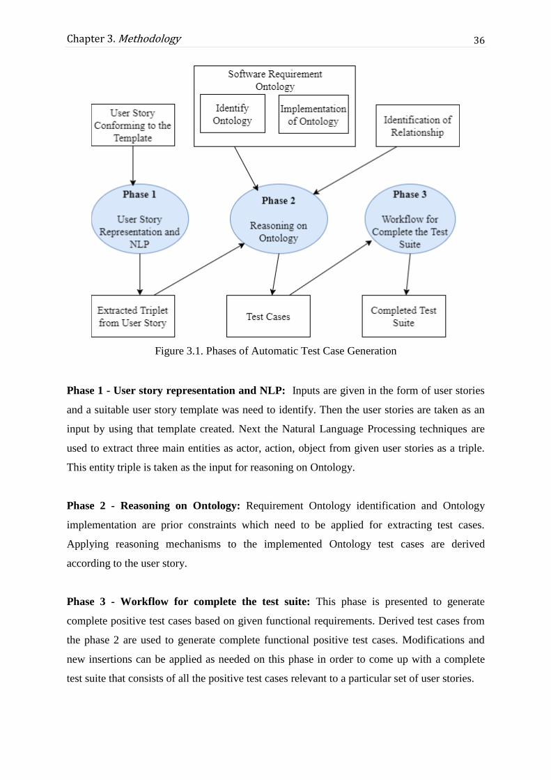
36
Chapter 3. Methodology
Figure 3.1. Phases of Automatic Test Case Generation
Phase 1 - User story representation and NLP: Inputs are given in the form of user stories
and a suitable user story template was need to identify. Then the user stories are taken as an
input by using that template created. Next the Natural Language Processing techniques are
used to extract three main entities as actor, action, object from given user stories as a triple.
This entity triple is taken as the input for reasoning on Ontology.
Phase 2 - Reasoning on Ontology: Requirement Ontology identification and Ontology
implementation are prior constraints which need to be applied for extracting test cases.
Applying reasoning mechanisms to the implemented Ontology test cases are derived
according to the user story.
Phase 3 - Workflow for complete the test suite: This phase is presented to generate
complete positive test cases based on given functional requirements. Derived test cases from
the phase 2 are used to generate complete functional positive test cases. Modifications and
new insertions can be applied as needed on this phase in order to come up with a complete
test suite that consists of all the positive test cases relevant to a particular set of user stories.

37
Chapter 3. Methodology
As identified in the chapter 2, since user requirement plays a vital role within test case
generation methods, in this proposed method also takes requirements as input in user story
user stories format. Representation of software requirement in the form of user stories was
taken into consideration with respect to Agile practises.
3.3 User stories as representation of software
requirements
Agile development has three terminologies for describe requirements in software as
epic, feature and user story. These terminologies are being used differently in different
development environment and it is based on how a developer defined them. Developer can
state there are only epics and user stories and there are no features because there are no sub
tasks to consider as features. Depending on which agile framework (scrum, kanban, or your
own unique flavour) is using, epics can be defined in different ways. For kanban, epics are
defined as swimlanes to segment different streams of work in requirements. If using scrum,
epics help to label the work in the sprints where sprints are some set of tasks that delivered
within short period of time.
An epic can be divided into several subtasks which are called features. A feature is a
distinct element of functionality which can provide capabilities to the business. It generally
takes many iterations to deliver a feature. A user story is defined as a subtask of a feature
where one feature can contain several user stories. The following Figure 3.2 shows this
intention.
Figure 3.2. Brake Down of Epic
38
Chapter 3. Methodology
As discussed in Section 2.3 in Background chapter, user story is a requirement
representation method which is most favoured in the software industry. Most of the
companies are using a same template as shown in Figure 2.2. This proposed methodology
also used this user story template that comes under epics as the input.
The following scenario is an example for an epic and user stories.
Epic: Group Management
Sub tasks within this epic are as follows:
Add a new Group
Update a Group
Delete a Group
View Users who belong to a Group
View Groups of a User
List Groups
Search for existing Groups
User stories for each of above subtasks will be written and user story for the sub task “Add a
new group” will be written as follow.
A Subtask of epic: Add a new Group:
User story: “As a User Admin, I want to add a new user group to the system, so that I can add
users to that group and manage them easily.”
With studying and suggesting a way to write user stories, then the next consideration
was given to the Ontology module development with the concept of introducing of a new role
as an Ontologist into the current software industry.

39
Chapter 3. Methodology
3.4 Involvement of an Ontologist in the software industry
An Ontologist is an expert in study of Ontology. The mission of the Ontologist is to
create knowledge graphs and linked metadata schemes for a required domain. An Ontologist
should have an ability to develop and implement Ontologies for the domain, integrate
Ontology requirements across components, identify mapping approaches for conversion
between different Ontologies, maintain knowledge related to Ontology tools, metrics, and
process improvements, validate and review requests for Ontology changes. Apart from above
major requirement Ontologist should be familiar with lexical semantics, NLP and semantic
analysis.
According to the capabilities of an Ontologist as mentioned above, software industry
can be effectively improved with the involvement of an Ontologist. The application of the
role of an Ontologist in the agile software development methodology is depicted through this
research project. The aforementioned issue regarding the inconsistencies between the user
stories and test case can be reduced with the use of an Ontologist. The proposed solution has
identified that the role of an Ontologist can be used in the requirement gathering phase in
order to map the requirements of the product owner with the proposed Ontology model. The
proposed Ontology model is discussed in Section 3.5. The knowledge base of the proposed
solution can be evolved with the contribution of the Ontologist.
3.5 Software Requirement Ontology
The software requirement Ontology is the Ontological representation of software
requirements. This Ontology model is based on software requirements presented by the
product owners and the model will be developed by an Ontologist according to the
requirements domain. In this proposed methodology, a generic Ontology is to be developed
apart from an application specific Ontology since the intention is to make reuse of the
developed Ontology within the overall testing process. The need of an Ontologist was
discussed in the Section 3.4 where Ontologist need to be a member of clients’ meeting where
requirements are discussed between client or product owner and Business Analysts in the
company. While BA person scratched down the requirements, Ontologist can get a better idea
about the requirement domain by participating in these discussions. By analysing the
requirements Ontologist can identify what are the main entities that are needed to inject into
the developed Ontology in a case of a new entity representation.

40
Chapter 3. Methodology
Developing a complete full Ontology from the scratch for the entire software
requirement domain is a harder approach and therefore this proposed framework would be
given as a generic solution for the ‘Group Management’ epic, a frequently used epic in most
of the software systems. Since Ontology provides a structured means of storing information
and linked data, the usage of Ontology for test case generation can be well justified using this
epic scenario. System objects, actions and properties are mapped to Web Ontology Language
(OWL) as classes and properties.
3.5.1 Class hierarchy of the Ontology
The class hierarchy of the developed Ontology module in this proposed methodology
is shown in the following Figure 3.3.
Figure 3.3. Ontology Class Hierarchy
Anything entered into the Ontology is called as a concept. Class concept is further
divided into subclasses as actor, action, object and condition. After studying the sample user
stories and their test cases, it could be identified that most of the test cases are based on the
functionality and the object where functionality is directly addressing in the user story.
Therefore the actor, action and the object were identified as the classes of the Ontology
model concept. Actor in a software engineering domain is the one who is performing or
having the authority for a particular functionality of the system. The actions described the
system functionalities.
The following Table 3.1 shows the definitions of the classes which have been used in
the Ontology model and its’ description.

41
Chapter 3. Methodology
Table 3.1. Classes of Defined Ontology
Class Description
actor An actor represents the subject, the doer who is doing the action of a
sentence.
action An action represents system functionalities, which system users (actors)
can perform inside its’ sub classes.
objectChange An objectChange action is a kind of an action where the direct object of
that action is changed once the action is performed.
objectNotChange An objectNotChange action is a kind of action where the direct object of
that action does not changed once the action is performed.
object An object represents the object of a sentence on which the action is
directly performed.
condition A condition represents situations as preconditions that needs to be
checked before doing an action.
Class action is divided into two subclasses as objectNotChange and objectChange as shown
above. Section 3.5.4 is discussed about this further.
Every class has its instances called as individuals. The following Figure 3.4 shows some
instances for the class ‘action’.
Figure 3.4. Instances of Class Action
Each of the individuals defined in the Ontology can have properties and they can be
categorized as object properties and data properties.

42
Chapter 3. Methodology
3.5.2 Object Properties of the Ontology
The relationship between two classes can be defined as Object property with respect
to those two instances. Relationship between two instances in the same class also defined as
object properties. The following Figure 3.5 shows some examples for those object properties.
Figure 3.5. Object Properties of Defined Ontology
Following Table 3.2 shows a description of object properties in the proposed Ontology.
Table 3.2. Object Properties of Defined Ontology
Object
Property
Domain Range Description
hasAction actor action The relationship between classes actor and action is
defined as hasAction.
hasObject action object The relationship between classes action and object is
defined as hasObject.
hasSimilarword action action A relationship between two instances of class action.
hasDependency action action A relationship between two instances of class action.
The object properties hasSimilarword and hasDependency are defined for handle special cases. User
stories are written by different users, therefore they might use different words to describe the
same things with relevant to their knowledge. To handle this critical condition, object
property hasSimilarword has been introduced with the intention of reducing the redundancy.
Properties have defined into one instance and those properties are accessing through
hasSimilarword object property.

43
Chapter 3. Methodology
There can be implicit user stories which are indirectly depend on another user story.
As an example, when a user performs action ‘update’, it indirectly depend on the action
‘view’ and therefore action ‘update’ has object property hasDependency on the action ‘view’.
To handle those kinds of situations, the object property hasDependency was introduced.
3.5.3 Data properties of the Ontology
Properties of an instance are defined as data properties. The following Figure 3.6
shows some examples for the data properties and Table 3.3 describes some of the data
properties which have been defined in the Ontology.
Figure 3.6. Data Properties of Defined Ontology
Table 3.3. Data Properties of Defined Ontology
Data property Domain Description
validName actor, object This property belongs to both actor and
object since when creating an actor or an
object, the name should be valid.
lengthy_name actor, object lengthy_name is a sub data property of
valid name. An instance of a given
domains can be created with a lengthy
name.
lengthy_name actor, object lengthy_name is a sub data property of
valid name. An instance of a given
domains can be created with a lengthy
name.

44
Chapter 3. Methodology
name_with_special_characters actor, object This is a sub property of property
validName. An instance of a given
domains can be created with special
characters such as ‘@’,’$’.
non_empty_name actor, object non_empty_name data property has two
domains actor and object, since when an
instance is created its’ name is
mandatory.
non_existing_name actor, object When an instance is create its’ name
should not be an already existing name,
therefore non_existing_name has defined
as a data property.
ID actor, object Both actor and object has data property
ID which is a unique number.
valid_Email actor An instance of actor has a valid_Email.
view objectNotChange Action view is belonged to sub property
objectNotChange and has sub data
properties view_all_objects and
view_top_N_view of objects.
view_all_objects objectNotChange Action view has data property
view_all_objects. When a user needs to
perform action view, it can be to view all
instances of particular class.
view_top_N_view of objects objectNotChange This is sub data property of data property
view. When a user needs to perform
action view, it can be to view only top N
number of instances of particular class.
delete objectNotChange This property is defined for action delete,
having sub data properties,
delete_after_the_approval and
send_confirmation_message.
delete_after_the_approval objectNotChange This sub data property is defined to give
the knowledge of action delete to the
Ontology. Before performing action
delete, an approval must be taken.
send_confirmation_message objectNotChange After deleting a particular instance a
confirmation message need to be
send.For that, the sub data property
send_confirmation_message has been
introduced.
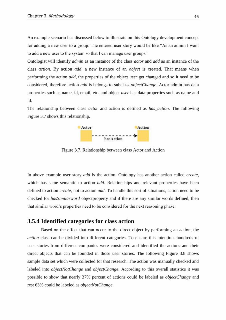
45
Chapter 3. Methodology
An example scenario has discussed below to illustrate on this Ontology development concept
for adding a new user to a group. The entered user story would be like “As an admin I want
to add a new user to the system so that I can manage user groups.”
Ontologist will identify admin as an instance of the class actor and add as an instance of the
class action. By action add, a new instance of an object is created. That means when
performing the action add, the properties of the object user get changed and so it need to be
considered, therefore action add is belongs to subclass objectChange. Actor admin has data
properties such as name, id, email, etc. and object user has data properties such as name and
id.
The relationship between class actor and action is defined as has_action. The following
Figure 3.7 shows this relationship.
Figure 3.7. Relationship between class Actor and Action
In above example user story add is the action. Ontology has another action called create,
which has same semantic to action add. Relationships and relevant properties have been
defined to action create, not to action add. To handle this sort of situations, action need to be
checked for hasSimilarword objectproperty and if there are any similar words defined, then
that similar word’s properties need to be considered for the next reasoning phase.
3.5.4 Identified categories for class action
Based on the effect that can occur to the direct object by performing an action, the
action class can be divided into different categories. To ensure this intention, hundreds of
user stories from different companies were considered and identified the actions and their
direct objects that can be founded in those user stories. The following Figure 3.8 shows
sample data set which were collected for that research. The action was manually checked and
labeled into objectNotChange and objectChange. According to this overall statistics it was
possible to show that nearly 37% percent of actions could be labeled as objectChange and
rest 63% could be labeled as objectNotChange.

46
Chapter 3. Methodology
According to the Ontology model concept described in above Sections 3.5 the three entities
actor, action and object need to be extracted from the user story. For that task Natural
Language Processing techniques were needed to use.
3.6 Entity extraction using natural language processing
According to the Ontology model that has been developed, its underlying principle
should match up with the concept of actor, action, object triple form and therefore those three
entities are need to be extracted from a user story. Here ‘actor’ is the one who performs the
action, ‘action’ is the activity that actor will performed and the ‘object’ is the item on which
that action will performed by the actor and these terminologies were defined according to the
developed Ontology that discussed in Section 3.5 of this chapter. For the entity extraction,
Natural language processing techniques are used since the user stories are written in natural
language.
As identified in chapter 2, one triplet extraction algorithm was focused on retrieving
subject, verb, and object entities in a triple form without concerning how they are related or
dependent of each other. It has used parse trees and POS tagging to get the output triplets and
there are cases where one verb having many objects since they were not concerned on direct
Figure 3.8. Sample User Stories
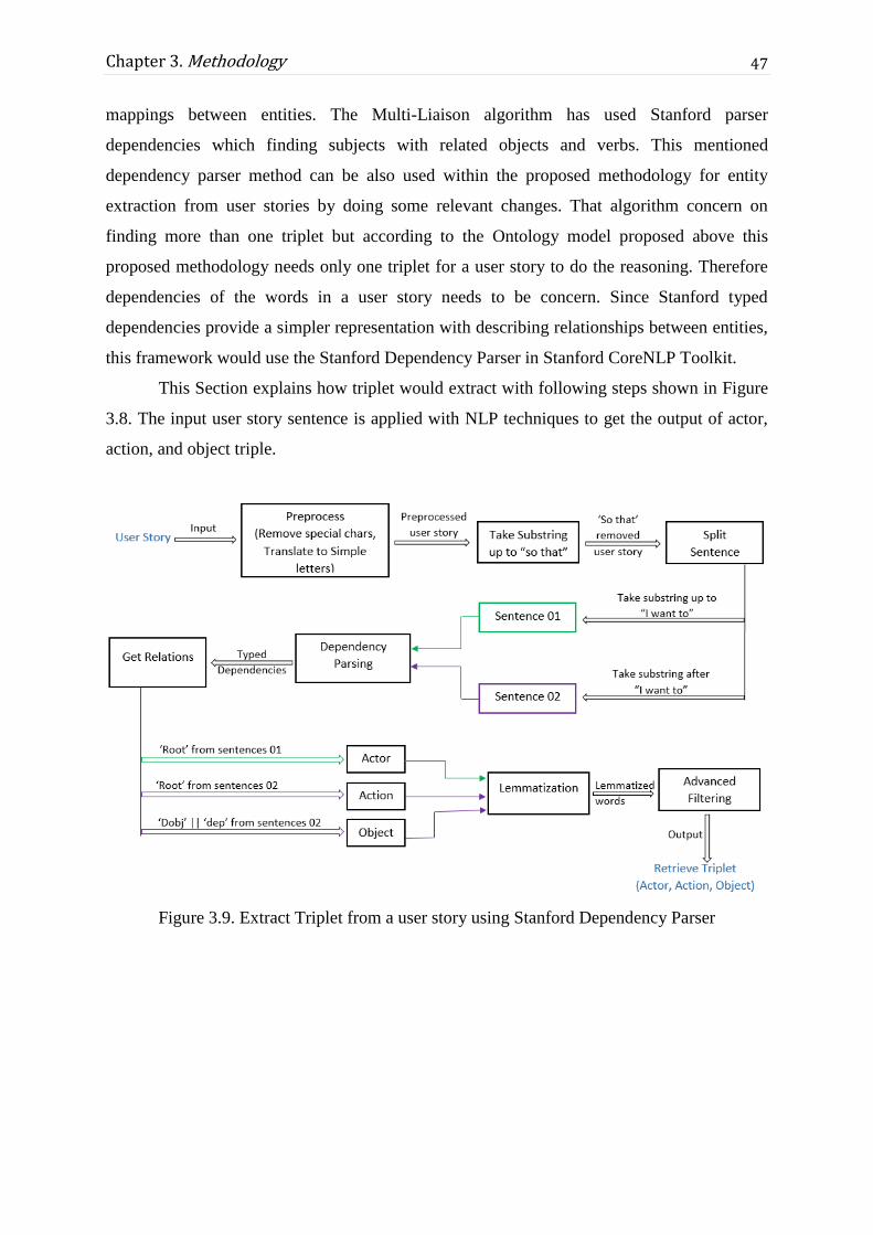
47
Chapter 3. Methodology
mappings between entities. The Multi-Liaison algorithm has used Stanford parser
dependencies which finding subjects with related objects and verbs. This mentioned
dependency parser method can be also used within the proposed methodology for entity
extraction from user stories by doing some relevant changes. That algorithm concern on
finding more than one triplet but according to the Ontology model proposed above this
proposed methodology needs only one triplet for a user story to do the reasoning. Therefore
dependencies of the words in a user story needs to be concern. Since Stanford typed
dependencies provide a simpler representation with describing relationships between entities,
this framework would use the Stanford Dependency Parser in Stanford CoreNLP Toolkit.
This Section explains how triplet would extract with following steps shown in Figure
3.8. The input user story sentence is applied with NLP techniques to get the output of actor,
action, and object triple.
Figure 3.9. Extract Triplet from a user story using Stanford Dependency Parser

48
Chapter 3. Methodology
3.6.1 Pre-Process
As shown in Section 3.6 a user story is represented in “As a [Actor], I want to
[Action]+ [Object], So that [some business value]”. The sentence after ‘So that’ substring
contains some business value that would be achieved with the success of action. Therefore in
such a user story, sentence after ‘so that’ string won’t take into consideration. In order to
remove that part, first the complete user story will translate into lowercase in English and
remove if there any special characters like punctuations or others. Then the ‘so that’ substring
is removed and the rest substring is only taken as the sentence.
Table 3.4. Pre-processing a user story
Original User story “As a User Admin, I want to add a new user group to the system,
so that I can add users to that group and manage them easily.”
After preprocessed “as a user admin I want to add a new user group to the system so
that I can add users to that group and manage them easily”
User story after remove
‘so that’ part
“as a user admin I want to add a new user group to the system”
3.6.2 Split Sentence
According to the Actor, Action, Object concept of the developed Ontology model,
only one triple from a user story need to be extracted. This leads to the requirement of a
dependency parser to get the dependencies between words. But to extract the exact actor,
action and object entities, the user story need to be split according to the method which this
thesis is proposing. So the user story is split into two substrings as sentence 01 and sentence
02 where sentence 01 contains the substring upto string ‘I want to’ and sentence 02 contains
the substring after string ‘I want to’. Each of these two sentences is then passed to the
Dependency Parsing step separately.
Table 3.5. Splitting a user story into separate two sub sentences
Pre-processed user story “as a user admin I want to add a new user group to the system”
Sentence 01 “as a user admin”
Sentence 02 “add a new user group to the system”

49
Chapter 3. Methodology
3.6.3 Dependency Parsing
The Stanford parser analyses and extracts the grammatical structure of the sentence
which indicates how the words are related to each other. It identifies the subject, object, verb
phrase between the subject and the object, and conditional statements. In this proposed
method, first get the syntactic dependencies of the sentence and a semantic graph of it and
then take typed dependency in that semantic graph. The output semantic graph and typed
dependencies for the sentence “As a Admin I want to add users to group.” are shown in
Figure 3.10 and 3.11 respectively.
Figure 3.10. Semantic graph representation using Stanford dependency parser
Figure 3.11. Typed Dependencies
As identified in chapter 2, among all the introduced 50 grammatical relations, for this
framework only few relations would be used since there is a particular way of writing a user
story. Typed Dependency is a relation between two words and each Typed Dependency
consists of a governor word, a dependent word, and a relation.

50
Chapter 3. Methodology
Example: dobj(add-7, users-8)
Here relation is ‘dobj’, governor word is ‘add’ and the dependent word is ‘users’.
Relation ‘root:root’
The root grammatical relation points to the root of the sentence and this root is the head of the
entire structure corresponds to a sentence [56]. According to them a fake node “ROOT” is
used as the governor.
Example: root (ROOT-0, want-5)
• Relation ‘dobj: direct object’
The direct object of a Verb Phrase is the noun phrase which is the object of the verb [56].
Example: dobj(add-7, users-8)
• Relation ‘dep: dependent’
When the Stanford dependency parser is unable to determine a more precise dependency
relation between two words it sets the relation as dependent.
Example: Here if a sentence contains an substring as “book a room’, then the relation
between the word ‘book’ and the word ‘room’ is unable to determine due to the ambiguity of
the word ‘book’. In such situations parser would provide relation as below.
dep(book-1, room-3)
In this dependency parser step, the two sentences splitted from the user story would parse
using the dependency parser and following relations in Table 3.6 are taken as actor, action,
object from the typed dependencies that dependency parser creates.
Table 3.6. Extracted relations as triplet from dependency parser
Actor Dependent word in the ‘root’ relation in sentence 01
Action Dependent word in the ‘root’ relation in sentence 02
Object Dependent word in the ‘dobj’ relation or ‘dep’ relation in sentence 02

51
Chapter 3. Methodology
3.6.4 Lemmatization
For grammatical reasons, sentences use different forms of a word. From the above
step, once the triplet is extracted from a user story the three entities may or may not matches
with the words given in the Ontology as Ontology refers to common set of vocabulary of
words. Therefore the retrieved entities need to be lemmatized where lemmatization refers to
the removal of inflectional endings only and to return the base or dictionary form of a word
[57]. An inflectional ending is a group of letters added to the end of a word to change its
meaning. So at the end of these steps, 3 lemmatized words as actor, action and object are
retrieved from a user story according to the dependency relations created by the dependency
parser.
3.6.5 Advanced Filtering
According to the dependency parser, the extracted 3 words are needed to be compared
with the Part-of-Speech (POS) tag [58] of those words. Stanford uses Penn Treebank and
there are 45 tags in the Penn Treebank tag set for English and it is shown in Figure 3.12.
Figure 3.12. Penn Treebank Part-of-Speech tagging [58]

52
Chapter 3. Methodology
• Actor Filtering
Since the actor entity is extracted from the relation ‘root’ in the sentence 01, it could be
either noun or a verb according to the given user story. But basically actor should be a noun
that is NN according to Figure 3.12. Therefore the POS tag of the lemmatized word actor
extracted from the previous step should be a noun. If the POS tag of that word actor is equals
to ‘NN’ then it is taken as the correct actor word and system would process further.
Example:
“As a add I want to create users in the group”
Here the word ‘add’ is extracted from the dependency parser since it is the root word
of the sub sentence “As a add”. But it is not a noun (NN) so to handle such cases here the
actor word ‘add’ should be compared with its POS tag. Since the POS tag of word ‘add’ is
not a noun the system would reject that user story sentence.
There are cases where actor can be either noun or the noun phrase of the sentence.
This actor being either noun or the noun phrase would be depend on the context of the
software product in different software companies. Here in the above mentioned actor
extraction method in this thesis, it has only considered on the noun word which is given from
the dependency parser and it is shown in Table 3.7.
Table 3.7. Extracted actor names and expected actor names
Sentence Expected actor word System extracted actor word
As an admin admin admin
As an user admin admin admin
As an admin user Admin user user
As an system administrator administrator administrator
As an registered user Registered user user
• Object Filtering
In the dependency parsing step objects are extracted from the relation ‘dobj’ or ‘dep’
from the sentence 02. Here ‘dobj’ is the direct object relation in the sentence and ‘dep’ is the
relation for words where parser cannot identify relation as described in above section. There
can be more than one ‘dobj’ relations and ‘dep’ relations in a given sentence due to different

53
Chapter 3. Methodology
other words. Here what actually needed is the exact word of the object which is directly
accessed by the extracted action word. Therefore in the typed dependencies, the dependent
word should be extracted according to the governor word. If the governor word is the same
word as the action word then that dependent word is the relevant object for that user story.
This word also needs to be compared with its POS tag and it should be a noun tag. Only if
these conditions satisfy then the system will process with the next steps with the extracted
triplets.
Figure 3.13. Typed dependencies extracted for the sentence “add members using member
list”
The above Figure 3.13 illustrates a situation where there are more than two direct
objects (members and list) have identified from the dependency parser. But the system wants
only the word ‘members’ which has the governor word as root word ‘add’. Therefore the
correct direct object word can be filtered by comparing the governor word with the root word
of that sentence.
According to the method mentioned above, the relevant entities are extracted from a
given user story as Actor, Action, and Object in a triplel form. Then those entities are passed
to the Ontology component for reasoning purpose and to drive the test cases of that user
story.
3.7 Test Case Generation Using Reasoning
The software requirement Ontology is the knowledge base for the generation of
positive test cases. Therefore this section describes the related reasoning logics that have been
applied to the Ontology for the derivation of test cases. The required positive test cases are
derived, based on the three major parameters which are extracted from the user stories as
described in Section 3.6. The parameter list is taken as actor, action, and object.

54
Chapter 3. Methodology
The use of parameter list provides the flexibility to achieve the desired output, which
is a test case. The first step of requirement Ontology traversal is to restrict possible paths
concerning the given three parameters. As mentioned in early sections for a given user story
relationships are coupled with actor, action and object inputs. In this first step the actor
parameter finds out the existence of the given actor within the Ontology. If it exists then
traverse through the Ontology to find what are the possible actions which have the
relationship with given actor. If any, compare actions with given action parameter and take as
the true path for the correct match with given action. Then find out the existence of given
object parameter according to the relationship between given actor and action. The result is
true for correct findings of relationships between given parameters. The false or unmatched
situations occurred with if the required relationship not mentioned in requirement Ontology.
This false situation is not eligible to generate any test case. The system provides another
searching mechanism through the hasSimilarWord property. It finds if a given actor or action
not directly matched finds a relationship for the similar word which indicates similar
meaning. Figure 3.14 depicts the correct path finding for a given parameters.
Parameters: Actor_A, Action_B, Object_A
Figure 3.14. Find Out Ontology path for given parameters
3.7.1 Identify subclass of an action
The Section 3.5.4 described that each action belongs to a subclass according to its
dependency on an object. The test case generation is directly coupled with this specific
behavior of the action. Therefore identification of subclass is vital for further reasoning. The

55
Chapter 3. Methodology
action which belongs to objectChange subclass needs to consider about data properties of
both action and related object. The action which belongs to objectNotChange subclass only
considers the data properties of given action.
3.7.2 Identify implicit relationships of an action
The implicit relationship is a dependency on one or more actions for a given action.
This relationship can be a one-way relationship or a two-way relationship. The developed
software requirement Ontology maintains this implicit relationship knowledge. Therefore this
reasoning mechanism is introduced to identify and extract of those related action entities.
The method checks if there exists hasDependency object property defined for the
given action. The result set may be an empty set or set with one or more related actions. If
any action instance has depended on another set of actions, then their properties and
relationships also should be examined to generate test cases, because that information is
essential to the consistency of the system. As mentioned in early sections the quality of the
system is examined through test cases, and those test cases should cover every possibility of
the relationship between system entities.
3.7.3 Extract data properties
The goal of this process is to extract the data properties concerning the given action
and object. The data property represents the core information of a test case. These data
properties are coupled with actions and objects in software requirement Ontology. According
to the given parameter list, data properties are the output list of a valid traversal of Ontology
graph.
There are two types of data properties,
1. Action Data Property: Describes characteristics of an action
2. Object Data Property: Describes features of an object
According to the methodology proposed in Section 3.5.4, the subclass of an action
decides the type of data properties need to be extracted. The objectNotChange class instances
only consider the action data properties. The objectChange class instances consider both
action data properties and object data properties relevant to the given action.
The Figure 3.15 summarizes above-mentioned reasoning and illustrates as a flow
diagram. Apart from the reasoning component, the flow diagram depicts a condition to find
hasPreCondition of an action. In this case system searched for preconditions of an action that
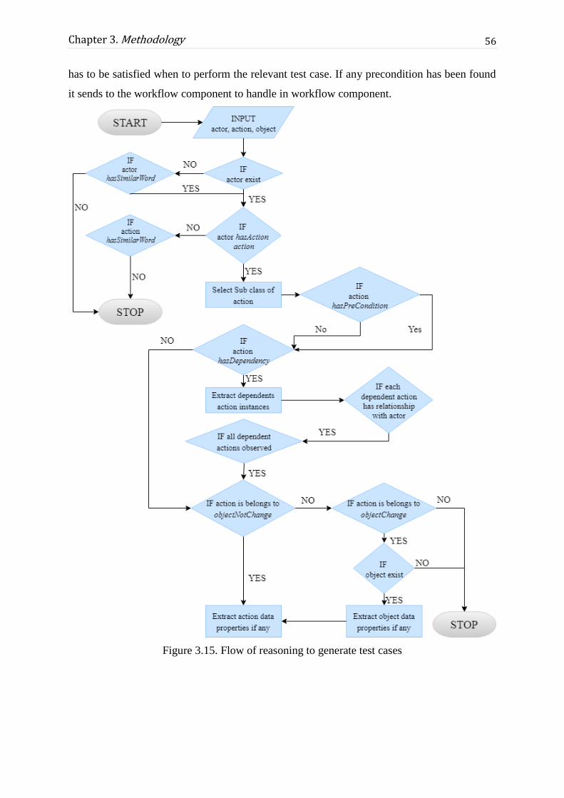
56
Chapter 3. Methodology
has to be satisfied when to perform the relevant test case. If any precondition has been found
it sends to the workflow component to handle in workflow component.
Figure 3.15. Flow of reasoning to generate test cases
57
Chapter 3. Methodology
3.8 Workflow for complete the test suit
The workflow component is used to complete the test suites which can be used to test
entire functionalities of the system. The aforementioned methodology generates positive test
cases using extracted action data properties and object data properties which cover a fair
amount of test cases. As mentioned in early chapters testing is vital to develop a quality
software product. Therefore test cases should cover the all the test objectives. This workflow
component enables the flexible modification and insertion of test cases of the system. The
automatically derived test cases may include unnecessary information or some essential
information may be missed. The system user can use this component to modify derived test
cases and add some new test cases or test steps. Also can set prerequisites of test cases
according to the extraction through hasPreCondition of given action instance.
Apart from the modifications and insertions, this workflow component provides
facility to maintain authoritative actions such as test suite recommendation and test suite
approval from relevant system users.
3.9 A Simple Example
In this section a sample user story is used to generate test cases with following the
above mentioned methodology. The user story is need to be written as the template discussed
in the Section 3.3 and it would be as following.
“As a User Admin, I want to update an existing group in the system, so that I can manage
users in that group easily.”
Then entity extraction steps will be applied as below. Sentence will be pre-processed and ‘so
that’ part will be removed from the user story.
“as a user admin I want to update an existing group in the system”
Then the user story will be splitted in to two seperate sub sentences as below.
Sentence 01: as a user admin
Sentence 02: update an existing group in the system
Then the each of the above two sentences are passed through the Dependency Parser and get
relations according to the typed dependencies as described in Section 3.6.3.
Sentence 1: Actor- admin

58
Chapter 3. Methodology
Sentence 2: Action- update
Object- group
Then these words are lemmatized in order to get the base form of those words as below.
Actor: admin -> admin
Action: update -> update
Object: group -> group
Then these 3 entities are transformed into advanced filtering for the purpose described
in section 3.6.5. POS tag of word ‘admin’ is NN (Noun) and since it is the correct tag for that
word the process continues. Then checks if there are any other direct objects retrieved and if
so, compare the object words with their governor word equals to action word ‘update’. Since
this user story does not having any other direct objects the object will be filtered as word
‘group’.
As the final output in the entity extraction method, (admin, update, group) parameters
are extracted and those will be passed to the Ontology for the reasoning and possible positive
test cases for this user story will be extracted as follows.
For the reasoning first check the existence of the three entities and the existence of the
relations between them. For the action update first check for hasDependency object property
and found that update has dependency on view. First consider the action view. It belongs to
objectnotchange subclass. Therefor first take the data properties of the action view as test
cases and then consider the properties of the action update. Then consider the class of the
action update. Here update is belongs to objectchange subclass, therefore data properties of
the extracted object is need to consider and its’ data properties are given as the other set of
test cases. Those test cases are shown below.
From action view:
view_top_N_views
View_all_objects
From action update:
Send_a_confirmation_message
Update_after_approval
From object group:
update group with non_existing_name
update group with non_empty_name

59
Chapter 3. Methodology
update group with name_with_numeric_values
update group with lengthy_name
update group with name_with_special_characters
update group with users
update group with user_roles
3.10 Summary
This chapter presented the proposed methodology for the research questions that were
identified concerning manual test case design in software testing phase. According to the
background analysis test cases, user stories and requirements were identified as main
terminologies that impact in the test design phase. Basically, the overall research intent was
to find a possible methodology for the automatic generation of test cases from user stories
written in the natural language based on an Ontology. A complete possible methodology for
developing an Ontology for software requirement domain, extracting entities from user
stories written in English and generation of test cases from user stories has been proposed
through this chapter.
According to this approach, the first main underlying concept is developing an
Ontology model for the software requirement domain. Practically any of the requirement
sentence can be recognized through the actor, action and object entities of that sentence and it
could be shown that test cases are also based on those entities. Therefore the developed
Ontology has its underlying concept model as actor, action, object and these were mapped as
classes in Ontology. The action class was categorized into two different sub classes
depending on whether the object changes once the action performed on that object. Object
and data properties were defined for each of those identified classes and some object
properties were defined to handle special cases like when there are implicit user stories or
entities having similar words.
In the next phase NLP techniques were used to extract entities from input user stories
in order to match them with the Ontology model concept developed. Therefore actor, action,
object entities were extracted in the form of triplet by using typed dependency relations
created from Dependency Parse tree. NLP method makes uses of parsing, lemmatization and
POS tagging techniques while extracting the triplet.

60
Chapter 3. Methodology
For the test case derivation, those extracted triplet is then passed to the Ontology and
reasoning would be done accordingly to retrieve the implicit information resides in that
developed Ontology knowledge base. Whether to extraction action data properties or object
data properties would depend on that identified two action categories. All the extracted
information are then sent to the workflow to build the complete test suite for a particular epic
scenario by allowing the user to do modifications as needed.
The feasibility of developing an Ontology from scratch is not possible and therefore
only one requirement area was taken into consideration to show this proposed methodology.
There comes the concept of involvement of an Ontologist into the software industry where
Ontologist has the responsibility for evolving the knowledge-based as required.

61
Chapter 4
System Design
4.1 Introduction
This Chapter describes the design of the system that automates the test case
generation based on Ontology according to methodology described in Chapter 3. This
Ontology based test case generation framework covers the Ontologist involvement in
software development, the system for test case generation and test case management
activities. The system architecture consists of user story component, NLP component,
Ontology component, reasoning component and workflow component as its main
components. These components are further explained under this chapter with discussing the
design aspects of the proposed methodology.
4.2 Design Goals
The goal of this proposed system is to generate functional positive test cases from
user stories within the Agile development process. The user story is the main requirement
representation mechanism in the existing agile process and it is currently used by the business
owner or business analyst to provide information about the functionalities of the system to the
developer.
The Ontology is the core component of the framework and this Ontology knowledge
base model is not designed for a specific application domain. Therefore the underlying
knowledge base in the developed Ontology can be evolved according to the requirements of
software product with the involvement of an Ontologist.
Functional positive test cases are the primary output of this web-based system. The
generated test cases can be managed through the system. The system aims to reduce the time
and effort in manual test case writing. Not only that but also the user can generate complete

62
Chapter 4. System Design
test suites from the system as their general test case design task and test suites can be taken as
an input to their test management tool.
4.3 Design Constraints
The main design constraint of the suggested framework is that Ontology-based test
case generation tool needs to be adapted to the existing Agile software development
workflow as much as possible. The solution preserved agile terminologies such as user story
and its characteristics. As described in Section 2.2.4, the story defines the requirements of the
system in a way while expressing the functionalities. The framework use implemented
Ontology knowledge model to derive positive test cases for a given user story. The proposed
test case generation system is thoroughly dependent on the software requirement Ontology
which is developed according to the information and observations collected through the
research study.
The primary input to the system is a user story written in the natural language where
in this approach it works only for English and it needs to follow the given format as described
in Section 3.3. For the user stories are given in the correct format only be able to generate the
relevant test cases through the system.
Another constraint is that the test case generation is a usable product of the introduced
framework. The tool provides user story management functionalities such as update and
deletes as well as provides management functionalities for test cases. The tool can be
developed as a plugin for project management tools such as Redmine, Jira. Project
management tool provides services such as estimations, requirement management, resource
allocation, team collaboration options and documentation. Then generated test suite through
the tool can be used as input for the test management tools such as Testlink. Test
management tools are used to maintain information on how testing is to be done, test
activities and status reporting of quality assurance activities. This system is a free-standing
tool which does not have any link with project management or test management tools.
Therefore tool can be integrated to those tools via integration mechanism such as plugin.

63
Chapter 4. System Design
4.4 System Design
The design constraints that discussed in above section 4.3 helped to frame the design of
Ontology-based test case generation tool.
Hence the overall design idea of the system is to automatically generate test cases
based on an Ontology where requirements are taken in the form of user stories and the user
stories are given as an input to the system. The Ontology domain is to build upon with
requirement terminologies in the current Agile development process in the software industry.
This developed Ontology would be reusable within any of the relevant software industry
which follows specified Agile practices with writing requirements as user stories. Therefore
if a particular company needs additional knowledge added to the developed Ontology, then it
could be done with an involvement of an Ontologist into current software development
process.
The input user story is provided by the relevant person who used to writes user stories
in the software company environment and usually that would be QA person. The introduced
framework accept this input if it is in the appropriate format and process them using NLP
techniques that have been described in above Section 3.6 to extract triplets in the form of
actor, action, object. Extracted triplets are used to query the Ontology described in above
Section 3.5. Properties from the Ontology are retrieved and produced as test cases which are
giving as the final output. The Figure 4.1 below shows the high-level picture of the system
design. Set of test cases for each user story under an epic are presented as a test suite. This
tool can be used as a user story management tool and the generated test suite can be passed to
a test case management tool as described in Section 4.3.
Figure 4.1. System design
The design of this suggested approach has adopted the principles, guidelines and
terminologies of agile software development which encourage the product owners,
developers and testers interest of use while keeping their familiarity within the process of
software development. Moreover, Object Oriented Principles [59] have also gained

64
Chapter 4. System Design
consideration with the design of the system. To build up the system design as shown in
Figure 4.1, the element components described in the next section are considered to be more
loosely coupled with achieving higher cohesion. Also the design has been considered using
Design Patterns [59] like MVC. Both the Encapsulation and Abstraction Object Oriented
Principles would be able to achieve through using this MVC design pattern in the design.
4.5 System Architecture
The System Architecture section provides an overview of this web-based system’s
dominant components and its architecture, as well as specifications on the interaction
between the system and the user.
The suggested research-based solution is designed with the idea of being an
independent component. As mentioned in chapter 2, most of the project management tools
that use to write and maintain user stories are web-based systems. Therefore the design of this
suggested system also considered on this aspect where such tools can be integrated with this.
The main components of the system were determined as Ontology component, NLP
component, Reasoning component, user story portal and database management system. The
intention is to focus on an application architecture rather than enterprise architecture since
applications architecture defines the interaction between application packages, databases
which specified on business and functional requirements while application architecture is one
of several architecture domains that form the pillars of enterprise architecture. Considering
the components identified for the proposed system, 3-tier architecture can be recognized as
the suitable application architecture. In 3-tier architecture these tiers represent different
aspects of presentation, business logic, and data access to the application. Above components
can be categorized into those layers accordingly and the overall system architecture can be
shown as in the Figure 4.2.

65
Chapter 4. System Design
Figure 4.2. System Architecture Diagram
Architecture diagram in Figure 4.2 describes how the components match with each
other in order to complete their works. User story portal component in presentation layer has
been used as the user interface to write user stories and it provides functionalities for view
and update of user stories. Generation of test cases for each user story can also be performed
by the user by this component. Once the test cases are generated from the system, the user
can update or delete them accordingly and that functionality provided by the test suite portal
in the presentation layer.
The Business layer consists of the business logic of the suggested solution. It contains
the Ontology component, NLP component and Reasoning component and it can be
considered as the core component in this architecture. The Ontology has been developed and
implemented according to the methodology described in Chapter 3 which is based on the
research described in Chapter 2. The concept of actor, action and an object in a user story
sentence was based on the developed Ontology and corresponded entities in user stories are
extracted through the NLP component. In the Reasoning component, reasoning techniques
will be applied on the knowledge base presented in the Ontology according to the extracted
inputs from user story and get the required result as test cases. These results are then passed

66
Chapter 4. System Design
to the test suite portal for the modifications that would need to be done. Test suite portal is in
the presentation layer where user has the ability to do the necessary changes by adding or
deleting relevant details in the derived test cases.
The Data Layer consists of the database and suitable logic. Data layer provides
simplified access to data stored in persistent storage. In here a relational database
management system has been proposed for providing efficient data access.
4.6 Summary
In this chapter it described the overall design of the proposed methodology discussed
in the previous chapter. To achieve the design goal of generating functional positive test
cases from user stories based on an Ontology module would be the target through several
components. So the architecture for this designed system can be recognized as a 3-layer
architecture that contains User story portal component and Test suite component in the
presentation layer while NLP component, Ontology Component and Reasoning component in
the Business layer and Database component in the Data layer. A user would be able to enter
user stories into the system using user story portal component. Core components in the
Business layer would derive test cases for that input user stories from the presentation layer.
NLP component will extract relevant entity triplet and passed it to the Ontology component
and then the Reasoning component would derive necessary test cases and passed them to the
Test suite component to be displayed to the user. The database component provides relevant
logics with a persistent storage needed within the user story and test suite components. All
these components are designed with the consideration of achieving Object Oriented
Principles while applying design patterns as far as possible.

67
Chapter 5
Implementation
5.1 Introduction
This chapter describes implementation details of the suggested Ontology-based test
case generation method, which realizes the system design explained in Chapter 4. It has
captured the fundamental implementation details with technologies and tools used. Further it
focuses on the Graphical User Interfaces used within the implementation of this proposed
tool and its features. According to the system architecture described in Chapter 4, the
implementation details of core components which are Ontology component, Triplet
extraction with user story portal, Test case generation and workflow component are
illustrated in this chapter.
5.2 Implementation Details
The system is a web-based solution because users can easily access the application
from any computer. Moreover, currently software companies use different tools for their
project management and test management. The proposed system is a supportive independent
solution to produce a bridge between project management and test management.
The Eclipse has been selected as the Integrated Development Environment (IDE) to
develop the web-based tool which is an open source IDE. The used package of IDE was
Eclipse Jee Neon for Java EE Developers. The Java, which is both a programming language
and a platform, has been selected for the development of Ontology-based test generation
system. The Java follow particular syntax and style for express its high-level object-oriented
programming language capability. Also, Java platform is a specific environment in which
Java programming language applications run. The proposed solution used Java Enterprise
Edition as its programming language platform. The Java EE selected because it provides API

68
Chapter 5. Implementation
and runtime environment for developing multi-tiered, scalable and secure network
applications. The proposed system follows three-tier architecture as described in Chapter 4.
Not only that, Java EE provides libraries for JDBC for access Ontology-based test case
generation database, Servlets and JSPs.
The Spring MVC framework has been used to develop the test case generation
system. Spring is a powerful Java application framework which provides a very clean
division between controllers, JavaBean models and views. The proposed system used
UserstoryController, TestcaseController, and LoginController as its controllers to handle
functionalities. Also used separate models and views accordingly as illustrated in Figure 5.1.
Other advantage of Spring MVC is its flexibility, which entirely based on interfaces and
Spring provides an integrated framework for all tiers of the application.
The Hibernate framework has been used to the development of the system to interact
with the database. Hibernate considered as an open source lightweight Object Relational
Mapping tool. The system used a relational database for manage user stories and test cases.
Therefore ORM simplifies the data creation, data manipulation and data access using
programming technique that maps the object to the stored data in the database. Automatic
Table creation is one of the main advantages that was gained using the Hibernate framework
within the system.
MySQL database has been used as the database, which is a free and open source
database management system. The following Figure 5.1 depicts the spring MVC and
hibernate architecture of the system according to the above-mentioned facts. The
implementation architecture can be divided into layers as spring controller, service layer, and
data access layer. The entire system implementation follows this architecture and will be
explained in 5.4, 5.5, 5.6 and 5.7 respectively.

69
Chapter 5. Implementation
Figure 5.1. Spring MVC - Hibernate architecture of the system

70
Chapter 5. Implementation
5.3 Graphical User Interface
The Graphical User Interface (GUI) provides the user interaction with the system of
the proposed framework. The GUI is created using Java Servlet Pages (JSP) which is a
technology for developing web pages. JSP supports for dynamic content and helps developers
to insert java code in HTML pages. Also JSP supports to collect input from users through
web page forms, existing records from relations database and software requirement Ontology.
The proposed system have been used JavaScript, JQuery and Bootstrap as front-end
frameworks for facilitates interactive GUI through JSPs.
5.3.1 GUI components
GUI has been developed keeping into consideration the process, terms and
functionality already used in Agile Software Development and Agile Testing. The GUI
consists of the following main components.
When an authorized user logged in to the system, home page should be like following
Figure 5.2 .This has functionalities for create new user stories and delete already created
unimportant user stories.
Figure 5.2. Home page

71
Chapter 5. Implementation
• User Story Form
User stories realized the features by describing the interaction between the system and the
user. The user story must clarify the role of the user, the feature to be implemented and the
benefit derived from the feature.
When a user needs to create a new user story, a user story template should be like Figure 5.3.
Epic No is the Id of the Epic that user story is belongs to. The pre-defined template for user
stories is as a [role], I want [functionality], so that [business value]. That should be entered in
the User Story Name field. Assignee, status and priority need to be entered for manage the
task. The user story may be used in different contexts. Each context and outcome of the user
story is called acceptance criteria. Those every field is taken to cover a full user story and to
improve the completeness of the system.
Figure 5.3. User Story Form

72
Chapter 5. Implementation
When an entered user story is clicked, its’ details are shown as Figure 5.4.
Figure 5.4. View Selected User Story
Entered user stories can be Edit or Delete by clicking the user story to view. Those
functionalities were given to improve the flexibility of the system. A user can save user
stories without generating the test cases at the same time and can generate test cases when
needed. Figure 5.4 depicts the filled user story which can be used to generate test case if not
yet generated. Also, the system provides functionalities for editing and deleting user stories
which have been already entered.
• Test case management
Generated test cases are shown as a test suite. The relevant test cases can be viewed
by clicking on the user story. If the generated test case is not valid, an authorized user can
delete or modify it to a valid one. New missing test cases also can be added to the system.
Figure 5.5 represents the already generated test suites which are a collection of user stories as
shown in Figure 5.6. The Figure 5.7 depicts the generated test cases for each relevant user
story.

73
Chapter 5. Implementation
Figure 5.5. Test Suite for Epics
Figure 5.6. User Stories in the Epic
Figure 5.7. Test Cases for a Relevant User Story

74
Chapter 5. Implementation
5.4 Implementation of Ontology
In Section 3.5 of the Chapter 3 Methodology, overall Software Requirement Ontology
has been discussed. The implementation of Ontology and used technologies are discussed
here.
The Ontology has developed using a tool called protégé in OWL language. The
primary purpose of the Ontology is to classify things regarding semantics, or meaning.
Classes and subclasses, instances of which in OWL are called individuals are used to achieve
this in the OWL. The individuals that are members of a given OWL class are called its class
extension. A class in OWL is a classification of individuals into groups which share common
characteristics. If an individual is a member of a class, it tells a machine reader that it falls
under the semantic classification given by the OWL class. Individuals in OWL are related by
properties. There are two types of properties in OWL as Object properties which relate
individuals of two OWL classes and Data properties which relate individuals of OWL classes
to literal values. Figure 5.8 depicts segment of implemented Ontology file in RDF format.
Figure 5.8. Part of RDF file
5.4.1 OWL and RDF
RDFS and OWL have been used to encode RDF data with semantic metadata.
Therefore OWL is based on RDF and OWL Ontologies are RDF documents. OWL provides
sufficient expressive richness to be able to describe the relationships and structure of entire
worldviews or the so-called terminological construct in description logics. At the level of
OWL Ontologies, RDF can capture virtually any relationship and aspects. RDF is expressed
as a simple subject–predicate–object “triples” and substitute verb for predicate and noun for
75
Chapter 5. Implementation
subject and object. OWL is a way of adding semantic richness to RDF. Among other things,
this allows automated reasoning/inferencing and represents using RDF triples and typically
expressed using RDF/XML syntax. RDF defines the way how to write things while OWL
defines ways what to write. RDF is a specification which tells how to define triples. The
problem is that RDF allows defining everything. If the declaration is as follows, it will allow
by the RDF.
Subj predicate object
Alex Eats Apples
Apples Eats Apples
Apples Apples Apples
When such triples are written with RDF, they form valid RDF documents. However,
these are semantically incorrect and RDF cannot help to validate what have written. This is
not a valid Ontology. OWL specification defines precisely what you can write with RDF to
have a valid Ontology. Therefore when creating the Ontology and retrieving its data, both
OWL and RDF are needed.
RDF work as a common framework and vocabulary for representing instance data, describing
simple data structs to complete vocabularies/Ontologies for processing and inferencing rules.
It is an emergent model. It begins as simple “fact” statements of triples as described above, so
that may then be combined and expanded into ever-more complex structures and stories. As
an internal, canonical data model, RDF has advantages over any other approach. It can
represent, describe, combine, extend and adapt data and their organizational schema flexibly.
5.4.2 Protégé Tool
As the Ontology editor, Protégé the most famous editing tool has been used. Protégé
is a feature-rich Ontology editing environment with full support for the OWL. It is a
downloadable, open-source, platform independent tool which requires a Java Runtime
Environment developed by the Stanford University School of Medicine to acquire, represent,
and process information about human health. Protégé provides a consistent rendering of
Ontology entities, using URI fragments or annotation values. In Protégé classes and
individuals are represented as rounded squares and properties are drawn as arrows. The
shapes and arrows have labels that hold the name of each class or property, except the
hasSubclass relationship, which is given unlabelled to avoid cluttering the visualization.

76
Chapter 5. Implementation
5.5 Implementation of Entity Extraction with NLP
techniques
Implementation of this was also based on the architecture shown in Figure 5.1. By
following Spring MVC framework, as shown in that diagram the development classes and
interfaces were defined as needed.
The primary input to the system would be user stories and once a user story was
entered into the system, then test cases for that particular user story could be created. A user
can enter details of user stories while creating a new user story and details can be edit and
delete if needed since this is an agile environment. All those methods are accessed through
UserstoryController.java class. These methods are implemented in the
UserstoryServiceImpl.java class which implements the UserstoryService.java interface.
These details would be saved within the database according to the methods implemented in
the UserstoryDaoImpl,java class which implements the UserstoryDao.java interface.
When the user story has written, then if the user wants test cases can be generated. To
create test cases, entities from the user story need to be extracted. ExtractTriplets() method is
implemented in the EntityEctractorServiceImpl.java class and it makes use of the Stanford
CoreNLP toolkit libraries for the NLP techniques needed. Stanford typed dependencies
parser, lemmatization, POS tagging techniques was used for this implementation.
Following Figure 5.9 represent the implementation details regards to the user story
creation and entity extraction.

77
Chapter 5. Implementation
Figure 5.9. The classes of the user story portal and Entity Extraction
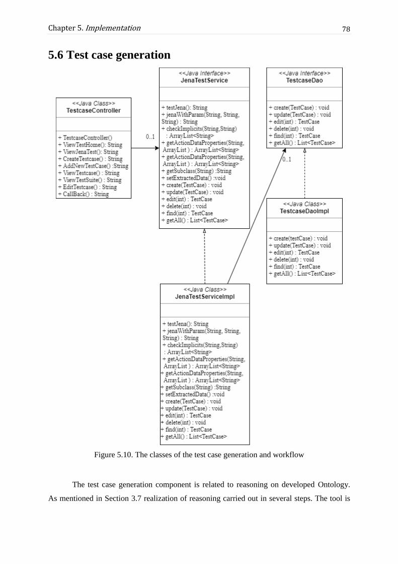
78
Chapter 5. Implementation
5.6 Test case generation
Figure 5.10. The classes of the test case generation and workflow
The test case generation component is related to reasoning on developed Ontology.
As mentioned in Section 3.7 realization of reasoning carried out in several steps. The tool is

79
Chapter 5. Implementation
introduced as a web-based solution which is build based on Java EE. For the reasoning and
derivation of test cases, Apache Jena API has been used. Apache Jena is a free and open
source Java framework for building semantic web and linked data [60]. The web-based tool
used apache-Jena 3.6 library to provide the service. This library contains the APIs, SPARQL
engine, the TDB native RDF database and different types of command line scripts and tools.
According to the Spring MVC framework separate controller class namely,
TestcaseController.java used to control the functionalities of test case generation. The Figure
5.8 depicts how the TestcaseController class process with service class to perform the
reasoning on Ontology. JenaTestService.java class declare the methods and
JenaTestServiceImpl class implemented the method for searching and retrieving knowledge
relevant to test cases from the software requirement Ontology.
JenaTestServiceImpl uses the Jena API for selecting and adding test cases. It provides
methods for loading OWL Ontology and retrieves relevant properties according to the given
parameters. The underlying logic has been described in Section 3.7. In this class SPARQL
query language has been used to query the results from the Ontology. SPARQL queries
applied on OWL Ontology which was saved in RDF format. SPARQL provides explore data
by data by querying unknown relationships and Transform RDF data from one vocabulary to
another. Several numbers of queries have been used to derive test cases according to the
mentioned methodology in Section 3.7. The JenaTestServiceImpl provides methods for
restructuring the test cases according to retrieved properties and including methods for add
other features such as precondition, steps and expected result. This realization of class
functions related to the test case generation is shown in Figure 5.10.
5.7 Workflow component
The workflow component is more related to test case management. The component
uses database management functionalities to maintain test cases, approval of generated test
cases. As mentioned in Section 5.1.2, derived test cases are managed by this component.
Modification to the test cases, ignore additional test cases, insert new test cases, set
prerequisites of test cases which have extracted in reasoning component, manage approval of
test cases, the complete creation of test suite and database operations are considered as
principal operations of this component. The JenaTestServiceImpl provides methods for
approve test case as a valid test case and creates a complete test suite. Then TestcaseDaoImpl
provides methods for database activities such as insert, delete, update and delete. MySQL

80
Chapter 5. Implementation
relational database has been used to manage test cases and test suites. Figure 5.8 depicts
methods of database activities of TestcaseDaoImpl. The use of workflow component
encourages the flexibility and the maintainability of the proposed system.
5.8 Summary
To implement this web based system Eclipse IDE and Java EE has been used. The
Spring MVC framework has been used to develop the test case generation system where
Hibernate has been used as the ORM tool between the RDBMS and the object classes
implemented.
For the implementation of Ontology, OWL language has been used where OWL
Ontologies represented as RDF documents. As the Ontology editor, Protégé has been used
which has a feature-rich Ontology editing environment with full support for the OWL and it
presents as a downloadable, open-source product.
The user story form has been implemented in a way such that the system user can
enter details of user stories and can make modifications or deletions as needed. To retrieve
relevant test cases for a written user story then entity extraction need to be done and to
implement that Stanford CoreNLP toolkit was used while making use of its libraries. Stanford
typed dependencies were used to identify the relations between the word in a given sentence.
All these were implemented using Spring MVC framework with defining relevant methods
inside java classes while Hibernate supports as the connection between the database and its
model classes.
The system implementation used Apache Jena API for manipulating OWL Ontology
and SPARQL for reasoning. The Java methods have used to restructure derived test cases.
The Java Hibernate framework used for manages test cases and test suite for providing usable
end to process to the user. The primary objective of this system implementation is to reduce
the manual involvement between requirement representation and test case designing in
current software development industry.
81
Chapter 6
Results and Evaluation
6.1 Introduction
This Chapter describes present results of the proposed framework. These results can
be divided into results of Ontology-based test case generation framework (base analysis) and
user evaluation of proposed framework in software development industry. As mentioned in
previous chapters the proposed solution has focussed on the generation of positive test cases.
Therefore the analysis is based on whether test cases provide good test case coverage and if
the system can generate accurate and quality test cases. The base analysis evaluates the
performance of the system for the group management scenario of the specific end product of
well-known software company in Sri Lanka.
The base analysis based on following aspects: triplet extraction from user stories,
software requirement Ontology evaluation, Ontology-based test case generation system
evaluation. User evaluation has been conducted to analyze system generated test case
coverage with manually written test cases by users and analyze feedback to the system by
experienced professionals.
6.2 Datasets
Two datasets were used for the evaluation of the system. To evaluate the NLP
component described in Section 3.6 have used a set of user stories (Dataset-1). This dataset
has been attached in Appendix B. The Dataset-2 was gained from user stories of Group
management epic of the developed product by a software company and user stories of HR
management product by another software company. These user stories have been used to

82
Chapter 6. Results and Evaluation
generate test cases automatically. The automatically generated test cases have been compared
with manually written original test cases for the evaluation.
6.3 Software Requirement Ontology Evaluation
Ontology evaluation is a significant problem that must be addressed if Ontologies are
to be widely adopted in the semantic web related applications. In general, evaluation of
Ontology is a challenging task. There is no standard evaluation measures like precision and
recall which are used in information retrieval or accuracy measure used in machine learning.
The unsupervised nature of Ontology learning further makes the evaluation process complex.
Users facing a multitude of Ontologies need to have a way of assessing them and deciding
which one best fits their requirements the best. Various approaches to the evaluation of
Ontologies have been considered in the literature, depending on what kinds of Ontologies are
being evaluated and for what purpose [61]. Four identified approaches are as follows:
• Comparing the Ontology to a “golden standard”
• Using the Ontology in an application and evaluating the results
• Comparisons with a source of data (e.g. a collection of documents) about the domain
to be covered by the Ontology
• Evaluation done by humans
It is further suggested that it is practical to focus at different levels of the Ontology
separately in evaluation rather than directly evaluate the Ontology as a whole because of the
complex structure of an Ontology [61]. The Table 6.1 illustrates how these different levels of
Ontology development can be evaluated by each of the evaluation approaches stated above.
Table 6.1. An overview of approaches to Ontology evaluation [61]
Level Gold
standard
Application
Based
Data
driven
Human
evaluation
Lexical vocabulary concept data X X X X
Hierarchy, taxonomy X X X X
Other semantic relationships X X X X

83
Chapter 6. Results and Evaluation
Context, application X X
Syntactic X X
Structure, architecture, design X
This research use application based evaluation techniques out of the four Ontology evaluation
techniques above.
6.3.1 Application-Based Evaluation
The Ontology will be used in some application or task. The outputs of the application,
or its performance on the given task, might be better or worse depending partly on the
Ontology used in it. Therefore a good Ontology is contributing for a good result of an
application. Ontologies may, therefore, be evaluated simply by plugging them into an
application and evaluating the results of that application. Therefore by evaluating the results
of the Ontology-Based Test Case Generation Framework, the developed Ontology can be
evaluated.
6.3.2 Reasoner Based evaluation
The Ontology is also can be evaluated by using reasoning service offered by reasoners
plugged in Protégé. The main benefits of the services are computing the classes’ hierarchy
and logical consistency checking. Here HermiT 1.3.8 reasoner has been used as shown in
Figure 6.1.

84
Chapter 6. Results and Evaluation
Figure 6.1. Protégé with no reasoner
Protégé has HermiT as its default reasoner to compute the OWL. The Ontology has been
evaluated via HermiT 1.3.8. The following Figure 6.2 shows the inferred hierarchy graph.
Figure 6.2. Protégé with HermiT 1.3 Reasoner

85
Chapter 6. Results and Evaluation
6.4 Analysis of Triplet Extraction
This analysis is based on the NLP component of the proposed system as described in
Section 3.6. The principal objective of this analysis is to identify for what extent triplet
extraction of the system performs well. Triplet is considered an actor, action and object which
are taken as the input of reasoning.
6.4.1 Analysis of actor
The Advanced filtering method discussed in Section 3.6.5, the system identifies a
valid actor word should be a noun which is extracted based on Stanford Dependency Parser
[56]. From the sample data set identification of actor as a noun was 89% and 11% was
identified as not a noun.
The nature of an actor word being either the noun or the noun phrase depends upon
the context of the software product as mentioned in actor filtering topic under Section 3.6.5.
According to the data set, valid actors for the system can be calculated by the following
equation.
Valid Actor for the system = 𝑵𝒐.𝒐𝒇 “𝒄𝒐𝒓𝒓𝒆𝒄𝒕𝒍𝒚 𝒂𝒅𝒅𝒓𝒆𝒔𝒆𝒅” 𝒂𝒄𝒕𝒐𝒓𝒔
𝑵𝒐.𝒐𝒇 𝒂𝒍𝒍 𝒂𝒄𝒕𝒐𝒓𝒔× 𝟏𝟎𝟎% = 65%
No. of “correctly addressed” actors: Actor words that do not affect the functionality of
software product and identified from the noun of noun phrase in user story.
No. of all actors: Actor words that identified as a noun from the user story dataset
According to the results, 65% actor words have been observed as a valid input to the
proposed solution. However, 35% of actor words have affected the functionality of the
software. This situation will affect the generation of test cases because the extracted actor
word may or may not exist in the Ontology.

86
Chapter 6. Results and Evaluation
6.4.2 Analysis of action extraction
According to the comparison between extraction of action from the implemented NLP
component and manual identification of action from user stories, the accuracy of the correctly
extracted actions can be identified as follows.
From the comparison of actual action of user story with implemented NLP component
results,
Action Accuracy = 𝑵𝒐. 𝒐𝒇 "𝑪𝒐𝒓𝒓𝒆𝒄𝒕" 𝒂𝒄𝒕𝒊𝒐𝒏𝒔
𝑵𝒐. 𝒐𝒇 𝒂𝒍𝒍 𝒂𝒄𝒕𝒊𝒐𝒏𝒔× 𝟏𝟎𝟎% = 88%
No. of Correct actions: Total number of actions correctly extracted by NLP component as
obtained in user stories which defined the functionality of the requirement
No. of all actions: Total number of actions obtained in user stories which defined the
functionality of the requirement.
The system captures the action words as the root node of the given sentence as
discussed in Section 3.6.3. There are words having multiple expressions with different
meanings that cause ambiguity. Actual action word should be a verb but there are cases
where actual action word has more than one meaning with different POS tags. In such cases
the whole sentence becomes ambiguity and the dependency parser does not identify the word
that system needs as the root relation. Therefore such scenarios that makes a sentence
ambiguity has not taken care through this method.
Examples: As an admin, I want to view users of the system.
Here the substring of “view users of the system” is ambiguous because of the word
‘view’. The word ‘view’ can be taken as either noun or a verb and it depends on the sentence
meaning that want. Though the word ‘view’ should be the action word of this sentence,
because of the ambiguities it has not taken care through the system.
6.4.3 Analysis of object extraction
According to the comparison between extraction of object from the implemented NLP
component and manual identification of object from user stories, the accuracy for the
correctly extracted object can be identified as follows.

87
Chapter 6. Results and Evaluation
From the comparison of actual object of user story with implemented NLP component
results,
Object Accuracy = 𝑵𝒐. 𝒐𝒇 "𝑪𝒐𝒓𝒓𝒆𝒄𝒕" 𝒐𝒃𝒋𝒆𝒄𝒕𝒔
𝑵𝒐. 𝒐𝒇 𝒂𝒍𝒍 𝒐𝒃𝒋𝒆𝒄𝒕𝒔× 𝟏𝟎𝟎% = 81%
No. of Correct objects: Total number of object words correctly extracted by NLP component
which are directly accessed by extracted action word in user stories.
No. of all objects: Total number of object words which are directly accessed by extracted
action in user stories.
As described under object filtering topic in section 3.6.5 it is observed that the
accuracy of identification of an actual object of a sentence is directly based on the action
word identified in that sentence. In this proposed methodology for object extraction, it only
finds for the direct object relation or the dependent relation. Here apart from the ‘dobj’
relation, ‘dep’ relation was used to handle ambiguities between the action word identified and
its noun object to some extent. However, still there are cases where more than one dependent
words are connected to the action word as objects. Among all these object words the system
is not in a possible state to find the exact object word that related to the action word.
Also when the action word is preceded by a preposition word attached to the actual
object word then the ‘dobj’ relation is not further identified by the dependency parser and it
provides another relation like ‘nmod:for’ which is related to preposition ‘for’ and that noun
object ‘order’ word as below example Figure 6.3.
Figure 6.3. Typed dependencies extracted for sentence “pay for my order”
Therefore such cases related with prepositions are not taken care with this proposed
methodology of entity extraction.

88
Chapter 6. Results and Evaluation
6.5 Ontology based test case generation system evaluation
This is the primary evaluation of the base analysis that has been done with
implemented Ontology and test case generation system. According to the involvement of
Ontologist as described in Section 3.4 the implemented Ontology has been used as the
knowledge base. The reasoning principles discussed in Section 3.7 have been applied with
inputs provided through NLP component as discussed in Section 3.6. The performance and
output of generated test cases depend on these mentioned methodologies. The dataset-2
which was set of user stories as shown in Figure 6.4 used as inputs for this evaluation.
Figure 6.4. Set of user stories used for the evaluation purpose
The test cases generated by the system for this dataset are shown in Figure 6.5 and 6.6. The
test cases generated for each and every user story are shown in these Figures with relevant
user story ID.

89
Chapter 6. Results and Evaluation
Figure 6.5. Test cases generated by the system for the dataset-2 from user story ID 1-5

90
Chapter 6. Results and Evaluation
Figure 6.6. Test cases generated by the system for the dataset-2 from user story ID 6-12
Figure 6.7 depicts the comparison between all the test cases generated manually with positive
test cases generated automatically by the system according to the each given user story.

91
Chapter 6. Results and Evaluation
Figure 6.7. Comparison between all the test cases generated manually with positive test cases
generated automatically by the system
From this comparison overall coverage of the test case generation system can be calculated as
follows,
Overall coverage = 𝑨𝒍𝒍 𝒕𝒉𝒆 𝒑𝒐𝒔𝒊𝒕𝒊𝒗𝒆 𝒕𝒆𝒔𝒕 𝒄𝒂𝒔𝒆𝒔 𝒂𝒖𝒕𝒐𝒎𝒂𝒕𝒊𝒄𝒂𝒍𝒍𝒚
𝑨𝒍𝒍 𝒕𝒉𝒆 𝒕𝒆𝒔𝒕 𝒄𝒂𝒔𝒆𝒔 𝒎𝒂𝒏𝒖𝒂𝒍𝒍𝒚× 𝟏𝟎𝟎% = 39%
All the test cases manually: Total number of all test cases written by users manually for each
given user story
All the positive test cases automatically: Total number of all positive test cases generated by
system for each given user story
Figure 6.8 represents the comparison between all the positive test cases generated manually
with positive test case generated automatically by the system for each user story.

92
Chapter 6. Results and Evaluation
Figure 6.8. Comparison between all the positive test cases generated manually with positive
test case generated automatically by the system
From this comparison positive coverage of the test case generation system is calculated as
follows,
Positive coverage = 𝑨𝒍𝒍 𝒕𝒉𝒆 𝒑𝒐𝒔𝒊𝒕𝒊𝒗𝒆 𝒕𝒆𝒔𝒕 𝒄𝒂𝒔𝒆𝒔 𝒂𝒖𝒕𝒐𝒎𝒂𝒕𝒊𝒄𝒂𝒍𝒍𝒚
𝑨𝒍𝒍 𝒕𝒉𝒆 𝒑𝒐𝒔𝒊𝒕𝒊𝒗𝒆 𝒕𝒆𝒔𝒕 𝒄𝒂𝒔𝒆𝒔 𝒎𝒂𝒏𝒖𝒂𝒍𝒍𝒚× 𝟏𝟎𝟎% = 48%
All the positive test cases manually: Total number of all the positive test cases written by
users manually for each given user story
All the positive test cases automatically: Total number of all positive test cases generated by
system for each given user story
To measure the validity or the accuracy of the generated test cases by the system was done by
comparing the actual test cases provided software companies to relevant user stories. The
accuracy was 100% and it indicated that all the generated test cases are valid to test the
software product.

93
Chapter 6. Results and Evaluation
6.5.1 Discussion of the System Evaluation Results
Within the system evaluation process, the primary task was to generate positive test
cases based on the Ontology. The implementation of Ontology model was explained in
Section 3.5 and the Ontology knowledge base can be evolved through the involvement of an
Ontologist as described in Section 3.4. The implemented solution was able to generate
positive test cases and for the given scenario positive test case coverage was 48%. However,
with the involvement of Ontologist to the agile development, Ontologist can capture every
requirement and evolve the Ontology according to them. Therefore positive test case
coverage can be increased up to 100% which will be directly affected the overall coverage of
test cases. In some cases according to the information included in software requirement
Ontology knowledge the validity or the accuracy of the test cases may be varied. Therefore
system provides workflow component for tracing these deviations and correct or ignoring
additional test cases.
6.6 User Evaluation
The user evaluation of the proposed system was done with five software quality
assurance professionals with testing knowledge and experience. 100% participants had over
one year of testing experience. Each participant was given five user stories which are relevant
to the Group management epic of a developed product by a software company to write test
cases manually. Also, same user stories were given to the Ontology-based test case
generation by each user to generate test cases automatically. The key parameters examined
from the evaluation were positive test case coverage by the system with manually written test
cases as the system was developed to generate positive test cases. Also the validity of
automatically generated test cases were checked with users’ experienced.
The Figure 6.9 depicts the user stories of given scenario, And Table 6.2 represents the
number of all test cases written and the number of all positive test case included in all test
cases by each user for user story IDs from 1- 5 in Figure 6.9. The total number of test cases
generated by the system according to the given stories was 28. Figure 6.10 depicts the
percentage of automatically generated test case coverage with test cases generated by each
user manually.

94
Chapter 6. Results and Evaluation
Figure 6.9. User stories given for the user evaluation
Table 6.2. The number of all test cases manually written by each user and the number of all
positive testcase among them
Manual
User
1 2 3 4 5
No. of all test cases 43 49 41 51 39
No. of positive test cases 39 41 33 38 33
Figure 6.10. Automatically generated test case coverage vs test cases generated by each user
manually
According to the analysis of automatically generated test cases with actual test cases
written by users the automatically generated test cases had an accuracy of 100%, which

95
Chapter 6. Results and Evaluation
means that system automatically generated valid test cases. In other words, the test cases
generated by the system should be included as a test case when test the software product.
The Figure 6.11 depicts that all the participants selected the automatic test case
generation method to preferred method for generating the test cases concerning time-saving,
lesser effort and reusability. One user mentioned that manual method of generating test cases
required less effort due to experienced gained by the user will be increased with time.
Figure 6.11. User preference: Manual vs Automatic test case design
The Table 6.3 summarizes the feedback collected from the five users who have involved in
test case generation for the given user stories.
Table 6.3. User Responses to survey question
Rate satisfaction level of
test coverage by
automated system
Extremely
satisfied
Highly
satisfied
Moderately
satisfied
Lesser
satisfied
Not
satisfied at
all
1 4 0 0 0
Rate the accuracy or
validity of generated test
cases
Extremely
accurate
Very
accurate
Moderately
accurate
Slightly
accurate
Not
accurate at
all
2 3 0 0 0
Rate the ease of use of
this system by a user
with no testing
experience
Extremely
easy
Very
easy
Moderately
easy
Slightly
difficult
Extremely
difficult
0 5 0 0 0

96
Chapter 6. Results and Evaluation
6.6.1 Discussion of the User Evaluation
The user evaluation was conducted with the assistance of only five users who have
testing experience over one year. According to their feedback and preferences, the introduced
methodology through the system senses good impact towards software industry. However,
this situation may be changed with professionals who have more experience in testing.
The users have indicated that the effort will be reduced by using this tool while
increasing the time saving and reusability. The users mentioned that the time taken to test
case generation using the system is lesser, but they had the doubt about the evolvement time
of the Ontology since it depends with the time taken by the Ontologist at their company.
However, it is observed that if the existing Ontology has been developed very accurately and
well-populated according to the requirements, it produces a considerable advantage to
software development with cost factors such as monetary, time and effort.
6.7 Findings of the Base Analysis and User Evaluation
For the conclusion, if the discussion summarizes the findings and validating claims
made in Section 1.4, Aims and objectives. The proposed methodology developed an
Ontology model for software requirement domain which can be evolved through the
involvement of Ontologist in Agile software development. It is observed that considerable
amount of effort has been reduced since it will encourage the QA engineers to draw their
attention and effort towards critical areas of the software product. According to the collected
information from software companies, the conflicts between user stories and test cases have
been reduced with this presented system because test case management and user story
management can be done up to some satisfiable extent using the system. The identified
drawbacks can be handled with future developments, and it will produce higher test case
coverage while being faster and cheaper. It is also observed that reusability of software
requirement has been improved through the Ontology and reusability of test cases also be
increased.

97
Chapter 7
Conclusion and Future Work
7.1 Conclusion
Design test cases manually is a complicated process and very time consuming and
costly phase in software development life cycle. In this thesis, a framework has been
designed and implemented to auto-generate positive test cases using natural language
processing and based on an Ontology for software engineering products in Agile
development.
As the input to the framework, user stories were taken with relevant to the given
template format which is popular in Agile development. An Ontology was developed from
the scratch due to the unavailability of an existing Ontology in the software engineering,
requirement domain. The Ontology model concept was developed based on actor, action and
object triplet which directly affected the test cases. To extract the relevant data from the pre-
developed Ontology those mentioned triplets were needed to extract from the user stories
which were written in natural language. Therefore the user story was processed using NLP
techniques to extract the entities which are essential to test case generation. Then the
extracted triplets are used for Ontology reasoning to extract properties of relevant instances in
the Ontology. Those properties were presented as test cases after some modifications. The
generated test case was presented as a test suite and passed through a workflow to customize
the output of the framework by removing faulty test cases and adding any missing test case.
The final output of the framework is a set of positive test cases.
According to the objectives had at the beginning of this work, most of them have been
covered at the end of this work. A common feasible template has been introduced, an
Ontology has been developed and most of the test cases were generated using identified NLP
techniques. Because of the developed Ontology, the risk gain due to shifting of employees is

98
Chapter 6. Results and Evaluation
reduced. When Identifying the actor of some user stories, this work has shown some conflicts
and suggestions to solve those conflicts, are discussed in future work for automating test case
generation section.
This research study has concluded that automatic generation of test cases based on an
Ontology is a feasible approach and user stories can use to test case generation after applying
NLP techniques. At the end of this research work, a new concept has introduced by forming
the role of an Ontologist into the current software industry which follows Agile practices.
7.1.1 Contributions of Automatic Test Case Generation
Framework
This framework decreases the time and effort taken to write test cases manually by
generating positive test cases automatically and increase the reusability of generated test
cases where the Ontology can be taken as a generic solution for a specified epic.
This work has used Stanford Dependency Parser for entity extraction by considering
the grammatical structure of the sentences. The parser has been used in a different approach
as the intention was to extract the most important actor, action and object from a user story
which need for the test case generation. To achieve this intention, Stanford Dependency
Parser has been used with a separately introduced method along with its grammatical
relations, lemmatization and POS tagging techniques.
7.2 Future Works
At the end of this work, following future works have been identified as to fine tune the
framework and the generated test cases based on the Ontology.
7.2.1 Evolve of Ontology
To use this system as a generic solution, evolvement of the Ontology is needed since
this work has developed only for group management scenario. The Ontology can be evolved
further, or it can be separately implemented as a new Ontology using the Protégé tool. The
Ontology implementation and engage in the evolving process should be done by an
Ontologist who has the basic knowledge about Ontology model concept. Therefore the role of
the Ontologist would become important in the industry who follows agile development
methodology. After evolving the Ontology by considering requirements of many different

99
Chapter 6. Results and Evaluation
systems, Ontology becomes rich with knowledge and this can be reused as a generic solution
to generate test cases for many software development products.
7.2.2 Enhance Actor Identification
This work has some conflicts of extracting actor for some situation. As an example,
“Registered user” is extracted as “user”. However, the word “Registered” is needed for test
case generation if there are different kinds of users such as “Unregistered user”. This work
was used Stanford Dependency Parser and POS tagging for triplet extraction. For the
extraction of the actor, only the noun was taken after applying POS tagging to the first
sentence gained by splitting the user story into two strings. The suggestion to solve this issue
is to take the complete noun phrase not only the noun after applying the POS tagging.
7.2.3 For Service Based Companies
According to the scope, this work has been done for product based companies who
are writing user stories and following agile practises within the software development.
However, this can be also applied to service-based companies if they are following the agile
practises and managing requirements as user stories. This is the need to be further developed
for applying this methodology to all product and service-based companies. The suggestion is
to introduce a role of an Ontologist to service-based companies to use this as a solution.

100
References
[1] E. Souza, R. Falbo and N. Vijaykumar, “Using Ontology Patterns for Building a
Reference Software Testing Ontology,” in 17th IEEE International Enterprise
Distributed Object Computing Conference Workshops (EDOCW), 2013 , Vancouver,
2013.
[2] S. Ambler, The Object Primer: Agile Model-Driven Development with UML 2.0,
Cambridge: Cambridge University Press, 2004.
[3] J. Offutt and A. Abdurazik, “Generating Tests from UML Specifications,” in
International Conference on the Unified Modeling Language, 1999.
[4] P. Rane, “Automatic Generation of Test Cases for Agile using Natural Language
Processing,” Virginia Polytechnic Institute and State University, Virginia, 2017.
[5] B. Aichernig, F. Lorber and S. Tiran, “Formal test-driven development with verified
test cases,” in 2nd International Conference on Model-Driven Engineering and
Software Development (MODELSWARD), 2014, Lisbon, 2014.
[6] P. Wongthongtham, E. Chang, T. Dillon and I. Sommerville, “Software engineering
ontologies and their implementation,” in IASTED International Conference on Software
Engineering (SE), Innsbruck, 2005.
[7] N. Shadbolt, T. Berners-Lee and W. Hall, “The Semantic Web Revisited,” IEEE
Intelligent Systems, vol. 21, no. 3, pp. 96-101, 2006.
[8] E. Simperl, M. Mochol, T. Bürger and I. Popov, “Achieving Maturity: The State of
Practice in Ontology Engineering in 2009,” International Journal of Computer Science
and Applications, vol. 7, no. 1, pp. 45-65, 2010.
[9] P. Tauhida, T. Scott and G. George, “A case study in test management,” in 45th annual
southeast regional conference, Winston-Salem, 2007.
[10] G. Myers, The art of software testing (2nd ed.), New Jersey: John Wiley & Sons, Inc.,
2004.
[11] J. Whittaker, “What is software testing? And why is it so hard?,” IEEE software, vol.
17, no. 1, pp. 70-79, 2000.
[12] A. Bertolino, “Software Testing Research: Achievements, Challenges, Dreams,” in

101
References
Future of Software Engineering, 2007. FOSE '07, Minneapolis, 2007.
[13] P. Ammann and J. Offutt, Introduction to Software Testing, Cambridge: Cambridge
University Press, 2008.
[14] P. Louridas, “Test Management,” IEEE Software, vol. 28, no. 5, pp. 86 - 91, 2011.
[15] P. Jorgensen, Software testing: a craftsman's approach, Boca Raton: Auerbach
Publications, 2008.
[16] P. VII, Agile Product Management: User Stories: How to Capture Requirements for
Agile Product Management and Business Analysis with Scrum, Pashun Consulting Ltd.
[17] C. Solis and X. Wang, A study of the characteristics of behaviour driven development,
Oulu: 37th EUROMICRO Conference on Software Engineering and Advanced, 2011.
[18] V. Nasser, W. Du and D. Macisaac, “An Ontology-based Software Test Generation
Framework,” in 22nd International Conference on Software Engineering & Knowledge
Engineering (SEKE'2010), San Francisco Bay, 2010.
[19] C. Neill and P. Laplante, “Requirements Engineering: The State of the Practice,” IEEE
Software, vol. 20, no. 6, pp. 40-45, 2003.
[20] L. Tahat, B. Vaysburg, B. Korel and A. Bader, “Requirement-based automated,” in 25th
Annual International Computer Software and Applications Conference, COMPSAC
2001, Chicago, 2001.
[21] A. Dwarakanath and S. Sengupta, “Litmus: Generation of Test Cases from Functional
Requirements in Natural Language,” in 17th International Conference on Application of
Natural Language to Information Systems, Groningen, 2012.
[22] A. Dias Neto, R. Subramanyan, M. Vieira and G. Travassos, “A survey on model-based
testing approaches: A systematic review,” in Proceedings of the 1st ACM, New York,
2007.
[23] N. Ismail, R. Ibrahim and N. Ibrahim, “Automatic generation of test cases from use-
case dia-,” in Proceedings of the International Conference on Electrical Engineering
and Informatics, Bandung, 2007.
[24] P. Chevalley and P. Thevenod-Fosse, “Automated generation of statistical test cases
from UML state diagrams,” in 25th Annual International Computer Software and
Applications Conference, 2001. COMPSAC 2001, Chicago, 2001.
[25] W. Linzhang, Y. Jiesong, Y. Xiaofeng, H. Jun, L. Xuandong and Z. Xuandong,

102
References
“Generating test cases from UML activity diagram based on Gray-box method,” in 11th
Asia-Pacific Software Engineering Conference, 2004, Busan, 2004.
[26] B. Beizer, Black-box Testing:Techniques for functional testing of software and systems,
New York: John Wiley & Sons,Inc, 1995.
[27] G. Fraser and A. Arcuri, “EvoSuite: Automatic Test Suite Generation for Object-
Oriented Software,” in Proceedings of the 19th ACM SIGSOFT symposium, Szeged,
2011.
[28] S. Kaushik and K. Seth, “Critical Review on Test Case Generation Systems and
Techniques,” International Journal of Computer Applications, vol. 133, no. 7, pp. 24-
29, 2016.
[29] C. Manning, M. Surdeanu, J. Bauer, J. Finkel, S. Bethard and D. McClosky, “The
Stanford CoreNLP Natural Language Processing Toolkit,” in Proceedings of the 52nd
Annual Meeting of the Association for Computational Linguistics: System
Demonstrations, 2014.
[30] D. Klein and C. D. Manning, “Accurate unlexicalized parsing,” in Proceedings of the
41st Annual Meeting on Association for Computational Linguistics, Sapporo, 2003.
[31] M. Marcus, M. Marcinkiewicz and B. Santorini, “Building a large annotated,”
Computational linguistics, vol. 19, no. 2, pp. 313-330, 1993.
[32] M. de Marneffe, B. MacCartney and C. D. Manning, “Generating typed dependency
parses from phrase structure parses,” in Proceedings of LREC, 2006.
[33] M. De Marneffe, T. Dozat, N. Silveira, K. Haverinen, F. Ginter, J. Nivre and C. D.
Manning, “Universal stanford dependencies: A cross-linguistic typology,” in
Proceedings of the Ninth International Conference on Language Resources and
Evaluation (LREC'14), Reykjavik, 2014.
[34] A. Jivani and G. Jivani, “The Multi-Liaison Algorithm,” (IJACSA) International
Journal of Advanced Computer Science and Applications, vol. 2, no. 5, pp. 130-134,
2011.
[35] L. Dali and B. Fortuna, “Triples extraction from sentences using SVM,” in Slovenian
KDD Conference on Data Mining and Data Warehouses (SiKDD), Ljubljana , 2008.
[36] N. Noy and D. Mcguinness, “Ontology Development 101: A Guide to Creating Your
First Ontology,” Stanford University, Stanford University, 2001.
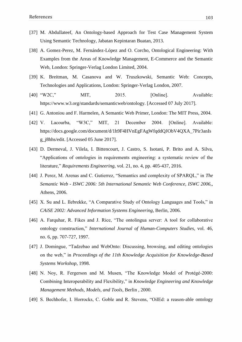
103
References
[37] M. Abdullateef, An Ontology-based Approach for Test Case Management System
Using Semantic Technology, Jabatan Kepintaran Buatan, 2013.
[38] A. Gomez-Perez, M. Fernández-López and O. Corcho, Ontological Engineering: With
Examples from the Areas of Knowledge Management, E-Commerce and the Semantic
Web, London: Springer-Verlag London Limited, 2004.
[39] K. Breitman, M. Casanova and W. Truszkowski, Semantic Web: Concepts,
Technologies and Applications, London: Springer-Verlag London, 2007.
[40] “W2C,” MIT, 2015. [Online]. Available:
https://www.w3.org/standards/semanticweb/ontology. [Accessed 07 July 2017].
[41] G. Antoniou and F. Harmelen, A Semantic Web Primer, London: The MIT Press, 2004.
[42] V. Lacourba, “W3C,” MIT, 21 December 2004. [Online]. Available:
https://docs.google.com/document/d/1h9F4HVnEgFAgWfqddQJObV4QXA_7Pir3anIs
g_j8hhs/edit. [Accessed 05 June 2017].
[43] D. Dermeval, J. Vilela, I. Bittencourt, J. Castro, S. Isotani, P. Brito and A. Silva,
“Applications of ontologies in requirements engineering: a systematic review of the
literature,” Requirements Engineering, vol. 21, no. 4, pp. 405-437, 2016.
[44] J. Perez, M. Arenas and C. Gutierrez, “Semantics and complexity of SPARQL,” in The
Semantic Web - ISWC 2006: 5th International Semantic Web Conference, ISWC 2006,,
Athens, 2006.
[45] X. Su and L. Ilebrekke, “A Comparative Study of Ontology Languages and Tools,” in
CAiSE 2002: Advanced Information Systems Engineering, Berlin, 2006.
[46] A. Farquhar, R. Fikes and J. Rice, “The ontolingua server: A tool for collaborative
ontology construction,” International Journal of Human-Computers Studies, vol. 46,
no. 6, pp. 707-727, 1997.
[47] J. Domingue, “Tadzebao and WebOnto: Discussing, browsing, and editing ontologies
on the web,” in Proceedings of the 11th Knowledge Acquisition for Knowledge-Based
Systems Workshop, 1998.
[48] N. Noy, R. Fergerson and M. Musen, “The Knowledge Model of Protégé-2000:
Combining Interoperability and Flexibility,” in Knowledge Engineering and Knowledge
Management Methods, Models, and Tools, Berlin , 2000.
[49] S. Bechhofer, I. Horrocks, C. Goble and R. Stevens, “OilEd: a reason-able ontology
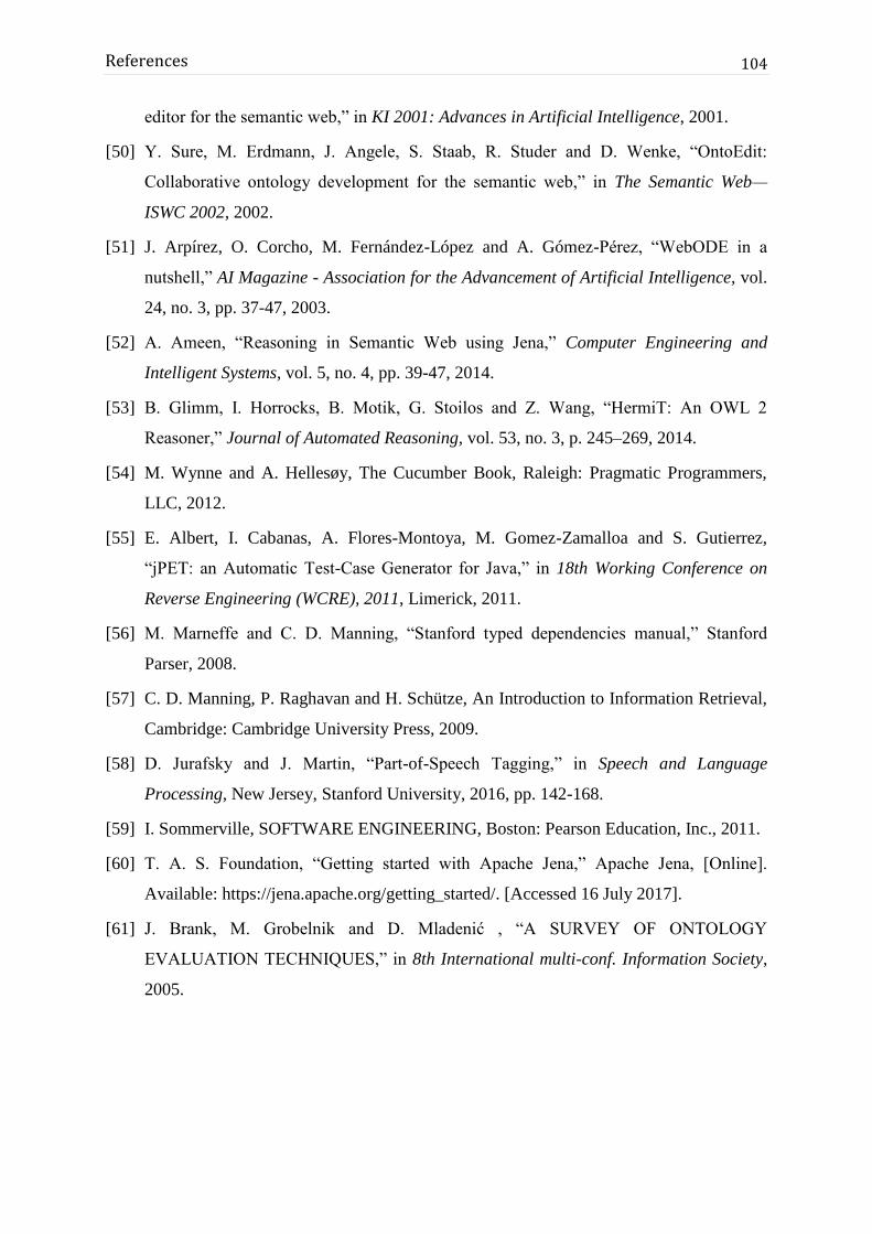
104
References
editor for the semantic web,” in KI 2001: Advances in Artificial Intelligence, 2001.
[50] Y. Sure, M. Erdmann, J. Angele, S. Staab, R. Studer and D. Wenke, “OntoEdit:
Collaborative ontology development for the semantic web,” in The Semantic Web—
ISWC 2002, 2002.
[51] J. Arpírez, O. Corcho, M. Fernández-López and A. Gómez-Pérez, “WebODE in a
nutshell,” AI Magazine - Association for the Advancement of Artificial Intelligence, vol.
24, no. 3, pp. 37-47, 2003.
[52] A. Ameen, “Reasoning in Semantic Web using Jena,” Computer Engineering and
Intelligent Systems, vol. 5, no. 4, pp. 39-47, 2014.
[53] B. Glimm, I. Horrocks, B. Motik, G. Stoilos and Z. Wang, “HermiT: An OWL 2
Reasoner,” Journal of Automated Reasoning, vol. 53, no. 3, p. 245–269, 2014.
[54] M. Wynne and A. Hellesøy, The Cucumber Book, Raleigh: Pragmatic Programmers,
LLC, 2012.
[55] E. Albert, I. Cabanas, A. Flores-Montoya, M. Gomez-Zamalloa and S. Gutierrez,
“jPET: an Automatic Test-Case Generator for Java,” in 18th Working Conference on
Reverse Engineering (WCRE), 2011, Limerick, 2011.
[56] M. Marneffe and C. D. Manning, “Stanford typed dependencies manual,” Stanford
Parser, 2008.
[57] C. D. Manning, P. Raghavan and H. Schütze, An Introduction to Information Retrieval,
Cambridge: Cambridge University Press, 2009.
[58] D. Jurafsky and J. Martin, “Part-of-Speech Tagging,” in Speech and Language
Processing, New Jersey, Stanford University, 2016, pp. 142-168.
[59] I. Sommerville, SOFTWARE ENGINEERING, Boston: Pearson Education, Inc., 2011.
[60] T. A. S. Foundation, “Getting started with Apache Jena,” Apache Jena, [Online].
Available: https://jena.apache.org/getting_started/. [Accessed 16 July 2017].
[61] J. Brank, M. Grobelnik and D. Mladenić , “A SURVEY OF ONTOLOGY
EVALUATION TECHNIQUES,” in 8th International multi-conf. Information Society,
2005.

105
Appendix A – Individual
Contributions
A.1. Name: H.N. Anjalika (2013/CS/009)
According to the background analysis problem of requirement representation and so we got
the chance of applying the Ontology concept into the requirement domain and see the
possibility of automation the test case generation process. Therefore our main research intent
“Ontology based test case generation” was divided into 3 main sub parts as Ontology
identification and implementation, Natural Language Processing techniques to be applied
with user stories and automatic generation of test cases using the Ontology.
As an individual contributor I was assigned for the task of Natural Language Processing
techniques to be applied with user stories. Since our intention was to use user stories as the
initial system input, they were need to process before using to the test case generation.
According to the Ontology model developed, we needed a triplet as actor, action and object
that was extracted from a user story. For this I went through some research papers to get an
idea on how the triplet extraction has been done with respect to extract subject, verb and
object of a sentence. I tried on applying those mentioned algorithms with our user stories
using different approaches and I used Stanford CoreNlp toolkit. My first approach was
following a Stanford Tree parser, but it couldn’t give exact result what I needed. Then I
applied Stanford dependency Parser and by defining a method that matches with the user
stories, I could extract the correct entities up to some extent. There are some future works
need to be considered with this method.
Implementation of the user story form and extracting entities from was done using Spring
MVC framework and hibernate with MySQL database by applying OOP concepts as
necessary. I also involved with designing the architecture and other diagrams while
cooperating to produce various documents of the research. Finally the evaluation process was
done by all 3 of us doing surveys and comparing the system generated results with manual
results taken from sample user stories and test cases.
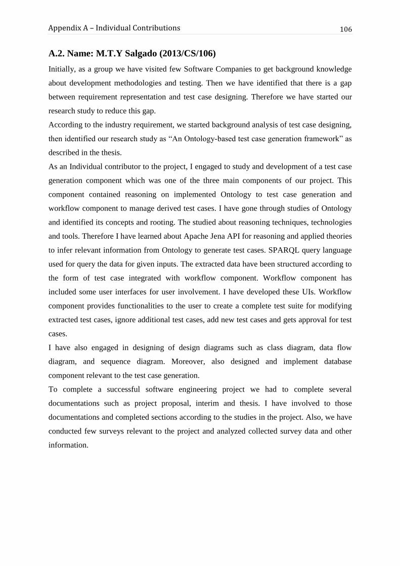
106
Appendix A – Individual Contributions
A.2. Name: M.T.Y Salgado (2013/CS/106)
Initially, as a group we have visited few Software Companies to get background knowledge
about development methodologies and testing. Then we have identified that there is a gap
between requirement representation and test case designing. Therefore we have started our
research study to reduce this gap.
According to the industry requirement, we started background analysis of test case designing,
then identified our research study as “An Ontology-based test case generation framework” as
described in the thesis.
As an Individual contributor to the project, I engaged to study and development of a test case
generation component which was one of the three main components of our project. This
component contained reasoning on implemented Ontology to test case generation and
workflow component to manage derived test cases. I have gone through studies of Ontology
and identified its concepts and rooting. The studied about reasoning techniques, technologies
and tools. Therefore I have learned about Apache Jena API for reasoning and applied theories
to infer relevant information from Ontology to generate test cases. SPARQL query language
used for query the data for given inputs. The extracted data have been structured according to
the form of test case integrated with workflow component. Workflow component has
included some user interfaces for user involvement. I have developed these UIs. Workflow
component provides functionalities to the user to create a complete test suite for modifying
extracted test cases, ignore additional test cases, add new test cases and gets approval for test
cases.
I have also engaged in designing of design diagrams such as class diagram, data flow
diagram, and sequence diagram. Moreover, also designed and implement database
component relevant to the test case generation.
To complete a successful software engineering project we had to complete several
documentations such as project proposal, interim and thesis. I have involved to those
documentations and completed sections according to the studies in the project. Also, we have
conducted few surveys relevant to the project and analyzed collected survey data and other
information.

107
Appendix A – Individual Contributions
A.3. Name: P.I. Siriwardhana (2013/CS/115)
Our project was to research the feasibility of an Ontology to generate test cases and give a
solution to auto generate test cases based on an Ontology using user stories.
To identify the background of this problem, we had few informal discussions with industry
people. At that meetings we discussed about the current industry testing process and
identified the proposed system design. We identified three core components in the proposed
framework as Implement An Ontology, Entity Extraction Using NLP techniques and
Ontology Reasoning and Test case Generation.
My contribution to this work is to research on the feasibility of test case generation based on
an Ontology and to implement a feasible Ontology for software engineering requirement
domain. This was a big challenge to me. Before implement a new Ontology I searched for an
existing Ontology for the required domain. Therefore I contact some researchers who has
done researches on Ontology based test case generation and their idea was also to implement
an Ontology from the scratch due to unavailability of an existing Ontology to develop further.
Implementation of an Ontology was the most challengeable task for me. For that I used
sample user stories and their test cases as the data set and identified a relation between user
stories and test cases. I identified most important words of the user story to write test cases as
user role,his/her functionality and on which object that functionality is performed on.
Therefore I defined that three words as the three concepts of the Ontology and named them as
actor, action and object. According to the sample data set I used object properties which
represent relationships between two classes and two instances, and data properties which
represent data of instances, to set information about them.
Another challenge I faced was to handle similar words of an instances. To overcome that
challenge I created an object property hasSimilarWord and formed a relationship among
those similar instances. To handle the implicit scenarios I created an object property
hasDependancy. To ensure the decision that I have taken, we had some informal discussions
with an Ontology expert.
I contributed for GUI designing, documentations such as Project Proposal, Interim Report,
Thesis and designed the architecture and other diagrams with the help of other two members.
Finally I contributed to collect sample user stories and to evaluate our product results.
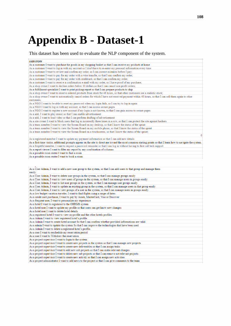
108
Appendix B - Dataset-1 This dataset has been used to evaluate the NLP component of the system.

109
Appendix B – Dataset-1

110
Appendix C - Conducted Surveys
C.1. Survey I
First survey was conducted to gather information about software development and testing
process in current software industry in Sri Lanka. 26 companies have been participated in the
survey and responded.

111
References

112
References

113
References
Below are the responses obtained for some questions from the Survey I.

114
References

115
References

116
References
C.2. Survey II
The second survey was conducted in the evaluation phase to get user evaluation to the
developed system and methodologies. For this survey 5 users have been involved who has
more than one year experience in software testing.

117
References

118
References

119
References
Below are the responses obtained from the Survey II.

120
References

121
References

122
References

123
References

124
References


![Ontology-based Personalised Course Recommendation Framework · 2019. 1. 8. · Ontology-based Personalised Course Recommendation Framework MOHAMMED E. IBRAHIM1,2(Member, ... [25]](https://img.dokumen.tips/doc/110x75/603c6d90a65f9240f444d993/ontology-based-personalised-course-recommendation-framework-2019-1-8-ontology-based.jpg)