Embed Size (px)
Citation preview
Ž .Computers in Industry 39 1999 127–146
An object-oriented rule-based framework for the specification offlexible manufacturing systems
K.L. Mak ), S.T.W. Wong, H.Y.K. LauDepartment of Industrial and Manufacturing Systems Engineering, The UniÕersity of Hong Kong, Pokfulam Road, Hong Kong, China
Received 12 September 1997; accepted 28 September 1998
Abstract
Ž .The design of flexible manufacturing systems FMSs requires an effective system specification method, which is flexibleto cope with redesigns as a result of requirement changes. In order to facilitate the design of such systems, object-orientedmethods are increasingly adopted. However, they only provide limited support to system integration and the explicitspecification of operational policies. In this connection, an object-oriented rule-based specification framework is proposed toincorporate a rule model into an object-oriented specification, to analyze and design the global processes and operationalpolicies of FMSs. The application of this framework is illustrated via the specification of a typical vehicle-based FMS.q 1999 Elsevier Science B.V. All rights reserved.
Keywords: System specification method; Object-oriented; Rule-based; Flexible manufacturing system
1. Introduction
Ž .Flexible manufacturing systems FMSs have beenwidely adopted by modern manufacturers, since theyprovide an efficient means to produce a wide rangeof products having medium to low demand volumes.These systems are characterized by high flexibility inoperation and physical configuration. In this way,minimal production setup time and simultaneousprocessing of various products can be attained insuch systems in a cost effective manner. An FMSgenerally comprises a set of versatile CNC machinesand automatic material handling systems under the
) Corresponding author. Tel.: q852-28592582; fax: q852-28586335; e-mail: [email protected]
control of a supervisory control computer. Due to thehigh degree of integration and complexity, the designof FMSs is a formidable task, and requires expertisein various disciplines. In support of the design andanalysis of FMSs, an effective system specificationmethod is obviously one of the most essential fac-tors, because it can provide a basis for designers tocommunicate with users or other designers, and alsoto evaluate the various design alternatives. For thepurpose of communication and understanding, sys-tem specification methods should generate a highlevel system description, and should support systemanalysis from the viewpoint of users. These methodsshould also contain high flexibility to cope with thechanges in system requirements. This flexibility isespecially essential in the specification of FMSs,because their operation and physical configurationmay change, even during the operation stage.
0166-3615r99r$ - see front matter q 1999 Elsevier Science B.V. All rights reserved.Ž .PII: S0166-3615 98 00141-9
( )K.L. Mak et al.rComputers in Industry 39 1999 127–146128
In order to attain high flexibility in designingwsystems, object-oriented modeling methods 2,12,13,
x17,23 have been applied to the specification ofFMSs. The extensibility, expressiveness, and thepromotion of reusability of object-oriented methodsin modeling manufacturing systems have been articu-
w xlated by different authors, including Adiga 1 , Mengaw x w xet al. 14 and Nof 15 . In FMS designs, object-ori-
ented models are typically used to specify cell con-trollers, control architecture, and simulation softwarew x5,9,10,14,18,20,22 . These models can capture ef-fectively both the behavior of FMS components andalso the control logic for their coordination. In addi-tion, they can streamline the transition from theanalysis stage to the design stage, and also from thedesign stage to the implementation stage.
Although object-oriented methods have beenwidely applied to analyze various areas of manufac-turing systems, significant limitations still exist intheir applications to generate a system specification.One of these limitations concerns system integration.
w xAs noted by various authors 10,16,21 , these meth-ods do not support an integrated view of systembehavior effectively, e.g., the modeling of end-to-endprocesses. Such a limitation stems from the encapsu-lation principle of object-oriented modeling, whichrequires the behavior of an object to be hidden fromother objects. System behavior is therefore specifiedby a set of fragmented message flows and discon-nected behavioral models of individual objects.
The primary focus of most conventional object-oriented modeling methods is on the development ofsoftware systems, rather than on an overall systemdesign. The application of these methods is notadequate to capture the requirements of, for instance,physical processes and configurations of real worldsystems. This is obviously undesirable in the contextof system integration, because the relationships be-tween the control and the physical subsystems can-not be sufficiently reflected in the system specifica-
w xtion. Various authors also pointed out 2,3,16 thatsignificant discrepancies exist between the conven-tional object-oriented models and the ordinary per-ception of real world systems.
A major limitation of these models is the inade-quate representation of real-world events in manufac-turing systems. The use of point-to-point messageflows to abstract system behavior leads to inflexibil-
w xity and over-commitment 2 . In particular, the choiceof ‘objects sending messages’ to represent the occur-rences of real world events in software do not actu-ally align with the perception of users. Indeed, theuse of events rather than messages to specify systembehavior directly has been advocated by some au-
w xthors 2,6,12 . In addition, various extensions to thew xexisting object-oriented models 2,13,16 have also
been proposed to improve the expressiveness to rep-resent real world systems. These extensions not onlyfacilitate the analysis of requirements of softwaresystems, but also allow an integrated design of busi-ness systems containing both software and physical
w xsubsystems. In particular, Martin and Odell 12,13extended the notion of object-oriented modeling forthe representation of concepts about objects. Such anextension allows the system designers’ or users’concepts to be represented in a natural and explicitway.
Apart from the problem of supporting systemintegration, the conventional object-oriented modelsof FMSs also possess limitations in the specificationof operational policies and rules. The operationalpolicies and rules of systems are usually embeddedin the description of procedures, and are not explic-itly specified. As a result, any modification of theserules may lead to undesirable consumption of exces-sive efforts. Since procedural descriptions are gener-ally technical-oriented, and may not be comprehensi-ble to users, a system specification is therefore lim-ited in attaining a good understanding among design-ers and users. In order to enhance the understandabil-ity and flexibility of system specification, the incor-poration of rule-based specifications in the object-oriented models has been proposed by a number ofauthors in the software engineering communityw x4,7,11,19 . Nonetheless, such an incorporation hasnot been noted widely in the existing object-orientedspecification methods for manufacturing systems.
In order to enhance flexibility, and to supportsystem integration at the early stages of design, anobject-oriented rule-based specification frameworkfor the design of an FMS is proposed in this paper.This framework can accommodate the specificationof an FMS through the representation of concepts ofsystem designers by means of an object-orientedapproach. Such a specification allows an integratedview of control and coordination of physical subsys-
( )K.L. Mak et al.rComputers in Industry 39 1999 127–146 129
tems. With the incorporation of rule-based modeling,the framework supports an explicit specification ofoperational and decision rules, such as vehicle dis-patching rules. Object behavior is specified by anaction rule model which is constructed with close
Ž .reference to the event–condition–action ECAw xparadigm 8 . To support an integrated view of object
behavior, a graphical model has also been developedand included in the specification framework. In Sec-tion 2, the basic notions of the object-oriented rule-based modeling and the graphical model will beintroduced.
2. Basic notions
2.1. Object-oriented modeling methods
Object-oriented modeling methods are based onthe notion of objects. In this paper, the definition of
w xobjects given by Martin and Odell 12,13 is adoptedto provide a more general view of objects. Accordingto Martin and Odell, an object can represent anythingin a problem domain, and is an instance of a concept.In this sense, an object is a discrete and distinguish-able unit representing a concrete entity or an abstractconcept in the problem domain. The properties of anobject are described by a set of attributes, of whichthe values may be other objects, numerals or literalvalues. Objects may be used to represent entitieswith behavioral characteristics. In this case, an objectwould be characterized by a number of operationsand states which remember the effect of these opera-tions on the object’s attributes. Hence, an objectpossesses both the structural and behavioral proper-ties.
To put it in the same language adopted by Martinand Odell, a concept is defined as an object type, andthe meanings of an object type are represented by itsassociations with other object types. The definitionof object types and their associations thus provide astructure to represent the concepts of a system designin connection with the various aspects of systems.
In an object-oriented paradigm, a system specifi-cation normally embodies descriptions for the struc-ture and the behavior of object types. The structure isspecified by the associations among the object typesand the constraints applied to the associations,
whereas the behavior is specified by the responses ofthe object types to the occurrences of events. Inorder to generate a meaningful description, the be-havior must be specified within a structure, andbehavioral specifications should thus be based on astructural specification. Since both specifications areexpressed in terms of object types, the description isgeneric in nature, and permits various possible in-stances of implementation. By defining the subtypesof object types, such descriptions can be furtherspecialized to refine the specification of a system, orto incorporate the new features for a similar system.
There are various models and techniques for ob-ject-oriented specification. Among these, graphicalmodels are typically used to express the specifica-tion, due to their advantages in communication andunderstanding. However, these graphical modelsseem to be inefficient in specifying the complexconstraints or relationships among object types. Asan alternative, rule-based models have been em-ployed by various authors to specify the structureand behavior of objects. These models can expressnot only complex logical relationships, but also theoperational rules from the viewpoint of system users.Since rules allow users to specify policies by usingexplicit statements, they facilitate the acquisition ofdomain knowledge in system design. A rule-basedspecification may contain various types of rules.With reference to the classification adopted by
w xLoucopoulos et al. 11 , there are three basic types ofrules, namely, constraint rules, derivation rules andaction rules, which are explained as follows:1. Constraint rules specify the restrictions on object
states.2. DeriÕation rules specify rules to derive facts con-
cerning objects from other facts.3. Action rules specify the behavior of objects in
response to the occurrences of events.These rules are normally textual specifications,
which are well-structured and comprehensible forsystem users. These specifications are commonlyseparated from the graphical specification models. Inorder to provide an alternative method of representa-
w xtion, Martin and Odell 12,13 have demonstrated thepossibility of incorporating the rules into the graphi-cal models. They have also developed a graphicalnotation of action rules, namely, the event diagram,to represent the global system behavior. Such a
( )K.L. Mak et al.rComputers in Industry 39 1999 127–146130
description, however, does not advocate the localiza-tion of the behavioral specification, which is indeedessential to attain the independence of objects. Inaddition, the relationship between the event diagramsand the structural specification of objects is often
w xtenuous 2 . In this connection, a graphical model ofaction rules is proposed in this paper, by drawingclose reference from the ECA paradigm. In spite ofits simplicity in structure, a number of variants existin the ECA rule models.
2.2. ECA rule model
In the proposed rule model, objects are associatedwith a set of properties and operations. The behaviorof objects is depicted by the invocation of opera-tions, which may change the properties and cause theoccurrences of events. The invocation of operationsis specified by a set of action rules. Action rules aredefined on particular object types, so that the behav-ior of each object is governed by the action rulesassociated with its object type. These rules consist ofthree parts, namely, an eÕent part, a condition part,and an action part, and they are structured in thefollowing form:
² :When eÕent-type² :If condition-1, condition-2, condition-3, . . .² :Then action
An action rule specifies an action to be initiatedwhenever an event of a particular type occurs, andthat a set of conditions of the associated objects issatisfied. In comparison with other variants of ECArule models, the proposed rule model contains en-hancements in the modularity and the abstractionmechanism to deal with the complexity of systembehavior. The meanings of the three components ofthe ECA rule and their features are further explainedas follows.
Ž .1 EÕent part. The event part of action rulesspecifies an event type which represents event in-stances. Event types are identified by their names,and are not explicitly associated with any particularcondition of object states or time epochs. Theseevent types can also be specialized into event sub-types, and can allow a refinement of behavioralspecification. Such a refinement is accomplished by
an overriding mechanism, in which an action rulespecified by an event type can be overridden by theaction rules specified by the subtypes of the eventtype.
Ž .2 Condition part. The condition part of actionrules specifies a list of conditions. In order to triggeran action rule, all conditions must be satisfied. Theseconditions refer to a logical assertion of the states ofobject instances. In contrast to the specification ofconditions in other ECA rule models, they are beingconfined to the local states of objects. Such a con-finement can enhance the independence among ob-jects, and hence reduces the effort for any modifica-tion in a behavioral specification.
Ž .3 Action part. The action part of action rulesspecifies an action which may consist of a list ofoperations. Whenever an action rule is triggered byan event, the operations contained in its action willbe initiated sequentially. In contrast to the conven-tional object models, operations are initiated by ac-tion rules rather than by events. These operations canbe contained in various action rules with differentcombinations. Such a reuse of operations in actionrules reduces considerably the complexity in model-ing object behavior.
Since action rules are defined on individual objecttypes, the behavioral specification so derived fromthese rules is rather fragmented. Although the local-ization of the behavioral specification can enhancethe modularity of system design, the success ofsystem integration relies on a global view of thesystem behavior. In order to provide such a globalview to facilitate system integration, a graphicalmodel of action rules, namely, the rule diagram, hasbeen developed to specify object behavior. The nota-tion used in a rule diagram is given in Fig. 1, whichis characterized by the following:Ø It consists of a set of event types and actions
involved in a process.Ø Event types and actions are connected by arrows
symbolizing the causal relationships betweenthem.
Ø Arrows pointing to the event types indicate thatthe actions initiate the occurrence of instances ofthe event types.
Ø Conversely, arrows pointing to actions indicatethat the instances of the event types cause theinvocation of the actions.
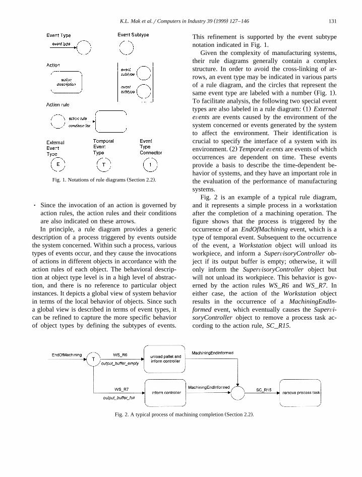
( )K.L. Mak et al.rComputers in Industry 39 1999 127–146 131
Ž .Fig. 1. Notations of rule diagrams Section 2.2 .
Ø Since the invocation of an action is governed byaction rules, the action rules and their conditionsare also indicated on these arrows.In principle, a rule diagram provides a generic
description of a process triggered by events outsidethe system concerned. Within such a process, varioustypes of events occur, and they cause the invocationsof actions in different objects in accordance with theaction rules of each object. The behavioral descrip-tion at object type level is in a high level of abstrac-tion, and there is no reference to particular objectinstances. It depicts a global view of system behaviorin terms of the local behavior of objects. Since sucha global view is described in terms of event types, itcan be refined to capture the more specific behaviorof object types by defining the subtypes of events.
This refinement is supported by the event subtypenotation indicated in Fig. 1.
Given the complexity of manufacturing systems,their rule diagrams generally contain a complexstructure. In order to avoid the cross-linking of ar-rows, an event type may be indicated in various partsof a rule diagram, and the circles that represent the
Ž .same event type are labeled with a number Fig. 1 .To facilitate analysis, the following two special event
Ž .types are also labeled in a rule diagram: 1 ExternaleÕents are events caused by the environment of thesystem concerned or events generated by the systemto affect the environment. Their identification iscrucial to specify the interface of a system with its
Ž .environment. 2 Temporal eÕents are events of whichoccurrences are dependent on time. These eventsprovide a basis to describe the time-dependent be-havior of systems, and they have an important role inthe evaluation of the performance of manufacturingsystems.
Fig. 2 is an example of a typical rule diagram,and it represents a simple process in a workstationafter the completion of a machining operation. Thefigure shows that the process is triggered by theoccurrence of an EndOfMachining event, which is atype of temporal event. Subsequent to the occurrenceof the event, a Workstation object will unload itsworkpiece, and inform a SuperÕisoryController ob-ject if its output buffer is empty; otherwise, it willonly inform the SuperÕisoryController object butwill not unload its workpiece. This behavior is gov-erned by the action rules WS_R6 and WS_R7. Ineither case, the action of the Workstation objectresults in the occurrence of a MachiningEndIn-formed event, which eventually causes the SuperÕi-soryController object to remove a process task ac-cording to the action rule, SC_R15.
Ž .Fig. 2. A typical process of machining completion Section 2.2 .
( )K.L. Mak et al.rComputers in Industry 39 1999 127–146132
3. Modeling framework
In the proposed object-oriented rule-based specifi-cation framework, systems are specified at two mod-eling levels, namely, the structure leÕel and theknowledge leÕel. At the structural modeling level,systems are described from the viewpoint of theircomposition and organization. According to such adescription, entities that perform the specific func-tions to attain the predetermined objectives are speci-fied. These entities may include machines, materials,computers, people, or application programs, and theyare defined as functional entities in this paper. Thefunctional entities commonly depict behavior, whichcan be described in terms of the responses to realworld events. These functional entities can be furtherdivided into control entities and operational entities,to reflect the coordinated nature of behavior of man-ufacturing systems. In this vein, the operational enti-ties perform activities to realize system functions,while the control entities are responsible for control-ling these activities to attain certain objectives.
In order to realize control functions, control enti-ties requires various kinds of information and knowl-edge which may include the states of operationalentities, operational policies, and decision rules. Suchrequirements are reflected by the information entitiesin a system. These informational entities may refer todata structures in the application programs, databases or knowledge bases. At the knowledge level of
system modeling, systems are described by referringto these entities. Such a description allows systemdesigners to analyze information, operational con-straints, and decision rules in a system.
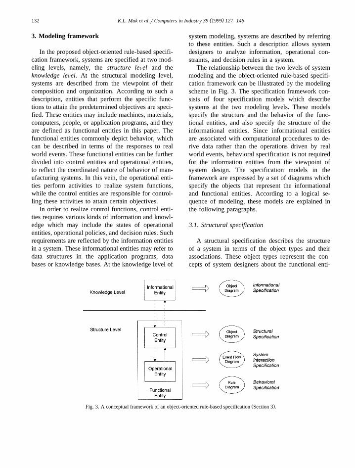
The relationship between the two levels of systemmodeling and the object-oriented rule-based specifi-cation framework can be illustrated by the modelingscheme in Fig. 3. The specification framework con-sists of four specification models which describesystems at the two modeling levels. These modelsspecify the structure and the behavior of the func-tional entities, and also specify the structure of theinformational entities. Since informational entitiesare associated with computational procedures to de-rive data rather than the operations driven by realworld events, behavioral specification is not requiredfor the information entities from the viewpoint ofsystem design. The specification models in theframework are expressed by a set of diagrams whichspecify the objects that represent the informationaland functional entities. According to a logical se-quence of modeling, these models are explained inthe following paragraphs.
3.1. Structural specification
A structural specification describes the structureof a system in terms of the object types and theirassociations. These object types represent the con-cepts of system designers about the functional enti-
Ž .Fig. 3. A conceptual framework of an object-oriented rule-based specification Section 3 .
( )K.L. Mak et al.rComputers in Industry 39 1999 127–146 133
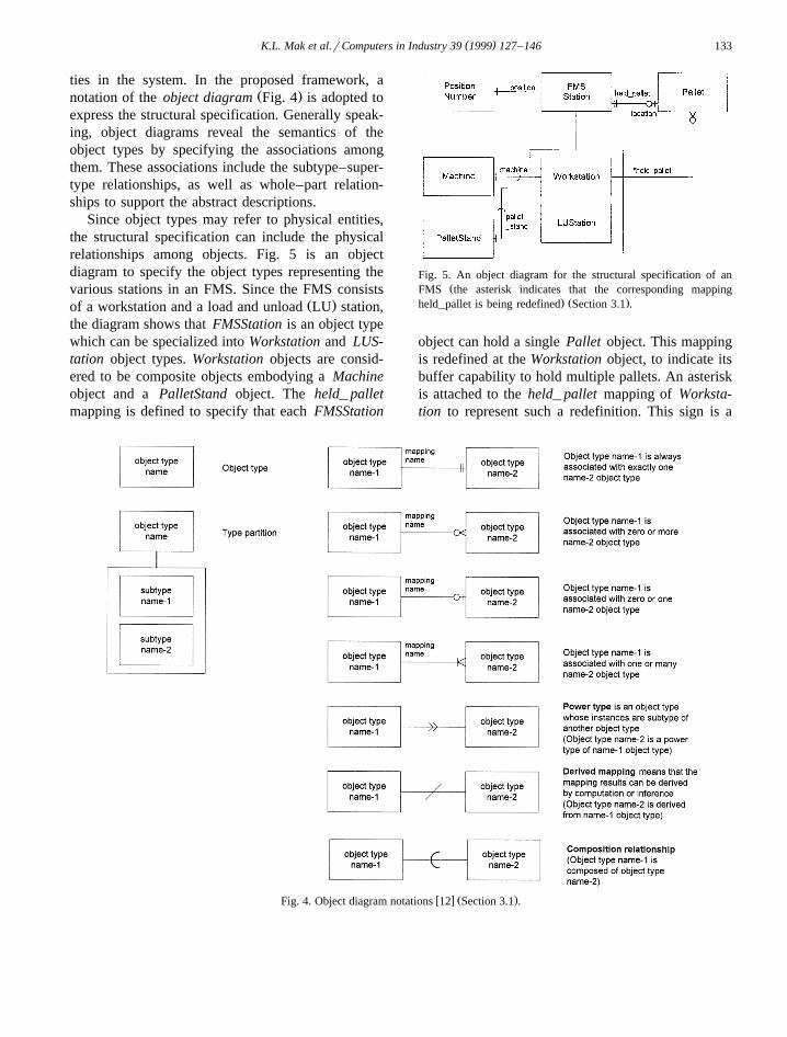
ties in the system. In the proposed framework, aŽ .notation of the object diagram Fig. 4 is adopted to
express the structural specification. Generally speak-ing, object diagrams reveal the semantics of theobject types by specifying the associations amongthem. These associations include the subtype–super-type relationships, as well as whole–part relation-ships to support the abstract descriptions.
Since object types may refer to physical entities,the structural specification can include the physicalrelationships among objects. Fig. 5 is an objectdiagram to specify the object types representing thevarious stations in an FMS. Since the FMS consists
Ž .of a workstation and a load and unload LU station,the diagram shows that FMSStation is an object typewhich can be specialized into Workstation and LUS-tation object types. Workstation objects are consid-ered to be composite objects embodying a Machineobject and a PalletStand object. The held_ palletmapping is defined to specify that each FMSStation
Fig. 5. An object diagram for the structural specification of anŽFMS the asterisk indicates that the corresponding mapping
. Ž .held_pallet is being redefined Section 3.1 .
object can hold a single Pallet object. This mappingis redefined at the Workstation object, to indicate itsbuffer capability to hold multiple pallets. An asteriskis attached to the held_ pallet mapping of Worksta-tion to represent such a redefinition. This sign is a
w x Ž .Fig. 4. Object diagram notations 12 Section 3.1 .
( )K.L. Mak et al.rComputers in Industry 39 1999 127–146134
new notation which is added to the object diagram toindicate the redefinition of mappings.
As spatial configuration is important for the de-sign of FMSs, the PositionNumber is defined tocapture the spatial property of FMSStation. Unlikethe other object types, PositionNumber does notrefer to any physical entities, and it is an abstractobject type defined for the purpose of understanding.The instances of the PositionNumber may be repre-sented by different types of numbers.
3.2. Informational specification
While a structural specification describes the sys-tem structure from an organizational perspective, aninformational specification describes the systemstructure from an operational perspective. Neverthe-less, an informational specification resembles a struc-tural specification in that it is also expressed withobject diagrams. These diagrams specify the objectsthat represent the information entities and their rela-tionships. With reference to these diagrams, the sys-tem designers can express data structures and deci-sion rules for system control. Since data structuresfor system control normally contain entities corre-sponding to the physical entities in a structural speci-fication, a convention of adding a ‘D’ in front of theidentities of object types in an informational specifi-cation is adopted to avoid confusion.
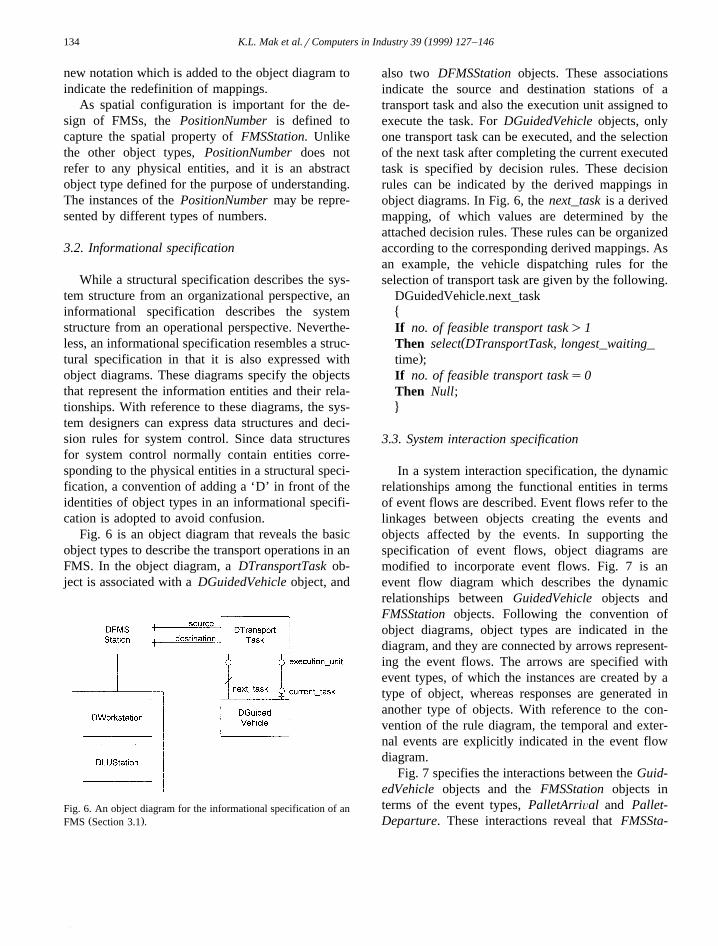
Fig. 6 is an object diagram that reveals the basicobject types to describe the transport operations in anFMS. In the object diagram, a DTransportTask ob-ject is associated with a DGuidedVehicle object, and
Fig. 6. An object diagram for the informational specification of anŽ .FMS Section 3.1 .
also two DFMSStation objects. These associationsindicate the source and destination stations of atransport task and also the execution unit assigned toexecute the task. For DGuidedVehicle objects, onlyone transport task can be executed, and the selectionof the next task after completing the current executedtask is specified by decision rules. These decisionrules can be indicated by the derived mappings inobject diagrams. In Fig. 6, the next_task is a derivedmapping, of which values are determined by theattached decision rules. These rules can be organizedaccording to the corresponding derived mappings. Asan example, the vehicle dispatching rules for theselection of transport task are given by the following.
DGuidedVehicle.next_task�If no. of feasible transport task)1
(Then select DTransportTask, longest_waiting_.time ;
If no. of feasible transport tasks0Then Null;4
3.3. System interaction specification
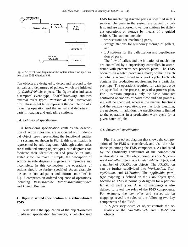
In a system interaction specification, the dynamicrelationships among the functional entities in termsof event flows are described. Event flows refer to thelinkages between objects creating the events andobjects affected by the events. In supporting thespecification of event flows, object diagrams aremodified to incorporate event flows. Fig. 7 is anevent flow diagram which describes the dynamicrelationships between GuidedVehicle objects andFMSStation objects. Following the convention ofobject diagrams, object types are indicated in thediagram, and they are connected by arrows represent-ing the event flows. The arrows are specified withevent types, of which the instances are created by atype of object, whereas responses are generated inanother type of objects. With reference to the con-vention of the rule diagram, the temporal and exter-nal events are explicitly indicated in the event flowdiagram.
Fig. 7 specifies the interactions between the Guid-edVehicle objects and the FMSStation objects interms of the event types, PalletArriÕal and Pallet-Departure. These interactions reveal that FMSSta-
( )K.L. Mak et al.rComputers in Industry 39 1999 127–146 135
Fig. 7. An event flow diagram for the system interaction specifica-Ž .tion of an FMS Section 3.3 .
tion objects are designed to detect and respond to thearrivals and departures of pallets, which are initiatedby GuidedVehicle objects. The figure also indicatesa temporal event type, EndOf TraÕelling, and twoexternal event types, PartArriÕal and PartDepar-ture. These event types represent the completion of atravelling operation and the arrival and departure ofparts in loading and unloading stations.
3.4. BehaÕioral specification
A behavioral specification contains the descrip-tion of action rules that are associated with individ-ual object types representing the functional entitiesin a system. As shown in Fig. 2, this specification isrepresented by rule diagrams. Although action rulesare distributed among object types, rule diagrams canfacilitate their identification and provide an inte-grated view. To make it simple, the description ofactions in rule diagrams is generally imprecise andincomplete. In this connection, the operations ofactions should be further specified. As an example,the action ‘unload pallet and inform controller’ inFig. 2 comprises an ordered sequence of operations,including ResetMachine, InformMachiningEndedand UnloadMachine.
4. Object-oriented specification of a vehicle-basedFMS
To illustrate the application of the object-orientedrule-based specification framework, a vehicle-based
FMS for machining discrete parts is specified in thissection. The parts in the system are carried by pal-lets, and are transported to various stations for differ-ent operations or storage by means of a guidedvehicle. The stations include:Ø workstations for machining parts,Ø storage stations for temporary storage of pallets,
andØ LU stations for the palletization and depalletiza-
tion of parts.The flow of pallets and the initiation of machining
are controlled by a supervisory controller, in accor-dance with predetermined process plans. The FMSoperates on a batch processing mode, so that a batchof jobs is accomplished in a work cycle. Each jobcontains the production requirement for a particularpart type. The operations required for each part typeare specified in the process steps of a process plan.For illustration purposes, only the basic computercontrolled operations of pallet flow and part process-ing will be specified, whereas the manual functionsand the auxiliary operations, such as tools handling,are neglected. In addition, the specification is limitedto the operations in a production work cycle for agiven batch of jobs.
4.1. Structural specification
Fig. 8 is an object diagram that shows the compo-sition of the FMS so considered, and also the rela-tionships among the FMS components. As indicatedby the cardinality constraints of the compositionrelationships, an FMS object comprises one SuperÕi-soryController object, one GuidedVehicle object, anda number of FMSStation objects. The FMSStationcan be further subdivided into Workstation, Stor-ageStation, and LUStation. The applicable_ part_type mapping is defined on the FMS object type,because an FMS is normally designed for a particu-lar set of part types. A set of mappings is alsodefined to reveal the roles of the FMS components.For example, the controller and serÕed_stationmappings reveal the roles of the following two keycomponents of the FMS:Ø A SuperÕisoryController object controls the ac-
tivities of the GuidedVehicle and FMSStationobjects

( )K.L. Mak et al.rComputers in Industry 39 1999 127–146136
Ž .Fig. 8. Structural specification of the FMS Section 4.1 .
Ø A GuidedVehicle object serves to transfer Palletobjects among the FMSStation objects.Due to the cardinality constraint of the held_ pal-
let, a GuidedVehicle or FMSStation object can onlyhold one single Pallet object. Such a constraint is,however, overridden in Workstation objects, whichcontain input buffers and output buffers. In consider-ing the physical structure of the FMS, the Position-Number is defined to specify the physical position ofthe GuidedVehicle and FMSStation objects. As forPallet objects, the position can be indirectly indi-cated by the location mapping, which may refer to aGuidedVehicle or FMSStation object.
4.2. Informational specification
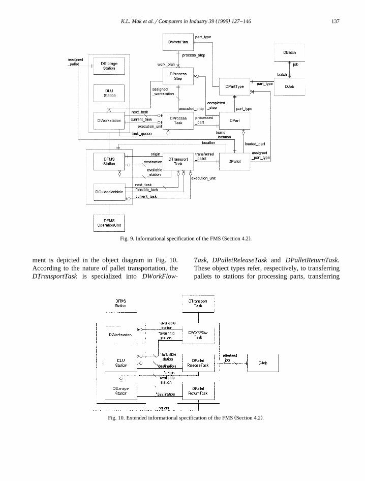
Fig. 9 is an object diagram which expresses theinformational specification of the FMS, with objecttypes representing the informational entities requiredfor supervisory controllers to execute their controlfunctions. Three groups of object types can be identi-fied in the diagram.
Ž .1 The object types corresponding to the physicalcomponents of the FMS. These include the
DFMSStation, DGuidedVehicle, DPallet and DPart.Similar to the structural specification, the DFMSSta-tion is specialized into three object types, namely,DWorkstation, DStorageStation and DLUStation. InFig. 9, the mappings of DPallet indicate that a palletcan only be loaded with a part, and it has a locationdefined by the FMS stations. The mappings alsospecify a system configuration that each pallet isassigned to a unique part type, and has a homelocation in a storage station.
Ž .2 The object types corresponding to the plan-ning data that is used to direct the operations in theFMS. These include DBatch, DJob, DPartType,DProcessPlan and DProcessStep. The associationsamong these object types reveal that a batch containsa number of jobs for various part types, and eachpart type is associated with a process plan specifyinga sequence of process steps. In addition, the routingflexibility is reflected in the multiplicity of the as-signed_workstation mapping.
Ž .3 The object types corresponding to the processand transport tasks. The former refers to the process-ing of a part in a workstation for a process step,whereas the latter refers to the transportation of apallet from one station to another station by meansof a guided vehicle. These tasks provide a basis forthe coordination of physical operations within anFMS. In this study, they are represented by DPro-cessTask and DTransportTask.
According to the definition of process task, aDProcessTask object is associated with a DPartobject, a DProcessStep object and a DWorkstationobject. Since workstations contain local buffers, eachDWorkstation object may have a queue of processtasks during its operation. Thus, the next_task, cur-rent_task, and task_queue mappings of the DWork-station are defined to describe this situation. Simi-larly, DTransportTask is associated with DFMSSta-tion, DPallet and DGuidedVehicle. Since the trans-portation of pallets may be blocked in destinationstations, transport tasks may not be feasible. Toindicate the feasibility of transport tasks, a feasi-ble_task mapping is defined in the DGuidedVehicle.
By working on the object-oriented principle, theinformational specification can be extended to incor-porate refined descriptions. In particular, theDTransportTask can be refined to capture the moredetailed characteristics of pallet flow. Such a refine-
( )K.L. Mak et al.rComputers in Industry 39 1999 127–146 137
Ž .Fig. 9. Informational specification of the FMS Section 4.2 .
ment is depicted in the object diagram in Fig. 10.According to the nature of pallet transportation, theDTransportTask is specialized into DWorkFlow-
Task, DPalletReleaseTask and DPalletReturnTask.These object types refer, respectively, to transferringpallets to stations for processing parts, transferring
Ž .Fig. 10. Extended informational specification of the FMS Section 4.2 .
( )K.L. Mak et al.rComputers in Industry 39 1999 127–146138
empty pallet from storage stations to LU stations forpalletizing and releasing parts into systems, andtransferring empty pallets from LU stations to stor-age stations after depalletizing parts.
These specialized transport tasks still conform tothe specification presented in Fig. 9, except thatsome mappings are redefined to reflect the morespecific characteristics. For instance, the aÕailable_station mappings are redefined to refer to the morespecific subtypes of DFMSStation. The released_ jobmapping is defined on the DPalletReleaseTask, be-cause the released pallet tasks represent the releaseof production jobs, and their execution depends onthe priorities of jobs. The refinement of the transporttasks provides a basis for the formulation of dis-patching rules.
With reference to the associations between thetasks and other entities, the operational policies, suchas vehicle dispatching rules, can also be identified.Indeed, the next_task mapping of the DWorkstationis a derived mapping determined by a decision rule,to select a desired process task from the task queueof the corresponding workstation. Similarly, a dis-patching rule is required to determine the next_taskof the DGuidedVehicle.
In view of the possibility of blocking, the selec-tion of the transport tasks is limited to the values offeasible_task, where the destination station is not
blocked. To reflect the flexibility of material flow,the destination of DTransportTask is defined as aderived mapping, so that the destination station oftransport tasks is dictated by the decision rules basedon a dynamic status. The decision rules for thedetermination of the destination station and the nexttransport task of the guided vehicle are listed inAppendix A. Since the selection of destinations oftransport tasks depends on the type of tasks, thedecision rules are designed for individual types oftasks.
4.3. System interaction specification
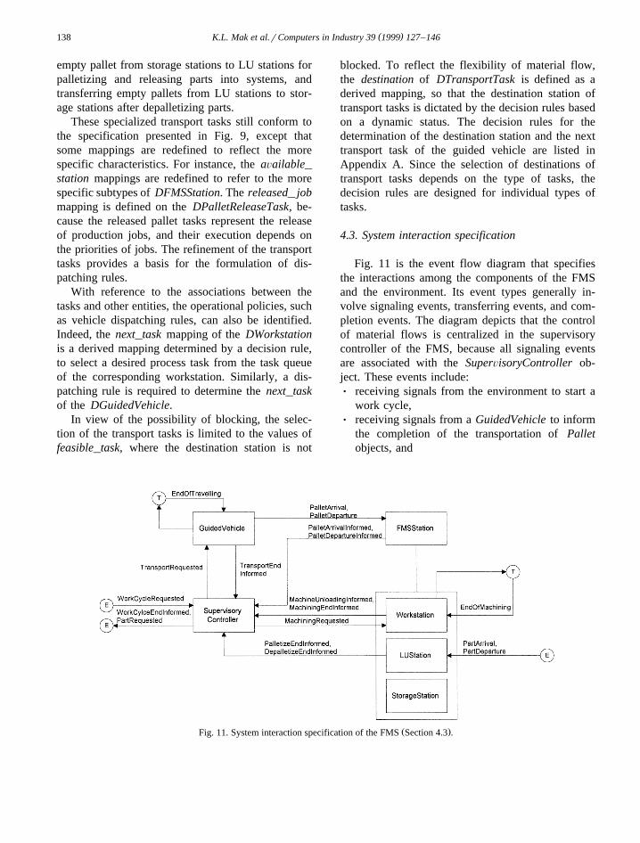
Fig. 11 is the event flow diagram that specifiesthe interactions among the components of the FMSand the environment. Its event types generally in-volve signaling events, transferring events, and com-pletion events. The diagram depicts that the controlof material flows is centralized in the supervisorycontroller of the FMS, because all signaling eventsare associated with the SuperÕisoryController ob-ject. These events include:Ø receiving signals from the environment to start a
work cycle,Ø receiving signals from a GuidedVehicle to inform
the completion of the transportation of Palletobjects, and
Ž .Fig. 11. System interaction specification of the FMS Section 4.3 .
( )K.L. Mak et al.rComputers in Industry 39 1999 127–146 139
Ø receiving signals from FMSStation objects to in-form the arrival or departure of Pallet objects.In response to these events, the SuperÕisoryCon-
troller object may have the following reactions:Ø signals to the GuidedVehicle objects to request
the transportation of Pallet objects,Ø signals to Workstation objects to request the ma-
chining of Part objects, andØ signals to the environment to request the input of
Part objects and to inform the completion of awork cycle.
Ž .As in the structural specification Fig. 8 , theFMSStation is specialized into three subtypes tospecify the more specific interactions between theSuperÕisoryController object and the FMSStationobjects. These specific interactions include sendingsignals from LUStation objects to inform the com-pletion of palletization or depalletization, and send-ing signals from the Workstation objects to informthe completion of machining Part objects or unload-ing of Pallet objects. Apart from the signaling events,there are also events of transferring the physicalentities among components of the FMS. Fig. 11shows that these events include transferring the Pal-let objects between a GuidedVehicle object and aFMSStation object, as well as transferring Part ob-jects between LUStation objects and the environ-ment. These transferring events can reflect the re-quirements of material handling for the FMS sta-tions.
As a physical system, an FMS involves physicaloperations which requires a significant amount oftime to accomplish. There are two completion eventtypes specified in Fig. 5 to reflect such time-depen-dent behavior, and they are EndOf TraÕelling andEndOf Machining, which represent, respectively, thecompletion of transporting Pallet objects and ma-chining of Part objects.
4.4. BehaÕioral specification
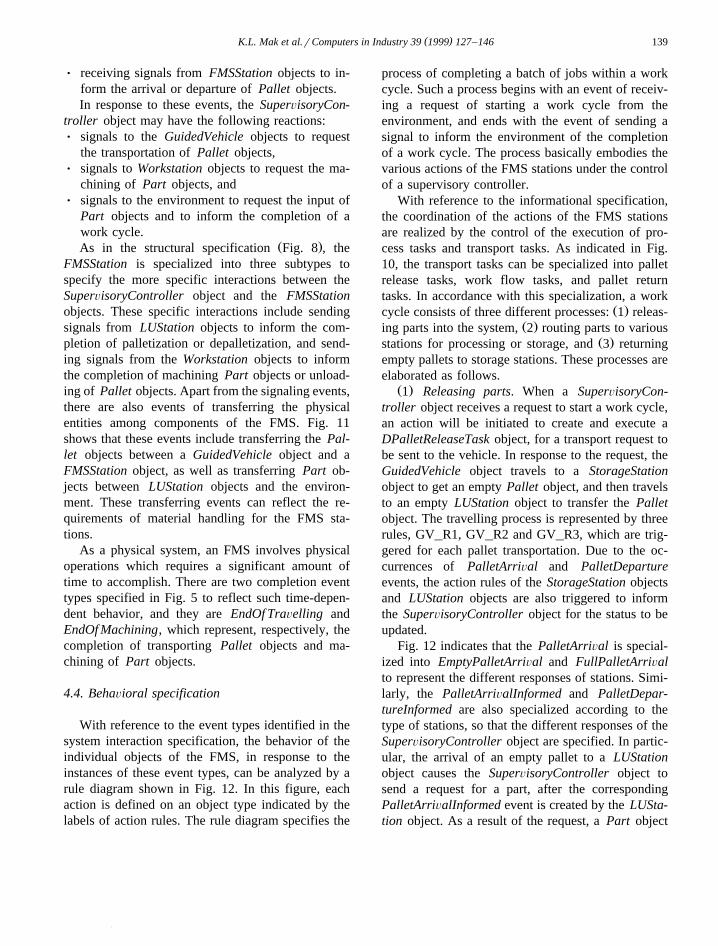
With reference to the event types identified in thesystem interaction specification, the behavior of theindividual objects of the FMS, in response to theinstances of these event types, can be analyzed by arule diagram shown in Fig. 12. In this figure, eachaction is defined on an object type indicated by thelabels of action rules. The rule diagram specifies the
process of completing a batch of jobs within a workcycle. Such a process begins with an event of receiv-ing a request of starting a work cycle from theenvironment, and ends with the event of sending asignal to inform the environment of the completionof a work cycle. The process basically embodies thevarious actions of the FMS stations under the controlof a supervisory controller.
With reference to the informational specification,the coordination of the actions of the FMS stationsare realized by the control of the execution of pro-cess tasks and transport tasks. As indicated in Fig.10, the transport tasks can be specialized into palletrelease tasks, work flow tasks, and pallet returntasks. In accordance with this specialization, a work
Ž .cycle consists of three different processes: 1 releas-Ž .ing parts into the system, 2 routing parts to various
Ž .stations for processing or storage, and 3 returningempty pallets to storage stations. These processes areelaborated as follows.
Ž .1 Releasing parts. When a SuperÕisoryCon-troller object receives a request to start a work cycle,an action will be initiated to create and execute aDPalletReleaseTask object, for a transport request tobe sent to the vehicle. In response to the request, theGuidedVehicle object travels to a StorageStationobject to get an empty Pallet object, and then travelsto an empty LUStation object to transfer the Palletobject. The travelling process is represented by threerules, GV_R1, GV_R2 and GV_R3, which are trig-gered for each pallet transportation. Due to the oc-currences of PalletArriÕal and PalletDepartureevents, the action rules of the StorageStation objectsand LUStation objects are also triggered to informthe SuperÕisoryController object for the status to beupdated.
Fig. 12 indicates that the PalletArriÕal is special-ized into EmptyPalletArriÕal and FullPalletArriÕalto represent the different responses of stations. Simi-larly, the PalletArriÕalInformed and PalletDepar-tureInformed are also specialized according to thetype of stations, so that the different responses of theSuperÕisoryController object are specified. In partic-ular, the arrival of an empty pallet to a LUStationobject causes the SuperÕisoryController object tosend a request for a part, after the correspondingPalletArriÕalInformed event is created by the LUSta-tion object. As a result of the request, a Part object

()
K.L
.Mak
etal.r
Com
putersin
Industry39
1999127
–146
140
Ž .Fig. 12. Behavioral specification of the FMS Section 4.4 .
( )K.L. Mak et al.rComputers in Industry 39 1999 127–146 141
from the environment will arrive and be palletized atthe LUStation object.
After the SuperÕisoryController object is in-formed by the LUStation object for the completionof palletization, a DWorkFlowTask object will becreated to transfer the part to workstations, and therelease process is completed. Whenever a Palletobject departs from a LUStation object, a DPal-letReleaseTask object will be created for other unre-leased DJob objects, and its execution repeats therelease process again.
Ž .2 Routing parts. Part objects are carried byPallet objects, and are routed to Workstation objectsaccording to the specification in DProcessPlan ob-jects. After the arrival of a full Pallet object at aWorkstation object, the SuperÕisoryController ob-ject will be informed, and a DProcessTask objectwill be created. If the Workstation object is idle, theDProcessTask object will be executed, and theWorkstation object will receive a machining request.The request causes the Workstation object to load thePallet object from its input buffer and to start ma-chining operation.
When machining is completed, the Pallet objectwill be unloaded if the output buffer of the Worksta-tion object is empty, and the SuperÕisoryControllerobject will be informed of the completion of theprocess task and the unloading of the Pallet object.Upon receiving the signal for unloading, the Super-ÕisoryController object can have various responses,depending on the existence of waiting tasks, and alsothe availability of the GuidedVehicle object as indi-cated by SC_R11, SC_R12, SC_R13 and SC_R14.These responses commonly result in the creation of aDWorkFlowTask for routing the Pallet object toother FMSStation objects. In particular, a DWork-FlowTask will be created for routing the Palletobject to a LUStation object for depalletization,when all the machining operations in the Workstationobjects are completed.
Ž .3 Returning empty pallets. After the completionof the machining operations in the Workstation ob-jects, a full Pallet object is transferred to a LUSta-tion object, and an action of depalletization andinforming the SuperÕisoryController object will betriggered in the LUStation object. After the depal-letization, the SuperÕisoryController object will beinformed, and a DPalletReturnTask object will be
created to transfer the empty Pallet object back to itshome StorageStation object. If all jobs are com-pleted, a signal will be sent to the higher levelcontrol system to inform the end of a work cycle.
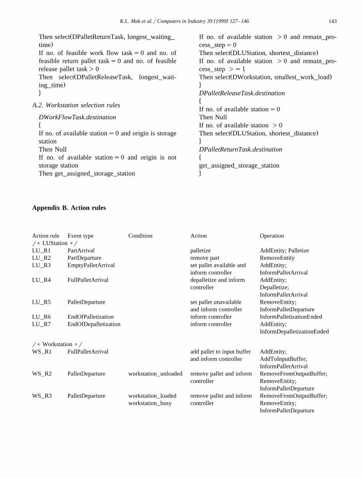
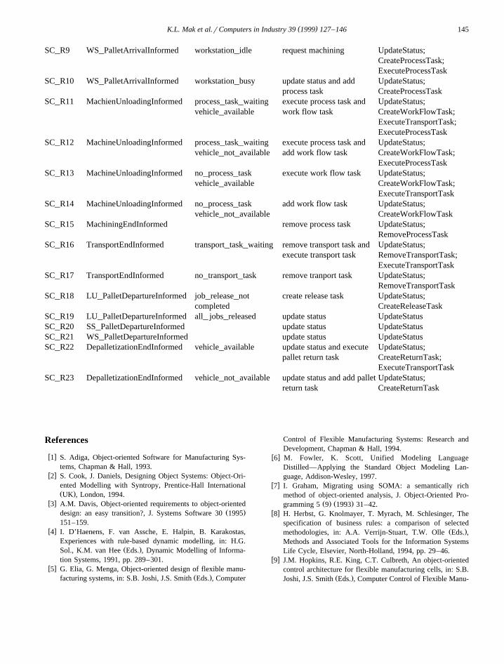
The rule diagram can lead to the identification ofthe action rules of individual object types. Theseaction rules are grouped by the corresponding objecttypes, and are tabulated in Appendix B. The actionsof these rules are further specified by sequences ofoperations. These action rules and operations providea basis to analyze the behavior of individual objecttypes, which is essential to the subsequent realizationof the system.
5. Conclusion
An object-oriented rule-based specification frame-work has been presented in this paper to support thedesign of an FMS by means of an object-orientedapproach. This framework provides an integratedview of the overall control and interaction of thephysical subsystems, thus allowing the analysis ofsystem integration problems in an early design stage.With the incorporation of a rule-based specification,the decision rules and the operational rules can beexplicitly specified and modified conveniently.
The application of the framework is illustrated bythe specification of a typical vehicle-based FMS inthis paper. In this specification, the concepts about asupervisory controller, a guided vehicle, and theother FMS stations are represented in the same ob-ject model. By adopting the proposed rule diagram, apart production in an FMS is considered to be anintegrated process involving the operations of super-visory controllers, FMS workstations, and guidedvehicles. Such an integrated model facilitates theanalysis of system integration issues, and also pro-vides a common model for subsequent detailed de-sign and implementation. These issues can involveboth software design and mechanical design.
At the knowledge modeling level, the operationalknowledge used to control the FMS is captured in aninformational specification. This specification notonly defines the requirements for information, butalso helps system designers to identify decisionpoints, and to specify the operational policies. Hence,decision rules, such as vehicle dispatching rules, can
( )K.L. Mak et al.rComputers in Industry 39 1999 127–146142
be explicitly incorporated into an object model of theFMS. Such an incorporation reduces the efforts inmodifying the operational policies during the specifi-cation stage. It also enhances the understandingamong system users and designers in the coordinatedbehavior of the FMS.
The proposed framework offers an invaluablemeans for system designers to specify the complexstructure and behavior of an FMS. In order to avoidfinancial losses due to inconsistency or incomplete-ness, the correctness of this specification must beverified before proceeding to subsequent system de-velopment stages. The present study also considersthe problems of deadlock and other behaviours, suchas synchronization, and resource conflicts for dy-namic systems. In this connection, this research hasalso focused on developing a framework to verifythe correct behavior of the specification generatedthrough prototyping. A frame-based prototyping ap-proach has been developed recently by the authors toverify system specifications prior to their subsequentrealization. A prototyping tool has also been devel-oped to provide an environment to build and analysethe prototypes, and also to support and streamlinethis approach. The tool provides a set of genericclasses and instances for the construction, execution,and verification of prototypes. These generic classesrepresent the semantic elements, such as the actionrules found in behavior specifications, and enable adirect mapping of the system specifications onto thesubclasses of these generic classes. This tool enablesthe behavior of a system environment to be definedwith the appropriate action rules, and the behavior ofthe system can be checked against its original re-quirement with an accurate ‘simulation’, accordingto the system environment that was defined. The
Ž .approach contains two distinct features: 1 both theŽsystem specifications such as the behavioral specifi-
.cation depicted in Fig. 12 and the prototypes arecommonly derived from an object-oriented model of
Ž .the final system. 2 The frame-based representationmethod is applied to build the prototypes, so that thesemantic information in the specification of the dif-ferent aspects of systems can be directly mappedonto a prototype.
In fact, other methods and approaches can alsofacilitate the study of the dynamics of the interactingsystems. These analytical approaches may be used
during system design to ensure that a complex sys-tem is free from deadlocks and other undesirablebehaviors. Among these approaches, Petri nets aresuitable to represent complex interactions, such asprecedence relations, concurrence, and synchroniza-tion in FMSs. Petri nets can be used to compute
Ž .reachability graphs RGs to analyze the possiblesequences of activities that will lead to the comple-tion of tasks. For example, a deadlock free systemshould contain at least one feasible path in thereachable graph of a system. As regards the presentstudy, a reachability graph can be constructed, andthe enumeration of all the feasible paths can deducethe correctness of behavior. In addition, the systemshown by Fig. 12 does not specify any constraint inresources, and this reduces the chance of the occur-rence of deadlocks.
The use of formal mathematics to analyze processdynamics is another powerful method to ensure thecorrect behaviour of a system. In particular, theformal method of Communicating Sequential Pro-
Ž .cesses CSP is suitable for the modeling and thereasoning with the interacting subsystems, in termsof their concurrence and synchronization. Each inter-acting subsystem can be specified in the language ofCSP, and can be manipulated under the defined rulesand axioms, so that the overall system behavior canbe derived.
Acknowledgements
The authors wish to thank the referees for theirconstructive comments and suggestions about theearlier version of this paper.
Appendix A. Derivation rules
A.1. Vehicle dispatching rules
DGuidedVehicle.next_task�If no. of feasible work flow task)0
ŽThen select DWorkflowTask, longest_waiting_.time
If no. of feasible work flow tasks0 and no. offeasible return pallet task)0
( )K.L. Mak et al.rComputers in Industry 39 1999 127–146 143
ŽThen select DPalletReturnTask, longest_waiting_.time
If no. of feasible work flow tasks0 and no. offeasible return pallet tasks0 and no. of feasiblerelease pallet task)0
ŽThen select DPalletReleaseTask, longest_wait-.ing_time
4
A.2. Workstation selection rules
DWorkFlowTask.destination�If no. of available stations0 and origin is storagestationThen NullIf no. of available stations0 and origin is notstorage stationThen get_assigned_storage_station
If no. of available station )0 and remain_pro-cess_steps0
Ž .Then select DLUStation, shortest_distanceIf no. of available station )0 and remain_pro-cess_step )s1
Ž .Then select DWorkstation, smallest_work_load4DPalletReleaseTask.destination�If no. of available stations0Then NullIf no. of available station )0
Ž .Then select DLUStation, shortest_distance4DPalletReturnTask.destination�get_assigned_storage_station4
Appendix B. Action rules
Action rule Event type Condition Action Operationr) LUStation )rLU_R1 PartArrival palletize AddEntity; PalletizeLU_R2 PartDeparture remove part RemoveEntityLU_R3 EmptyPalletArrival set pallet available and AddEntity;
inform controller InformPalletArrivalLU_R4 FullPalletArrival depalletize and inform AddEntity;
controller Depalletize;InformPalletArrival
LU_R5 PalletDeparture set pallet unavailable RemoveEntity;and inform controller InformPalletDeparture
LU_R6 EndOfPalletization inform controller InformPalletizationEndedLU_R7 EndOfDepalletization inform controller AddEntity;
InformDepalletizationEnded
r) Workstation )rWS_R1 FullPalletArrival add pallet to input buffer AddEntity;
and inform controller AddToInputBuffer;InformPalletArrival
WS_R2 PalletDeparture workstation_unloaded remove pallet and inform RemoveFromOutputBuffer;controller RemoveEntity;
InformPalletDepartureWS_R3 PalletDeparture workstation_loaded remove pallet and inform RemoveFromOutputBuffer;
workstation_busy controller RemoveEntity;InformPalletDeparture
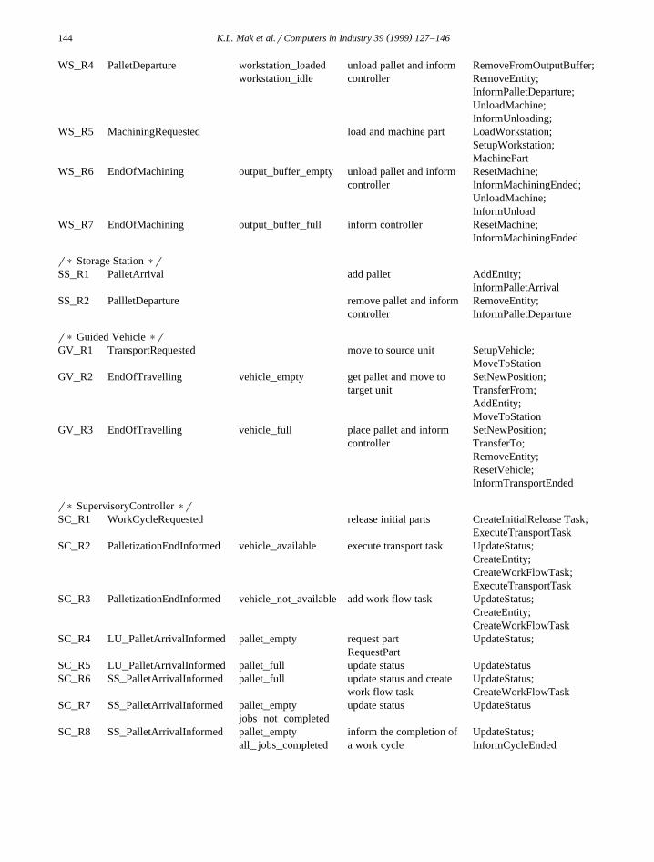
( )K.L. Mak et al.rComputers in Industry 39 1999 127–146144
WS_R4 PalletDeparture workstation_loaded unload pallet and inform RemoveFromOutputBuffer;workstation_idle controller RemoveEntity;
InformPalletDeparture;UnloadMachine;InformUnloading;
WS_R5 MachiningRequested load and machine part LoadWorkstation;SetupWorkstation;MachinePart
WS_R6 EndOfMachining output_buffer_empty unload pallet and inform ResetMachine;controller InformMachiningEnded;
UnloadMachine;InformUnload
WS_R7 EndOfMachining output_buffer_full inform controller ResetMachine;InformMachiningEnded
r) Storage Station )rSS_R1 PalletArrival add pallet AddEntity;
InformPalletArrivalSS_R2 PallletDeparture remove pallet and inform RemoveEntity;
controller InformPalletDeparture
r) Guided Vehicle )rGV_R1 TransportRequested move to source unit SetupVehicle;
MoveToStationGV_R2 EndOfTravelling vehicle_empty get pallet and move to SetNewPosition;
target unit TransferFrom;AddEntity;MoveToStation
GV_R3 EndOfTravelling vehicle_full place pallet and inform SetNewPosition;controller TransferTo;
RemoveEntity;ResetVehicle;InformTransportEnded
r) SupervisoryController )rSC_R1 WorkCycleRequested release initial parts CreateInitialRelease Task;
ExecuteTransportTaskSC_R2 PalletizationEndInformed vehicle_available execute transport task UpdateStatus;
CreateEntity;CreateWorkFlowTask;ExecuteTransportTask
SC_R3 PalletizationEndInformed vehicle_not_available add work flow task UpdateStatus;CreateEntity;CreateWorkFlowTask
SC_R4 LU_PalletArrivalInformed pallet_empty request part UpdateStatus;RequestPart
SC_R5 LU_PalletArrivalInformed pallet_full update status UpdateStatusSC_R6 SS_PalletArrivalInformed pallet_full update status and create UpdateStatus;
work flow task CreateWorkFlowTaskSC_R7 SS_PalletArrivalInformed pallet_empty update status UpdateStatus
jobs_not_completedSC_R8 SS_PalletArrivalInformed pallet_empty inform the completion of UpdateStatus;
all_ jobs_completed a work cycle InformCycleEnded
( )K.L. Mak et al.rComputers in Industry 39 1999 127–146 145
SC_R9 WS_PalletArrivalInformed workstation_idle request machining UpdateStatus;CreateProcessTask;ExecuteProcessTask
SC_R10 WS_PalletArrivalInformed workstation_busy update status and add UpdateStatus;process task CreateProcessTask
SC_R11 MachienUnloadingInformed process_task_waiting execute process task and UpdateStatus;vehicle_available work flow task CreateWorkFlowTask;
ExecuteTransportTask;ExecuteProcessTask
SC_R12 MachineUnloadingInformed process_task_waiting execute process task and UpdateStatus;vehicle_not_available add work flow task CreateWorkFlowTask;
ExecuteProcessTaskSC_R13 MachineUnloadingInformed no_process_task execute work flow task UpdateStatus;
vehicle_available CreateWorkFlowTask;ExecuteTransportTask
SC_R14 MachineUnloadingInformed no_process_task add work flow task UpdateStatus;vehicle_not_available CreateWorkFlowTask
SC_R15 MachiningEndInformed remove process task UpdateStatus;RemoveProcessTask
SC_R16 TransportEndInformed transport_task_waiting remove transport task and UpdateStatus;execute transport task RemoveTransportTask;
ExecuteTransportTaskSC_R17 TransportEndInformed no_transport_task remove tranport task UpdateStatus;
RemoveTransportTaskSC_R18 LU_PalletDepartureInformed job_release_not create release task UpdateStatus;
completed CreateReleaseTaskSC_R19 LU_PalletDepartureInformed all_ jobs_released update status UpdateStatusSC_R20 SS_PalletDepartureInformed update status UpdateStatusSC_R21 WS_PalletDepartureInformed update status UpdateStatusSC_R22 DepalletizationEndInformed vehicle_available update status and execute UpdateStatus;
pallet return task CreateReturnTask;ExecuteTransportTask
SC_R23 DepalletizationEndInformed vehicle_not_available update status and add pallet UpdateStatus;return task CreateReturnTask
References
w x1 S. Adiga, Object-oriented Software for Manufacturing Sys-tems, Chapman & Hall, 1993.
w x2 S. Cook, J. Daniels, Designing Object Systems: Object-Ori-ented Modelling with Syntropy, Prentice-Hall InternationalŽ .UK , London, 1994.
w x3 A.M. Davis, Object-oriented requirements to object-orientedŽ .design: an easy transition?, J. Systems Software 30 1995
151–159.w x4 I. D’Haenens, F. van Assche, E. Halpin, B. Karakostas,
Experiences with rule-based dynamic modelling, in: H.G.Ž .Sol., K.M. van Hee Eds. , Dynamic Modelling of Informa-
tion Systems, 1991, pp. 289–301.w x5 G. Elia, G. Menga, Object-oriented design of flexible manu-
Ž .facturing systems, in: S.B. Joshi, J.S. Smith Eds. , Computer
Control of Flexible Manufacturing Systems: Research andDevelopment, Chapman & Hall, 1994.
w x6 M. Fowler, K. Scott, Unified Modeling LanguageDistilled—Applying the Standard Object Modeling Lan-guage, Addison-Wesley, 1997.
w x7 I. Graham, Migrating using SOMA: a semantically richmethod of object-oriented analysis, J. Object-Oriented Pro-
Ž . Ž .gramming 5 9 1993 31–42.w x8 H. Herbst, G. Knolmayer, T. Myrach, M. Schlesinger, The
specification of business rules: a comparison of selectedŽ .methodologies, in: A.A. Verrijn-Stuart, T.W. Olle Eds. ,
Methods and Associated Tools for the Information SystemsLife Cycle, Elsevier, North-Holland, 1994, pp. 29–46.
w x9 J.M. Hopkins, R.E. King, C.T. Culbreth, An object-orientedcontrol architecture for flexible manufacturing cells, in: S.B.
Ž .Joshi, J.S. Smith Eds. , Computer Control of Flexible Manu-

( )K.L. Mak et al.rComputers in Industry 39 1999 127–146146
facturing Systems: Research and Development, Chapman &Hall, 1994.
w x10 L. Lin, M. Wakababyashi, S. Adiga, Object-oriented model-ing and implementation of control software for a roboticsflexible manufacturing cell, Robot. Comput.-Integrated Man-
Ž . Ž .ufacturing 11 1 1994 1–12.w x11 P. Loucopoulos, B. Theodoulidis, D. Pantazis, Business rules
modelling: conceptual modelling and object-oriented specifi-Ž .cations, in: F. van Assche, B. Moulin, C. Rolland Eds. ,
Object-Oriented Approach in Information Systems, North-Holland, Amsterdam, 1991, pp. 323–342.
w x12 J. Martin, J.J. Odell, Object-Oriented Methods: A Founda-tion, Prentice-Hall, Englewood Cliffs, NJ, 1995.
w x13 J. Martin, J.J. Odell, Object-Oriented Methods: PragmaticConsiderations, Prentice-Hall, Englewood Cliffs, NJ, 1996.
w x14 G. Menga, G. Elia, M. Mancin, Gqq: an environment forobject-oriented design and prototyping of manufacturing sys-
Ž .tems, in: W.A. Gruver, J.C. Boudreaux Eds. , IntelligentManufacturing: Programming Environment for CIM,Springer-Verlag, 1993.
w x15 S.Y. Nof, Critiquing the potential of object orientation inmanufacturing, Int. J. Comput. Integrated Manufacturing 7Ž . Ž .1 1994 3–16.
w x16 A.L. Opdahl, G. Sindre, Concepts for real-world modelling,Proc. of 5th Int. Conf. CAiSE ’93, Paris, France, 8–11 June1993, pp. 309–327.
w x17 J. Rumbaugh, M. Blaha, W. Premerlani, F. Eddy, W.Lorensen, Object-Oriented Modelling and Design, Prentice-Hall, Englewood Cliffs, NJ, 1991.
w x18 J.R. Silva, H. Afsarmanesh, D.D. Cowan, C.J.P. Lucena, Anobject-oriented approach to the design of flexible manufac-turing systems, in: L. Carmarinha-Matox, H. AfsarmaneshŽ .Eds. , Proc. of the IEEErECLArIFIP Int. Conf. on theArchitecture and Design Methods for Balanced AutomationSystems, 1995, pp. 91–106.
w x19 A. Tsalgatidou, P. Loucopoulos, An object-oriented rule-based approach to the dynamic modelling of information
Ž .systems, in: H.G. Sol, K.M. van Hee Eds. , Dynamic Mod-elling of Information Systems, Amsterdam, North Holland,1991, pp. 165–188.
w x20 L.C. Wang, An integrated object-oriented Petri net paradigmfor manufacturing control systems, Int. J. Comput. Integrated
Ž . Ž .Manufacturing 9 1 1996 73–87.w x21 B. Wu, Object-oriented systems analysis and definition of
Ž . Ž .manufacturing operations, Int. J. Prod. Res. 33 4 1995955–974.
w x22 C.K. Yep, S.H. Boey, J. Goh, A framework for aknowledge-based cell controller for flexible manufacturingsystems, 2nd IEEE Int. Workshop on Emerging Technologiesand Factory Automation—Design and Operations of Intelli-gent Factories, 1993, pp. 257–264.
w x23 E. Yourdon, Object-Oriented Systems Design: An IntegratedApproach, Prentice-Hall, Englewood Cliffs, NJ, 1994.
K.L. Mak is Professor and Head ofDepartment of Industrial and Manufac-turing Systems Engineering at the Uni-versity of Hong Kong. He obtained hisPhD degree in System Engineering fromthe University of Salford, and for someyears worked as a Senior Industrial En-gineer at Pilkington Brothers in the UK.His current research focuses on produc-tion and operations management, prod-uct development, and manufacturingsystems design and control. He has pub-lished extensively in these areas.
S.T.W. Wong is a research assistant ofthe Department of Industrial and Manu-facturing Systems Engineering at theUniversity of Hong Kong. He receivedhis B.Eng. degree in Manufacturing En-gineering from the Hong Kong Poly-technic University. His current researchinterests include manufacturing systemsmodeling and applications of computersin manufacturing.
H.Y.K. Lau received his bachelor’s de-gree in Engineering Science and D.Philin the application of formal mathematicsto the specification of complex systemsfrom the University of Oxford. He was aSenior System Engineer at AEA Tech-nology, UK, before joining the Univer-sity of Hong Kong. Dr. Lau is currentlyan Assistant Professor of the Depart-ment of Industrial and ManufacturingSystems Engineering at the Universityof Hong Kong. His research interests lie
in the areas of software engineering methodology, robotics appli-cations, system integration and real-time control systems.