Embed Size (px)
Citation preview

38ESMO2016
T ransformers are the largest, most expensive, and highly critical components of most utility substations. In order to ensure a long,
useful service life, it is critical that a power transformer and its ancillary components are tested regularly for incipient fault modes.
Introductionthis article summarizes many of the conventional elec-trical diagnostic tests recommended for power trans-formers. the article focuses on the diagnostic testing that can, and should, be performed during regular mainte-nance intervals, to ensure that the transformer is in good condition, and is capable of continuing its in-service duty with minimal risk.
the following electrical diagnostic tests will be dis-cussed,
✔ overall Power factor ✔ exciting Current ✔ turns-ratio (ttr) ✔ leakage reactance (short-Circuit Impedance) ✔ sweep frequency response analysis (sfra) ✔ DC Winding resistance
Overall Power Factorthe overall power factor measurement is used to assess the integrity of the insulation system within a power
An InTroducTIon To ElEcTrIcAl dIAgnosTIc TEsTIng of PowEr TrAnsformErs
feature
transformer. the insulation system is mainly comprised of cellulose insulation and an insulating fluid (such as mineral oil, natural ester, and silicone, among others), which may become compromised due to one or more of the following reasons,
✔ natural aging and deterioration ✔ overheating ✔ moisture ingress ✔ localized defects (such as partial discharge, voids, cracks, and partial or full short-circuits)
When the insulation system of a power transformer becomes compromised, the insulation becomes mechan-ically and/or dielectrically weaker, which may lead to a premature failure.
for a two-winding transformer, there are three insu-lation components that can be isolated and tested when the overall power factor is performed, which includes,
1) Ch: high-voltage winding-to-ground insulation,including the high-voltage bushing insulation
2) Cl: low-voltage winding-to-ground insulation,including the low-voltage bushing insulation
3) Chl: high-voltage to low-voltage (inter-wind-ing) insulation, which does not include the bush-ing insulation
the dielectric representation for a two-winding transformer is given in figure 1. this representation depicts 3 “electrodes”: the high-voltage windings (hV),
By Brandon dupuis
Reprinted from IEEE 2016 ESMO Conference & Exposition Guide and Program - September 2016

39ESMO
2016
the low-voltage windings (lV) and the grounded tank and core. the three insulation components are identified as well: Ch, Chl, and Cl [4].
note, of the three insulation components, the Chl (inter-winding) insulation is often considered the most valuable to the overall transformer condition assess-ment. most of the cellulose, which is critical to the integrity of the insulation system, is located between the windings. also, most of the moisture within a power transformer migrates to the cellulose insulation, and therefore, severe moisture ingress often causes the Chl power factor value to increase. finally, the Chl mea-surement is not influenced by the bushing insulation, and thus, provides the best moisture assessment of the insulation within the main tank of the transformer.
the analysis of the overall power factor measurement can be performed using one or more of the following strategies,
✔ time-based comparison (trending) ✔ applying industry limits and guidelines (e.g. Ieee C57.152)
✔ similar unit comparisonthe best way to assess the overall power factor measure-
ment is to document baseline power factor values for the transformer at the factory and/or during commissioning, and to trend these power factor values (after temperature correction) throughout the life-cycle of the transformer. In general, if the measured power factor value has increased, then the health of the insulation system has worsened (e.g. due to natural aging, deterioration, moisture, etc.) however, it should be noted that an abnormally low (or negative) power factor value may also indicate a failure (e.g. resistive tracking to ground) within the insulation system.
the Ieee C57.152 guide states that for mineral oil-filled transformers with a power rating larger than 500kVa, a power factor value below 0.5% (0.4% for transformers
rated above 230kV) is typically indicative of healthy insu-lation. a power factor value in the range of 0.5%-1% typi-cally represents aged or deteriorated insulation that may require further investigation and/or monitoring. however, a power factor value above 1%, for an oil-filled power trans-former, is considered unacceptable, and cause for imme-diate investigation [3]. note, the limits referenced above should be applied after the measured power factor values are corrected to a temperature of 20°C.
however, it should be noted that there are many fac-tors that may influence the overall power factor mea-surement. these factors need to be considered when the test results are analyzed, and include,
✔ Proper test Procedure: are the measurements valid? Was there human error involved?
✔ Insulating fluid: Is the transformer filled with mineral oil, natural ester, silicone, etc.?
✔ transformer size (mVa rating): Is the transformer a power transformer or a distribution transformer?
✔ transformer age ✔ Weather Conditions: What was the ambient tem-perature, the oil temperature, and the humidity during the time of the test? Was it raining? note, it is recommended that the overall power factor measurements are corrected to a temperature of 20°C before the power factor values are analyzed.
✔ Bushing Insulation: Is the insulation of one or more of the bushings compromised? Can the bushings be isolated and tested (e.g. by perform-ing a C1 power factor measurement) to subtract the contribution of the bushings from the overall power factor measurement, and to calculate the “true” Ch and Cl power factor values?
In addition to the overall power factor measurement, it is recommended that the following insulation tests are performed routinely,
Figure 1: Dielectric Representations for a Two-Winding Transformer.

40ESMO2016
40ESMO2016
✔ Bushing Power factor C1 test, C2 test, and/or energized Collar test
✔ DC Insulation resistance test ✔ Dissolved gas analysis (Dga) and oil Quality test
If the overall power factor values suggest there is compromised insulation, then the preceding tests should immediately be reviewed to provide additional evidence that an insulation failure exists.
In addition, the following investigative tests are rec-ommended to better determine the cause of the ques-tionable power factor values,
✔ Power factor Voltage sweep test (aka voltage tip-up test)
✔ Power factor frequency sweep test (aka variable frequency power factor test)
✔ Dielectric frequency response test (Dfr)
Exciting Current Testthe field exciting current test has long been accepted as a diagnostic tool for identifying power transformer failures. the exciting current measurement is performed by applying an aC (60hz) Voltage (typically at 10kV) across a primary winding of the transformer while simultaneously measuring the current flowing through the same primary winding (while the secondary and ter-tiary winding(s) of the transformer are open-circuited).
the exciting current test is a single-phase test, and there-fore, a series of three measurements are performed to measure the exciting current of each phase, which can then be compared and analyzed.
the exciting current test is used to detect the follow-ing transformer failure modes,
✔ Compromised Insulation (e.g. turn-to-turn, inter-winding, and/or winding-to-ground insulation)
✔ Core Defects ✔ tap-Changer Component faults (e.g. faults in-volving the preventative autotransformer, regu-lating winding, reversing switch, tap selectors, stationary contacts, etc.)
✔ severe Discontinuities, Poor Connections, and/or open-Circuits
the analysis of the exciting current measurement is unique, because it does not typically involve apply-ing industry limits or even a comparison to a factory or baseline value. Instead, the analysis of the exciting current measurement involves Phase and tap-Changer pattern recognition. one of the benefits of the excit-ing current test is that a baseline value is not typically needed to perform a reliable transformer condition assessment.
there are several phase patterns that may be encoun-tered in the field, which are usually determined by the transformer core construction and the winding
Figure 2: Example of an Exciting Current Phase Pattern.

41ESMO
2016
configuration (i.e. delta, wye, etc.) of the transformer’s high-voltage winding. the three most common exciting current phase patterns are,
1) “high-low-high” Phase Pattern: this phase pat-tern is expected for transformers with a Delta orWye (with accessible neutral) high-voltage wind-ing and with a 3-limb core-form construction
2) “high-low-low” Phase Pattern: this phasepattern is expected for transformers with a Wye(without accessible neutral) high-voltage windingand with a 3-limb core-form construction
3) “low-high-low” Phase Pattern: this phase pat-tern is not uncommon for distribution transform-ers and for transformers that produce capacitiveexciting current measurements
figure 2 provides an example of these three exciting current phase patterns.
In addition, the exciting current measurement can be performed on various de-energized tap-changer (DetC) and load tap-changer (ltC) positions to test the integrity of the transformer’s tap-changer com-ponents. the three most common tap-changer pat-terns can be categorized by the following three tap-changer types,
1) De-energized tap-Changer (DetC) Pattern: themeasured exciting current typically increases ordecreases linearly versus tap-position
2) resistive load tap-Changer Pattern: the mea-sured exciting current typically increases or de-creases linearly versus tap-position
3) reactive load-tap Changer Pattern: the mea-sured exciting current typically fluctuates versustap-position due to the excitation of the preven-tative autotransformer. It is expected that thebridging tap-positions produce higher currentsfor all three phases relative to the non-bridgingtap-positions
figure 3 provides an example of these three tap-changer patterns.
Transformer Turns-Ratio (TTR) Testthe transformer turns-ratio (ttr) test is a functional check of the transformer used to assess if it is properly transforming voltage, according to the nameplate value. the ttr test is one of the most important diagnostic tests for a power transformer. If the ttr test does not “pass”, then the transformer is usually not returned to service until the source of the issue has been identified and resolved.
the ttr test is performed by applying an aC (60hz) voltage across a primary winding of the transformer, while the induced voltage across a secondary winding is measured. the transformer turns-ratio is calculated by dividing the voltage applied across the primary winding by the voltage measured across the secondary winding.
Figure 3: Example of the Three Tap-Changer Patterns.
42ESMO2016
42ESMO2016
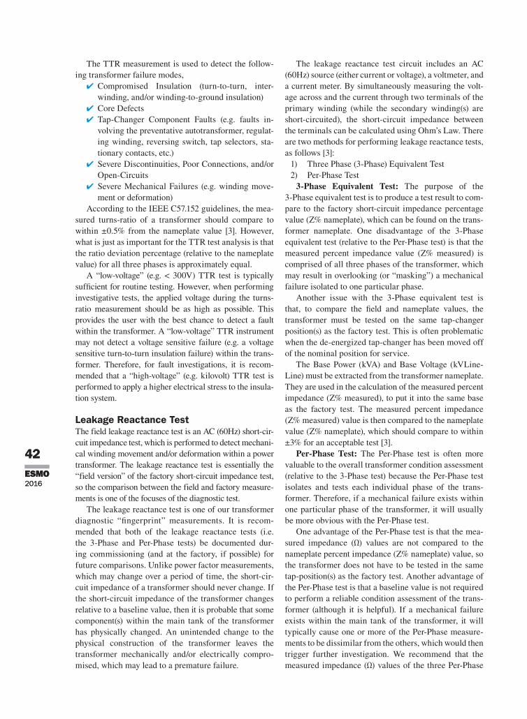
the ttr measurement is used to detect the follow-ing transformer failure modes,
✔ Compromised Insulation (turn-to-turn, inter-winding, and/or winding-to-ground insulation)
✔ Core Defects ✔ tap-Changer Component faults (e.g. faults in-volving the preventative autotransformer, regulat-ing winding, reversing switch, tap selectors, sta-tionary contacts, etc.)
✔ severe Discontinuities, Poor Connections, and/or open-Circuits
✔ severe mechanical failures (e.g. winding move-ment or deformation)
according to the Ieee C57.152 guidelines, the mea-sured turns-ratio of a transformer should compare to within ±0.5% from the nameplate value [3]. however, what is just as important for the ttr test analysis is that the ratio deviation percentage (relative to the nameplate value) for all three phases is approximately equal.
a “low-voltage” (e.g. < 300V) ttr test is typically sufficient for routine testing. however, when performing investigative tests, the applied voltage during the turns-ratio measurement should be as high as possible. this provides the user with the best chance to detect a fault within the transformer. a “low-voltage” ttr instrument may not detect a voltage sensitive failure (e.g. a voltage sensitive turn-to-turn insulation failure) within the trans-former. therefore, for fault investigations, it is recom-mended that a “high-voltage” (e.g. kilovolt) ttr test is performed to apply a higher electrical stress to the insula-tion system.
Leakage Reactance Testthe field leakage reactance test is an aC (60hz) short-cir-cuit impedance test, which is performed to detect mechani-cal winding movement and/or deformation within a power transformer. the leakage reactance test is essentially the “field version” of the factory short-circuit impedance test, so the comparison between the field and factory measure-ments is one of the focuses of the diagnostic test.
the leakage reactance test is one of our transformer diagnostic “fingerprint” measurements. It is recom-mended that both of the leakage reactance tests (i.e. the 3-Phase and Per-Phase tests) be documented dur-ing commissioning (and at the factory, if possible) for future comparisons. Unlike power factor measurements, which may change over a period of time, the short-cir-cuit impedance of a transformer should never change. If the short-circuit impedance of the transformer changes relative to a baseline value, then it is probable that some component(s) within the main tank of the transformer has physically changed. an unintended change to the physical construction of the transformer leaves the transformer mechanically and/or electrically compro-mised, which may lead to a premature failure.
the leakage reactance test circuit includes an aC (60hz) source (either current or voltage), a voltmeter, and a current meter. By simultaneously measuring the volt-age across and the current through two terminals of the primary winding (while the secondary winding(s) are short-circuited), the short-circuit impedance between the terminals can be calculated using ohm’s law. there are two methods for performing leakage reactance tests, as follows [3]:
1) three Phase (3-Phase) equivalent test2) Per-Phase test
3-Phase Equivalent Test: the purpose of the 3-Phase equivalent test is to produce a test result to com-pare to the factory short-circuit impedance percentage value (Z% nameplate), which can be found on the trans-former nameplate. one disadvantage of the 3-Phase equivalent test (relative to the Per-Phase test) is that the measured percent impedance value (Z% measured) is comprised of all three phases of the transformer, which may result in overlooking (or “masking”) a mechanical failure isolated to one particular phase.
another issue with the 3-Phase equivalent test is that, to compare the field and nameplate values, the transformer must be tested on the same tap-changer position(s) as the factory test. this is often problematic when the de-energized tap-changer has been moved off of the nominal position for service.
the Base Power (kVa) and Base Voltage (kVline-line) must be extracted from the transformer nameplate. they are used in the calculation of the measured percent impedance (Z% measured), to put it into the same base as the factory test. the measured percent impedance (Z% measured) value is then compared to the nameplate value (Z% nameplate), which should compare to within ±3% for an acceptable test [3].
Per-Phase Test: the Per-Phase test is often more valuable to the overall transformer condition assessment (relative to the 3-Phase test) because the Per-Phase test isolates and tests each individual phase of the trans-former. therefore, if a mechanical failure exists within one particular phase of the transformer, it will usually be more obvious with the Per-Phase test.
one advantage of the Per-Phase test is that the mea-sured impedance (Ω) values are not compared to the nameplate percent impedance (Z% nameplate) value, so the transformer does not have to be tested in the same tap-position(s) as the factory test. another advantage of the Per-Phase test is that a baseline value is not required to perform a reliable condition assessment of the trans-former (although it is helpful). If a mechanical failure exists within the main tank of the transformer, it will typically cause one or more of the Per-Phase measure-ments to be dissimilar from the others, which would then trigger further investigation. We recommend that the measured impedance (Ω) values of the three Per-Phase
43ESMO
2016
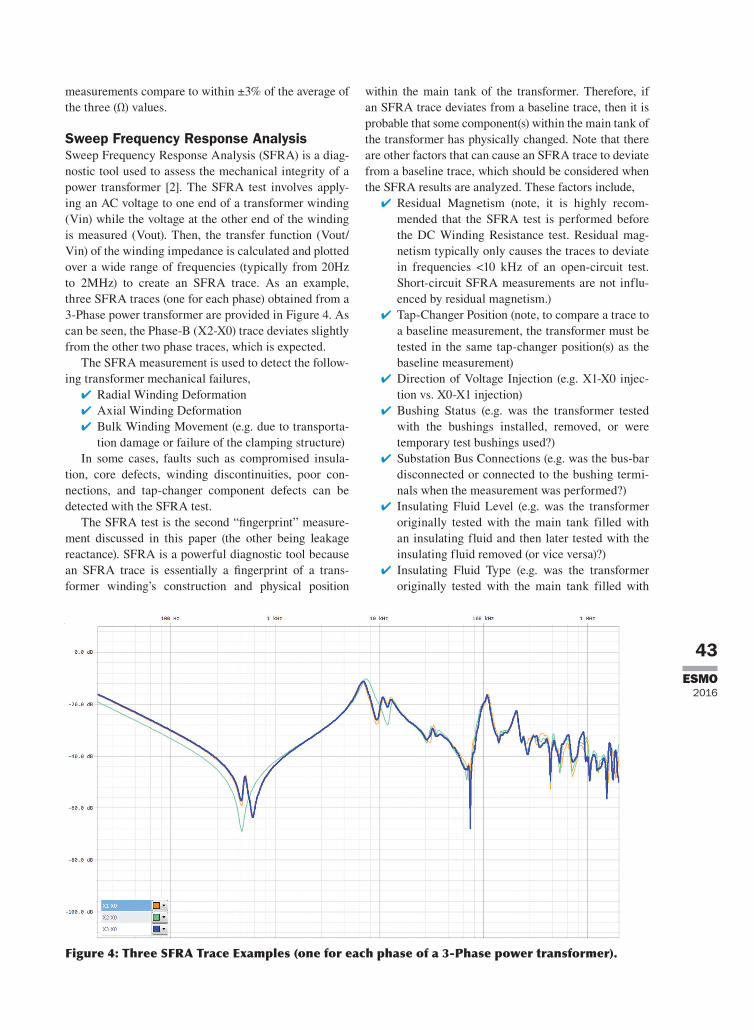
Figure 4: Three SFRA Trace Examples (one for each phase of a 3-Phase power transformer).
measurements compare to within ±3% of the average of the three (Ω) values.
Sweep Frequency Response Analysissweep frequency response analysis (sfra) is a diag-nostic tool used to assess the mechanical integrity of a power transformer [2]. the sfra test involves apply-ing an aC voltage to one end of a transformer winding (Vin) while the voltage at the other end of the winding is measured (Vout). then, the transfer function (Vout/Vin) of the winding impedance is calculated and plotted over a wide range of frequencies (typically from 20hz to 2mhz) to create an sfra trace. as an example, three sfra traces (one for each phase) obtained from a 3-Phase power transformer are provided in figure 4. as can be seen, the Phase-B (X2-X0) trace deviates slightly from the other two phase traces, which is expected.
the sfra measurement is used to detect the follow-ing transformer mechanical failures,
✔ radial Winding Deformation ✔ axial Winding Deformation ✔ Bulk Winding movement (e.g. due to transporta-tion damage or failure of the clamping structure)
In some cases, faults such as compromised insula-tion, core defects, winding discontinuities, poor con-nections, and tap-changer component defects can be detected with the sfra test.
the sfra test is the second “fingerprint” measure-ment discussed in this paper (the other being leakage reactance). sfra is a powerful diagnostic tool because an sfra trace is essentially a fingerprint of a trans-former winding’s construction and physical position
within the main tank of the transformer. therefore, if an sfra trace deviates from a baseline trace, then it is probable that some component(s) within the main tank of the transformer has physically changed. note that there are other factors that can cause an sfra trace to deviate from a baseline trace, which should be considered when the sfra results are analyzed. these factors include,
✔ residual magnetism (note, it is highly recom-mended that the sfra test is performed before the DC Winding resistance test. residual mag-netism typically only causes the traces to deviate in frequencies <10 khz of an open-circuit test. short-circuit sfra measurements are not influ-enced by residual magnetism.)
✔ tap-Changer Position (note, to compare a trace to a baseline measurement, the transformer must be tested in the same tap-changer position(s) as the baseline measurement)
✔ Direction of Voltage Injection (e.g. X1-X0 injec-tion vs. X0-X1 injection)
✔ Bushing status (e.g. was the transformer tested with the bushings installed, removed, or were temporary test bushings used?)
✔ substation Bus Connections (e.g. was the bus-bar disconnected or connected to the bushing termi-nals when the measurement was performed?)
✔ Insulating fluid level (e.g. was the transformer originally tested with the main tank filled with an insulating fluid and then later tested with the insulating fluid removed (or vice versa)?)
✔ Insulating fluid type (e.g. was the transformer originally tested with the main tank filled with

44 ESMO2016
44 ESMO2016
mineral oil and then later tested with the main tank filled with a different type of insulating fluid?)
✔ test Voltage ✔ transformer ground Connection: transformer, test Instrument, and test leads
as can be surmised by the aforementioned list, it is critical that the test conditions are well documented when the sfra measurement is performed, to help guarantee repeatability when the measurement is per-formed at a later date.
If no baseline traces exist for a 3-Phase power trans-former, it is possible to analyze the results by comparing similar traces for the three phases (e.g. by comparing X1-X0 to X2-X0 to X3-X0). for most 3-Phase trans-former configurations (and especially for two-winding transformers), a baseline value is not required to per-form a reliable condition assessment of the transformer (although it is helpful). note, the effectiveness of analyz-ing the sfra measurements by using phase-compari-son increases with experience.
the sfra test is not required during factory testing. however, it is recommended that the test be specified by the purchaser. the factory test serves as a fingerprint for comparisons during commissioning and throughout the life-cycle of the transformer. many companies also require a factory sfra test with the transformer in its shipping configuration. this test is compared to a sec-ond test performed in this configuration, upon arrival at its destination, which helps determine if transportation damage has occurred.
DC Winding Resistance Testthe transformer DC Winding resistance test is a diag-nostic tool used to assess the continuity of the current carrying path between terminals of a power trans-former [1]. the DC Winding resistance test is essen-tially a “continuity check”, which is used to identify discontinuities, poor connections, and open-circuits involving one or more of the following transformer components,
✔ Windings (strands, cross-overs, and tap leads) ✔ Bushings and Bushing Connections (draw leads, draw lead pins, and pad connections)
✔ DetC and ltC components (barrier board con-nections, stationary contacts, tap selectors, divert-er switches, reversing switches, etc.)
✔ lead terminations (bolted joints, crimps, brazes, etc.)
the DC Winding resistance measurement circuit includes a DC source (traditionally a current source), a voltmeter, and a current meter. By simultaneously measuring the voltage across and the current through two terminals, the resistance between the terminals can be calculated using ohm’s law. although the DC Winding resistance measurement is a simple concept
that relies on the fundamental application of ohm’s law, performing the DC Winding resistance test quickly and accurately is often challenging [1]. the challenge is due to the fact that the transformer core must be saturated to remove the reactive component of the test circuit before the resistance can be isolated and measured.
the core saturation process is achieved by applying a DC voltage across a winding(s) over a period of time. In general, the higher the voltage across the winding(s), the less time it takes to achieve core saturation. Inter-estingly, most DC Winding resistance instruments utilize a DC current source, as opposed to a DC volt-age source. fortunately, the voltage across the winding is proportional to the test current injected through the winding. therefore, the higher the injected current, the higher the terminal voltage, the faster the measurement is performed.
also, testing low resistance windings (e.g. resis-tances <50mΩ) is often problematic because in order to achieve an adequate terminal voltage, the injected test current must be relatively large (e.g. >25a). therefore, for low resistance windings, a test current of at least 25a (and sometimes up to 50a) is recommended to perform the measurement in a short period of time.
the DC Winding resistance test results are analyzed using one or more of the following analysis techniques,
✔ Phase-comparison (note, temperature correction is not required)
✔ Comparison to a factory test (note, temperature correction may be required)
✔ Comparison to a previous field test (note, temper-ature correction may be required)
regardless of which analysis technique is used, it is expected that the resistance measurements compare to within ±2% [3]. furthermore, a discontinuity, poor con-nection, etc., results in an increased resistance within the current path, which increases the losses of the trans-former. such problems can generate significant heat during normal operation. therefore, to find supporting evidence that an overheating condition exists, it is recom-mended that the Dga results are analyzed in conjunction with the DC Winding resistance results [1].
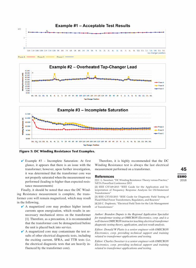
the test results for three DC Winding resistance measurements are provided in figure 5 and explained in detail below,
✔ example #1 – acceptable results: the winding resistance for all three phases compares to within ±2% for all tap-positions, and therefore, the mea-surement is acceptable
✔ example #2 – overheated tap-Changer lead: the Phase-B winding resistance is significantly higher than the other two phases for tap-positions 4l and 14r. Upon further investigation, an over-heated ltC tap-lead was found
45ESMO
2016
✔ example #3 – Incomplete saturation: at first glance, it appears that there is an issue with the transformer; however, upon further investigation, it was determined that the transformer core was not properly saturated when the measurement was performed (leading to higher than expected resis-tance measurements)
finally, it should be noted that once the DC Wind-ing resistance measurement is complete, the trans-former core will remain magnetized, which may result in the following,
✔ a magnetized core may produce higher inrush currents upon energization, which results in un-necessary mechanical stress on the transformer [1]. therefore, as a precaution, it is recommended that the transformer core be demagnetized before the unit is placed back into service.
✔ a magnetized core may contaminate the test re-sults of other electrical diagnostic tests, including the exciting current, sfra, and ttr tests (i.e. the electrical diagnostic tests that are heavily in-fluenced by the transformer core).
therefore, it is highly recommended that the DC Winding resistance test is always the last electrical measurement performed on a transformer.
References[1] C. L. Sweetser, “DC Winding Resistance: Theory versus Practice,” NETA PowerTest Conference 2013[2] IEEE C57.149-2013 “IEEE Guide for the Application and In-terpretation of Frequency Response Analysis for Oil-Immersed Transformers”[3] IEEE C57.152-2013 “IEEE Guide for Diagnostic Field Testing of Fluid-Filled Power Transformers, Regulators, and Reactors”[4] Jill C. Duplessis, “Electrical Field Tests for the Life Management of Transformers”
Author: Brandon Dupuis is the Regional Application Specialist for transformer testing at OMICRON Electronics, corp. and is a well-known OMICRON instructor teaching electrical transformer diagnostic testing theory, application, and test result analysis.
Editor: Donald W Platts is a senior engineer with OMICRON Electronics, corp. providing technical support and training related to transformer applications and testing.
Editor: Charles Sweetser is a senior engineer with OMICRON Electronics, corp. providing technical support and training related to transformer applications and testing.
Figure 5: DC Winding Resistance Test Examples.


