Embed Size (px)
Citation preview

An Introduction to Air Traffic Control Facilities Course No: A03-007
Credit: 3 PDH
J. Paul Guyer, P.E., R.A., Fellow ASCE, Fellow AEI
Continuing Education and Development, Inc. 9 Greyridge Farm Court Stony Point, NY 10980 P: (877) 322-5800 F: (877) 322-4774 [email protected]
© J. Paul Guyer 2015 1
J. Paul Guyer, P.E., R.A. Editor Paul Guyer is a registered civil engineer, mechanical engineer, fire protection engineer and architect with 35 years of experience designing buildings and related infrastructure. For an additional 9 years he was a principal staff advisor to the California Legislature on capital outlay and infrastructure issues. He is a graduate of Stanford University and has held numerous national, state and local offices with the American Society of Civil Engineers, Architectural Engineering Institute and National Society of Professional Engineers. He is a Fellow of ASCE and AEI.
An Introduction to Air Traffic Control Facilities

© J. Paul Guyer 2015 2
CONTENTS 1. TERMINAL RADAR APPROACH CONTROL FACILITY (TRACON) 2. AREA CONTROL AND SURVEILLANCE FACILITY (ACSFAC) 3. JOINT CONTROL FACILITY (JCF) 4. AIR TRAFFIC CONTROL TOWER 5. AIR TRAFFIC CONTROL TOWER BASE BUILDING (This publication is adapted from the Unified Facilities Criteria of the United States government which are in the public domain, are authorized for unlimited distribution, and are not copyrighted.)
© J. Paul Guyer 2015 3
1 TERMINAL RADAR APPROACH CONTROL FACILITY (TRACON)
1.1 FUNCTION. The TRACON building contains equipment used for controlling air traffic
and is staffed by air traffic controllers and air operations, administrative, and maintenance
support personnel. The ASR, PAR, PALS, transmitting and receiving sites, and navigation
aids (NAVAIDS), which are remotely located, are monitored and controlled in the
TRACON. The TRACON contains an IFR control room which includes the radar display
consoles and communications control equipment. An adjacent terminal equipment room
houses automation central (or terminal) equipment, maintenance positions and
audio/video tape recorders. An office for the FAA liaison officer may be required at
terminal radar approach control facilities.
1.2 LOCATION. Locate the TRACON building adjacent to the air traffic control tower and
aircraft operations building where siting requirements permit.
1.3 ARCHITECTURAL AND STRUCTURAL REQUIREMENTS. Provide the following:
a) Removable, modular, access flooring in the IFR and terminal equipment rooms
with 18 inches of clearance provided between the floor panels and subfloor to
accommodate wiring and insulated piping.
b) A 9-foot clear ceiling height above accessible flooring.
c) Built-in workbenches and shelving in the terminal equipment room.
d) Facility and restroom areas readily accessible by the physically handicapped.
e) Interior and exterior acoustical treatment to attain the room criteria. Soft textured
acoustical wall panels in the IFR control room.
f) Cable troughs or conduits between the air traffic control tower and the TRACON
for intrafacility cabling. The exact dimensions of the cable trough or size and
number of conduits are specified by the Owner.
1.3.1 WINDOWS. Do not provide windows in IFR or terminal equipment rooms. Provide
insulated glazing for noise reduction in administrative areas.
© J. Paul Guyer 2015 4
1.4 ELECTRICAL REQUIREMENTS
1.4.1 UNINTERRUPTED POWER SUPPLY (UPS). Provide non-redundant UPS. Use the
anticipated load to determine the size of the UPS.
1.4.2 EMERGENCY ELECTRICAL POWER. Provide an emergency generator with
automatic starting and switching capability. Provide emergency power to the following:
a) Loads as required by NFPA-101.
b) Electronic equipment in the IFR and terminal equipment rooms.
c) Mechanical systems supporting electronic equipment.
d) Exterior security lighting and security systems.
1.4.3 400-HZ POWER. Provide 400-Hz power when required by the Owner.
1.5 LIGHTING. Design lighting in accordance with Owner requirements. Provide dimmer
adjustable red lights in the IFR room.
© J. Paul Guyer 2015 5
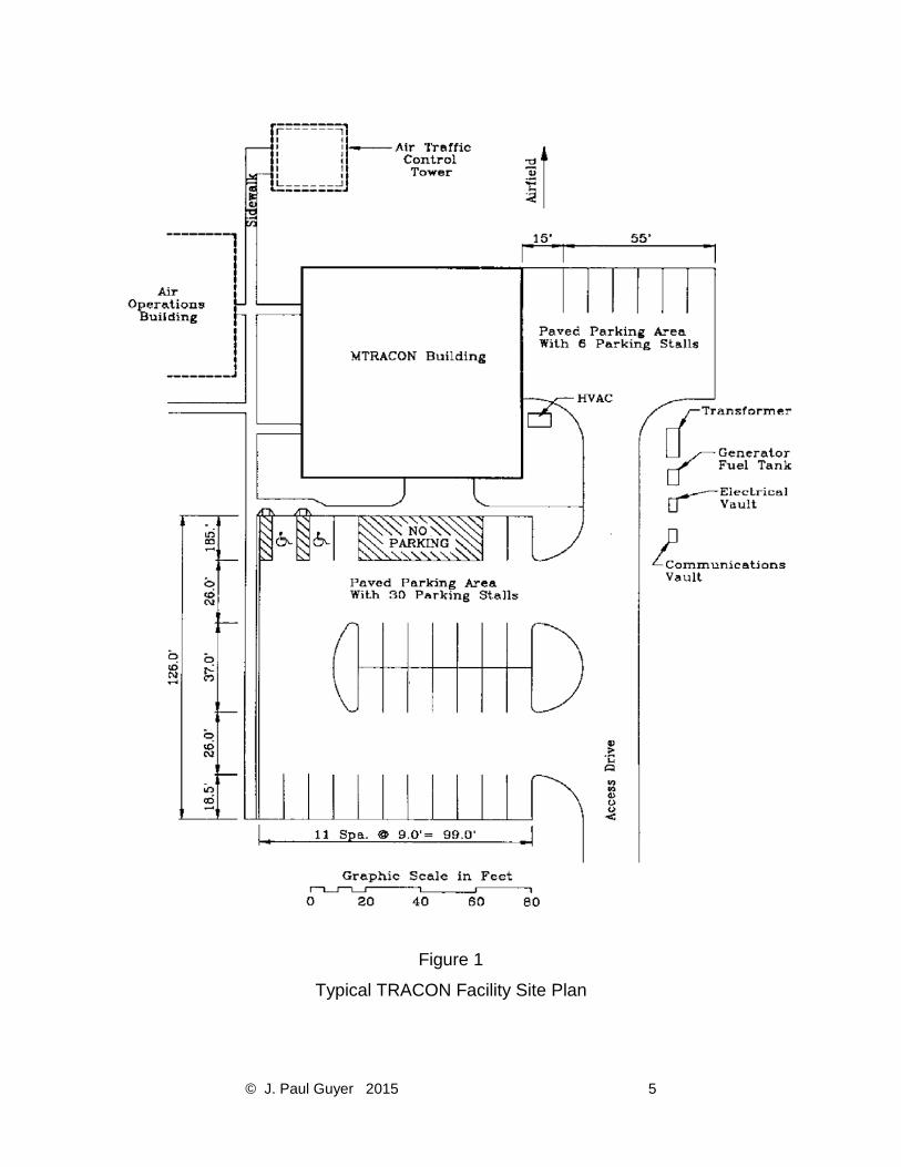
Figure 1
Typical TRACON Facility Site Plan

© J. Paul Guyer 2015 6
Figure 2
Typical TRACON Building Layout
© J. Paul Guyer 2015 7
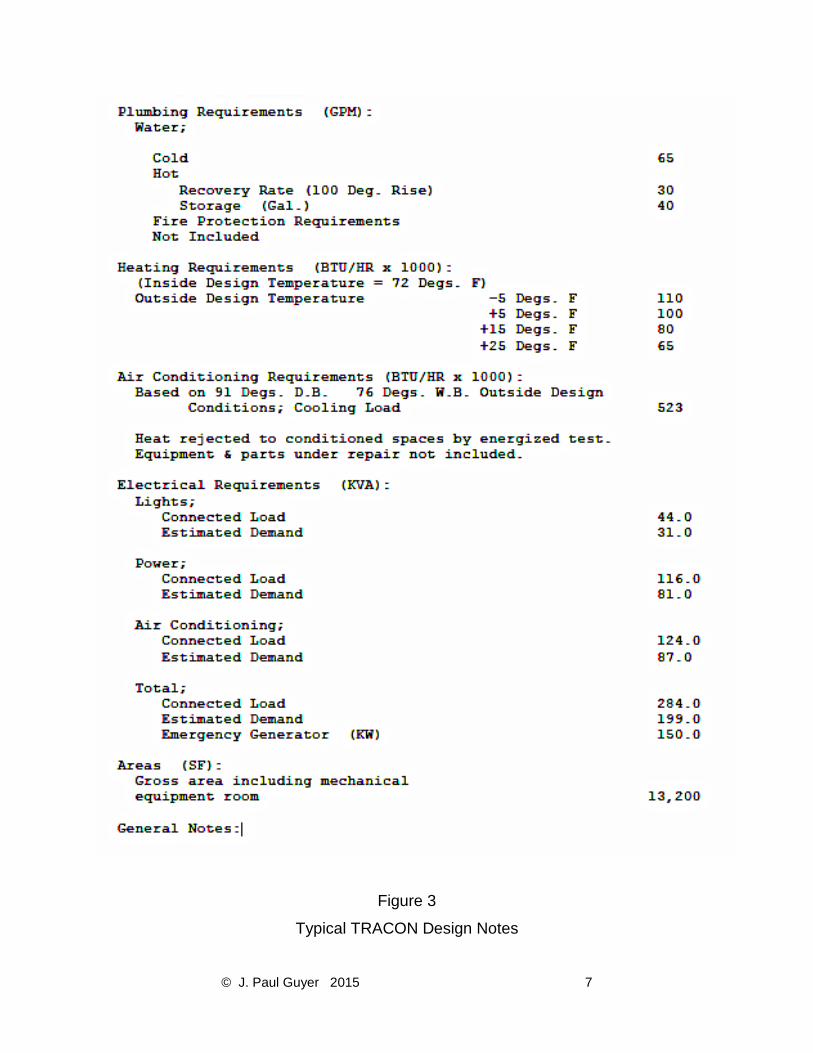
Figure 3
Typical TRACON Design Notes

© J. Paul Guyer 2015 8
1.6 SECURITY. The TRACON is normally located within restricted areas which typically
meet the minimum security measures for external security. If the facility is located within
a restricted area of a lower level of security or is located remote and outside of an
established restricted area, provide additional measures to meet the minimum security
requirements for the level of security assigned to the facility. Security at the main building
entrance usually requires a single entry point with visitor control. Remote locks, video
cameras, card readers, and/or key pads may be required by the Owner as components
of the IDS. The level of security and the designer's responsibility for particular security
elements will be designated in the Owner. Provide the following:
a) Electronic cipher door locks at interior entrance doors to IFR and terminal
equipment rooms.
b) Exterior doors in emergency generator/electrical and terminal equipment rooms
with no access hardware on the outside.
1.7 ADDITIONAL DESIGN CRITERIA. Refer to Owner for facility design requirements
not addressed above.

© J. Paul Guyer 2015 9
2. AREA CONTROL AND SURVEILLANCE FACILITY (ACSFAC)
2.1 FUNCTION. The ACSFAC building houses equipment and personnel to provide a
variety of services to air, surface, and subsurface units. These services are provided to
both users and include radar surveillance and various forms of air traffic control in warning
and other special airspace areas. Other services may include surface operating area
management, ground controlled intercept, operating area scheduling, and range control.
The ACSFAC normally operates continuously.
2.2 LOCATION. Locate the ACSFAC building as a stand-alone facility.
2.3 ARCHITECTURAL AND STRUCTURAL REQUIREMENTS. Provide the following:
a) Removable, modular, access flooring in the operations, system, and the
equipment/maintenance rooms with 18 inches of clearance provided between the
floor panels and subfloor to accommodate wiring and insulated piping.
b) Interior and exterior acoustical treatment to attain the room criteria required. Soft
textured acoustical wall panels and movable sound absorbent partitions in the
operations room.
c) A clear ceiling height of 14 feet (finished floor to ceiling) in the operations area.
d) A tiered seating area in projection auditorium.
e) RF shielding throughout the crypto room.
f) Facility and restroom areas readily accessible by the physically handicapped.
2.3.1 WINDOWS. Do not provide windows in operations, designated system, and
equipment/maintenance rooms. Provide insulated glazing for noise reduction in
administrative areas.
2.4 MECHANICAL REQUIREMENTS. Design the mechanical system to meet the criteria
required. Provide the following:
© J. Paul Guyer 2015 10
a) Automatic thermostatic control.
b) A four-pipe chilled/hot water distribution system with separate air handlers for each
zone or dehumidifying system to work in conjunction with the air conditioning
system.
c) Capability for future expansion of the HVAC system. Use piping designed for low
friction and velocity losses at the maximum flows expected.
d) Chilled water system in accordance with Owner requirements.
© J. Paul Guyer 2015 11
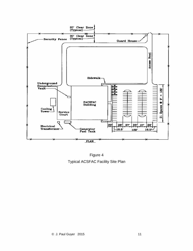
Figure 4
Typical ACSFAC Facility Site Plan
© J. Paul Guyer 2015 12
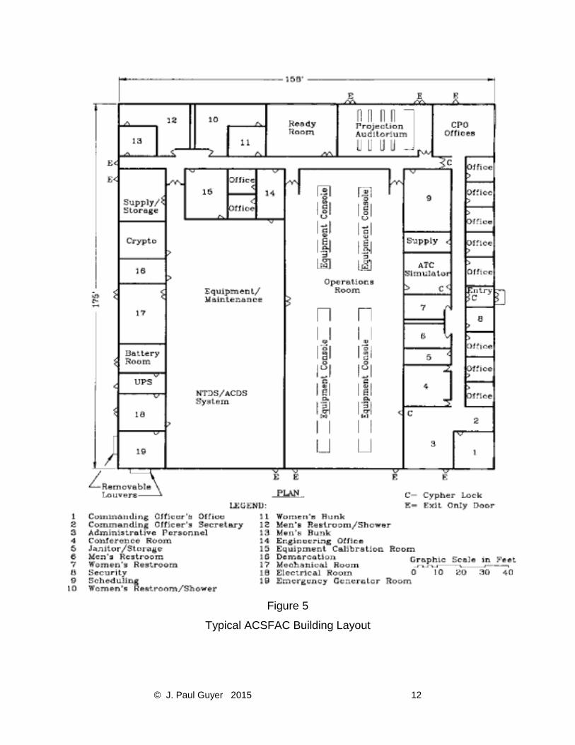
Figure 5
Typical ACSFAC Building Layout

© J. Paul Guyer 2015 13
Figure 6
Typical ACSFAC Design Notes

© J. Paul Guyer 2015 14
2.4.1 AIR CONDITIONING. Provide the following:
a) Two parallel piped air cooled chillers, each designed for 60 percent of the total
building cooling load. Alternate operation of chillers automatically on a regular
basis when load is less than 60 percent. Consider cold storage to minimize power
peaks.
b) One chilled water circulation pump for each chiller plus a manifold spare pump.
Design chiller circuitry so that the pump shall operate and water flow before the
chiller is energized. The spare pump may be manually operated. Provide
secondary chilled water loops with three-way valves at coils in each circuit to result
in constant flow through chiller.
c) Divide the building into three cooling zones: administrative areas, operations
areas, and the equipment areas. Provide separate air handlers and ducting
systems for each zone. Provide sound attenuaters for supply duct work. Consider
more than one air handler for large zones.
d) Provide two air handlers for the operations, the NTDS/ACDS, and terminal
distribution rooms. Design air handler controls to regulate the units as primary and
secondary with each unit alternating as the primary. Provide air handlers capable
of controlling humidity, equipped with electric heat, and specifically designed for
computer room applications.
2.4.2 HEATING. Provide fuel oil or gas operated boiler heating system designed to
accommodate the largest heating load anticipated. Provide two circulation pumps, each
designed for 100 percent of the total building heating load. Design the pump controls to
regulate the pumps as primary and secondary with each pump alternating as the primary.
2.5 ELECTRICAL REQUIREMENTS. 2.5.1 UNINTERRUPTED POWER SUPPLY (UPS). Provide non-redundant UPS in
accordance with Owner requirements. Use anticipated load to determine the size of UPS.
© J. Paul Guyer 2015 15
2.5.2 EMERGENCY ELECTRICAL POWER. Provide an emergency generator with
automatic starting and switching capability. Provide emergency power to the following:
a) Loads as required by NFPA-101.
b) Electronic equipment in operations, the NTDS/ACDS, and equipment rooms.
c) Building mechanical systems supporting electronic equipment.
d) Exterior security lighting and security systems.
2.5.3 400-HZ POWER. Provide 400-Hz power in accordance with Owner requirements.
2.6 SECURITY. The facility is normally located within restricted areas which meet the
minimum security measures for external security. When the facility is located within a
restricted area of a lower level of security or is located remote and outside of an
established restricted area. Provide additional measures to meet the minimum security
requirements for the level of security assigned to the facility. Security at the main entrance
usually requires a single entry point with visitor control. Remote locks, video cameras,
card readers, and/or key pads may be required by Owner as components of the IDS. The
level of security and the designer's responsibility for particular security elements will be
designated by the Owner. Provide the following:
a) Electronic cipher door locks at access points to operations room.
b) Exterior doors in the operations, the Owner-designated areas,
equipment/maintenance, and mechanical/electrical rooms with no access
hardware on the outside.
c) CCTV.
d) Security fencing and guard post for facilities located outside the secure area of
the installation.
e) Personnel identification, visitor check-in, and control system to control ingress
and egress.

© J. Paul Guyer 2015 16
2.7 ADDITIONAL DESIGN CRITERIA. Refer to Owner requirements for facility design
requirements not addressed above.
© J. Paul Guyer 2015 17
3. JOINT CONTROL FACILITY (JCF)
3.1 FUNCTION. The JCF is a high density (air traffic) facility which collocates approach
control responsibilities for two or more air airfields or a combination of an approach control
facility and a ACSFAC or Range Operations Center (ROC) under one roof. The JCF
normally operates continuously.
3.2 LOCATION. Locate the JCF adjacent to the air operations building when siting criteria
permits. An air traffic control tower may be sited with the JCF.
3.3 ARCHITECTURAL AND STRUCTURAL REQUIREMENTS. Provide the following:
a) Removable, modular, access flooring in the operations, the areas designated
by the Owner, and the equipment/maintenance rooms with 18 inches of
clearance provided between the floor panels and subfloor to accommodate
wiring and insulated piping.
b) Interior and exterior acoustical treatment to attain the room criteria required by
the Owner. Soft textured acoustical wall panels and movable sound absorbent
partitioning in the operations room.
c) A clear ceiling height of 14 feet (finished floor to ceiling) in the operations area.
d) A tiered seating area in projection auditorium.
e) RF shielding throughout the crypto room.
f) Facility and restroom areas readily accessible by the physically handicapped.
g) Cable troughs or conduits between the air traffic control tower and the JCF for
intrafacility cabling.
3.3.1 WINDOWS. Do not use windows in operations, Owner-designated areas, and
equipment/maintenance rooms. Provide insulated glazing for noise reduction in
administrative areas.

© J. Paul Guyer 2015 18
3.4 MECHANICAL REQUIREMENTS. Provide the following:
a) Automatic thermostatic control.
b) A four-pipe chilled/hot water distribution system with separate air handlers for each
zone or dehumidifying system to work in conjunction with the air conditioning
system.
c) Capability for future expansion of the HVAC system. Use piping designed for low
friction and velocity losses at the maximum flows expected.
d) Chilled water for designated areas in accordance with Owner requirements.
© J. Paul Guyer 2015 19
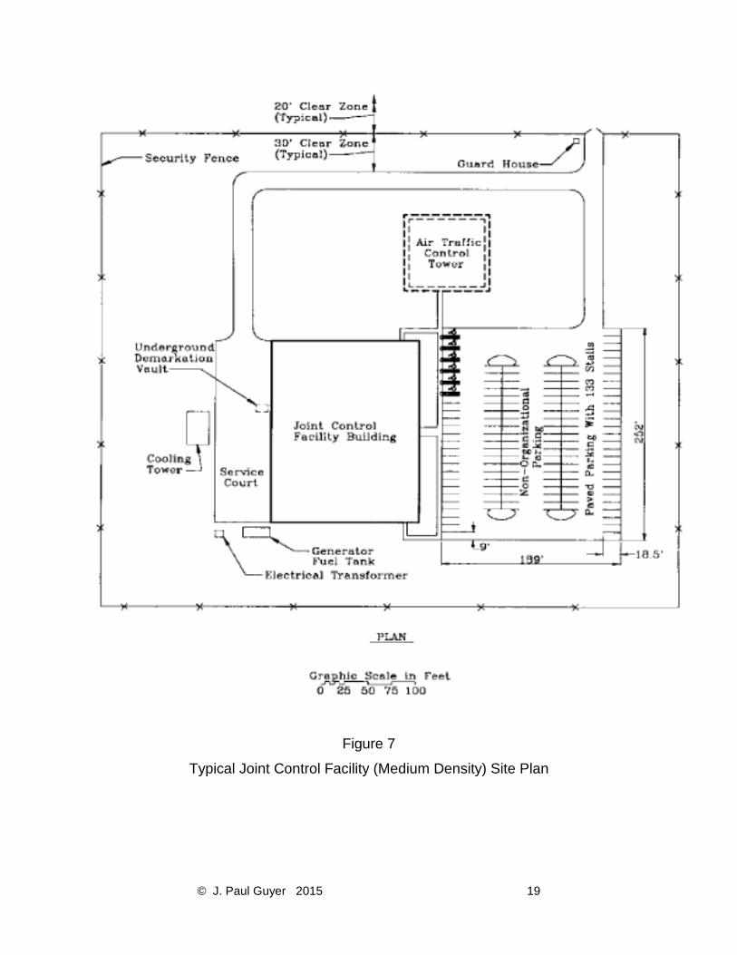
Figure 7
Typical Joint Control Facility (Medium Density) Site Plan
© J. Paul Guyer 2015 20
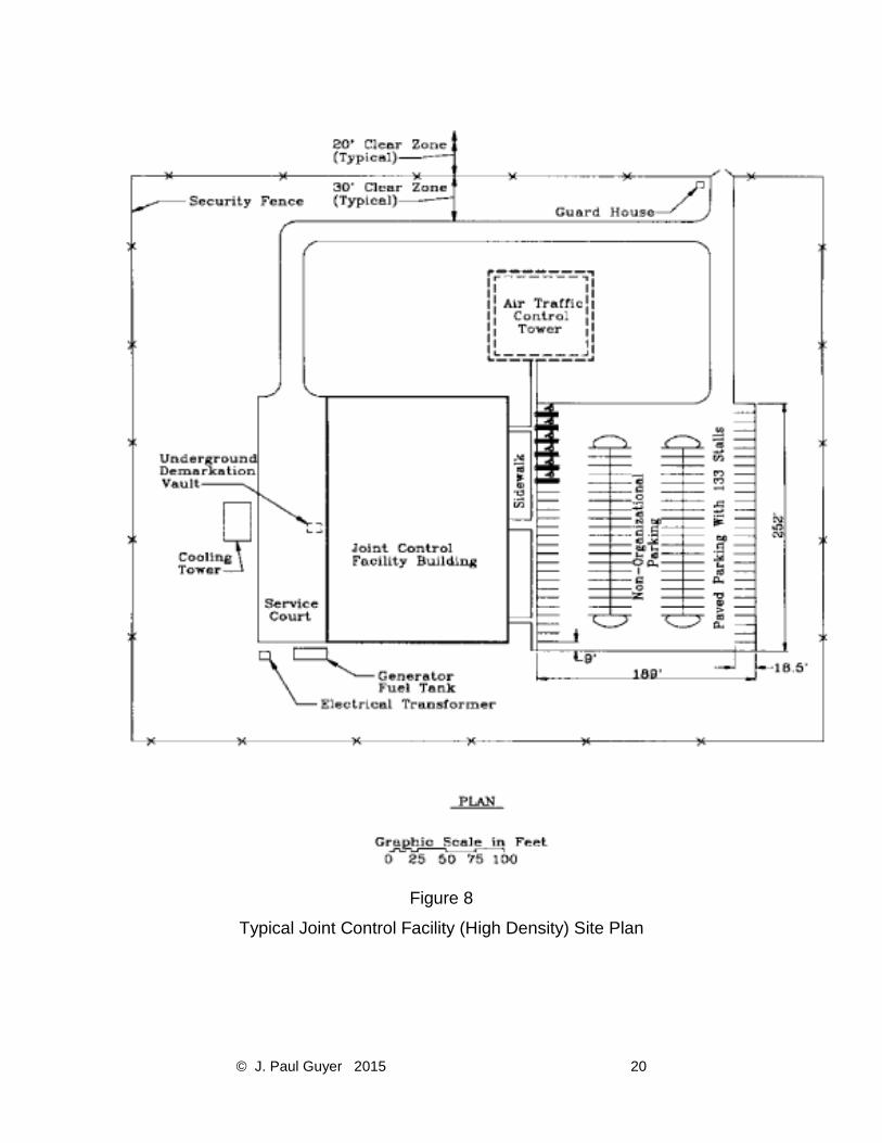
Figure 8
Typical Joint Control Facility (High Density) Site Plan

© J. Paul Guyer 2015 21
Figure 9
Typical Joint Control Facility (Medium Density) Building Layout

© J. Paul Guyer 2015 22
Figure 10
Typical Joint Control Facility (High Density) Building Layout
© J. Paul Guyer 2015 23
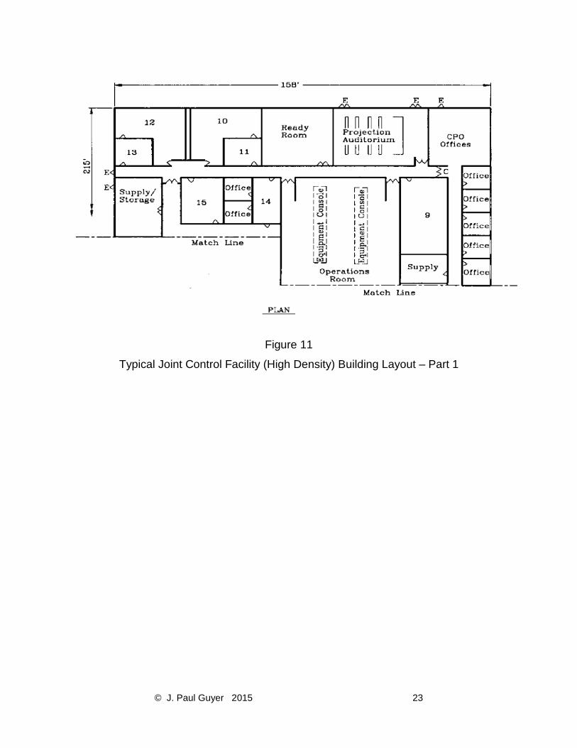
Figure 11
Typical Joint Control Facility (High Density) Building Layout – Part 1
© J. Paul Guyer 2015 24
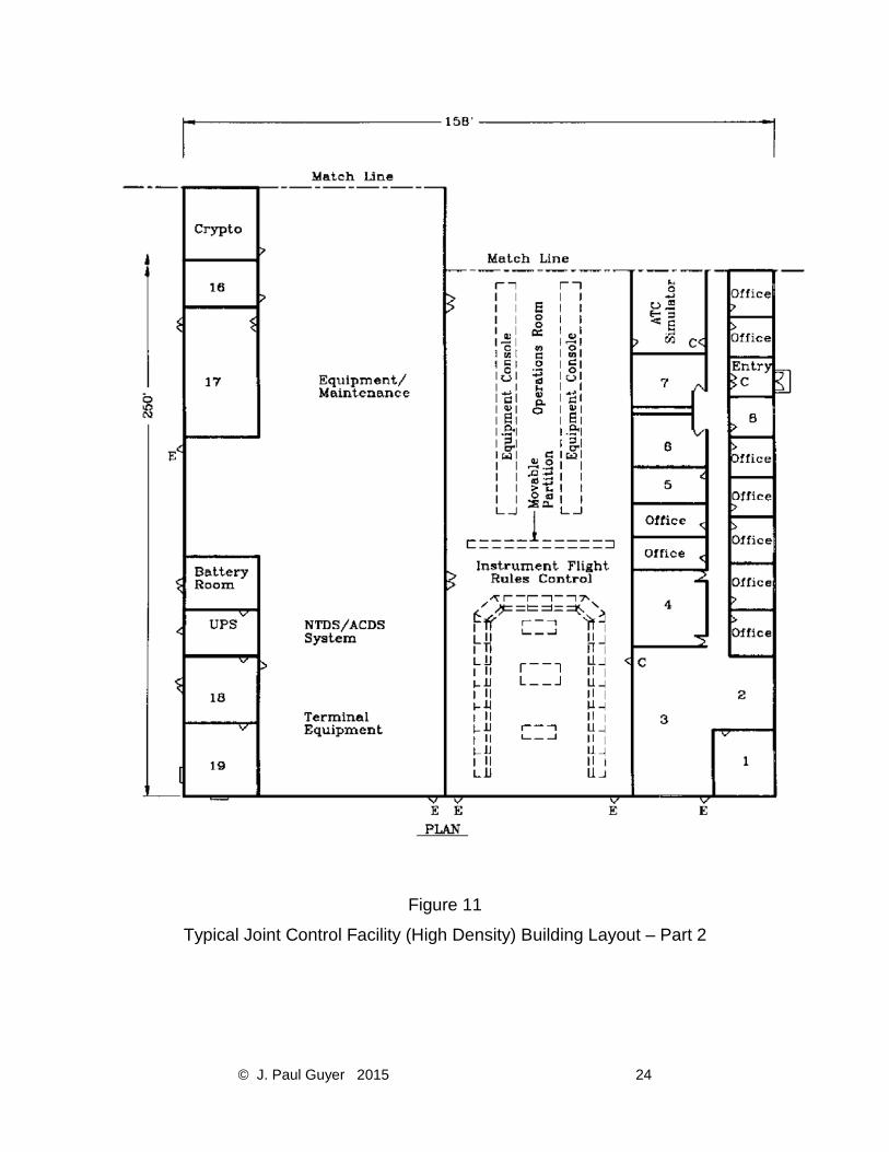
Figure 11
Typical Joint Control Facility (High Density) Building Layout – Part 2
© J. Paul Guyer 2015 25
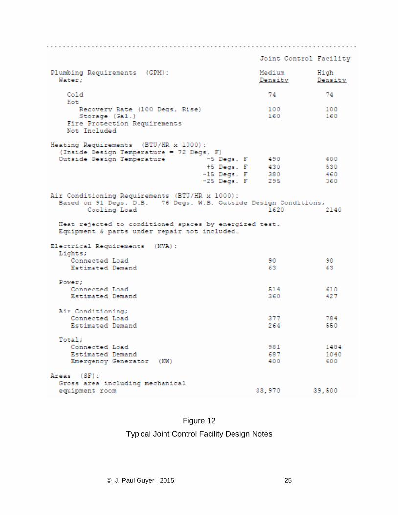
Figure 12
Typical Joint Control Facility Design Notes

© J. Paul Guyer 2015 26
3.4.1 AIR CONDITIONING. Provide the following:
a) Two parallel piped air cooled chillers, each designed for 60 percent of the total
building cooling load. Alternate operation of chillers automatically on a regular
basis when load is less than 60 percent. Consider cold storage to minimize power
peaks.
b) One chilled water circulation pump for each chiller plus a manifold spare pump.
Design chiller circuitry so that the pump shall operate and water flow before the
chiller is energized. The spare pump may be manually operated. Provide
secondary chilled water loops with three-way valves at coils in each circuit to result
in constant flow through chiller.
c) Divide the building into three cooling zones: administrative areas, operations
areas, and the equipment areas. Provide separate air handlers and ducting
systems for each zone. Provide sound attenuators for supply duct work. Consider
more than one air handler for large zones.
d) Provide two air handlers for the operations and other Owner-designated spaces,
and terminal distribution rooms. Design the air handler controls to regulate the
units as primary and secondary with each unit alternating as the primary. Provide
air handlers capable of controlling humidity, equipped with electric heat, and
specifically designed for computer room applications.
3.4.2 HEATING. Provide fuel oil or gas operated boiler heating system designed to
accommodate the largest heating load anticipated. Provide two circulation pumps, each
designed for 100 percent of the total building heating load. Design the pump controls to
regulate the pumps as primary and secondary with each pump alternating as the primary.
3.5 ELECTRICAL REQUIREMENTS 3.5.1 UNINTERRUPTED POWER SUPPLY (UPS). Provide non-redundant UPS. Use
anticipated load to determine the size of UPS.

© J. Paul Guyer 2015 27
3.5.2 EMERGENCY ELECTRICAL POWER. Provide an emergency generator with
automatic starting and switching capability. Provide emergency power to the following:
a) Loads as required by NFPA-101.
b) Electronic equipment in operations, the other Owner-designated spaces, and
equipment rooms.
c) Building mechanical systems supporting electronic equipment.
d) Exterior security lighting and security systems.
3.5.3 400-HZ POWER. Provide 400-Hz power for the Owner-designated spaces.
3.6 LIGHTING. Provide dimmer adjustable red lighting in the IFR room.
3.7 SECURITY. The JCF is normally located within restricted areas which meet the
minimum security measures for external security. If the facility is located within a restricted
area of a lower level of security or is located remote and outside of an established
restricted area, provide additional measures to meet the minimum security requirements
for the level of security assigned to the facility. Security at the main building entrance
usually requires a single entry point with visitor control. Remote locks, video cameras,
card readers, and/or key pads may be required by the Owner as components of the IDS.
The level of security and the designer's responsibility for particular security elements will
be designated in the Owner. Provide the following:
a) Electronic cipher door locks at access points to operations room.
b) Exterior doors in operations and other Owner-designated spaces,
equipment/maintenance, and mechanical/electrical rooms with no access
hardware on the outside.
c) CCTV.
d) Security fencing and guard post for facilities located outside of the secure area of
the installation.
© J. Paul Guyer 2015 28
e) Personnel identification, visitor check-in, and control system to control ingress and
egress.
3.8 ADDITIONAL DESIGN CRITERIA. Refer to Owner for facility design requirements
not addressed above.

© J. Paul Guyer 2015 29
4. AIR TRAFFIC CONTROL TOWER
4.1 FUNCTION. The air traffic control tower building houses equipment and personnel for
visual flight rules (VFR) control of aircraft approaching and departing the terminal area or
airport and aircraft and vehicular movement on the runways, taxiways, and other
operation areas.
4.2 TOWER LOCATION AND HEIGHT. Locate the air traffic control tower building on the
edge of the airfield, situated to have an unobstructed line-of-sight to the aircraft approach
areas, runways, taxiways, aircraft parking areas, and other operational areas over which
aircraft movements are to be controlled. Provide a tower location and height to result in
the tower cab eye level line of site intersecting airport traffic surfaces at a vertical angle
of 35 minutes or greater. Refer to FAA Order 6480.4, Airport Traffic
Control Tower Siting Criteria.
4.3 ARCHITECTURAL AND STRUCTURAL REQUIREMENTS. The air traffic control
tower is categorized as low or high density based on air traffic volume. Refer to FAA Order
6480.7, Airport Traffic Control Tower and Terminal Radar Approach Control Facility
Design. Consider the use of prefabricated modular construction for tower and tower cab.
Provide the following:
a) Removable, modular, access flooring in the tower cab with 18 inches of clearance
provided between the floor panels and subfloor to accommodate wiring and
insulated piping.
b) Interior and exterior acoustical treatment to attain the Owner’s room criteria.
c) Clear span roof structure (no interior columns) in tower cab.
d) Roof hatch to provide access to the roof from the cab floor.
e) Floor hatch to allow moving equipment between the cab and the top elevator
landing.
f) Walkway around the exterior of the control cab to facilitate washing cab windows.
g) Traction type elevator.

© J. Paul Guyer 2015 30
h) Pressure relief system to equalize interior and exterior atmospheric pressures
during high wind conditions.
i) Electrically operated, retractable covers for cab windows at sites prone to
hurricane and typhoon conditions.
j) A 2,000-pound capacity, remote controlled, electric hoist in the tower cab. Suspend
hoist from tower cab roof framing.
k) A cable raceway to cab roof through tubular cab roof columns.
4.3.1 INTERIOR WALLS. Provide fire-rated walls for stair enclosure, plumbing and
electrical chases.
© J. Paul Guyer 2015 31
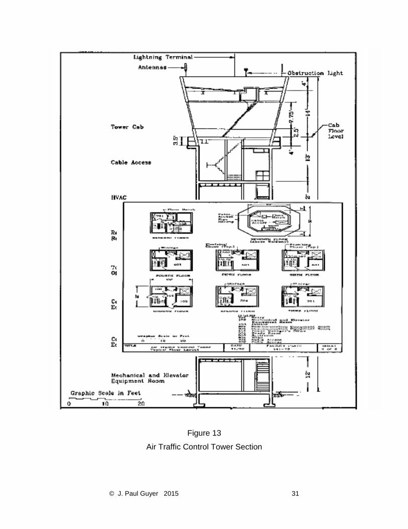
Figure 13
Air Traffic Control Tower Section
© J. Paul Guyer 2015 32
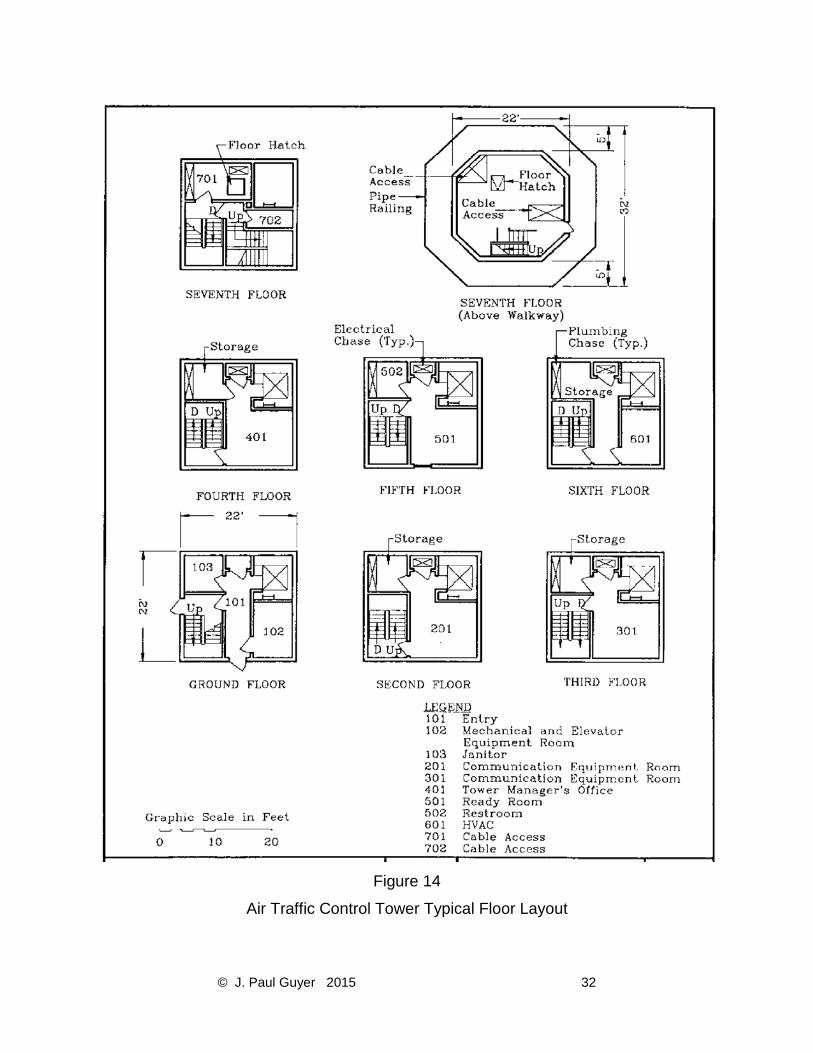
Figure 14
Air Traffic Control Tower Typical Floor Layout
© J. Paul Guyer 2015 33
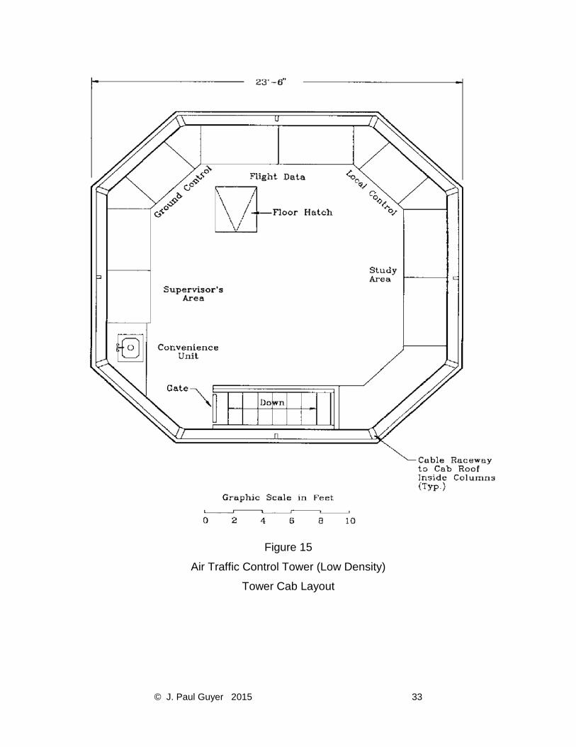
Figure 15
Air Traffic Control Tower (Low Density)
Tower Cab Layout

© J. Paul Guyer 2015 34
Figure 16
Air Traffic Control Tower (High Density)
Tower Cab Layout
© J. Paul Guyer 2015 35
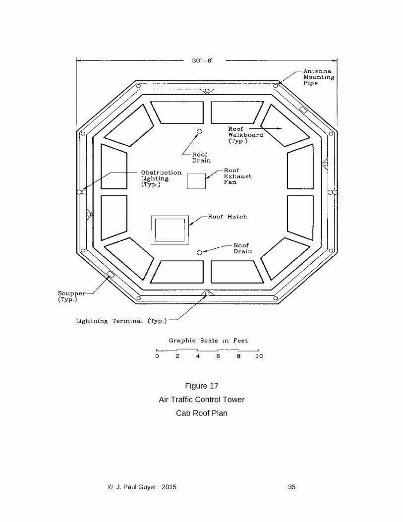
Figure 17
Air Traffic Control Tower
Cab Roof Plan
© J. Paul Guyer 2015 36
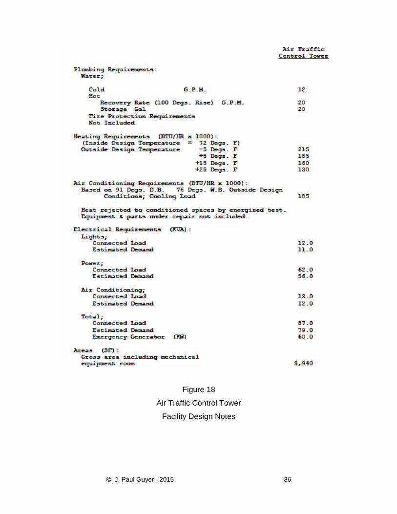
Figure 18
Air Traffic Control Tower
Facility Design Notes
© J. Paul Guyer 2015 37
4.3.2 WINDOWS. Do not use windows in tower structure. Provide tower cab with heat-
absorbing insulated window units in accordance with Owner requirements. Provide units
with a light transmissivity of not less than 85 percent, heat transmission (U value) of 0.60
maximum, and free of parallax or other optical distortion. Provide spare window units
interchangeable with any other similar unit in the tower cab. Provide window shades for
tower cab windows. Refer to FAA Specification FAA-E-2470.
4.4 MECHANICAL REQUIREMENTS. Use peripheral strip cooling diffusers to reduce
solar impact to the personnel and wall diffusers to control tower cab temperatures.
4.5 ELECTRICAL REQUIREMENTS
4.5.1 EMERGENCY ELECTRICAL POWER. Provide an emergency generator with
automatic starting and switching capability. Consider a common generator when the air
traffic control tower is sited adjacent to the air operations building, TRACON, ACSFAC,
JCF, or tower base building. Provide emergency power to the following:
a) Loads as required by NFPA-101.
b) Electronic equipment in the tower cab and communications equipment rooms.
c) Building mechanical systems supporting electronic equipment.
d) Exterior security lighting and security systems.
4.5.2 UNINTERRUPTED POWER SUPPLY (UPS). Provide non-redundant UPS. Use
anticipated load to determine the size of UPS.
4.6 LIGHTING. Design lighting in accordance with Owner requirements. Provide dimmer
adjustable white ceiling lights in tower cab. Provide down lighting over work areas on
separate switch.
© J. Paul Guyer 2015 38
4.7 FIRE PROTECTION. Refer to NFPA 101. Consult local fire prevention agency to
determine if air traffic control tower meets height criteria to be classified as a "High Rise
Building."
4.8 SECURITY. Air traffic control towers are normally located within restricted areas
which meet the minimum security measures for external security. If the facility is located
within a restricted area of a lower level of security, provide additional measures to meet
the minimum security requirements for the level of security assigned to the facility. The
level of security and the designer's responsibility for particular security elements will be
designated by the Owner. Provide an electronic cipher door lock at the first floor entrance
with an intercom and remote lock release in the tower cab.
4.9 ADDITIONAL DESIGN CRITERIA. Refer to Owner for facility design requirements
not addressed above.

© J. Paul Guyer 2015 39
5. AIR TRAFFIC CONTROL TOWER BASE BUILDING
5.1 FUNCTION. The air traffic control tower base building provides housing for equipment
and personnel to support IFR control of aircraft on approach to or departure from the
terminal radar facility or airport. Other functions include ground controlled approach
(GCA) or PAR for landing aircraft during inclement weather and limited visibility.
5.2 LOCATION. Locate adjacent to the air traffic control tower.
5.3 ARCHITECTURAL AND STRUCTURAL REQUIREMENTS. Provide the following:
a) Removable, modular, access flooring in the IFR and terminal equipment rooms
with 18 inches of clearance provided between the floor panels and subfloor to
accommodate wiring and insulated piping.
b) A 9-foot clear ceiling height above accessible flooring.
c) Built-in workbenches and shelving in the terminal equipment room.
d) Facility and restroom areas readily accessible by the physically handicapped.
e) Interior and exterior acoustical treatment to attain the room criteria required by
Owner.
f) Cable troughs or conduits between the air traffic control tower and the base
building for intrafacility cabling. Exact dimensions of the cable trough or size and
number of conduits are specified by the Owner.
5.3.1 WINDOWS. Do not provide windows in IFR or terminal equipment rooms. Provide
insulated glazing for noise reduction in administrative areas.
5.4 ELECTRICAL REQUIREMENTS
5.4.1 UNINTERRUPTED POWER SUPPLY (UPS). Provide non-redundant UPS. Use the
anticipated load to determine the size of the UPS.
120
© J. Paul Guyer 2015 40
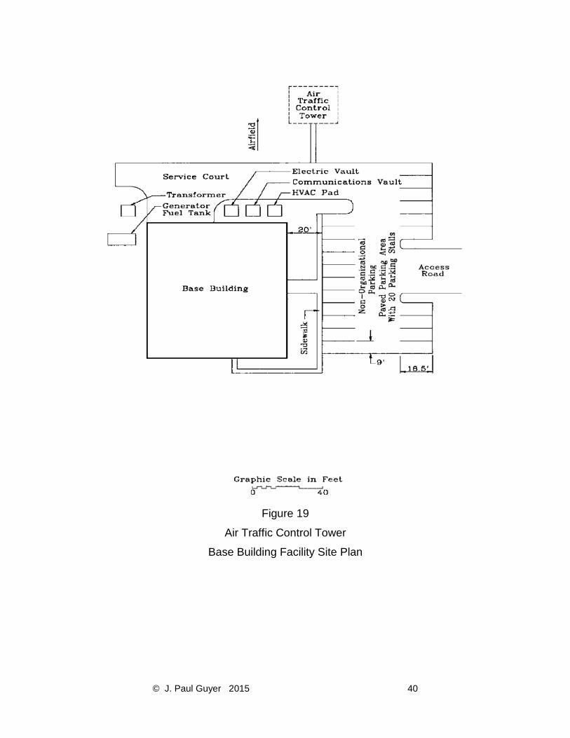
Figure 19
Air Traffic Control Tower
Base Building Facility Site Plan

© J. Paul Guyer 2015 41
Figure 20
Air Traffic Control Tower
Base Building Layout

© J. Paul Guyer 2015 42
Figure 21
Air Traffic Control Tower
Base Building Facility Design Notes

© J. Paul Guyer 2015 43
5.4.2 EMERGENCY ELECTRICAL POWER. Provide an emergency generator with
automatic starting and switching capability. Provide emergency power to the following:
a) Loads as required by NFPA-101.
b) Electronic equipment in IFR and terminal equipment rooms.
c) Building mechanical systems supporting electronic equipment.
d) Exterior security lighting and security systems.
5.4.3 400-HZ POWER. Provide 400-Hz power in accordance with Owner requirements.
5.5 LIGHTING. Provide dimmer adjustable red lights in IFR control room.
5.6 SECURITY. Air traffic control tower base buildings are normally located within
restricted areas which meet the minimum security measures for external security. If the
facility is located within a restricted area of a lower level of security, provide additional
measures to meet the minimum security requirements for the level of security assigned
to the facility. The level of security and the designer's responsibility for particular security
elements will be designated in the IDSEP. Refer to par. 2. Provide the following:
a) Electronic cipher door locks at interior entrance doors to IFR and terminal
equipment rooms.
b) Exterior doors in IFR and terminal equipment rooms with no access hardware on
the outside.
5.7 ADDITIONAL DESIGN CRITERIA. Refer to Section 2 for facility design requirements
not addressed above.