Embed Size (px)
Citation preview

An interactive design program for modular building elevations using an Apple II microcomputer Donald W Collins
This paper presents the history of MODBED (modular building elevation design), an architectural elevation design software package, describes its function and discusses the advantages of implementing similar software on new desktop computers (microcomputers) in answer to the design needs of small and medium-sized architectural and engineering offices. Local 'smart terminals' open the way to distributive processing and computer networking. These advancements can enhance decision making in the early stages of design and make it more cost effective.
microcomputer, architecture, drafting
In recent years, rapidly changing economic and environ- mental factors have impressed upon building industry pro- fessionals the need to save both time and money in developing new buildings and facilities. Although construc- tion costs are high and climbing fast, operation costs account for three-quarters of the costs incurred in the life- time of a building, and most of the decisions that affect the cost of operation of a building are irrevocably set by the time construction begins. These facts emphasize the great importance of the design phase of a building project which, by contrast, absorbs less than 1 per cent of the estimated life-cycle costs of a building 1-3 .
With the technological advances in building science and materials and the increasing size of modern projects, the design and building process has become more complex; it involves handling, processing and communicating vast amounts of information. This is an area where computer technology has progressed immensely. Thanks to the increased speed and storage capacity available in a low- cost package, microcomputers and computer networks promise to substantially improve the efficiency and pro- ductivity of the building design process. Now, the intro- duction of sophisticated graphics capabilities in desktop microcomputers has revolutionized the role of the com- puter in the building industry. It holds the promise of bold new applications in the design office. Clearly, the computer offers much more than the convenience of high-speed calcu- lations; it can become a versatile and sensitive medium for the designer's creativity and for the communication of ideas in visual form.
Centre for Building Studies, Concordia University, Montreal, Quebec, Canada
Computer graphics must be taken for what it is: a sophisticated modelling instrument that presents the designer with a swift rendition of what he sees in his mind's eye. The computer does not diminish the originality of the author but merely the time required to present a design. It does not 'package' overall designs but rather it allows the designer's creativity, the computer enables him to produce that goes into a feasible design. Far from threatening the designer's creativity, the computer enables him to produce and compare alternative designs quickly, accurately and economically.
In order to grasp the impact of computers (and micro- computers especially) on building design, one must under- stantd how the designer interacts with a terminal to pro- duce the design of his choice. We shall see this in detail with the help of an example.
MODBED is one of the first application packages to be implemented in the newly equipped Computer Aided Building Design (CABD) Laboratory at the Center For Building Studies, Quebec, Canada. MODBED is a user- oriented interactive program that handles architectural elevation design studies. Since it came into existence 12 years ago MODBED has undergone many transforma- tions, graduating from the batch processing mode in FORTRAN on a large expensive system, to time-sharing in BASIC, to a dedicated system with a specialized graphics language 4's and finally to its present form as an autonomous subsystem at an affordable cost.
The creation of GRASS (graphics symbiosis system) 6 , a specialized high-level graphics language, marked a turning point; the program was streamlined and the memory requirement plummeted from 67 kbyte to 24 kbyte. In its present form, the program now in BASIC, complete with the language package and the operating system, can be loaded into a standard desktop microcomputer such as the Apple II, requiring only 20 kbyte of its 48 kbyte of memory, the remaining memory being used for the design database.
MODBED" CASE HISTORY
As an application package for architectural design, MODBED proved itself: it produced design drawings faster than manual techniques while keeping the quality well within architectural standards 4 (see Figure 1 and Appendix). It also produced several data files relevant to other aspects of the design process, such as glass area, cladding area, material area and quantity rake-offs (see Table 1). These files could be used in the calculation of energy consumption, building
volume 15 number I january 1983 0010-4485/83/010025-08 $03.00 © 1983 Butterworth & Co [Publishers) Lid 25

" I1'" '" . , II,, , , l i , , I1,, l ,II , , I1 , , , tt
II , I l i , . . i l l , ' l l tJ , I1 , , , , I I , , , , t l , , , , , I1 , , ,
I I ' l l i ! ! , , , , l l ' l i . . ]11
" It , I1,, II, , ,
, I1,, II, l,~l I1,, tli , , . I | , , II, , , l l I1,, l i l l , , i i It, i I I , , , , l l IlJ, I I , , i II
If 11
I
II, II , , I1,, I1,,
li Figure 1. Drawing produced by MODBED
i l l l l l l l l
, , li , , ,
,,1[ , , ,
,,11 , ,'"r , i l l , , , I
i,,,,ll ,,
cost estimates and also by the contractor to establish con- struction bids. When a change was made in the design, all relevant files were updated automatically, eliminating the possibility of a change being omitted, which would other- wise cause expensive change-orders during the construction process. Dimension files for structural calculations and ver- tical circulation were also produced along with coordinate data for perspective drawings and shadow patterns. These files would eventually allow MODBED to be incorporated into an integrated design system called a MCSB (master control system for building) (see Figure 2).
Owing to the high cost of hardware and the fact that the implementation of new techniques in industry is an inherently slow process, MODBED was used mainly in the educational environment at first. The computer system, an IBM 370-135 with 132 kbyte of memory and a batch entry system, was to meet the needs of administration and faculty. This system precluded any direct interaction between the designer and the computer. The design data was entered onto a data-coding form, then punched onto cards and processed by the computer.
The resulting files were routed onto a high-speed printer, and the coordinate data was dumped onto a magnetic tape (or some other form of archival storage) which in turn was sent to a flatbed plotter. The plotter drew the actual design with a pen. The batch entry process isolated the designer from the computer, his work medium, and lacked flexibility since the turnaround on one design could be as long as 24 h. Furthermore, the nature of the input, numerical data on a form, robbed the designer of the vital function of visual representation. The initial cost of the equipment was absolutely prohibitive; for example, just the plotter used for MODBED, a flatbed Gerber Plotter, cost over $100 000 in 1969 not to mention the $0.5M for the computer.
What was significant about the original design of MODBED was not the cost, nor even the increased speed in the production of elevation drawings, but the fact that it was designed in a modular fashion using FORTRAN, a high-level language, which is itself nonmodular. The mod- ular form of MODBED ensured portability and proved to be useful when it was translated to other high-level languages to be used on other equipment.
When MODBED entered its second phase, about 1973, it was decided that the initial outlay costs for a building
design system had to be decreased if the program was to be well received. MODBED was implemented on a time-sharing PDP-11 minicomputer and a Xynetics flatbed plotter. To transfer MODBED to this computer with only 32 kbyte of memory, it was necessary to reprogram MODBED into RSTS/E BASIC, a language which allowed the program to be broken into modules and features-chaining capabilities and intraprogram variable retention. This is where the modular form of MODBED helped to make the imple- mentation on a smaller system a reality. In the PDP-11 version, although the program was spread out, it had all the information handling capabilities of the original IBM version.
The equipment cost approximately $125 000, but thanks to the time-sharing computer, it was possible to make the system available to several users, thus making it cost effective. This way, all the users could have access to a mass database of software, including MODBED, and have full control of the system without a large equipment investment. Presentations were made to several architectural design firms. The designers were not satisfied because they could not view the graphic output immediately, and had to wait too long for a revised print. Nevertheless, with respect to execution time, the machine output compared quite favourably with manual renditions and the designers were very impressed with the simplicity of the input and the quality of the output of MODBED (both graphic and numerical).
In its third phase, MODBED was to become a user- oriented interactive design package; a designer would be able to sit at a graphics station (a Vector General CRT),
Table 1. Sample of data produced by MODBED
Building Elevation Program TABLE 1 * * * * * * * * * * * * * * * * * * * * * * * * * * * * * * * * * * * * * * * * * * * * * * * * * * * * * * * * * * * * * * *
Architect . . . . . . . . . . . . . . . . . . . . . . . ACADZ Inc. 3624 Northcliffe Ave. Montreal, Quebec N4A 3K7 Canada
Project Name . . . . . . . . . . . . . . . . . . . . Project 8 2 0 4 2
Bank Building Elevation Test June 23, 1982
Material Brief .................................................
Total surface area of elevation ................. 5092.50 Total glass area for the elevation .............. 3469.38 Total cladding area for the elevation ........... 1623.38 Percentage of glass on the total surface ........ 68.13 Percentage Of cladding on t h e total surface ..... 31.87
Number of bays in the elevation ................. 5 Number of windows per bay ....................... 5 Number of floors in the elevation ............... 4
Total height of building ........................ 42.00 Total width of elevation ........................ 121.30
Total lineal footage of window jambs ............ 201.30 Total lineal footage of window mullions ......... 402.50 Total lineal footage of window sills ............ 341.25 Total lineal footage of window heads ............ 341.25 Total lineal footage of window transoms ......... 328.44
Total number of equal transom bottom panes ...... 75 Total number of equal transom top panes ......... 75
Material Breakdown by Floor - window frames ....................
Fl.to FI.* No.of*No.of * window frame lengths *
NO. NO.* bays *wind. * jamb * mull. * sill * head *transom*
1 1 * 5 * O * * * * * *
2 3 * 5 * 5 * 6.54* 6.54* 22.75* 22.75* 4.36* 4 4 * 5 * 5 * 7.04* 7.04* 22.75* 22.75* 4.36*
Material Breakdown by Floor - window glass .....................
Fl.tO FI.* window glass sizes * No. No.* jamb * mOdular * equal *
• ht. htt. wd. * ht. htt. wd. * ht. htt. wd. *
1 I* * * *
2 3 * * * 2.00 4.38 4.38* 4 4 * * * 2.00 4.88 4.38*
26 computer-aided design

Building optimization
• building codes
• zoning
Site Structural analysis
• traffic • live control loads
• circula- • dead tion loads
• floor • building • columns area location ratio
• volume • utilities • beams
• height • frames
• elevators • concrete
Graphics
• elevations
• plans •
• perspectives •
• details •
MCSB
Feasibility Mechanical Accounting Electrical Specifications study
• cost • heating • office • lighting • general analysis conditions
rental • ventilating • job • loads • governmental analysis requirements
investment • air • team • site work analysis conditioning
building • estimating • concrete type
• budget • masonry
• metals
Figure 2.. Master control system in building design
design his elevations interactively and review corrections to the graphics almost instantaneously. To obtain this level of interaction, it was necessary to reimplement MODBED in GRASS on the Vector General display and a completely dedicated PDP-11/45 minicomputer. The technology of the graphics required the host computer to be very near the graphics station. This eliminated the possibility of time-sharing and also raised the price to over $100 000, a level that only a few design organizations could afford.
The present MODBED system embodies the best of the above three phases, and incorporates microprocessor tech- nology. Nowadays, an interactive design station dedicated to one user and one application at a time represents an initial investment of less than $10 000 (less than the cost of a commercial word-processor). MODBED, which is used for elevation design, requires no foreknowledge of computer programming, only a knowledge of architectural terms. MODBED is an example, but any subsystem of Figure 2 can be implemented in the same way. Microcomputers pro- vide almost unlimited flexibility; a whole library of pro- grams can be compiled and stored on a two-disc system. By simply inserting the disc into the drive and calling up the program of his choice, the designer can study eleva- tions, plans, structures, energy requirements, project management, or estimating routines; the possibilities are almost infinite.
Microcomputer systems are manageable in size and com- pletely portable. For instance, the designer can actually take them to the construction site and have access to information on the mass storage disc system at the office. The microcomputer can also be connected to a larger com- puter system for transferring of files to and from the microcomputer (uploading and downloading, respectively). This is a tremendous advantage, because it optimizes the use of each system. For example, the larger computer can handle problems that require a lot of 'number crunching' and the microcomputer can process the results locally for a particular application.
This has been successfully accomplished in the CABD laboratory of CBS, MODBED's latest home. The laboratory features a Perkin-Elmer 3220 minicomputer with ¾ Mbyte of memory and two disc drives each with 67 Mbyte of storage. To date, the Apple II has been made to converse with the PE-3220 via a direct-line connection (RS232C) at 9600 baud, and with the university Cyber 174, via modem at 9600 baud. Furthermore, a simple interface now enables the Apple I1 to drive the ZETA plotter and
Tektronix plotter for hard copy output with no loss in resolution whatsoever.
Networking between the microcomputers, either by telephone (modem) or direct-line (RS232C), would allow the participants on a building project to communicate with each other rapidly and effectively. Networking would also attenuate hardware costs by sharing peripheral equipment. The selection of this equipment, which depends on the actual needs of the designers, may include a high-capacity fixed disc mass storage system, a high-speed printer, a printer/plotter and/or a pen plotter.
The long-range goal of the Center For Building Studies is to implement a completely integrated building industry database (MCSB) (see Figure 2). It would be built in a modular fashion, and expanded as other subsystems such as MODBED are added. As a result of their interaction, several subsystems working together on the same design project could create a project database by banking information of common value to all the participants to eventually reach the proportions of a building industry database. The PE-3220 minicomputer has the processing power and the memory capacity to manage the MCSB and the building industry database. The nine specialized laboratories in the Center will contribute research data to this database, particularly in the areas of acoustics, computer-aided building design, energy conservation and energy systems, lighting, project management, materials, prototype structures, structures and wind-tunnel.
Networking technology would allow the building industry database to be located in several different computer systems throughout the country, eliminating the risk of useless duplication of data. The only requirement at each local
database MCSB would be a directory of where other build- ing industry information could be accessed. Such a system would truly' be integrated.
The future of CABD lies in the direction of distributive processing with the introduction of microcomputers and computer networks. The goal of an integrated building industry database can only be reached with the cooperation of education, research, industry and government. This goal can be consolidated by sharing and updating information on both advancements in technology and on how best these advancements can be used by the building industry.
M O D B E D S Y S T E M
MODBED is a user-oriented interactive application program. It describes all elevation features in architectural terms, and
volume 15 number 1 january 1983 27

requires no particular programming skill since prompts, appearing on the video-screen, describe and control the execution of the program. The user can proceed as he wishes; he can execute the actual program in a straightforward manner, or refer back to the dataset outline to effect changes, or request a primer -- a point-by-point description of the design elements in MODBED complete with animated graphics and instructions. This the user can accomplish easily with the desktop convenience of a microcomputer like the Apple II.
Succinctly put, the MODBED program assembles modules according to the types, quantities and dimensions specified by the user and scales the overall design to a given factor. It performs predetermined calculations and organizes the results in numerical and coordinate data-files for sub- sequent use. Using MODI3ED, the designer can produce an endless variety of elevation model studies, or work to a degree of detail that is limited only by the resolution of the output equipment by simply varying some 15 parameters and the sequence of assembly.
The modularized architectural elements of an elevation design are facade-geometry, trusswork and window-config- uration. The three basic elevation types, flush, vertical and horizontal facade, are characterized by the intersection pattern of the column and beam cladding materials (see Figure 3). Three types of trusses are also defined: Pratt, Howe, and Whitney (Figure 4). They are sometimes used as transfer-trusses for horizontal stresses and their appearance is affected by the choice of facade. Window-configurations fall into four distinct categories governed by the window symmetry and the use of a transom-bar; they are namely: the modular plain, the equal plain, the modular transom and the equal transom window (see Figure 5). The choices may be extended with additional subroutines (submodules) for each new window type.
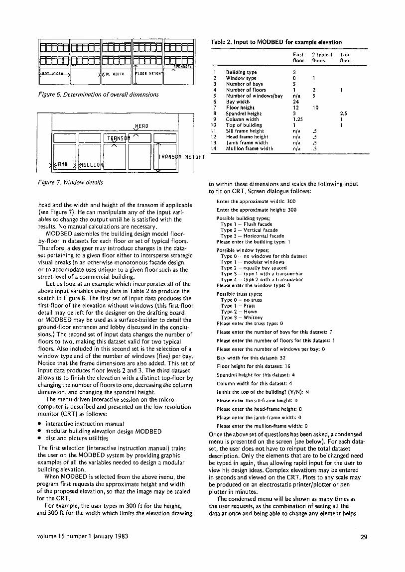
Overall vertical dimensions are determined by the number of floors, by floor and spandrel heights, overall
il ii JJ II
I I ....... II II il
1 I! II II I H H II
Figure 3. Basic elevation types (top) flush facade (middle) vertical facade (bottom) horizontal facade
lr--~"tl II 1! I NNVHVH i , , , , , , , , \ \ V
Figure 4. Truss types (top row) Pratt (middle row) Howe (bottom row) Whitney. Columns represent, left-to-right, flush, horizontal and vertical facades
I 1 I I I i
i 1 l t I I
rl n n Ir l~ I~
[ LJ
J H I H Figure 5. Window configurations (top to bottom) modular plain, type l O; modular transom, type 20; equal plain, type 11; equal transom, type 21
horizontal dimensions by the number of bays and by bay and column widths (see Figure 6). Combined with the building type, the above input can provide the designer with a basic structure elevation study. Otherwise, the designer can include the window type and dimensions to produce a more detailed elevation design which he can evaluate aesthetically. For this purpose, the designer only has to input the number of windows per bay with the following dimensions: the width of the jamb, mullion, sill,
28 computer-aided design
ts BIsB DrtD dDmDd
I °'°'" I / t ~ OL IIIDTH tLOOR I'IE]~GHt .SPRNDRI"L Figure 6. Determination o f overall dimensions
HEQD V
I II i " r r ~
#RMB ~ ~ULLIO TERNS
~f
Figure 7. Window details
HE GHT
head and the width and height of the transom i f applicable (see Figure 7). He can manipulate any of the input vari- ables to change the output until he is satisfied with the results. No manual calculations are necessary.
MODBED assembles the building design model floor- by-floor in datasets for each floor or set of typical floors. Therefore, a designer may introduce changes in the data- set pertaining to a given floor either to intersperse strategic visual breaks in an otherwise monotonous facade design or to accomodate uses unique to a given floor such as the street-level of a commercial building.
Let us look at an example which incorporates all of the above input variables using data in Table 2 to produce the sketch in Figure 8. The first set of input data produces the first-floor of the elevation without windows (this first-floor detail may be left for the designer on the drafting board or MODBED may be used as a surface-builder to detail the ground-floor entrances and lobby discussed in the conclu- sions.) The second set of input data changes the number of floors to two, making this dataset valid for two typical floors. Also included in this second set is the selection of a window type and of the number of windows (five) per bay. Notice that the frame dimensions are also added. This set of input data produces floor levels 2 and 3. The third dataset allows us to finish the elevation with a distinct top-floor by changing the number of floors to one, decreasing the column dimension, and changing the spandrel height.
The menu-driven interactive session on the micro- computer is described and presented on the low resolution monitor (CRT) as follows:
• interactive instruction manual • modular building elevation design MODBED • disc and picture utilities
The first selection (interactive instruction manual) trains the user on the MODBED system by providing graphic examples of all the variables needed to design a modular building elevation.
When MODBED is selected from the above menu, the program first requests the approximate height and width of the proposed elevation, so that the image may be scaled for the CRT.
For example, the user types in 300 f t for the height, and 300 f t for the width which limits the elevation drawing
Table 2. Input to M O D B E D for example elevation
First 2 typical Top floor floors floor
1 Building type 2 2 Window type 0 1 3 Number of bays 5 4 Number of floors 1 2 5 Number of windows/bay n/a 5 6 Bay width 24 7 Floor height 12 10 8 Spandrel height 3 9 Column width 1.25
10 Top of building 1 11 Sill frame height n/a .5 12 Head frame height n/a .5 13 Jamb frame width n/a .5 14 Mullion frame width n/a .5
2.5 t 1
to within these dimensions and scales the fol lowing input to f i t on CRT. Screen dialogue follows:
Enter the approximate width: 300
Enter the approximate height: 300
Possible building types; Type I - Flush facade Type 2 - Vertical facade Type 3 - Horizontal facade
Please enter the building type: 1
Possible window types; Type 0 - no windows for this dataset Type ] -- modular windows Type 2 - equally bay spaced Type 3 - type 1 with a transom-bar Type 4 - type 2 with a transom-bar
Please enter the window type: 0
Possible truss types; Type 0 - no truss Type I -- Pratt Type 2 -- Howe Type 3 -- Whitney
Please enter the truss type: 0
Please enter the number of bays for this dataset: 7
Please enter the number of floors for this dataset: 1
Please enter the number of windows per bay: 0
Bay width for this dataset: 32
Floor height for this dataset: t6
Spandrel height for this dataset: 4
Column width for this dataset: 4
Is this the top of the building? (Y/N): N
Please enter the sill-frame height: 0
Please enter the head-frame height: 0
Please enter the jamb-frame width: 0
Please enter the mullion-frame width: 0
Once the above set of questions has been asked, a condensed menu is presented on the screen (see below). For each data- set, the user does not have to reinput the total dataset description. Only the elements that are to be'changed need be typed in again, thus allowing rapid input for the user to view his design ideas. Complex elevations may be entered in seconds and viewed on the CP, T. Plots to any scale may be produced on an electrostatic printer/plotter or pen plotter in minutes.
The condensed menu wil l be shown as many times as the user requests, as the combination of seeing all the data at once and being able to change any element helps
volume 15 number 1 january 1983 29

I I I I I I I I I I I I I I I I I I I t i l l I t l l l l l l I l t t I l l l l l l l l l l I l l l I l l l I l l
Figure 8. Drawing produced from data in Table 2
I se t i
the designer to design an elevation. Screen dialogue follows:
MODBED
1 Building type: t 2 Window type: 0 3 Truss type: 0 4 Number of bays: 7 5 Number of floors: 1 6 Number of windows per bay: 0 7 Bay width: 32 8 Floor height 16 9 Spandrel height: 4
10 Column width: 4 11 Top of building: 0 12 Sill height: 0 13 Head height: 0 14 Jamb width: 0 15 Mullion width: 0 16 Transom-frame height: 0 17 Transom height finish fl.: 0
Are there any values that you wish to change for this dataset: N
After the user has answered the above question with no (N), signalling that he has completed all modifications, the program will draw the portion of the building elevation des- cribed by that dataset on the CRT or plotter, depending on the output option selected (se c Figure 9).
The user may return to the menu by pressing the space bar. This will allow him to make modifications to the input data for the second dataset, in continuing the design. For example, if the user wanted to change the number of floors (variable 5) to two, the number-of-floors variable on the menu above would be changed to the new input, ie 2. He may select a window type of three for the second vari- able which would give him modular transom windows in each of the seven bays. Once the window type is selected, the user must define how many windows per bay
(variable 6), and input the window-frame dimensions in variables 12 to 16. The height of the transom-bar is input as variable 17 (see above menu of MODBED). This change would become the second dataset and would look like Figure I0.
The user returns to the menu by pressing the space bar again to continue the design. He changes variable 10 (the top of the building on the above menu) which controls the flow of the program as a flag by allowing the user to add on more floors if the variable is set to 'NO/0'. Once a 'YES/I ' value has been assigned to variable 10, the program will then top-off the building and draw a ground-line (see Figure 11 .) If, in this dataset, the user does not change any other variables, two more floors of the same data will be drawn giving a five-storey elevation as can be seen in Figure 1 I. Once the elevation is complete, the user has the option of either saving the coordinate data of the eleva- tion onto a floppy disc (using the util ity routine in the first menu), or doing another elevation.
The designer may save the completed graphic file on disc storage for later review. While the microcomputer is pro- ducing the graphic on the CRT, it calculates material quan- tities and compiles dimension and coordinate data, which could later be used in an integrated building design system (see Figure 2 and Table I.)
CONCLUSIONS
Modern microcomputer technology has produced a genera- tion of machines with a high degree of autonomy and powerful built-in functions. Yet, the use of these micro- computers is well within the grasp of the common user. The implementation of MODBED, an architectural-application" software package on the Apple II, has conclusively demon- strated the versatility and the adaptability of this class of computer to either the small design office mindful of its budget or the large firm. The microcomputer is well suited to the wide variety of work settings in the building industry at large because, as a single workstation, it provides local intelligence; it can also be networked to a larger computer or to other micros using a direct-line hook-up (R5232C) or a modem, and finally, it can easily be interfaced with a whole range of peripheral devices.
I [ tl I II ............... rl Figure 9. Ground f l o o r - first graphic screen displayed
! !/ II ]1 I
l tf ........ ]J __ll tl Jl Jl I Figure 10. Ground, first and second floors - second graphic screen displayed. The data set includes window information for two typical floors as well as the first floor
30 computer-aided design

p ,u RF] GLT-n
1 t ............. i I II r
N! i: !LI i! {! U
P qJ P,! ! H ! ! ! Hi ,, ! ! ~ , ~! ! ! !!M I II 11 I
Figure 11. Completed elevation - third graphic screen displayed. The only change to the previous data set menu was to select the top o f the building which sets the flag to finish the building. I t also draws two typical floors because the number o f floors was not changed.
The research work has now extended the use of MOD BED as a surface building algorithm to be used for the following MSCB modules:
• Building Perspective
o new o existing o block layout for rendering o hidden line o hidden surface
• Building Plans
o floor o ceiling o bathroom tiles
• Quantity Data
o cost-estimating o life-cycle costing o energy design envelope and energy system
• Structures
o dimension-file for structural analysis
• Lighting
o envelope for natural lighting o ceiling grids
• Acoustics
o envelope quantity data
Office, Washington, DC, USA PB-283 306 (11 July 1979) p12
2 Russell, A D Building Economics - Course Notes Centre for Building Studies, Concordia University, Canada 1979
3 Russell, A D and Choudhary, K T 'Cost optimization of buildings' ASCE J. Struct. Division (January 1980) pp 283-300
4 Collins, O W 'A computer graphics system for modular building elevation design' 51GGRAPH '75 Proc. Comput. Graphics Vol 9 No I (Spring 1975) pp 137-147
5 Collins, D W 'Rote des graphiques produits par ordinateur dans la conception des batiments' L 'lngenieur No 338 (September/October 1980)
6 Defanti, T A Dissertation, Ohio State University, OH, USA (1973)
APPENDIX Below and on the following page are some examples of drawings produced using MODBED. The drawing below was completed with two interactions with the menu for the base and six interactions for the tower. The first drawing overleaf required only four interactions: lobby floor, first spandrel panel, 20 typical floors and top floor.
These modules are presently being integrated by the graduate students in the Computer Aided Building Design Laboratory supervised by a multidisciplined faculty of the Center for Building Studies here at Concordia University, Quebec, Canada.
ACKNOWLEDGEMENTS
The work outlined in this paper has been made possible by a grant-in-aid from the National Sciences and Engineering Research Council of Canada, Grant no. A1172. The author wishes to acknowledge the assistance of Charles Gibson and Michel Tremblay in the production of this paper.
REFERENCES
1 Computer Aided Building Design General Accounting
I ' : : I I i i i l l . l J i l : i i l ! . . . ! i i 1 1 1 ! . . ' . ! i i i i i [ l l i l
i i :! k o , , t
I . , ! : 4 i l l l l
iL , tl , , , , i i u ,
volume 15 number 1 january 1983 31