Embed Size (px)
Citation preview
1
An inter-balloon data relay using Software Defined
Radios: Paving the way for distributed space systems
I. Lluch, R.Akhtyamov, H. Matevosyan, D. Knoll, U.Pica, V. Chulkov The Mobile Networking for Space Technology Experimental Research team (MONSTER)
Skolkovo Institute of Science and Technology 100 Novaya str., Skolkovo, Moscow Region.
Russia 143025. +7 925 0571504 [email protected]
TABLE OF CONTENTS
1. INTRODUCTION ............................................. 1
2. EXPERIMENTAL APPROACH ........................... 1
3. CAMPAIGN RESULTS ...................................... 3
4. FUTURE WORK AND CONCLUSIONS ................. 5
5. REFERENCES ................................................. 5
1. INTRODUCTION
The emergence of novel distributed space system concepts, such as federated satellite systems [1] and fractionated spacecraft [2] poses new challenges on space communications and networking technologies. In order to support space mission de-centralization and cooperation among heterogeneous spacecraft [3], flexible and reconfigurable solutions are required.
This report presents a flight test of a Software Defined Radio (SDR) [4] implementing a high-altitude data relay. Software defined radios were introduced in the 90’s [5] with the idea of using computer code as means to configure and operate radios. By using Digital Signal Processing (DSP) techniques, SDRs can modify, even dynamically, their modulation, coding, encryption and Radio Frequency (RF) front-end characteristics. This makes SDRs a key technology for future space distributed systems, enabling physical and media access layers interoperability between spacecraft with diverse RF communications systems.
SDRs are already gathering strong interest in the space communications and networking domain [6] due its inherent flexibility and potential for spectrum decongestion. The Aerocube 3-U Cubesat [7] is the most recent mission including a custom SDR prototype, which brings SDRs to small satellite missions [8]. The advent of such small missions, frequently deployed by actors with limited means, time or expertise -like universities- demands for the use of inexpensive, widespread technologies and commercial off-the-shelf (COTS) components. COTS SDRs have found hobbyist applications as satellite ground receivers, but the experiment presented here, is, to the best of our knowledge, the first system successfully employing a COTS SDR hosted in and single-board computer to operate a link an aerospace environment.
Nowadays, there are several COTS SDRs available in the market. The last decade has seen the rise of affordable SDR boards including the USRP N210, ZeptoSDR, HackRF and BladeRF [9].
The experiment described herewith deployed a BladeRF, an inexpensive SDR, on two stratospheric High Altitude Balloons (HABs) and a tracking ground station (GS). The goals were two-fold. First, to characterize the long-range performance of COTS SDRs when deployed in a relevant aerospace environment [10]. The second goal of the experiment described here was to provide a proof of concept for SDR-based space data relay, partially implementing the space communications protocol proposed for Federated Satellite Systems [11].
The next section describes the experimental approach chosen to fulfill this work’s goals. Then, the campaign results are presented. In the last section, conclusions are drawn and the future work is outlined.
2. EXPERIMENTAL APPROACH
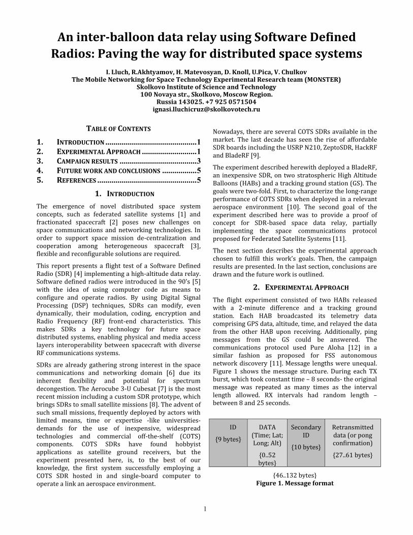
The flight experiment consisted of two HABs released with a 2-minute difference and a tracking ground station. Each HAB broadcasted its telemetry data comprising GPS data, altitude, time, and relayed the data from the other HAB upon receiving. Additionally, ping messages from the GS could be answered. The communications protocol used Pure Aloha [12] in a similar fashion as proposed for FSS autonomous network discovery [11]. Message lengths were unequal. Figure 1 shows the message structure. During each TX burst, which took constant time – 8 seconds- the original message was repeated as many times as the interval length allowed. RX intervals had random length – between 8 and 25 seconds.
ID
{9 bytes}
DATA (Time; Lat; Long; Alt)
{0..52 bytes}
Secondary ID
{10 bytes}
Retransmitted data (or pong confirmation)
{27..61 bytes}
{46..132 bytes} Figure 1. Message format

2
Additionally to the high-level message format shown above, the framing operations were performed in GNU Radio. The software transmitter added a preamble, an access code and pads Cyclic Redundancy Checks / End of File (CRC/EOF) after the main message, as well as whitening (for randomizing bits). On the receiving end, the receiver performed the same operations in reverse order, with an extra correlator used for identifying the access code of the message [13].
The ground station’s directional antenna was capable of pointing at one of the HABs and track it by using the transmitted GPS telemetry, completing a 3-node network as shown on Figure 2.
Figure 2. Network concept experiment showing the real flight altitude profiles followed by the HABs.
Figure 2 illustrates the experiment setup together with the real flight altitude profiles of the two HABs. The SDR systems and all other equipment–the platform- hanged within a foam container 15m below the HABs. The next section describes the equipment on the platforms, which were identical for both HABs.
Platform Subsystems
Each HAB platform was composed of five subsystems besides the main payload: sensor bus, imaging subsystem, independent recovery subsystem, power subsystem and structure subsystem. Figure 3 depicts these component subsystems and their interfaces.
The recovery subsystem and imaging subsystem were autonomous and functionally independent to the main payload. The centralized power bus supplied stabilized voltage to the rest of the subsystems. The sensor bus shown below was controlled by an Arduino and provided for autonomous logging of GPS and 10 Degrees Of Freedom (DOF) sensor data, together with a GSM system that sent text messages with GPS data, acting as a backup recovery system.
The Sensor bus constantly sent sensor data to the main payload. The subsystems described above were held on a double-decked wooden board and installed within a box-shaped foam shell.
The subsystems described in this section gathered flight data and supplied power to the Main Payload, which the next section portrays.
Figure 3. Platform Subsystems

3
Main Payload: SDR and RF chain
The SDR system was based on a BladeRF x115 commercial off-the shelf SDR. Technical characteristics of this board can be found on [9].
The BladeRF was operating with Raspberry Pi 2 (RPi2) as a host computer. The RPi2 read the data from the sensor bus as shown on Figure 3, formatted the messages and implemented the media access layer of the network. Then it exchanged IQ-streams (In phase and Quadrature components) with BladeRF and performed the signal processing via GNU Radio.
The RPI2 hosted two independent TX and RX scripts, which were executed sequentially and timed within a randomized window interval to avoid constant collisions with messages from the other nodes in the network. In order to operate in half-duplex mode with a single antenna, the RPi2 controlled a RF switch that channeled either the TX or the RX side of BladeRF onto the omnidirectional antenna. The RF chain was completed by a 0.5 W-rated power amplifier and a ground metal baseplate to improve the performance of the omnidirectional monopole [14]. Figure 4 shows the main payload, the sensory bus and the power subsystem mounted on the deck.
Figure 4. The inferior (left) and superior (right) decks of
the platforms with the main payload, the sensory bus
and the power subsystem mounted. BladeRF SDR is on
the bottom left.
Ground station
The ground station side also consisted of a BladeRF and a RF chain analogous to the one on the platforms, substituting the RPi2 by a laptop running GNU Radio. The Ground station antenna was a 5 element Yagi (providing aprox. 9 dBi gain) mounted on an azimuth – elevation tracking mount.
Radio link parameters
The link parameters are shown in Table 1. The link was placed on one channel within amateur band for convenience. The flight campaign was conducted in the territory of the Russian Federation and great care was
placed into being compliant with local radio regulations, which limit the bandwidth and the power to those shown in Table 1. The available bandwidth was the limiting factor for the link data rate and the driving constraint for the choice of half-duplex instead of full-duplex operations.
Table 1. Radio link parameters for the radio experiment.
Central Frequency, MHz 446.043750
Bandwidth, Hz 12500
Modulation GMSK (BT = 0.35)
Radiated Power, W 0.5
Data rate 3.3 kbit/s
3. CAMPAIGN RESULTS
The launch of the two HABs (HAB1 and HAB2) was conducted 200 km southeast of Moscow at (39.8004, 55.2992), on April 21, 2015, between 13:00 and 13:15 local time. The maximum altitudes during the flight were 32 and 31 km and the flight total ground distances were 104 and 95.3 km for HAB1 and HAB2, respectively. Both HABs were successfully recovered after a flight time of 2h 30 minutes for HAB1 and 2h 40 minutes for HAB2. In order to characterize the performance of the radio links, the raw IQ-data received during the flights was recorded. This section analyzes the data after processing via GNU Radio.
The retrieval of in-flight data allowed the evaluation of the signal-to-noise ratio (SNR) achieved during flight through the analysis of the envelope of the signal. Three two-way links were present in the test flight, that is, HAB1 link to the Ground Station (GS), HAB2 link to the GS, and the inter-balloon link. The latter is treated independently, as the HAB1 (TX) to HAB2 (RX) and the HAB2 (TX) to HAB1 (RX) links. The SNR of these links naturally evolves with the slant ranges involved, as shown on Figure 5 and Figure 6.
Figure 5. Signal to noise ratio (SNR) as a function of
slant range for the HAB2 to GS link, and for one
direction of the inter-balloon link.
Antenna pointing error
HAB2 Landing

4
HAB2 was actively tracked from the ground with a directional antenna as described in the previous section. The HAB2 - GS link was operational through the whole flight and achieved a final slant range of 91km. On the first 30 km the antenna tracking system experienced a pointing error related to the coordinate system transformation, which lead to a dip in SNR, which was later corrected by mission operations. Notwithstanding this error, contact was never lost with the in-flight balloon network, providing continuous operations. The antenna pointing error interval is marked on Figure 5 for clarity.
Approaching the landing moment, the HAB2-GS link was lost due the low elevation angle (<3 degrees). This forced the link through elevated terrain and foliage obstacles. However, when the loss of link occurred, the SNR still had a 10 dB margin, showing that in absence of obstacles, and notwithstanding bandwidth and transmit power limitations required to comply with local regulations, SDR-based COTS communications equipment could provide data links at ranges relevant for aerospace applications.
Another network link shown on Figure 6 is the HAB2 (TX) to HAB1 (RX) link. This link experienced a varying range from 0 to 15 km, subject to wind conditions. The SNR is smaller than for the ground link as the inter-balloon link solely employed monopole antennas.
Figure 6. Signal to noise ratio (SNR) as a function of
slant range for the HAB1-to-ground link, and the HAB1
to HAB2 link.
The HAB1 was not actively tracked during the flight, therefore the SNR of the HAB1 to GS link quickly dropped, as shown in Figure 6. Additionally, HAB1 experienced an in-flight partial failure on the RF chain attributed to a wiring misconnection. This led the RF switch to stall in failsafe RX mode with which reception of data was still possible, yet suffering 20 dB attenuation on the channel. This attenuation is clearly shown in Figure 6, where the SNR of the inter-balloon link between HAB1 (TX) to HAB2 (RX) decreases sharply. Ultimately, the anomaly led to the early loss of the link from the HAB1 to the ground station after 15 minutes in
flight and 11 km range, as shown above. Nevertheless, the ground station was still able to retrieve HAB1 data in real time through the inter-balloon link, for which HAB2 operated as a relay for 45 minutes in flight and up to 4 km range, uninterrupted. This is actually a successful proof of concept for federated satellite systems, showing how a partial system failure does not hinder the operations of the participant missions thanks to the networked approach. HAB1 signal was not able to reach the Ground Station, but HAB2 was in a closer range and relayed its data.
In addition to the SNR, the quality of the channel has been characterized by the amount of messages received and collided. In the designed system, each transmission burst contained repetitions of the original message. The chosen Pure ALOHA protocol determined the performance of the inter-balloon link. In the balloon network, RX intervals were randomized; therefore the number of messages to be received necessarily was varying. Figure 7 illustrates these effects through the flight time.
Figure 7. Number of HAB2 messages per TX interval received by ground station and by HAB1.
The performance of the Pure ALOHA protocol significantly depends on data-rate, packet-generation rate, and packet length. The scope of this test did not include an optimization of those, so significant amount of data collisions took place in the network. 53% of messages originated in HAB1 were relayed with integrity through HAB2 to the ground station, whereas for the direct HAB to ground links this value was close to 100%. 63% of messages originated in HAB2 (TX) were received in HAB1 with integrity, while the value is close to 30% for the return link due the issues described before. However the intended data links and relay were successfully established; the next section discusses the future improvements and outlines the results obtained.
* 45th minute of operations: lost inter-balloon link
* 15th minute of operations

5
4. FUTURE WORK AND CONCLUSIONS
This report presented the implementation of a COTS SDR-based RF link in a high altitude balloon network, as means to test and characterize the long-range performance of this key technology for future space distributed systems. In particular, SDRs hold the promise to provide communications inter-operability for novel space architectural paradigms such as Federated Satellite Systems. This report showed how an inexpensive system based upon Nuand's BladeRF and Raspberry Pi 2, and GNU Radio on the software side, can succesfully establish links at more than 90km distance with a graceful SNR degradation, and a margin larger than 10 dB. Pending additional flight tests, and a characterization of radiation tolerance of hardware components of the system, the communications system presented in this report could be deployed on small satellites, CubeSats and any cost-constrained space assets, where they can provide flexible solutions for the reuse of the RF spectrum, and enable mission interoperability. Along with the COTS SDR long range test, the data relay between two mobile, high altitude nodes served to illustrate the federated satellite systems concept. This approach significantly increased the general reliability of the system: partial failure of single components was overcome by the networked approach. This is a characteristic feature pursued by Federated Systems.
Future work includes optimizing the link parameters of to reduce message collisions, moving the project from proof of concept to performance optimization. Incoming flight tests shall also include more nodes to probe the performance of the proposed FSS protocol [11] at the network layer.
COTS SDRs are nowadays widely used in amateur contexts to receive satellite radio downlinks. However, this report presents a novel usage of COTS SDRs with single-board computers to perform communications relay on a mobile, aerospace application. Moreover, this is the first flight to test key technologies for the federated satellite systems concept. This work supports the consolidation of this new distributed space mission paradigm and pushes forward the research to make future space missions more sustainable, reliable and cooperative.
5. REFERENCES
[1] A. Golkar and I. Lluch Cruz, “The Federated Satellite
Systems paradigm: Concept and business case
evaluation,” Acta Astronautica, vol. 111, no. 0, pp.
230 – 248, 2015.
[2] Y. Nakamura, N. Faber, D. Mauro, S. Ghaffarian, R.
Alena, C. R. Frost, G. Bhat, and J. McNair,
“Heterogeneous Spacecraft Networks: Performance
analysis for low-cost Earth Observation missions,” in
Aerospace Conference, 2014 IEEE, 2014, pp. 1–14.
[3] Owen Brown and Paul Eremenko, “The Value
Proposition for Fractionated Space Architectures,” in
Space 2006, 0 vols., American Institute of
Aeronautics and Astronautics, 2006.
[4] J. H. Reed, Software radio: a modern approach to
radio engineering. Upper Saddle River, NJ: Prentice
Hall, 2002.
[5] J. Mitola, “Software radios-survey, critical evaluation
and future directions,” 1992, pp. 13/15–13/23.
[6] M. J. Crowne, C. B. Haskins, R. E. Wallis, and D. W.
Royster, “Demonstrating TRL-6 on the JHU/APL
Frontier Radio for the Radiation Belt Storm Probe
mission,” 2011, pp. 1–8.
[7] E. Grayver, A. Chin, J. Hsu, S. Stanev, D. Kun, and
A. Parower, “Software Defined Radio for Small
Satellites,” 2015, pp. 1–13.
[8] M. R. Maheshwarappa and C. P. Bridges, “Software
defined radios for small satellites,” 2014, pp. 172–
179.
[9] O. Hazarika and A. Mishra, “A Review of Hardware
Platforms for Whitespace Communication,” in White
Space Communication, A. K. Mishra and D. L.
Johnson, Eds. Springer International Publishing,
2015, pp. 33–48.
[10] A. Nayak, A. G. Sreejith, M. Safonova, and J.
Murthy, “High-Altitude Ballooning Program at the
Indian Institute of Astrophysics,” ArXiv e-prints, Feb.
2013.
[11] I. Lluch, P. T. Grogan, U. Pica, and A. Golkar,
“Simulating a pro-active Ad-Hoc network protocol
for Federated Satellite Systems,” 2015, pp. 1–13.
[12] R. Rom and M. Sidi, Multiple access protocols:
performance and analysis. New York: Springer-
Verlag, 1990.
[13] F. Ge, C. J. Chiang, Y. M. Gottlieb, and R. Chadha,
“GNU Radio-Based Digital Communications:
Computational Analysis of a GMSK Transceiver,” in
Global Telecommunications Conference
(GLOBECOM 2011), 2011 IEEE, 2011, pp. 1–6.
[14] S. Abootorabi, M. Kaboli, S. Mirtaheri, and M.
Abrishamian, “Using high impedance ground plane
for improving radiation in monopole antenna and its
unusual Reflection phase properties,” in PIERS
Proceedings, 2009, pp. 197–201. [15] C. Morris, A. Baker and P. Cary, “software defined
radio for the Wright State University high altitude
Balloon Team,” Tech. Rep., 2011.
*Launch day pictures, captures from the balloon and GPS strings were delivered in a compressed folder with this report.