Embed Size (px)
Citation preview

An Intelligent Control of Three-Phase Distributed Power Flow
Controller for Power Quality Improvement
*Rajarathinam P1 and Vijayakumar G2 1(Research Scholar, Anna University), Principal, Dept. of EEE, Adhiyamaan
Polytechnic, Hosur, T.N., India, 2Associate Professor in the Department of Electrical Engineering at Muthayammal
Engineering College, Rasipuram, T.N., India, 1Email: [email protected]
2Eemail: [email protected]
Abstract: This paper illustrated the harmonics elimination in the line current using
intelligent control technique based Distributed Power Flow Controller (DPFC) for
injecting compensating current to the transmission lines. Voltage fluctuations is
caused in transmission lines by non-linear loads, abrupt load conditions, which
results in reducing the usage of distributed system. A simple shunt and series 3 arm
converters are used in making the Distributed Power Flow Controller. To control
and regulate the voltage through the DC link capacitors, Fuzzy Logic Controller
(FLC) is executed. Using the propounded method, line harmonics is terminated by
injecting compensational current reference which handles the reactive power
requirement for dynamic load conditions.
Keywords: Distributed Power Flow Controller, fuzzy logic controller, Active Power
Flow, Total Harmonic Distortion
1. Introduction:
The harmonic content in the consumer end of ac mains is increased by the
impact of abrupt loads in the power grid. Generally, AC electric loads are non –linear
loads. The poor power factor and poor efficiency in the utility side is maintained due
to the harmonics and excessive reactive power in the transmission line. A bulky
component size and occurrence of resonance is introduced by the passive filters are
widely used in the transmission line for harmonic reduction and improving power
factor. Some advantages like less response time and better performance than the
active power filter (APF) [1] – [3]. The main source for producing the harmonic
contents in the power network are power electronic device and non linear load which
damages the quality of power. The line harmonics due to non-linear load compensated
by shunt converter by injecting compensation current to the grid line which has the
merits of control ability and quick response and line voltage can be compensated by
shunt converter. An effective approach the suppress the harmonic pollution can be
done by inhibiting the flicker and compensating reactive power.
Line harmonics leads to poor distribution system utilization factor by the non-
linear load. Using series and shunt converters, the harmonics in transmission lines are
suppressed. The recommended levels of harmonics are not affecting the function of
electrical gadgets from high voltage. Low power factor and overheating is occurred
by large and a massive resonance effect. A reference current is generated by shunt
converter based on the types of load and load current. For neutral line compensation
Tierärztliche Praxis
ISSN: 0303-6286
Vol 39 Issue 10 October - 2019
108
active power filter are used rarely. Hysteresis current control and adaptive control
methods are some of the conventional control methods which can only be used to
certain extend and then involve a complex theory. A highly structured control
particularly in terms of robustness is needed for using of non-linear loads and three
phase unbalanced loads. To decide the compensation current to be injected by shunt
converter in to line one of the harmonic detecting and eliminating method with rapid
reactive power compensation theory is considered to be useful.
Shut converter is more potent for medium and high voltage application rather
than large transformers and passive filters to diminish reactive power, to improve
power factor and to accomplish sinusoidal source current a series of reactive power
compensators are suggested. The compensation characteristics are influenced by the
selection of the control strategy for Distributed Power Flow Controller (DPFC) [4].
Total Harmonic Distortion (THD) of source current is increased by increase in power
factor under distorted supply of voltages. The unity of power factor is not provided by
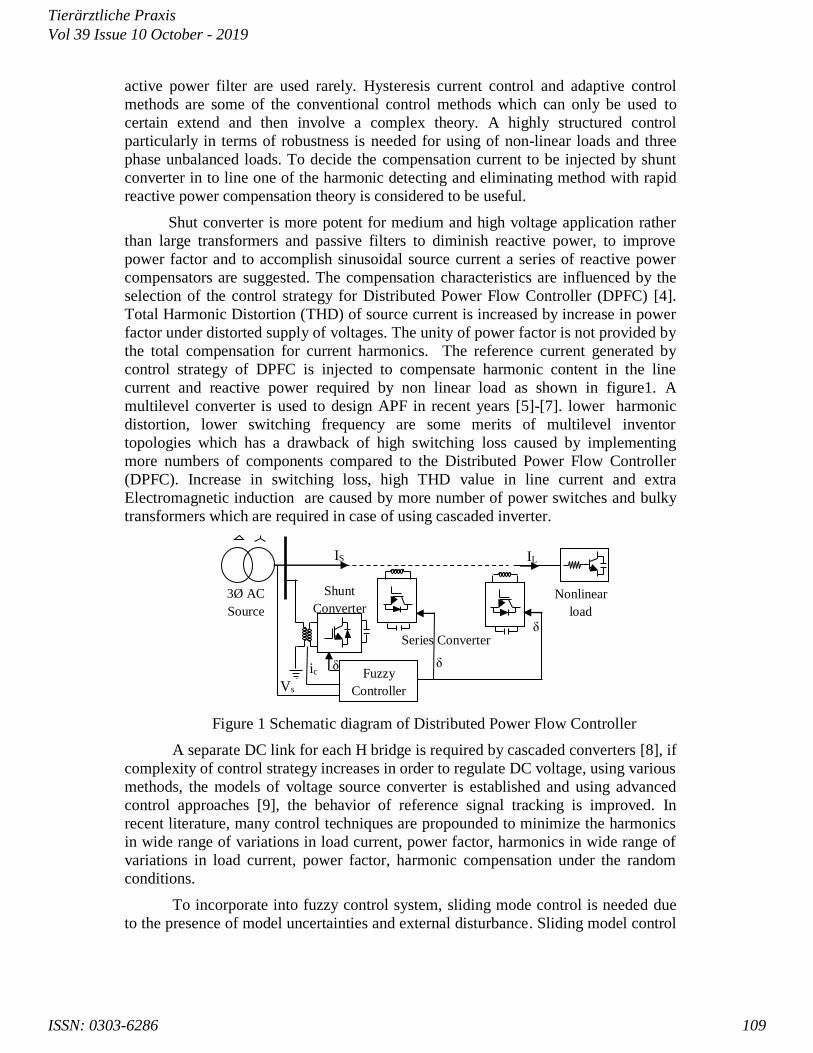
the total compensation for current harmonics. The reference current generated by
control strategy of DPFC is injected to compensate harmonic content in the line
current and reactive power required by non linear load as shown in figure1. A
multilevel converter is used to design APF in recent years [5]-[7]. lower harmonic
distortion, lower switching frequency are some merits of multilevel inventor
topologies which has a drawback of high switching loss caused by implementing
more numbers of components compared to the Distributed Power Flow Controller
(DPFC). Increase in switching loss, high THD value in line current and extra
Electromagnetic induction are caused by more number of power switches and bulky
transformers which are required in case of using cascaded inverter.
Figure 1 Schematic diagram of Distributed Power Flow Controller
A separate DC link for each H bridge is required by cascaded converters [8], if
complexity of control strategy increases in order to regulate DC voltage, using various
methods, the models of voltage source converter is established and using advanced
control approaches [9], the behavior of reference signal tracking is improved. In
recent literature, many control techniques are propounded to minimize the harmonics
in wide range of variations in load current, power factor, harmonics in wide range of
variations in load current, power factor, harmonic compensation under the random
conditions.
To incorporate into fuzzy control system, sliding mode control is needed due
to the presence of model uncertainties and external disturbance. Sliding model control
Vs
Shunt
Converter 3Ø AC
Source
Fuzzy
Controller
Series Converter
ic δ
IS IL
δ
δ
Nonlinear
load
Tierärztliche Praxis
ISSN: 0303-6286
Vol 39 Issue 10 October - 2019
109

[10] is a robust control technique with many attractive features like robustness to
parameter variations [1], [11] and the tracking capability of switching surface. But
systematic stability analysis and controller design of fuzzy logic control with
application to shunt and series converters [12] are not found in literature. Therefore, it
is necessary to adopt intelligent control technique such as Fuzzy Logic Control that
can be adjusts automatically to control system parameters for the harmonic
elimination of proposed converter.
2. Proposed Control Scheme
Reference power is generated; Compared with a reference set value, a
reference voltage is generated by the dc link capacitor voltage of DPFC. By the
resulted error value and with change of error value by fuzzy controller which
regulates the DPFC through the reference current generator. In figure 2, fuzzy logic
control structure of proposed DPFC is given.
1
Ploss
-K-
e
-K-
ce
z
1
Unit Delay
Fuzzy Logic
Controller850 Constant
1
Vdc
Figure 2.Fuzzy Logic Controller Simulink Model
A reference current is generated by sensing the load current and source
voltage to the current controller by rapid active and reactive power theory (P-Q
theory) [5] . The preset reference value is compared to the original filter current to
give the gate pulse to the voltage source inverter (VSI) by the hysteresis controller.
The VSI output flows through the active filter to the line which draws an unwanted
harmonics from the line. As a result, the line current harmonics can be eliminated,
compensate the reactive power and improvement of power factor can be achieved.
Fuzzy logic method uses input and output membership function whose values
are varies between 0 and 1. Problems having vagueness uncertainty or imprecision are
specially dealt by fuzzy logic methods rather than Boolean or crisp logic. Human
control logic is replicated by fuzzy, one of the best proved method for many system
applications. To estimate the power loss of active power filter the DC link voltage is
regulated .The original capacitor voltage is compared with a set of reference value.
Using fuzzy logic controller (FLC), the error signal generated from the comparator is
processed. In tracking the Iref fuzzy sets are chosen, based on the error in the DC link
voltage, in which FLC contributes to nearly zero steady error. A 7X7 membership
function is considered, {NE (negative extreme), NM (negative middle value), N
(negative), Z (zero), PS (positive), PM (positive Middle), PE (positive extreme)} are
used for the flexibility of program for input and output membership functions. In the
figure 3-6, input and output membership functions are used in fuzzy interference
system (FIS) and surface view are given.
Tierärztliche Praxis
ISSN: 0303-6286
Vol 39 Issue 10 October - 2019
110

Figure 3 Input Membership Function _ Error (e)
Figure 4 Input Membership Function _ change in error (Δe)
Figure 5 Output Membership Function _ (u)
A rule base is constructed to manage the output variable, in fuzzy logic control
method. A simple IF-Then rule with a predetermined condition was constructed. The
rules that relate the input variables to the output variable are defined by the design of
fuzzy control rule. The input of FLC is an error (e) and change in error (Δe) value of
capacitor dc voltage and the output (u) of the fuzzy is power requirement (Ploss) for
the voltage regulation. The control rule shows input and output Table1.
Tierärztliche Praxis
ISSN: 0303-6286
Vol 39 Issue 10 October - 2019
111
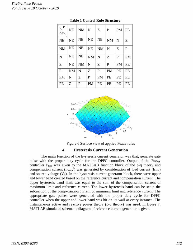
Table 1 Control Rule Structure
e
Δe NE NM N Z P PM PE
NE NE NE NE NE NM N Z
NM NE NE NE NM N Z P
N NE NE NM N Z P PM
Z NE NM N Z P PM PE
P NM N Z P PM PE PE
PM N Z P PM PE PE PE
PE Z P PM PE PE PE PE
-1-0.5
00.5
1
-1
0
1
-0.4
-0.2
0
0.2
0.4
ece
u
Figure 6 Surface view of applied Fuzzy rules
4. Hysteresis Current Generation
The main function of the hysteresis current generator was that; generate gate
pulse with the proper duty cycle for the DPFC controller. Output of the Fuzzy
controller Ploss was given to the MATLAB function block of the p-q theory and
compensation current (IComp*) was generated by consideration of load current (ILoad)
and source voltage (VS). In the hysteresis current generator block, there were upper
and lower band created based on the reference current and compensation current. The
upper hysteresis band limit was equal to the sum of the compensation current of
maximum limit and reference current. The lower hysteresis band can be setup the
subtraction of the compensation current of minimum limit and reference current. The
appropriate gate pulses were generated with the proper duty cycle for DPFC
controller when the upper and lower band was hit on its wall at every instance. The
instantaneous active and reactive power theory (p-q theory) was used. In figure 7,
MATLAB simulated schematic diagram of reference current generator is given.
Tierärztliche Praxis
ISSN: 0303-6286
Vol 39 Issue 10 October - 2019
112

The 5 main steps for reference current generator are Clarke transformation,
selection of compensating power, reference α β axis current calculation, instantaneous
pq calculation, and Clarke transformation.
c
b
a
V
V
V
v
v
2
3
2
30
2
1
2
11
3
2
1
c
b
a
I
I
I
i
i
2
3
2
30
2
1
2
11
3
2
2
The instantaneous power for the 3ϕ
i
i
vv
vv
q
P 3
Where p & q are instantaneous real power and imaginary power
By observing the formulations of p and q, it is possible to put the following form:
*
*
qqq
PPP
4
Figure 7 MATLAB simulated schematic diagram of reference current generator.
Where:
P - DC component related to fundamental active current conventional.
Coupling Inductor
1 Icomp*
3 c
2 b
1 a
v + -
Voltage
g
A
B
C
+
-
Universal Bridge 3 arms
Iabc A
B
C
a b c
Three-Phase V-I Measurement
A B C
A B C
Vs Is
PQ meas.
Vabc
Iabc
Ploss
ICabc
ICabc1
PQ & I-compensation Calc
Vdc Ploss
Fuzzy Logic Controller
I_ref I_meas
g
Hysteresis controller
Iapf
Ploss Goto3
-T- Goto2
Vdc
Is Vs
Vs
Ploss
Iload
DC Cap1
DC Cap
Tierärztliche Praxis
ISSN: 0303-6286
Vol 39 Issue 10 October - 2019
113
*P - AC component of P, mean value and associated with harmonic caused by
the AC component of instantaneous real power.
q - DC component related to the reactive power generated by the components
fundamental currents and voltages.
*q - AC component of q and related to harmonic currents caused by the
components of AC instantaneous reactive power.
q
P
vv
vv
vvi
i
22
1 5
22
Re
~
~101
0
1
vvwhere
q
P
vv
vv
qvv
vvP
vv
vv
i
i
CurrentHarmonicCurrentActiveCurrentactive
6
The (α – β) inverse transformation is used to calculate the 3ϕ distorted currents
representing reference current (Iref), is shown in the relation (6) presented below.
I
I
I
I
I
ref
ref
ref
2
3
2
1
2
3
2
1
01
3
2
3
2
1
7
To validate the method of the p-q theory the quality of the voltage must be
good. To charge the dc capacitor in the VSI, the corresponding power signal Ploss is
needed and is regulated with fuzzy controller. By applying the inverse Clark
transformation when all the parameters are calculated in α β reference, the
instantaneous reference current is obtained.
5. Hysteresis Current Controller
The significant aspect of the proposed method is tracking of the reference
current. The current controller provides the proper gate pulses with a Voltage Source
inverter. To control the power converters gate pulse, hysteresis current controller is
used. The original source currents are periodically compared to the reference currents
generated by the proposed algorithm. Quick response is provided by getting an
accurate control on Switching to IGBT device which is done when the error signal
always approaches to zero. The uniqueness of the hysteresis band current control are
unconditioned stability, very fast response and good accuracy.
The actual current is compared to the reference current of desired magnitude
and frequency the lower switch is turned on when the current exceeds the upper limit
of the hysteresis band, and upper switch of the inverter is turned off. The current starts
to decay as a result of it. If the current crosses the permissible limit of the hysteresis
band this process becomes contrariwise .The reference current is tracked by the force
of the actual current within the hysteresis band.
Tierärztliche Praxis
ISSN: 0303-6286
Vol 39 Issue 10 October - 2019
114
6. Simulation Results and Analysis
To find out the working of the propounded shut active power filter under
different loading conditions like non-linear and unbalanced loadings MATLAB
simulation is carried out. In simulation results three different cases of loads are
considered. In case of non-linear load.
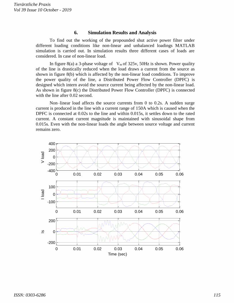
In figure 8(a) a 3-phase voltage of Vm of 325v, 50Hz is shown. Power quality
of the line is drastically reduced when the load draws a current from the source as
shown in figure 8(b) which is affected by the non-linear load conditions. To improve
the power quality of the line, a Distributed Power Flow Controller (DPFC) is
designed which intern avoid the source current being affected by the non-linear load.
As shown in figure 8(c) the Distributed Power Flow Controller (DPFC) is connected
with the line after 0.02 second.
Non–linear load affects the source currents from 0 to 0.2s. A sudden surge
current is produced in the line with a current range of 150A which is caused when the
DPFC is connected at 0.02s to the line and within 0.015s, it settles down to the rated
current. A constant current magnitude is maintained with sinusoidal shape from
0.015s. Even with the non-linear loads the angle between source voltage and current
remains zero.
0 0.01 0.02 0.03 0.04 0.05 0.06-400
-200
0
200
400
V load
0 0.01 0.02 0.03 0.04 0.05 0.06
-100
0
100
I lo
ad
0 0.01 0.02 0.03 0.04 0.05 0.06
-200
0
200
Time (sec)
Is
Tierärztliche Praxis
ISSN: 0303-6286
Vol 39 Issue 10 October - 2019
115
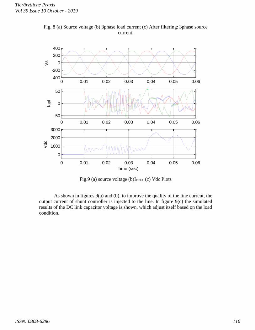
Fig. 8 (a) Source voltage (b) 3phase load current (c) After filtering: 3phase source
current.
0 0.01 0.02 0.03 0.04 0.05 0.06-400
-200
0
200
400V
s
0 0.01 0.02 0.03 0.04 0.05 0.06
-50
0
50
Iapf
0 0.01 0.02 0.03 0.04 0.05 0.06
0
1000
2000
3000
Time (sec)
Vdc
Fig.9 (a) source voltage (b)IDPFC (c) Vdc Plots
As shown in figures 9(a) and (b), to improve the quality of the line current, the
output current of shunt controller is injected to the line. In figure 9(c) the simulated
results of the DC link capacitor voltage is shown, which adjust itself based on the load
condition.
Tierärztliche Praxis
ISSN: 0303-6286
Vol 39 Issue 10 October - 2019
116
0 0.01 0.02 0.03 0.04 0.05 0.06
-50
0
50
Selected signal: 3.282 cycles. FFT window (in red): 2 cycles
Time (s)
0 5 10 15 200
2
4
6
8
10
12
14
Harmonic order
Fundamental (50Hz) = 57.58 , THD= 27.05%
Mag
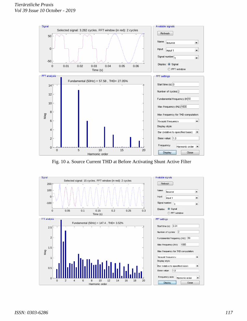
Fig. 10 a. Source Current THD at Before Activating Shunt Active Filter
0 0.05 0.1 0.15 0.2 0.25 0.3
-100
0
100
200
Selected signal: 15 cycles. FFT window (in red): 2 cycles
Time (s)
0 2 4 6 8 10 12 14 16 18 200
0.5
1
1.5
2
2.5
Harmonic order
Fundamental (50Hz) = 147.4 , THD= 3.52%
Mag
Tierärztliche Praxis
ISSN: 0303-6286
Vol 39 Issue 10 October - 2019
117
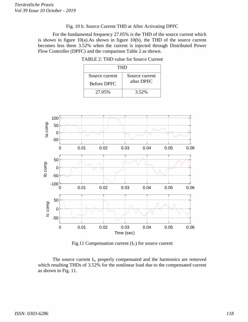
Fig. 10 b. Source Current THD at After Activating DPFC
For the fundamental frequency 27.05% is the THD of the source current which
is shown in figure 10(a).As shown in figure 10(b), the THD of the source current
becomes less them 3.52% when the current is injected through Distributed Power
Flow Controller (DPFC) and the comparison Table 2 as shown.
TABLE 2: THD value for Source Current
THD
Source current
Before DPFC
Source current
after DPFC
27.05% 3.52%
0 0.01 0.02 0.03 0.04 0.05 0.06
-50
0
50
100
Ia c
om
p
0 0.01 0.02 0.03 0.04 0.05 0.06-100
-50
0
50
Ib c
om
p
0 0.01 0.02 0.03 0.04 0.05 0.06
-50
0
50
Time (sec)
Ic c
om
p
Fig.11 Compensation current (IC) for source current
The source current Is, properly compensated and the harmonics are removed
which resulting THDs of 3.52% for the nonlinear load due to the compensated current
as shown in Fig. 11.
Tierärztliche Praxis
ISSN: 0303-6286
Vol 39 Issue 10 October - 2019
118

7. Conclusion
The significant objective of this Simulation are improving the power factor, to
balance the current from an unbalanced load condition and to reduce the harmonics
produced in the non-linear loads to compensate reactive power from the distributive
line. The working of the active filter satisfies to compensate the harmonics reactive
power, unbalanced load and also to improve power land these shown as the result of
the analysis .To fulfill the objectives the DPFC works perfectly which is shown by the
simulations that are simulated in MATLAB/SIMULINK. Using unity power factor
and less harmonics, Sinusoidal source current is produced. The harmonics and
reactive power of the system is compensated by the DPFC which has a controller
based on p-q theory.
References
[1] Singh, R., Singh, A. K., & Arya, R. K. (2012). Approximated fuzzy logic controlled shunt active
power filter for improved power quality. Expert Systems, 30(2), 152–161.
[2] Joydeep Sutradhar, U. Venkat A Reddy and Akhilesh A. Nimje, (2015) ‘Distributed Power Flow Controller for Power Quality Enhancement’, International Journal of Electrical, Electronics and Data Communication,
Special issue: 43-47.
[3] Prakash S and Hameed Hussain J, (2018) ‘Power Quality Improvement using FACTS Controllers using
DPFC’, International Journal of Pure and Applied Mathematics; 118(18): 301-309
[4] Yuan, Z., Haan, S. W. H. de, Ferreira, J. B., and Cvoric, D. (2010) A FACTS Device: Distributed Power-Flow
Controller (DPFC). IEEE Transactions on Power Electronics; 25(10): 2564–2572.
[5] Akhib Khan Bahamani, G.V. Siva Krishna Rao, A.A. Powly Thomas and Dr V.C. Veera Reddy, (2013)
‘Modelling and Digital Simulation of DPFCSystem using Matlab Simulink’, ‘International Journal of Emerging
Trends in Electrical and Electronics (IJETEE – ISSN: 2320-9569); 6(1).
[6] Shanker N., B. Sampath Kumar, (2010) Voltages sag and swell mitigation using DPFC for
Multibus system, International Journal of Engineering Research & Technology (IJERT), Vol. 2 issue
10.
[7] P. Ramesh, M. Damodara Reddy, 2012 ‘Modeling and Analysis of Distributed Power- Flow
Controller (DPFC)’, International Journal of Engineering Research and Applications; 2(2): 609-615.
[8] Y.-H. Song and A. Johns, (1999) ‘Flexible ac Transmission Systems (FACTS) (IEE Power and
Energy Series)’, vol. 30. London, U.K.: Institution of Electrical Engineers.
[9] N. G. Hingorani and L. Gyugyi, (2000) ‘Understanding FACTS : Concepts and Technology of
Flexible AC Transmission Systems’, New York: IEEE Press, 2000.
[10] L.Gyugyi, C.D. Schauder, S. L.Williams, T. R. Rietman,D. R. Torgerson, and A. Edris, (1995)
“The unified power flowcontroller:Anewapproach to power transmission control,” IEEE Trans. Power
Del.; 10(2) : 1085– 1097.
[11] Khazaie, J., Mokhtari, M., Badkubi, S., Khalilian, M., & Nazarpour, D. (2012) ‘ Sub-synchronous
resonance mitigation via distributed power flow controller’, International Transactions on Electrical
Energy Systems; 23(6) : 751–766
[12] Kumar, R., & Bansal, H. O. (2019) ‘Real-time implementation of adaptive PV-integrated SAPF to
enhance power quality’, International Transactions on Electrical Energy Systems: 1-22.
Tierärztliche Praxis
ISSN: 0303-6286
Vol 39 Issue 10 October - 2019
119

Prof.P.Rajarathinam is currently as a Principal at Adhiyamaan Polytechnic College,
Hosur, Tamilnadu, India. He has totally 16 years of experience in teaching (Till
September 2019) and 10 years of industrial experience. His research concentrated on the
behavior of power quality improvement using FACTS devices. His research interests
include Power quality, shunt/series active filter, and he has 16 years of experience in
teaching and research. He received post graduate degree M.E –Power electronics and
drives at Anna University, Chennai and He received his B.E Degree in EEE at Madurai Kamaraj
University, Madurai. He is persuing PhD in the area of power quality improvement.
Dr. G.Vijayakumar (ORCID Id: 0000-0003-1412-9879) is currently an Associate
Professor in the Department of Electrical Engineering at Muthayammal Engineering
college, Rasipuram, Tamilnadu, India. He has totally 13 years of experience in teaching
(Till May 2018). He received his doctorate in Electrical Engineering from Anna
University, Chennai, Tamilnadu, India in November 2014. He has been guiding 6 Ph.D.,
research scholar and has guided 04 post graduate projects and 11 undergraduate projects.
His research concentrated on the behaviour of Shunt active filter during harmonic compensation and
energy conservation. He has published over 19 articles in the peer-reviewed National & International
journals, and over 17 conference proceedings, and has delivered over 06 guest lecturers in the college
programmes. His h-index of 04 (Total citations 42, Source-Google Scholar) strongly endorses his
high research productivity. His research interests include Power quality, shunt/series active filter,
hybrid renewable energy sources, intelligent controllers. Currently, he is a reviewer for Journal of the
Institution of Engineers (India): series B- springer, Asian journal of control, journal of power
electronics and Journal of Circuits, Systems & Computers. He organized 05 Faculty Development
Programmes (Seminar/Workshop/Value added courses. He has acted as the chairperson on
international conference. He taught Electrical engineering students at under graduate and post graduate
level, over his experience, he produced 100 % results in many courses. He has the well known
professional experiences on board of studies, research and development activity, project coordination,
Exam coordination, Time table coordination, class advisor, NBA & NIRF activity and technical
training coordination to the students.
Tierärztliche Praxis
ISSN: 0303-6286
Vol 39 Issue 10 October - 2019
120