Embed Size (px)
Citation preview
An Innovative Method for the Seismic Retrofitting of Existing Steel
Moment Frame Structures Using Side Plate Technology
Behzad Rafezy1, Quang Huynh1, Henry Gallart1, Mohammad Kheirollahi2
1SidePlate Systems, Inc., Mission Viejo, CA92691. Email (corresponding author): [email protected] 2Sahand University of Technology, Tabriz, Iran
Abstract
The 1994 Northridge earthquake caused widespread damage to steel moment-resisting frames
including brittle fractures of beam-to-column welded moment connections. The damage was in the
form of brittle failures at the interface of the beam and column members and was detected in multi-
story buildings. Improvements to these pre-Northridge existing connections are often required as
part of an overall strengthening scheme, particularly when higher performance levels are desired.
To improve the behavior of moment resisting connections, the SidePlate connection was designed
and began to market as an alternative moment connection. The SidePlate connection technology
uses a pair of parallel full-depth side plates to connect the beam to the column, thereby eliminating
the traditional welded connection between the end of the beam and the face of the column flange.
While the SidePlate technology has been largely used in the construction of post-Northridge
buildings, its application in the retrofitting of existing buildings has been limited to date. In this
paper a new generation of SidePlate connections is proposed which is applicable for retrofitting
purposes and can improve the performance of existing steel structures. It is believed that the new
technology may lead to the best way for retrofitting existing building moment frame systems
instead of adding concrete shear walls and/or bracing elements. The proposed detail aims to
minimize the disturbances of existing building usage situation and at the same time improves the
performance of the system by increasing the rigidity of panel zone region and the stiffness of the
beam segment between the column face and plastic hinge location.
A case study including two multi-story steel moment frame structures was conducted to show that
the proposed technology can largely upgrade the performance level of existing structures.
Nonlinear analysis was performed to evaluate the vulnerability of the existing structures first, then
the proposed detail was implemented to the connections, and new performance levels were
obtained by means of nonlinear static analysis. The results showed that the plastic hinges are
always formed in beams instead of the columns. It has also been shown that the application of the
proposed details reduces the target displacement and improves the performance level of the
structures. It can be concluded that depending on the performance level of existing buildings, the
proposed detail might be considered as an efficient and optimized way of retrofitting those
structures.
Keywords: SidePlate connections, nonlinear static analysis, performance levels, retrofitting
1- Introduction
The seismic design philosophy of moment resistance frames is based on the flexible behavior
under earthquake forces and safe performance. Nevertheless, unexpected damages to steel
moment-resisting frame connections occurred in the 1994 Northridge earthquake. The majority of
damage occurred at the widely used welded unreinforced flange-bolted web (WUF-B)
“traditional” connection, known as the “pre-Northridge” moment connection. After the 1994
Northridge earthquake, researchers carried out various studies to find the reasons for the
unacceptable behavior of the connection. Investigations showed that the most common type of
damage in the majority of steel buildings was the premature brittle fractures of groove weld and
base metal due to the triaxial stress state in the connection.
After the damage evaluation in moment resistance frames, various practical solutions for each type
of damages were suggested. One of these proprietary designs was the SidePlate moment
connection system, invented by David L. Houghton. SidePlate steel frame connection technology
provides beam-to-column moment connections for use in steel special moment frame (SMF) and
steel intermediate moment frame (IMF) systems.
The SidePlate moment connection system is constructed of all welded fabrication, and features a
physical separation, or “gap,” between the face of the column flange and the end of the beam, by
means of parallel full-depth side plates which sandwich and connect the beam(s) and the column
together. Top and bottom beam flange cover plates are used, as necessary, to bridge any difference
between flange widths of the beam(s) and of the column. Vertical and horizontal shear plates, as
applicable, are provided at the beam and column webs, respectively.
Moment transfer from the beam to the side plates, and from the side plates to the column is
achieved through the fillet welds. The side plates are designed with adequate strength and stiffness
to force all significant plastic behavior of the connection system into the beam, in the form of
flange and web local buckling centered at a distance of approximately 1/3 the depth of the beam
away from the side plates (FEMA 350 [3]). SidePlate connection has no limit on the size of the
connection members or the type of column – it can be a wide flange shape or built up box column
or a cruciform column for biaxial applications (Davis [4]).
More than 20 full scale tests have been conducted on the SidePlate connection to prove that
SidePlate connection is a strong solution for the connection of beam and column in special moment
frame applications. Houghton [3] reported the result of experimental testing on three uniaxial test
specimens. These specimens consisted of a W36×150 beam, which was connected with full-depth
side plates to a W14×426 column. Also, another specimen that included of W36×170 beams was
tested. In this specimen, beams were connected to a built-up cruciform column, fabricated using
W36×230 sections in each principal direction, to form a three-sided connection. Study results were
generally qualitative and implied that the desired behavior, intended by the connection design
procedure, could be achieved easily.
While the SidePlate technology has been largely used in the construction of post-Northridge
buildings, its application in the retrofitting of existing buildings has been limited to date. In this
paper a new generation of SidePlate connections is proposed which is applicable for retrofitting
purposes and can improve the performance of existing steel structures. In this study, two steel
moment frame structures were selected to assess the vulnerability of the existing buildings. The
Basic Safety Objective (BSO) is used for the seismic assessment of the buildings. If the structure
under consideration does not achieve the required performance level, it has been retrofitted by

utilizing the SidePlate solution. The inelastic structural response has been expressed in terms of
plastic hinge status, story drifts derived by means of nonlinear static analyses.
2- SidePlate Connection Modeling
ETABS 2013 [6] was used for modeling and analyzing the structures. An illustration of the
numerical model established in ETABS to represent the connection is depicted in Fig. 1.
As illustrated in the figure, the lumped plasticity method is used for representing the nonlinear
behavior of beams utilizing plastic hinges whose location is determined according to experimental
observations. The rotational behavior of plastic hinges is modeled using a zero-length spring,
which connects two elastic beam segments to each other. Elastic beams are defined using actual
section properties measured from the test specimen [7]. As observed in experiment [7], the location
of the plastic hinge in a SidePlate connection is about one-third the beam height beyond the end
of the side plates (Fig. 2).
Effective use and correct implementation of the inherent SidePlate connection stiffness on the
global lateral frame of a structure is done as follows for ETABS 2013:
2-1- Method 1
The ETABS Built-in SidePlate Feature automatically creates a non-prismatic beam where each
fixed beam end represents the appropriate SidePlate connection stiffness properties from the
column face towards the beam centerline as follows:
Fig. 1. Assembled model in ETABS software
Fig.2. Location of plastic hinge in the SidePlate connection
Connection
𝒉
𝟑
Plastic
Hinge

• A section extends from column face to 77% of the nominal beam depth. The side plate section,
which consists of the physical side plates {A}, cover plates {B} and beam, has an approximate
moment of inertia (3) times that of the beam (Fig. 3). In this study, method 2 was used for modeling
of the structures.
Fig. 3. Full length beam to side plate detail
2-2- Method 2
Using Non-Prismatic Beam Sections
Another way of implementing SidePlate connection properties is to use non-prismatic beam
sections. This method can also be used for seismic or wind applications to help improve steel stress
ratios if the current design is at or above the allowable code values due to present limitations with
the built-in SidePlate feature.
3- Design and Analysis of Structures
3-1- Design of buildings
To investigate the performance of steel moment frames with SidePlate connections, a 2 and 6 story
moment frame are designed, with reference to pertinent provisions AISC 360-05 [8] and AISC
341-05 [9]. Design loads are computed for a standard office building. The buildings are assumed
to be located in Nashville, California. Figs. 4 and 5 show the two studied structures in this paper.
The first building consists of a 2 story shopping center which has 30 ft-long bays. The first and
second story height are 17.5 ft and 19.5 ft. Nominal yield strength equal to 50 ksi was used for
columns and girders. The second building is a 6-story residential building which has 32ft-long
bays. The existing lateral force resisting system consists of steel moment frames. The moment
frames are positioned at each of the two sides of the structure. The Site Class is D with very low
potential for liquefaction. The seismic parameters Ss and S1 per ASCE 7[10] are 1.85 and 0.84,
respectively. The value of 0.40g was assumed for the peak ground acceleration at the bedrock.

Fig. 4. Residential building Fig. 5. Shopping center
4- Nonlinear Static Analysis
Static pushover analysis is becoming a popular tool for seismic performance evaluation of existing
and new structures. The expectation is that the pushover analysis will provide adequate
information on seismic demands imposed by the design ground motion on the structural system
and its components. The pushover analysis of a structure is a static non-linear analysis under
permanent vertical loads and gradually increasing lateral loads. The equivalent static lateral loads
approximately represent earthquake induced forces. A plot of the total base shear versus top
displacement in a structure is obtained by this analysis that would indicate any premature failure
or weaknesses (Fig. 6). The analysis is carried out up to failure, thus it enables determination of
collapse load and ductility capacity. On one building frame, plastic rotation is monitored, and
lateral inelastic forces versus displacement response for the complete structure is analytically
computed. This type of analysis enables weaknesses in the structure to be identified. The decision
to retrofit can be taken in such studies.
Fig. 6. Capacity curve of structure
According to the ASCE14-13 [11], for linear and nonlinear procedures, the following actions
caused by gravity loads, QG, shall be considered for combination with actions caused by seismic
forces. Where the effects or actions of gravity loads and seismic forces are additive, the action
caused by gravity loads, QG , shall be obtained in accordance with Eq.(1):
QG =1.1(QD +QL +QS ) (1)
Where the effects or actions of gravity loads and seismic forces are counteracting, the action
caused by gravity loads, QG, shall be obtained in accordance with Eq.(2):
QG = 0.9QD (2)

Several lateral load patterns have been suggested. They are: (1) inverted triangle distribution
(modal pattern); (2) uniform distribution; (3) load distribution based on linear elastic dynamic
analysis or response spectrum analysis of the building; (4) the adaptive distribution, which is varied
as the inter story resistance changes in each load step; (5) distribution proportional to the product
of the mass and fundamental mode shape, which is used initially until the first yielding takes place.
Then the lateral forces are determined based on the product of the current floor displacement and
mass at each step; (6) a distribution based on mode shapes derived from secant stiffness at each
load step; The last three distributions are adaptive patterns, which try to establish equivalent lateral
load distribution based on a certain theoretical basis. However, their superiority over the simple
fixed load patterns has not been demonstrated. Due to the fact that the lateral force profiles in static
pushover analyses will influence the structural response, two different load patterns have been
utilized to represent the distribution of inertia forces imposed on the building. The first shape is
triangular according to the first mode of structure vibration and second load pattern is uniform load
pattern.
ASCE41-13 [11] document has developed the modeling procedures, acceptance criteria and
analysis procedures for pushover analysis. This document defines force-deformation criteria for
hinges used in pushover analysis. As shown in Fig. 7, five points labeled A, B, C, D, and E are
used to define the force-deflection behavior of the hinge and three points labeled IO, LS and CP
are used to define the acceptance criteria for the hinge. (IO, LS and CP stand for Immediate
Occupancy, Life Safety and Collapse Prevention respectively.) The values assigned to each of
these points vary depending on the type of member as well as many other parameters defined in
ASCE41-13[11] document.
Fig. 7. Force–deformation relationship of a typical plastic hinge
As stated before, two existing steel structures were selected for retrofitting using SidePlate
technology. Therefore, pushover analysis was done under two load patterns. In this study, the
performance criteria for immediate occupancy (IO), life safety (LS) and collapse prevention (CP)
were assigned to beams and columns according to ASCE 41-13. PMM hinges for columns and M3
hinges for beams were specified in this study. Plastic hinges are modeled at both ends of the beams
and columns. The objective is to retrofit the structures if the performance level didn't satisfy the
BSO level. The plastic hinges of SidePlate connections are located as shown in Fig. 8. Based upon
past and current testing of the SidePlate connection system, the centerline of hinge development
within the beam is located at approximately 1/3 of the beam depth (0.33*dbm) from the ends of the
side plates (Fig. 2). Similarly, the modeled hinge shall be placed at the same location. For this
study, the extension of the side plates is set by design as 77% of the nominal depth of the beam
(0.77*dbm) from the face of the column (rounded to nearest whole inch), and the center of hinge is
approximately 1/3 of the beam depth (0.33*dbm) from the end of the side plates; the hinge shall be
located at Lh from the centerline of column, where Lh = ½dcol + 1.1dbm, (0.77dbm + 0.33dbm =
1.1dbm).

5- Seismic Vulnerability Assessment of Structures
In this study, a seismic safety assessment was used for the evaluation of the existing buildings.
The considered structures were retrofitted using the SidePlate technology when they did not satisfy
BSO performance level. Nonlinear static analysis was conducted to evaluate the seismic
vulnerability of the chosen structures. The results of pushover analyses are presented below.
6- Results of Pushover Analyses
Pushover analysis of structures was performed in the X and Y directions as shown in Figs. 8 and
9. Two lateral load pattern were used in the analysis. 1) The first mode shape of the structures in
the X and Y directions; 2) uniform mode shape over the height. The monitored point of structures
are shown in Figs. 8 and 9.
6.1- Pushover Curves
The pushover curves obtained for the structures are plotted in Figs. 10 to 13 (maximum top
displacement at the center of mass (CM) versus the corresponding base shear).
0
500
1000
1500
2000
2500
3000
3500
4000
4500
0 2 4 6 8 10
Triangle load pattern
Uniform load pattern
Ba
se f
orce(k
ip)
Monitored Displacement (in)
0
1000
2000
3000
4000
5000
6000
0 2 4 6 8 10
Triangle load pattern
Uniform load pattern
Ba
se F
orce(k
ip)
Monitored Displacement (in)
Fig. 8. Monitored point for
Shopping center
Fig. 9. Monitored point for
Residential building
monitored point monitored point
Fig. 10. Pushover curves for shopping
center in the X direction
Fig. 11. Pushover curves for shopping
center in the Y direction

The plastic hinge distribution for the steel structures resulted from applying a lateral load to the
building with both lateral load patterns (uniform (ULP) and triangle (TLP)) and the gravity load
pattern of 0.9dead and 1.1(QD +QL +QS ) at the performance point are shown in Figs. 14 through
17. The results show that all the plastic hinges are in the phase of LS-CP and some of beams and
columns are in the phase of beyond E meaning performance level didn't satisfy the BSO objective;
therefore, structures need to be retrofitted.
0
1000
2000
3000
4000
5000
6000
7000
8000
9000
10000
0 5 10 15 20
Uniform load pattern
Triangle load pattern
Bas
eFo
rce
(kip
)
Monitored Displacement
(in)
0
1000
2000
3000
4000
5000
6000
7000
8000
9000
0 5 10 15 20 25
Uniform load pattern
Triangle load pattern
Bas
e F
orc
e(k
ip)
Monitored Displacement (in)
Fig. 12. Pushover curves for residential
building in the X direction
Fig. 13. Pushover curves for residential
building in the Y direction
Fig. 14. Plastic hinge distribution for
original shopping center under triangular
load pattern in Y direction
Fig. 15. Plastic hinge distribution for
original shopping center under uniform
load pattern in Y direction

7- Retrofitting of the Buildings
The nonlinear static analyses showed the buildings’ performance is in collapse prevention whereas,
the expected performance for this level of earthquake must be life safety. Due to this reason,
seismic retrofitting measure should be taken to increase the performance to target levels in terms
of global strength and stiffness. In order to enhance the buildings’ performances, SidePlate
connections have been used for retrofitting of steel the structures. This method adds significant
strength and stiffness to steel structures, in addition, this method leads to the best way for
retrofitting of existing buildings instead of adding concrete shear walls and/or bracing elements
and many conditions will be compatible with the original architectural plan of building.
7-1- Nonlinear Static Method (Pushover Analysis)
Nonlinear static analysis is used to understand the effect of the SidePlate connection in the
behavior of structures. Inelastic static analysis, or pushover analysis, has been the preferred method
for seismic performance evaluation due to its simplicity. The pushover analyses were performed
by applying monotonically increasing lateral loads such as triangular and uniform load pattern to
a structure. Nonlinear behavior of SidePlate connections defined using the experimental results
composed by SidePlate Systems, Inc. was used in adjusting the acceptance criteria and the five
points labeled A, B, C, D, and E define in the force–deformation behavior of the SidePlate
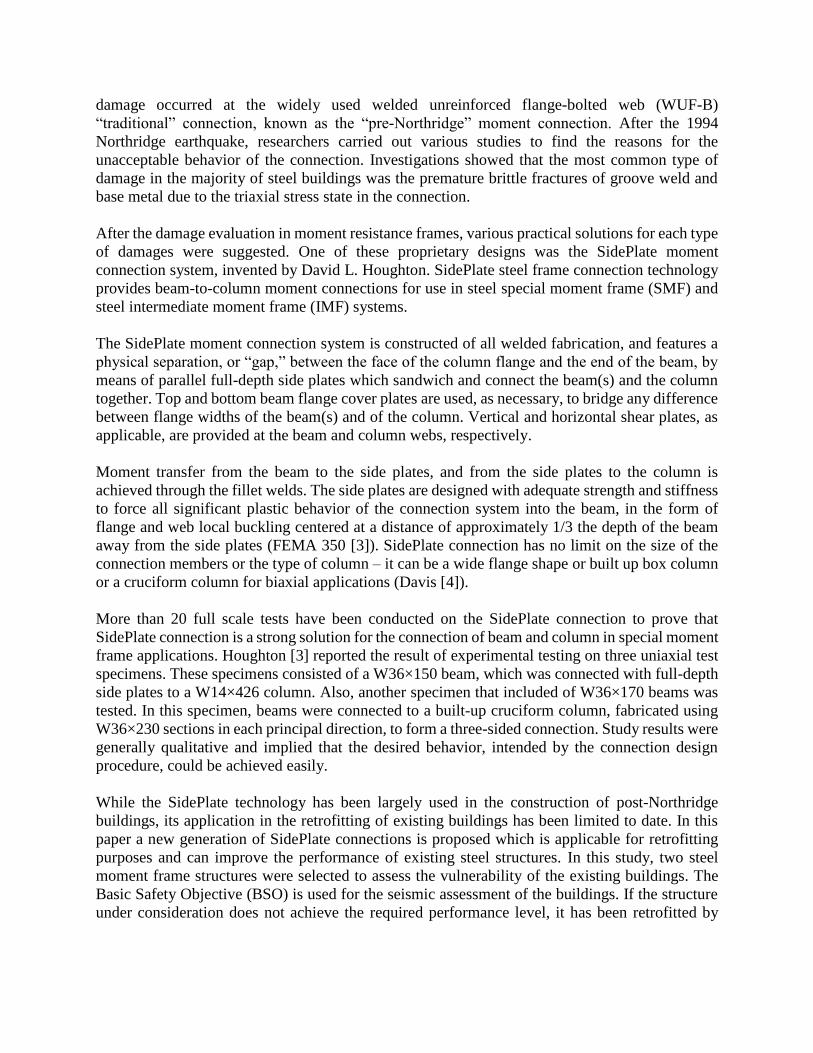
connection. The moment-rotation ratio and acceptance criteria of beams with SidePlate are shown
in Table 1 and Table 2. Also, a generalized force-displacement characteristics of hinge elements
for SidePlate is shown in Fig. 18. It needs to be noted that the acceptance criteria used in this study
need to be updated based on proposed retrofitting solution in real practical projects and the given
numbers are only useful for explaining the design philosophy.
Fig. 16. Plastic hinge distribution for
original residential building under
triangular load pattern in Y direction
Fig. 17. Plastic hinge distribution for
original residential building under uniform
load pattern in Y direction
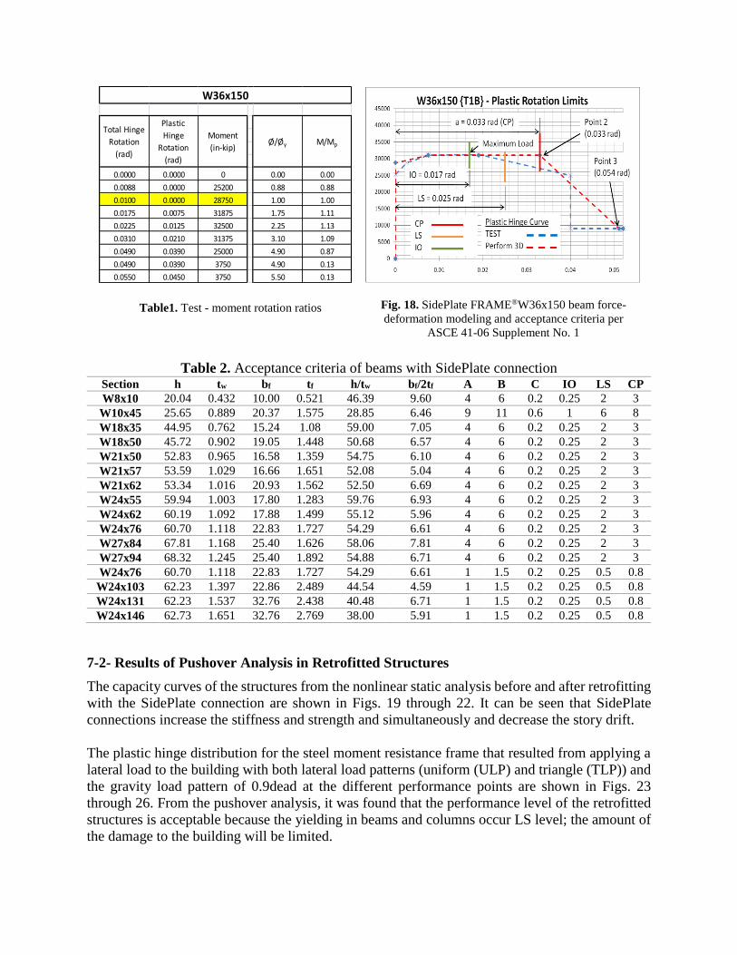
Table 2. Acceptance criteria of beams with SidePlate connection Section h tw bf tf h/tw bf/2tf A B C IO LS CP
W8x10 20.04 0.432 10.00 0.521 46.39 9.60 4 6 0.2 0.25 2 3
W10x45 25.65 0.889 20.37 1.575 28.85 6.46 9 11 0.6 1 6 8
W18x35 44.95 0.762 15.24 1.08 59.00 7.05 4 6 0.2 0.25 2 3
W18x50 45.72 0.902 19.05 1.448 50.68 6.57 4 6 0.2 0.25 2 3
W21x50 52.83 0.965 16.58 1.359 54.75 6.10 4 6 0.2 0.25 2 3
W21x57 53.59 1.029 16.66 1.651 52.08 5.04 4 6 0.2 0.25 2 3
W21x62 53.34 1.016 20.93 1.562 52.50 6.69 4 6 0.2 0.25 2 3
W24x55 59.94 1.003 17.80 1.283 59.76 6.93 4 6 0.2 0.25 2 3
W24x62 60.19 1.092 17.88 1.499 55.12 5.96 4 6 0.2 0.25 2 3
W24x76 60.70 1.118 22.83 1.727 54.29 6.61 4 6 0.2 0.25 2 3
W27x84 67.81 1.168 25.40 1.626 58.06 7.81 4 6 0.2 0.25 2 3
W27x94 68.32 1.245 25.40 1.892 54.88 6.71 4 6 0.2 0.25 2 3
W24x76 60.70 1.118 22.83 1.727 54.29 6.61 1 1.5 0.2 0.25 0.5 0.8
W24x103 62.23 1.397 22.86 2.489 44.54 4.59 1 1.5 0.2 0.25 0.5 0.8
W24x131 62.23 1.537 32.76 2.438 40.48 6.71 1 1.5 0.2 0.25 0.5 0.8
W24x146 62.73 1.651 32.76 2.769 38.00 5.91 1 1.5 0.2 0.25 0.5 0.8
7-2- Results of Pushover Analysis in Retrofitted Structures
The capacity curves of the structures from the nonlinear static analysis before and after retrofitting
with the SidePlate connection are shown in Figs. 19 through 22. It can be seen that SidePlate
connections increase the stiffness and strength and simultaneously and decrease the story drift.
The plastic hinge distribution for the steel moment resistance frame that resulted from applying a
lateral load to the building with both lateral load patterns (uniform (ULP) and triangle (TLP)) and
the gravity load pattern of 0.9dead at the different performance points are shown in Figs. 23
through 26. From the pushover analysis, it was found that the performance level of the retrofitted
structures is acceptable because the yielding in beams and columns occur LS level; the amount of
the damage to the building will be limited.
0.0000 0.0000 0 0.00 0.00
0.0088 0.0000 25200 0.88 0.88
0.0100 0.0000 28750 1.00 1.00
0.0175 0.0075 31875 1.75 1.11
0.0225 0.0125 32500 2.25 1.13
0.0310 0.0210 31375 3.10 1.09
0.0490 0.0390 25000 4.90 0.87
0.0490 0.0390 3750 4.90 0.13
0.0550 0.0450 3750 5.50 0.13
W36x150
Total Hinge
Rotation
(rad)
Plastic
Hinge
Rotation
(rad)
Moment
(in-kip)Ø/Øy M/Mp
Fig. 18. SidePlate FRAME®W36x150 beam force-
deformation modeling and acceptance criteria per
ASCE 41-06 Supplement No. 1
Table1. Test - moment rotation ratios

0
1000
2000
3000
4000
5000
6000
0 2 4 6 8 10
without Side Plate
With Side Plate
Ba
se f
orce(k
ip)
Monitored Displacement(in)
0
1000
2000
3000
4000
5000
6000
0 2 4 6 8 10
Without Side Plate
With Side Plate
Ba
se F
orce(k
ip)
Monitored Displacement(in)
0
1000
2000
3000
4000
5000
6000
7000
8000
9000
10000
0 5 10 15 20
with side plate
without side plate
Ba
seF
orce(k
ip)
Monitored Fisplacement(in)
0
1000
2000
3000
4000
5000
6000
7000
8000
0 5 10 15 20 25
without side plate
with side plateBa
se F
orce(k
ip)
Monitored Displacement(in)
Fig. 19. Comparison of capacity curves for
original and retrofitted shopping center in X
direction under triangular load pattern
Fig. 20. Comparison of capacity curves for
original and retrofitted shopping center in Y
direction under triangular load pattern
Fig. 21. Comparison of capacity curves for
original and retrofitted residential building in X
direction under triangular load pattern
Fig. 22. Comparison of capacity curves for
original and retrofitted residential building in Y
direction under triangular load pattern
Fig. 23. Plastic hinge distribution for
retrofitted shopping center under
triangular load pattern in X direction
Fig. 24. Plastic hinge distribution for
retrofitted shopping center under uniform
load pattern in X direction

8- Finite Element Analysis
Nonlinear finite element analysis (FEA) with 3-dimensional solid brick elements was used to
analyze the SidePlate retrofitted connection region. Fig. 27 shows a model of an interior moment
connection where the beam-to-column assembly were cut at the points of inflection which occurs
at column mid height and beam mid spans. The column is then loaded cyclically at cycles at 4%
story drift at the top.
Fig. 28 and Fig. 29 show the details of the connection. From the details, the process of reinforcing
an existing WUF-B connection, which includes field welding and bolting, can be done with
minimal damage to the building. The concrete slab above can be left intact since all the welding
will be under the slab. The SidePlate retrofit solution presents an economical solution to
reinforcing existing structures and meeting modern building code requirement for a safe structure.
Fig. 27. Side elevation
Fig. 25. Plastic hinge distribution for
retrofitted residential building under
triangular load pattern in the X direction
Fig. 26. Plastic hinge distribution for
retrofitted residential building under
uniform load pattern in the X direction

Fig. 28. 3-D isometric view Fig. 29. Front elevation
Fig. 30 shows the average triaxial stress distribution in the connection as the column is loaded
laterally at 4% drift. Triaxial stress is a well-known parameter that causes early fracture. Many
of the pre-Northridge moment frame connections suffered from this phenomenon. When
comparing a WUF-B connection to a SidePlate retrofitted solution, it can be shown that triaxial
stress in the connection is significantly reduced, which will significantly reduce the change of early
fracture. Fig. 31 shows that plasticity as a form of energy dissipation is pushed into the beam. The
plastic hinge formation occurred in the beam, which aligns with modern structural design
principles. In addition to significantly lowering the chance of early fracture, Fig. 32 also shows
that with the SidePlate retrofit solution, the connection is stiffer and will dissipate more energy as
the structure goes under high seismic loading, which is likely to give the connection the required
stiffness to meet modern building code requirements.
a) WUF-B b) SidePlate Retrofit Solution
Fig. 30. Average triaxial stress contour plot at 4% drift (𝜎 = −50 𝑘𝑠𝑖)
Fig. 31. Beam plastic hinge formation (von Mises Stress, 𝜎𝑦 = 50 𝑘𝑠𝑖)
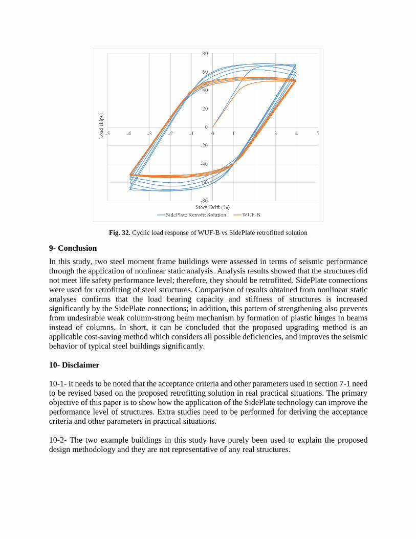
Fig. 32. Cyclic load response of WUF-B vs SidePlate retrofitted solution
9- Conclusion
In this study, two steel moment frame buildings were assessed in terms of seismic performance
through the application of nonlinear static analysis. Analysis results showed that the structures did
not meet life safety performance level; therefore, they should be retrofitted. SidePlate connections
were used for retrofitting of steel structures. Comparison of results obtained from nonlinear static
analyses confirms that the load bearing capacity and stiffness of structures is increased
significantly by the SidePlate connections; in addition, this pattern of strengthening also prevents
from undesirable weak column-strong beam mechanism by formation of plastic hinges in beams
instead of columns. In short, it can be concluded that the proposed upgrading method is an
applicable cost-saving method which considers all possible deficiencies, and improves the seismic
behavior of typical steel buildings significantly.
10- Disclaimer
10-1- It needs to be noted that the acceptance criteria and other parameters used in section 7-1 need
to be revised based on the proposed retrofitting solution in real practical situations. The primary
objective of this paper is to show how the application of the SidePlate technology can improve the
performance level of structures. Extra studies need to be performed for deriving the acceptance
criteria and other parameters in practical situations.
10-2- The two example buildings in this study have purely been used to explain the proposed
design methodology and they are not representative of any real structures.
References
1- Engelhardt, M.D., Sabol, T.A., Aboutaha, R.S., Frank, K.H.,(1995). ‘‘Overview of the AISC
Northridge Moment Connection Test Program, ’’. National Steel World Conference, Texas.
2- Houghton, D.L.,(1998), ‘‘The Side plate Moment Connection: A Design Breakthrough
Eliminating Recognized Vulnerabilities in Steel Moment Frame Connections’’. "Proceedings of
the 2nd World Conference on Steel Construction, San Sebastian, Spain.
3- Federal Emergency Management Agency, FEMA-350: Recommended Seismic Design Criteria
for New Welded Steel Moment Frame Buildings, Sacramento, California, 2000.
4- Davis, J.(2001). “Steel Moment-frame Buildings. Part 2’’.Structural Engineer. June 2001.
5- Federal Emergency Management Agency, FEMA 267: “ Interim Guidelines: Evaluation,
Repair, Modification and Design of Steel Moment Frames’’, Report No. SAC-95-02.
6- CSI, ETABS2013 V-13.1.1, Integrated finite element analysis and design of structures basic
analysis reference manual, Berkeley, California (USA); Computers and Structures Inc.
7- Side Plate FRAME® SMF Connection, Design Criteria, Nonlinear Hinge Curves Developed
from Full-Scale Testing,(2011), Side Plate Systems, Inc.
8- AISC, American Institute of Steel Construction, ‘‘Specifications for structural steel buildings’’,
AISC 360-05, Chicago, Illinois, March (2005).
9- AISC, American Institute of Steel Construction, ‘‘Seismic provisions for structural steel
buildings’’, AISC 341-05, Chicago, Illinois (March 2005).
10- ASCE/SEI 7-10, (2010).‘‘Minimum Design Loads for Buildings and Other Structures’’,
American Society of Civil Engineers, Reston, Virginia.
11- ASCE/SEI 41-13,(2013). ‘‘Seismic Evaluation and Retrofit of Existing Buildings’’, American
Society of Civil Engineers, Reston, Virginia.