Embed Size (px)
Citation preview

“Proceedings of the 2004 American Society for Engineering Education Annual Conference & Exposition
Copyright © 2004, American Society for Engineering Education”
Session 2432
An Innovative Electronics Laboratory System for On Campus and Distance
Learning Applications
Carlo Sapijaszko, Genevieve I. Sapijaszko
Thomson Delmar Learning, DeVry University
Abstract
The eTCB, a custom-built trainer board that works in concert with National Instruments’ NI ELVIS1 (Electronics Laboratory Virtual Instrumentation Suite) and a personal computer, is a solution for students who need to perform laboratory experiments, whether at a distance or on campus. This solution offers students the convenience of purchasing a laboratory manual and a custom-built eTCB (electronics training circuit board), which are designed to offer a complete set of laboratory experiments in DC and AC circuit analysis and design courses. The lab manual and eTCB form a complete package that does not require students to add extra components. The eTCB was designed in such a way as to replace the functionality of a traditional breadboard, with the concept of a configurable circuit. Well-chosen configurable circuit blocks have been embedded in the eTCB, and the connections between the various circuit blocks are made with relays driven by software. With NI ELVIS seamlessly integrated into this solution, students have access to an array of instruments, including a DMM, an Oscilloscope, a Function Generator, a Variable Power Supply, a Dynamic Signal Analyzer, and more. This solution ensures that students can perform laboratory experiments with real components, manually measure real electrical quantities, and work with industry-standard designs. Students perform experiments in a self-guided environment. In this environment, students receive immediate, critically important feedback regarding their work. Since this solution is software-centric, once a student performs a measurement a computer compares it with conditions defined by the author of the experiment. At this point a guiding message is rendered back to the student. This message offers students the information regarding the accuracy of the measurement and, if necessary, suggestions for corrective actions to obtain an accurate measurement. Monitoring computers can remotely observe the experiment activities that students are engaged in via the Internet. The combination of relatively low cost for the complete laboratory solution, an innovative self-guided approach for students to perform experiments, and the ability to remotely monitor student activity makes this an ideal solution for both on-campus and distance learning. Additional eTCB modules are being developed in an effort to build a complete set of laboratory experiments for the undergraduate curriculum. Those modules will include laboratory content for electronic devices, digital electronics, electronic communications, electronic control systems, and more.

“Proceedings of the 2004 American Society for Engineering Education Annual Conference & Exposition
Copyright © 2004, American Society for Engineering Education”
1. Introduction
With the advance of education into the on-line environment there was a need to support the delivery of laboratory content on-line and with little supervision. Math courses, English courses, and even computer courses are easily transferred from on-campus teaching to on-line teaching. Electronics lectures can easily be transferred as well; however, there has always been a challenge with transferring the laboratory experiments without making all of the experiments simulation based. Educators have always felt that students need to be physically engaged while performing electronics experiments, and that students should perform the experiments using industry compatible equipment. How can students perform a meaningful experiment with little supervision from an educator while building their experiment circuits? If students are using the traditional breadboard approach to building their experiment circuits, how is it possible to verify that the students have built their circuits correctly? How is it possible to effectively provide assistance when students are working with such an open platform? With the controlled environment, the self-guiding approach, and the remote monitoring capabilities that the eTCB system provides, the challenge of providing a laboratory experience to students in an on-line learning environment can be addressed.
2. Overview of the eTCB System
The hardware of the eTCB system consists of a PC, a data acquisition device (DAQ), a DAQ cable, the NI ELVIS workstation, and the eTCB board with its accompanying Lab Manual. This system is self-contained; no other electrical components or hardware is required. The function of the PC in the eTCB system is to provide a graphical user interface for all of the instruments programmed into the eTCB software application. The purpose of the eTCB board is to provide a platform on which students can perform laboratory experiments. The eTCB board contains configurable circuits, which are appropriate for a given curriculum. Its purpose is also to communicate circuit configuration with the PC. The eTCB lab manual offers an exhaustive array of laboratory experiments for a given curriculum. The fact that this system is self-contained helped educators and students who evaluated this system to be able to focus on achieving experiments objectives more effectively. This was primarily due to the fact that far less distractions were caused by tasks associated with manual assembly of circuits on traditional breadboards. Educators have also indicated that those tasks are becoming less and less relevant in today’s PCB saturated industry.

“Proceedings of the 2004 American Society for Engineering Education Annual Conference & Exposition
Copyright © 2004, American Society for Engineering Education”
Figure 1 1. PC, 2.DAQ Device, 3. DAQ Cable, 4. eTCB Board, 5. NI ELVIS Workstation, 6. eTCB Lab Manual
Figure 2
eTCB board interfaced with NI ELVIS workstation

“Proceedings of the 2004 American Society for Engineering Education Annual Conference & Exposition
Copyright © 2004, American Society for Engineering Education”
3. Replacing Breadboards with Configurable Circuits
The eTCB board has been designed with a concept of configurable circuits as means of building experiment circuits. This approach eliminates the need for breadboards as a means of constructing electrical circuits. This alleviates the difficulties of debugging student-constructed circuits in an environment where direct supervision by an instructor is not available. Circuits to be examined during a given laboratory experiment are configured into the eTCB board with the use of a PC. Once the configuration is loaded into the eTCB board buffer, appropriate relays are turned ON and their contacts make connections between various circuit blocks, thus configuring the circuits. A schematic diagram of the DC module is shown in Figure 3. It illustrates the available DC circuit blocks from which specific circuits can be configured.
Figure 3
Circuit building blocks for the DC module
By turning ON the circled relays in Figure 3, the circuit in Figure 4 is configured. In this manner, circuits of varying complexity can be configured by selecting appropriate relays to turn ON or OFF.
Figure 4
Configured DC circuits

“Proceedings of the 2004 American Society for Engineering Education Annual Conference & Exposition
Copyright © 2004, American Society for Engineering Education”
As part of every experiment procedure, students are asked to configure an appropriate experiment circuit. Although Figure 3 shows DC voltage sources and resistive loads only, other modules address the need for AC voltage sources, and passive components such as capacitors and inductors. Figure 5 shows configurable circuits addressing the need for an AC voltage source and other passive components.
Figure 5
Circuit building blocks for the AC module
By turning ON the circled relays in Figure 5, the circuit in Figure 6 is configured. In this manner, circuits of varying complexity can be configured by selecting appropriate relays to turn ON or OFF.
Figure 6
Configured AC circuits
Early versions of this system were criticized, because it did not provide for different component ratings. To address this concern, expressed by educators, the current version allows for flexibility in choosing component ratings. In order to add further flexibility to the multitude of circuits that can be configured, most of the components come as pairs. Components in pairs differ from each

“Proceedings of the 2004 American Society for Engineering Education Annual Conference & Exposition
Copyright © 2004, American Society for Engineering Education”
other by their ratings. As an example, a resistor pair is made up of 470 Y resistor and a 820 Y resistor. Components are selected by using a physical jumper, which engages one of the two components in a pair. Another possibility is to place two jumpers, engaging both components at the same time. Figure 7 illustrates the concept of jumper-selectable components.
Figure 7
Jumper-selectable components
All circuit configurations are performed with the eTCB Configuration instrument available from the eTCB Launch panel. Clicking on the icon representing a relay contact turns ON a physical relay located on the eTCB board. This action also highlights the portion of the circuit that has just been connected to the circuit.
Figure 8
Configuring a DC circuit using eTCB Configuration Instrument
“Proceedings of the 2004 American Society for Engineering Education Annual Conference & Exposition
Copyright © 2004, American Society for Engineering Education”
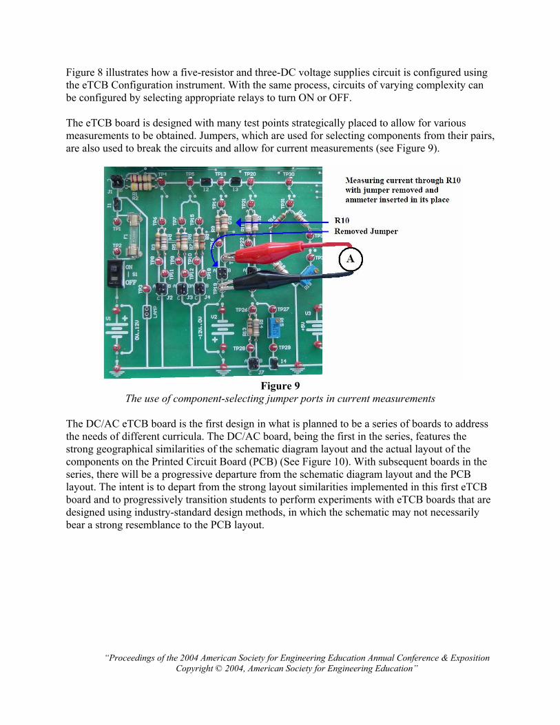
Figure 8 illustrates how a five-resistor and three-DC voltage supplies circuit is configured using the eTCB Configuration instrument. With the same process, circuits of varying complexity can be configured by selecting appropriate relays to turn ON or OFF. The eTCB board is designed with many test points strategically placed to allow for various measurements to be obtained. Jumpers, which are used for selecting components from their pairs, are also used to break the circuits and allow for current measurements (see Figure 9).
Figure 9
The use of component-selecting jumper ports in current measurements
The DC/AC eTCB board is the first design in what is planned to be a series of boards to address the needs of different curricula. The DC/AC board, being the first in the series, features the strong geographical similarities of the schematic diagram layout and the actual layout of the components on the Printed Circuit Board (PCB) (See Figure 10). With subsequent boards in the series, there will be a progressive departure from the schematic diagram layout and the PCB layout. The intent is to depart from the strong layout similarities implemented in this first eTCB board and to progressively transition students to perform experiments with eTCB boards that are designed using industry-standard design methods, in which the schematic may not necessarily bear a strong resemblance to the PCB layout.

“Proceedings of the 2004 American Society for Engineering Education Annual Conference & Exposition
Copyright © 2004, American Society for Engineering Education”
Figure 10
Strong similarities of the geographical layout of the PCB and the schematic diagram.
4. Integration of NI ELVIS into the eTCB system:
The eTCB software application was developed by adding additional functions to an existing software application designed by National Instruments specifically for NI ELVIS. Functions that transform the existing NI software into the eTCB software allow the user to capture measurements and instrument settings, to communicate with the eTCB board, to perform a self-diagnostic, to access measurements and instrument settings remotely, to open an eTCB experiment file, and to display self-guiding messages. The key feature of the eTCB software application is its ability to capture and interpret the measurement values and instrument settings. Because of the software-centric design of the eTCB system, all measurement values and instrument settings are available for further analysis within a PC. The eTCB system takes advantage of this fact and adopts a model where the student is asked to capture experiment data for every step of an experiment. The purpose of this action is to trigger the PC to interpret the captured set of instrument data. This data is a collection of measured values and instrument settings. This data is then compared to the data specified by the author of the experiment. At this point, the eTCB software renders a message to the user informing the student of whether a particular instrument setting is correct to perform a given measurement and whether the measured value is within an acceptable range. The purpose of the self-diagnostic feature built into the eTCB system is to assure the student that the eTCB system is performing within specified tolerances. This information is critically important to students, who may otherwise divert their focus from performing the experiment to unnecessarily questioning the platform on which they perform the experiment. The eTCB software application also allows for remote monitoring of student measurements and instrument settings. This is done with DataSocket2,3 technology developed by National
“Proceedings of the 2004 American Society for Engineering Education Annual Conference & Exposition
Copyright © 2004, American Society for Engineering Education”
Instruments. A remote monitoring PC needs to have eTCB-Monitor software installed in order to observe the activities performed on the eTCB system PC.
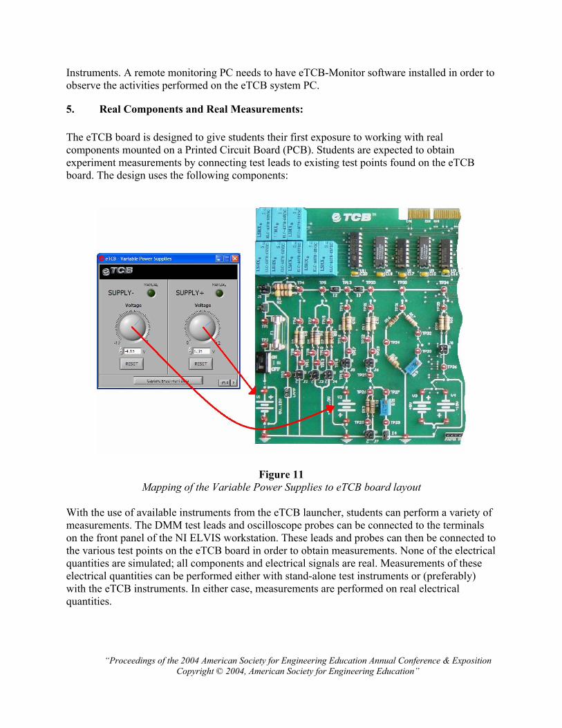
5. Real Components and Real Measurements:
The eTCB board is designed to give students their first exposure to working with real components mounted on a Printed Circuit Board (PCB). Students are expected to obtain experiment measurements by connecting test leads to existing test points found on the eTCB board. The design uses the following components:
Figure 11
Mapping of the Variable Power Supplies to eTCB board layout
With the use of available instruments from the eTCB launcher, students can perform a variety of measurements. The DMM test leads and oscilloscope probes can be connected to the terminals on the front panel of the NI ELVIS workstation. These leads and probes can then be connected to the various test points on the eTCB board in order to obtain measurements. None of the electrical quantities are simulated; all components and electrical signals are real. Measurements of these electrical quantities can be performed either with stand-alone test instruments or (preferably) with the eTCB instruments. In either case, measurements are performed on real electrical quantities.

“Proceedings of the 2004 American Society for Engineering Education Annual Conference & Exposition
Copyright © 2004, American Society for Engineering Education”
Figure 12
Similarities between a virtual eTCB instrument and a physical stand-alone instrument
Figure 12 illustrates how DMM test leads connected to the front panel of an NI ELVIS workstation that has been set to operate as an eTCB DMM, serve the same function as a stand-alone physical DMM.
6. Self-Guided Environment
The eTCB system was developed to aid in the delivery of laboratory curriculum. In an effort to accomplish this goal, the eTCB system is equipped with a software feature that allows students to perform laboratory experiments with little or no direct supervision from instructors. For each step of the experiment procedure, the author defines the type of measurement that needs to be obtained, the acceptable instrument settings, and the acceptable range for the measured quantity. In addition to defining those parameters, self-guiding messages have been created to guide the students as they perform the experiment. The display of the guiding messages is triggered by the captured instrument settings and measured values as the experiment is performed.
Experiment Author perspective:
Let us consider an example of a step in an experiment procedure where the student is asked to perform a voltage measurement across a DC voltage supply. The following is a section of the lab manual developed for the eTCB system:

“Proceedings of the 2004 American Society for Engineering Education Annual Conference & Exposition
Copyright © 2004, American Society for Engineering Education”
Step #1 Using the eTCB Configuration VI (DC Module), configure the circuit in Figure ab-c (Capture
configuration data to verify its accuracy).
Figure ab-c
Step #2 Using the Variable Power Supplies VI, set voltage source V1 to 7.0 V (Capture this data to verify
its accuracy). Keep in mind that this setting is just a good indication of what the voltage of V1 is
set to. Variable Power Supplies often need to be adjusted (tuned) in order to set their output
voltage precisely. Keep the Variable Power Supplies VI open; if you close it, all the variable
voltage supplies will reset to 0 V.
Step #3 Using the Digital Multimeter (DMM)VI, measure the Supply Voltage V1 with respect to ground.
Adjust the output of the Variable Power Supplies if necessary (Capture this data to verify its
accuracy).
Let us focus on step #3 in the above experiment procedure. In order for the user to perform this procedure correctly, the DMM function selection must be set on “DC Voltage”, and the range needs to be set on “10 V” or “Auto”; it is best if the “RUN” function is selected as well. The acceptable measurement of DC voltage of a correctly adjusted Variable Power Supply is 7.0 V, ±0.1 V. The author of this experiment needs to specify all of the above conditions and, when appropriate, author a self-guiding message to guide the student to a successful completion of this particular step in the experiment. The author can use the eTCB-Creator software application, which was developed to aid authors both in changing existing experiment files and in developing new ones.

“Proceedings of the 2004 American Society for Engineering Education Annual Conference & Exposition
Copyright © 2004, American Society for Engineering Education”
Figure 13
DMM authoring tools where instrument settings are specified and messages authored.
Figure 13 illustrates the eTCB-Creator software application that allows the author of this experiment to specify the acceptable instrument settings. As stated before, the DMM function needs to be set to measure “DC Voltage”; therefore, the “DC Voltage” function is chosen as the “Ideal” selection. In anticipation that some students will select the “AC Voltage” function to perform this measurement, the author has chosen the “AC Voltage” function for “Option 1”. The available message when students select this function will be as follows:
This Function setting is incorrect; it measures AC voltage. Please measure the DC voltage with the DC function.
DC function selected:
--
Please try again.
If students should happen to select any other function, the available message will be as follows:
This Function setting is incorrect. This step requires you to measure a DC voltage. Carefully read your lab
instructions and choose a different Function setting.
--
Please try again.
If the student continues to select the wrong function setting, the message available will be more direct and descriptive as shown below.

“Proceedings of the 2004 American Society for Engineering Education Annual Conference & Exposition
Copyright © 2004, American Society for Engineering Education”
Please measure the DC voltage with the DC function.
DC function selected:
--
Please try again.
Other conditions and self-guiding messages for the DMM and other instruments are specified and authored in a similar manner. The authors of the experiments also have the ability to specify messages based on different measurement values that student will obtain. Figure 14 illustrates the process of specifying measurement values and creating messages based on those values.
Figure 14
DMM authoring tools where measurement values are specified and messages are created.
There are four ranges for which different messages can be specified. The first two ranges are inclusive, where the two defining values specify the minimum and the maximum value in the range. The other two ranges are defined by two values that specify where the range ends and where it begins again. Figure 15 illustrates this concept.

“Proceedings of the 2004 American Society for Engineering Education Annual Conference & Exposition
Copyright © 2004, American Society for Engineering Education”
Figure 15
An example of measurement range setting
Step #3 in this experiment is asking the student to measure the voltage across a Variable Power Supply and, if necessary, to adjust it to obtain an output voltage of 7.0 V. The following message will be available to the students when they obtain the reading of 7.0 V (±0.1 V) (Range 1). Congratulations: This voltage reading is within the acceptable range. Do not spend any more time trying to obtain
another measurement.
--
Please proceed further.
In anticipation of students reversing the DMM leads, a different guiding message is available. When students obtain a measurement within the acceptable range, but with a negative polarity (Range 2), the message available will be as follows: This voltage reading has wrong polarity. Most likely your DMM probes are reversed. Ensure your DMM probe
“Voltage HI” is placed at TP1, and DMM probe “Voltage LO” is placed at the GND node.
--
Please try again.
In anticipation of the Variable Power Supply’s initial output voltage not being within the acceptable range, self-guiding messages will be available for students when they obtain measurements that are either below 6.9 V or above 7.1 V. When a measurement below 6.9 V is obtained, the following message is available for students.

“Proceedings of the 2004 American Society for Engineering Education Annual Conference & Exposition
Copyright © 2004, American Society for Engineering Education”
This voltage reading is incorrect; it is below the acceptable range. Possible reasons for this reading are:
You are not measuring this value at the correct place on the eTCB.
Ensure your DMM probe “Voltage HI” is placed at TP1, and DMM probe “Voltage LO” is placed at the GND
node.
Output of the Variable Power Supply needs to be readjusted:
Power supplies often need to be adjusted to obtain an accurate output voltage. Continue to perform this
measurement while adjusting the Variable Power Supply to obtain a better reading.
--
Please take corrective actions
When a measurement above 7.1 V is obtained, the following message will be available for students. This voltage reading is incorrect; it is above the acceptable range. Possible reasons for this reading are:
You are not measuring this value at the correct place on the eTCB.
Ensure your DMM probe “Voltage HI” is placed at TP1, and DMM probe “Voltage LO” is placed at the GND
node.
Output of the Variable Power Supply needs to be readjusted:
Power supplies often need to be adjusted to obtain an accurate output voltage. Continue to perform this
measurement while adjusting the Variable Power Supply to obtain a better reading.
--
Please take corrective actions.

“Proceedings of the 2004 American Society for Engineering Education Annual Conference & Exposition
Copyright © 2004, American Society for Engineering Education”
Messages for use with the eTCB system can be authored using any editor capable of saving documents as HTML files. The collection of all messages for a given experiment is then compiled into a Help file.
Student perspective:
A student needs to use the DMM while performing step # 3 of the experiment. The settings on the DMM are chosen by the student, the DMM probes are attached to the test point, and the measurement is obtained. At that point a student will “Capture Experiment Data” by clicking on the button available on the bottom of all eTCB instruments. When that action is performed, a pull-down window appears to offer the student a place to enter the step that is currently being performed. Once the student selects the step that is being performed, a list of self-guiding messages is offered.
Figure 16
A sequence of events performed by a student
Figure 16 illustrates the sequence of actions performed by a student verifying the correctness of the instrument settings and the accuracy of the measured voltage. In this scenario, a student has selected an incorrect Function and an incorrect Range for this measurement. There are two messages available for the student. When the student double clicks on the first title, the following message is displayed:
This Function setting is incorrect; it measures AC voltage. Please measure the DC voltage with
the DC function.
DC function selected:

“Proceedings of the 2004 American Society for Engineering Education Annual Conference & Exposition
Copyright © 2004, American Society for Engineering Education”
--
Please try again.
When the user double clicks on the second title, the following message is displayed:
This range setting is incorrect. Carefully consider choosing the range setting to maximize the
measurement accuracy. Think of an optical zoom function on your camera. If you want to take a
detailed (accurate) photograph of an object, you sometimes need to zoom in or zoom out in order
to fill in the viewable area on your camera with the image of the object you want to photograph.
This situation is similar, in that you want to choose your range setting so that an expected signal
will fill in (use up) most of the range of the DMM.
Also, keep in mind that you have an auto range function available on this DMM.
Auto range function selected:
--
Please try again.
With a properly authored experiment, students can utilize the self-guiding messages to successfully and meaningfully complete a given experiment.
“Proceedings of the 2004 American Society for Engineering Education Annual Conference & Exposition
Copyright © 2004, American Society for Engineering Education”
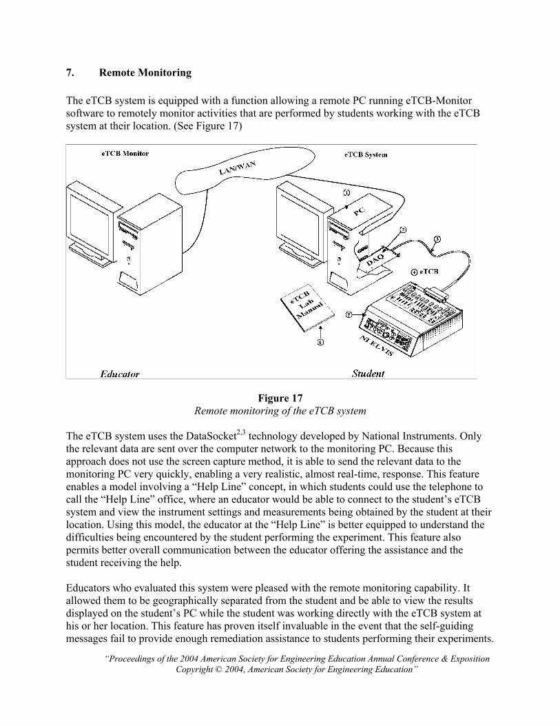
7. Remote Monitoring
The eTCB system is equipped with a function allowing a remote PC running eTCB-Monitor software to remotely monitor activities that are performed by students working with the eTCB system at their location. (See Figure 17)
Figure 17
Remote monitoring of the eTCB system
The eTCB system uses the DataSocket2,3 technology developed by National Instruments. Only the relevant data are sent over the computer network to the monitoring PC. Because this approach does not use the screen capture method, it is able to send the relevant data to the monitoring PC very quickly, enabling a very realistic, almost real-time, response. This feature enables a model involving a “Help Line” concept, in which students could use the telephone to call the “Help Line” office, where an educator would be able to connect to the student’s eTCB system and view the instrument settings and measurements being obtained by the student at their location. Using this model, the educator at the “Help Line” is better equipped to understand the difficulties being encountered by the student performing the experiment. This feature also permits better overall communication between the educator offering the assistance and the student receiving the help. Educators who evaluated this system were pleased with the remote monitoring capability. It allowed them to be geographically separated from the student and be able to view the results displayed on the student’s PC while the student was working directly with the eTCB system at his or her location. This feature has proven itself invaluable in the event that the self-guiding messages fail to provide enough remediation assistance to students performing their experiments.

“Proceedings of the 2004 American Society for Engineering Education Annual Conference & Exposition
Copyright © 2004, American Society for Engineering Education”
8. Lab Manual
The Lab Manual includes over 30 DC/AC experiments using the eTCB system and fulfills the requirements of any DC/AC course by taking the student from the basics of engineering notation all the way to passive filter analysis and design. Each lab features:
• Problem Statement – presents a practical application. • Concept – reviews the theoretical background of the experiment’s content. • Learning Objectives – outlines a list of practical skills to be learned by the students. • Pre-Lab Procedure – requires students to perform theoretical work which is to be confirmed later in the experiment. • Lab Procedure – outlines a specific set of instructions for students to follow. The steps in this section are designed to be easily verifiable. This approach allows the computer to render immediate feedback to students performing the experiment. • Questions – enables students to further their understanding by solving practical problems, and further analyzing experiment data. • Troubleshooting – enables students to practice their critical thinking skill by troubleshooting faulty circuits.
The Table of Contents for the eTCB Lab Manual is as follows:
Lab 1: Engineering Notation and Symbols Lab 2: Open and Closed Circuits Lab 3: Current Lab 4: Voltage Lab 5: Resistance Lab 6: Power Lab 7: Resistance in a Series Circuit Lab 8: Current in a Series Circuit Lab 9: Voltage in a Series Circuit Lab 10: Power in a Series Circuit Lab 11: Resistance in a Parallel Circuit Lab 12: Voltages in a Parallel Circuit Lab 13: Current in a Parallel Circuit Lab 14: Power in a Parallel Circuit Lab 15: Resistance in a Series-Parallel Circuit Lab 16: Current in a Series-Parallel Circuit Lab 17: Voltage in a Series-Parallel Circuit
Lab 18: Wheatstone Bridge Lab 19: Thevenin’s Equivalent Circuits Lab 20: Norton’s Equivalent Circuits Lab 21: Superposition Lab 22: Mesh Current Lab 23: Series-Parallel AC Circuits Lab 24: DC Current and Voltage in a Capacitive Circuit Lab 25: Using an Oscilloscope Lab 26: RL Circuits Lab 27: RC Circuits Lab 28: RLC Series Circuit and Resonance Lab 29: Low-pass and High-pass Filters Lab 30: Band-pass and Band-stop Filters Lab 31: Transformers Lab 32: Coupling and Decoupling Capacitor Circuits
9. Comparative Comments from Educators and Students
Throughout its development, educators as well as students have reviewed the eTCB system and have provided important feedback on both the hardware and the software features that have been implemented into the system.

“Proceedings of the 2004 American Society for Engineering Education Annual Conference & Exposition
Copyright © 2004, American Society for Engineering Education”
The positive comments are as follows:
‚ The educators provided positive comments regarding the controlled, self-guided environment that the eTCB system provides, and its suitability for students who prefer to perform their laboratory experiments independently and at their own pace.
‚ Evaluators who are interested in finding a solution for offering electronics laboratory content in a distance learning environment were pleased with the remote monitoring feature. This feature allows an educator who is geographically separated from the student to be able to view the results displayed on the student’s PC while the student is working directly with the eTCB system at his or her location.
‚ Students provided very positive comments regarding the eTCB system’s ability to interpret their measurements and offer self-guiding messages. Students noted that on many occasions they would make honest mistakes that were remedied with the help of self-guiding messages, which allowed them to focus their attention on achieving the experiment objectives. Students reviewing the eTCB system are a good example of today’s student – a student who is very comfortable working with a computer as a tool to perform various tasks. These students had very little difficulty migrating from a laboratory setup with stand-alone instruments to working with the eTCB system.
‚ All evaluators expressed their satisfaction with the consistent and methodical approach to all experiments. In particular, they valued the pre-lab component that accompanies all experiments. A pre-lab is a section of each of the experiments where the students are asked to perform theoretical analysis on circuits that are to be examined during a particular experiment.
Some educators had negative comments as follows:
‚ Some educators are negative about the system because they confuse virtual instrumentation with pure simulation. The eTCB is a Virtual Instrument that measures a real signal or a quantity with the use of signal conditioning circuits and data acquisition cards. A simulation works with computer-generated signatures of signals and other quantities.
‚ Professors teaching Electrical Engineering courses have expressed their concern over the fact that the eTCB board is too restrictive with the circuits that can be configured. Their program needs a more open laboratory platform for students to be able to construct any circuit. This is often a requirement of a course focusing on a Design.
‚ Educators also noted that the eTCB system, while beneficial for delivery of laboratory content focusing on experimental validation of known concepts, is not suitable for research purposes, where a very accurate and completely open laboratory system is needed.

“Proceedings of the 2004 American Society for Engineering Education Annual Conference & Exposition
Copyright © 2004, American Society for Engineering Education”
10. Approximate cost
The following approximate cost for the eTCB system is based on a purchase of at least 5 units: NI ELVIS workstation PCI 6070E DAQ Device 2M Shielded Cable LabView Instrument Driver $1995.00 each Bundle LabView for Windows Full Development System
10-user Teaching License $1495.00 Software Solutions Department Teaching License (unlimited installations within one Department) $4995.00
eTCB board, software application and Lab Manual $ 195.00
11. Conclusion
The eTCB system was developed to achieve the following goals:
‚ To ensure that students who perform experiments focus on achieving the objectives of a given laboratory experiment.
‚ To ensure that students experiment with real components mounted on an industry-standard PCB.
‚ To ensure that students are themselves physically placing test leads to perform measurements, thus developing industry-relevant experience.
‚ To ensure that students are measuring real electrical quantities, and do not rely exclusively on simulation for their laboratory work.
‚ To ensure that students are able to achieve the objectives of each experiment with a minimum of supervision from their instructors.
‚ To ensure that remote monitoring of a student’s activities is possible. The eTCB system achieves the above goals in part by providing a controlled environment where enough flexibility exists for students to make their mistakes and learn from them, and enough control exists to keep students focused on the essence of each of the experiments. With the eTCB system, a traditional computer lab, equipped with PCs and desks, can be transformed into an electronics laboratory simply by deploying the eTCB system. The eTCB system enables a model for offering electronics laboratories via distance learning. In this model a student would lease the eTCB system and perform the required experiments in a self-guided environment. In the event that students require additional help with their experiments, the eTCB-Monitor feature can be used to remotely monitor a student’s instruments

“Proceedings of the 2004 American Society for Engineering Education Annual Conference & Exposition
Copyright © 2004, American Society for Engineering Education”
in order to offer the student better pedagogical assistance. Not only does the eTCB system offer a superior pedagogical value, but it is also available at a much lower cost4 when compared with stand-alone test equipment. Bibliographic Information
[1] NI ELVIS User Manual, National Instruments, May 2003 [2] National Instruments, “Integrating the Internet into Your Measurement System: DataSocket Technical
Overview,” www.ni.com [3] M. Naghedolfeizi, “Survey of LabView Technologies for Building Web/Internet-Enabled Experimental
Setups,” Proceedings of ASEE 2002 Annual Conference [4] M. E. Parten, “Using Virtual Instrumentation in a Measurements Laboratory,” Proceedings of ASEE 2003
Annual Conference
Biographical Information
CARLO SAPIJASZKO
Carlo Sapijaszko is the author and the designer of the eTCB system. He has earned a Masters of Engineering Degree from University of Calgary and is a registered Professional Engineer. Carlo has a combined 10 years of academic and industry experience. He has held the positions of Professor, Program Chair, and most recently, a Dean of Electronics with DeVry University. GENEVIEVE I. SAPIJASZKO
Genevieve Sapijaszko is an Associate Professor in the department of Electronics Engineering Technology and Computer Engineering Technology at DeVry University. She holds a Masters of Engineering Degree from University of Calgary and is a registered Professional Engineer. Her research interests are in the areas of DSP, Internet, and Distance Education.