Embed Size (px)
Citation preview

145
An Innovative Design Program for Engineering Students
Bruce Ankenman, Stacy Benjamin, and Philip Jacob
Engineering Design and Communication Projects
Bruce Ankenman, PhD, is Associate Professor, Segal Design Institute, Northwestern University, Evanston, Illinois.
Stacy Benjamin, is Senior Design Engineer, Segal Design Institute, Northwestern University, Evanston, Illinois.
Philip Jacob, is Program Development Coordinator, Segal Design Institute, Northwestern University, Evanston,, Illinois.
The Segal Design Institute in the McCormick School of Engineering at Northwestern Uni-versity offers an innovative design course
called Engineering Design and Communication (EDC). EDC is a required program for all engineer-ing undergraduates and is generally taken in their freshman year. EDC is team-taught by faculty from both engineering and writing disciplines. EDC uses real projects for real clients to teach students how to (1) design effectively in response to real-world problems and (2) communicate effectively as part of the design process.
EDC teaches a user-centered approach to de-sign. It emphasizes that the most technically el-egant design solutions are destined to fail if they do not address real user and stakeholder needs. Moreover, needs cannot always be understood by simply asking questions. It is also necessary to ob-
serve users in actual settings and to test prototypes with real users.
EDC projects come from a variety of domains and are submitted by actual clients, including cor-porations, not-for-profit agencies, entrepreneurs, and individuals. These projects require students to use various engineering tools and techniques to define the problem, generate alternatives, observe and interview users, build mock-ups, conduct de-sign reviews, and produce models or prototypes. Projects culminate in a prototype, written report, and oral presentation.
Students have participated in designing solutions for a number of problems commonly encountered by people with a disability. The following three articles demonstrate this process and the design solutions developed by the students to assist stroke survivors in performing everyday tasks.
Top Stroke Rehabil 2008;15(2):145© 2008 Thomas Land Publishers, Inc.www.thomasland.com
doi: 10.1310/tsr1502-145

146
The Knee NookCarissa Black, Derek Liu, Henry Petrash, and Greg Warga
Although the effects of a stroke vary, survivors often have limited use of one side of their body. Stroke survivors may wear an ankle-foot orthosis (AFO) to prevent their weak foot from dragging and hindering ambulation. Because of the added bulk of an AFO, donning a shoe becomes difficult. The design team, composed of freshman engineering students in the Engineering Design and Communication course at Northwestern University, interviewed stroke survivors to understand the problem and then constructed several prototypes as possible solutions. After stroke survivors tested and critiqued each prototype, the Knee Nook emerged as the most promising. Stroke survivors often place their weak foot on top of their strong knee, similar to the position of crossing one’s legs, to allow them to easily reach their foot. Keeping the weak leg in place on the strong thigh while donning the AFO is often difficult. The Knee Nook is a hands-free device that holds the user’s leg in this position. The device is placed on top of the user’s strong knee and employs a neoprene pad to easily hold the weak leg over the strong knee. This design allows stroke survivors to independently don an AFO and shoe. Key words: AFO, design, stroke
Engineering Design and Communication, Section 9, Team 2, Segal Design Institute in the McCormick School of Engineering at Northwestern University, Evanston, Illinois. Students: Carissa Black, Derek Liu, Henry Petrash, and Greg Warga. Instructors: Stacy Benjamin and Michelle Greenberg.
After surviving a stroke, people often experi-ence a loss of muscle control. The muscle weakness often occurs in the arm and leg
of one side of the body, which results in either hemiplegia or hemiparesis. Stroke survivors often experience foot drop because they cannot raise the ball of their foot off the ground. Furthermore, the knee may be weakened, possibly resulting in the knee buckling while walking. Another stroke side effect is abnormal muscle tone—either flaccidity (decreased muscle tone) or spasticity (increased tone). To alleviate the problem of foot drop, an ankle-foot orthosis (AFO) is usually prescribed to prevent the weak foot from dragging and hinder-ing ambulation. There are different variations of AFOs, including hinged or unhinged and cut or uncut. Because of the added bulk of an AFO, don-ning a shoe becomes difficult. The task is further complicated by the fact that the user may only have the use of one hand. Other problems stroke survivors face in donning their shoes include dif-ficulty in lifting the leg, bending the knee, bending the ankle, maintaining balance while putting on a shoe, keeping the shoe stationary, and pointing the toes. In addition, because the AFO is constructed of rigid plastic, it often ends up crushing the back of the shoe when the user applies force.
Although commercial products do exist to help stroke survivors don their shoe while wearing an AFO, they are only marginally effective and depend
heavily on the user’s skill and preferred technique of donning his or her shoe. For example, the heel cup from one manufacturer holds the shoe open to allow the user to more easily place his or her foot in the shoe. However, it is too bulky and very difficult to remove when the foot has been fully in-serted. Extra-long shoe horns, another commonly used aid, are often difficult to maneuver given the user’s limited use of one side of the body.
The goal in designing the Knee Nook was to cre-ate an easy to use, highly effective, portable device that allows stroke survivors to easily and indepen-dently don their AFO and shoe. It was important to create a device that was hands-free once set up, given that the user had to perform all tasks with a single hand.
This article describes the process used to develop the Knee Nook, and the importance of integrating the comments and observations of stroke survivors at each step along the way.
Top Stroke Rehabil 2008;15(2):146–150© 2008 Thomas Land Publishers, Inc.www.thomasland.com
doi: 10.1310/tsr1502-146

Knee Nook 147
User Interviews
The design team interviewed stroke survivors at the Rehabilitation Institute of Chicago. They were able to observe the stroke survivors during the process of putting on the AFO and shoe. One user preferred a method that involved crossing the weak leg over the strong knee to more easily reach the foot. However, the user struggled to keep the leg crossed and eventually had to take a break because of the extreme exertion. Another user preferred placing the AFO–shoe combination on the ground and using the strong arm to lift the foot and slide it in. This method was obviously very difficult; even though the user persevered, it was obvious that this method was physically taxing.
These interviews and observations allowed the team to learn firsthand about the problems as-sociated with donning AFOs and shoes. These observations were used to design four very dif-ferent mock-ups: a lever-assisted shoe horn, an adjustable wedge base, a tongue clip, and the Knee Nook.
Design Concepts
Lever shoe horn
Rationale
Both users had trouble putting their foot into the shoe without crushing the heel. To compensate for this problem, their podiatrists recommended custom shoe horns, but the users still had trouble pushing their foot completely into the shoe. The team proposed a new device: a shoe horn with a lever (Figure 1). This device allows users to slide their foot into the shoe and pull a lever, giving their foot an extra push completely into the shoe.
Description
The lever shoe horn is used much like a regular shoe horn: Users simply place it in the back of their shoe to aid in sliding their foot into the shoe. Users can actuate the handle on the lever shoe horn to push the back of their foot. The device is constructed out of metal, with a rubber handle at the top for comfort.
Shoe wedge
Rationale
Because the AFO holds the foot at a 90º angle, users had trouble sliding their foot into a shoe that was parallel to the ground. Placing the shoe at an angle should allow the user to swing their foot into the shoe more easily.
Description
The design for the shoe wedge (Figure 2) is fairly simple. It consists of two metal pieces riveted to a hinge. The bottom is covered with Dycem® nonstick material to prevent slippage. The top is coated with a coarse material to increase friction between the shoe and the apparatus. Addition-ally, a Velcro strap provides more stability for the shoe. An adjustable mechanism allows the wedge to be placed at the angle most comfortable for the users.Figure 1. Lever shoe horn prototype.
Figure 2. Shoe wedge prototype.

148 TopicsinsTrokerehabiliTaTion/Mar-apr2008
Tongue clip
Rationale
Users were faced with a recurring problem. As they put on their shoes, the AFO would push the tongue into the bottom of their shoe. This improp-er donning forced them to back their AFO out of the shoe, fix the shoe’s tongue, and start the whole process over again. A proposed idea to address this problem is a tongue clip, in which the tongue of the shoe is held firmly in place at the front-top of the shoe. This ensures that the tongue will not slide and provides a large opening for the users to don their shoe with ease.
Description
The tongue clip (Figure 3) is a spring-loaded device that fits over the top of a shoe. High friction pads prevent slippage and a clip attaches to the tongue of the shoe to hold it back.
Knee Nook
Rationale
Stroke survivors often place their weak leg on their strong knee, similar to a person crossing their legs, as a way to more easily reach their weak foot. However, they experience difficulty holding their leg in this position. The original Knee Nook holds the weak leg on top of the strong knee. The device
allows users to easily reach their foot and thus more easily don their AFO and shoe.
Description
The original Knee Nook consists of three main parts: the body, the leg strap, and the pivoting sup-port. Users strap the device on top of their strong knee, leaving the pivoting support hanging down. Users then swing their weak leg over the device, causing the pivoting support to rotate and lock into position when the leg is perched atop the strong knee. The prototype device was constructed out of wood and used Velcro for attachment straps. For added comfort and safety, a foam pad was at-tached below the body of the device to ensure that the user’s knee was not subjected to great amounts of pressure.
User testing
Users tested each of the prototypes for function and ease of use. In deciding on the final design di-rection, the team considered which device provid-ed the most functionality. First, two disadvantages were observed in the lever shoe horn. There was no adequate way for the user to hold the device. The client also did not see hope in the approach as a whole, because the device limits critical space behind the shoe.
The wedge and the tongue clip both margin-ally assisted the shoe donning process. However, neither design allowed the users to fully don their shoe. Also, the client pointed out that most users prefer to put on their shoe with their weak leg rest-ing on their strong knee. These users would have no use for the wedge.
The Knee Nook was the only mock-up that as-sisted the user in fully donning both the AFO and shoe, which therefore made it the clear choice for the team’s final design direction. For the device to be successful, however, many changes needed to be incorporated. Having a support underneath the leg and a second strap reduced the device’s us-ability. The size and mechanics of the device were cumbersome and confusing to the user. However, the device’s ability to hold the user’s weak leg atop the strong leg was ideal. The team’s original idea was to construct a smaller, collapsible version of
Figure 3. Tongue clip prototype.
Knee Nook 149
the Knee Nook. However, after an intensive design review, it was obvious that the Knee Nook needed to be completely redesigned.
The new design would be ambidextrous, have no mechanisms, be easily adjustable, have no hard surfaces, slide onto the leg, and be highly portable. A nonslip ring was suggested as another way to hold the leg atop the knee. The team modified this idea to make it adjustable for different leg sizes by proposing a nonslip pad affixed with a strap. Of many attachment methods considered, backpack straps were found to be the most intuitive and fa-miliar to the users. Because it was determined from user testing that only one strap was necessary, 1-in. webbing was used in conjunction with backpack-like attachment clips. A stuffed neoprene pad pro-vides the friction necessary to hold the leg in place, which, like the original design, does not require the users to lift their leg overly high.
Thus, after deciding on the Knee Nook as the final design direction, the team redesigned the original mock-up. The proposed design retains all the advantages of the original, while transforming the overly complicated and bulky design into one that is elegantly simple.
Final Design and Direction
The Knee Nook allows stroke survivors with limited use of one side of their body to more easily don an AFO and shoe. Stroke survivors often place their weak foot on top of their strong knee, similar to the position of crossing one’s legs, to allow them to easily reach their foot. To hold the users’ leg in this position, the team designed the Knee Nook. The Knee Nook is a hands-free device that holds
the users’ leg in this position, which they often have trouble maintaining on their own. The device is placed on top of the users’ strong knee and em-ploys a neoprene pad to easily hold the weak leg over the strong knee.
Using the Knee Nook is very simple (Figure 4). While sitting in a chair, the users slide the device over their strong leg into position above their knee, strapping the device using the tightening mecha-nism. Once secured, the users lift their weak leg onto their strong knee. The Knee Nook then holds the users’ foot in a position ideal for donning a shoe.
The Knee Nook has two main parts: the neo-prene pad and the straps. The device is fastened atop the strong knee using a strap that employs simple pulling clips for easy one-handed adjust-ment. The neoprene pad serves as a means to keep the foot on top of the leg. This allows the user to more easily reach their weak foot and also restricts the foot’s motion, giving the user more control while donning their AFO and shoe. Specific fea-tures are detailed below.
Leg strap
One durable leg strap made of 1-in. webbing tightens with the same technology used in back-packs for years (Figure 5). The product starts with 36-in. of durable, easily washable strap allowing each user to determine what size works best for them and then cut off any excess. After a one-time adjustment, there is no need to disconnect the straps; they easily slide up the leg and can be tightened and loosened with an easy upward pull once in place. The reversibility of the device al-
Figure 4. How to use the Knee Nook.

150 TopicsinsTrokerehabiliTaTion/Mar-apr2008
lows users to choose which side of their leg they wish to tighten the straps on, leading to easy ac-cessibility for users with either left- or right-side hemiparesis.
Neoprene padding
The neoprene padding, keeping the leg in place and serving as a shock absorber, is much easier to clean than many regular types of foam. It also provides a great amount of comfort. The padding will not stick to clothing or leave behind any resi-due, so users can be confident using it with even their nicest clothes. The thickness and design of the foam also allow it to be sewn, not glued, into place contributing to the Knee Nook’s overall du-rability. The Knee Nook is designed to be aestheti-
cally pleasing and easily portable. The device is constructed with economy in mind, and all parts are designed to function with minimal adjustment from the user. Therefore, the Knee Nook is de-signed to be highly functional, while its ease of use and transport allows for seamless integration into the users’ lifestyle.
Acknowledgments
This research was supported by the US De-partment of Education, National Institute on Disability and Rehabilitation Research, grant number H133B031127, through the Rehabilita-tion Research and Training Center on Technology Promoting Integration for Stroke Survivors: Over-coming Societal Barriers.
Figure 5. Leg straps and neoprene padding.
151
Design of a Cafeteria Tray for Use by Stroke Survivors
Yemi Adetiba, Ben Kolodner, Kathy Kubacki, and Andrew Park
Survivors of a stroke present varying types and degrees of neurological impairments and functional deficits. They often have difficulty using one side of their body and may require assistive devices such as canes and walkers. As a result, carrying a standard cafeteria tray can pose a challenge to these individuals. Our goal was to design a cafeteria tray that could be easily used with one hand. User interviews of stroke survivors offered client needs that guided the entire design process. It was important to the stroke survivors that the device required intuitive understanding of use, effectively transported food using only one hand, supported the weight of a meal, and had a pleasing design to promote discreteness by avoiding a “disabled” appearance. Key words: adaptive device, design, stroke
Engineering Design and Communication, Section 11, Team 2, Segal Design Institute in the McCormick School of Engineering at Northwestern University, Evanston, Illinois. Students: Yemi Adetiba, Ben Kolodner, Kathy Kubacki, and Andrew Park. Instructors: Penny Hirsch and John Lake.
Survivors of a stroke present varying types and degrees of neurological impairments and functional deficits. For example, more than
50% of stroke survivors demonstrate a persistent walking deficit, which not only limits these peo-ple’s functional independence but also decreases their confidence to perform normal daily activities within the home and community. Recovery of arm function is generally worse. Many stroke survivors have limited or no use of one arm. As a result, car-rying a standard cafeteria tray poses a challenge. Currently, the only available alternative is a tray with a handle positioned above it, similar to a basket. However, in some cases, stroke survivors require the use of a cane or walker, which would make this device difficult to use and cause it to act as an hinderance rather than an aid. In addition, the basket would not provide a sufficient amount of stability for the users. The tray design must be strong enough to support the weight of the user and sturdy enough to keep the tray in place. For stroke survivors who have undergone successful rehabilitative therapy, the basket appears to be a plausible solution; however, the strength of stroke survivors varies and a solution should exist that can address users with every level of impairment.
User Interviews
We interviewed stroke survivors at the Rehabili-tation Institute of Chicago who had limited or no
use of one arm. From these interviews we deter-mined several user preferences.
User preferences
Social use
Stroke survivors expressed an interest in a de-sign functional in all situations, even for people who did not have a stroke and were only tempo-rarily unable to use one arm, for example, due to carrying a baby.
Types of devices
Stroke survivors had a strong dislike of any de-vice that would be directly attached to the body. They also expressed an interest in the ability to put external items such as a cane, wallet, or purse in the device while they were getting food.
Top Stroke Rehabil 2008;15(2):151–155© 2008 Thomas Land Publishers, Inc.www.thomasland.com
doi: 10.1310/tsr1502-151
152 Topics in sTroke rehabiliTaTion/Mar-apr 2008
Discreteness
Users did not want to stand out in a crowd and therefore expressed interest in a design that would not look “disabled.” The device would be intended for the use of the stroke survivors but should be able to encompass a broader range of individuals, even those who have full motor capacity on both sides of their bodies.
Existing products
The only existing product found that attempted to solve this problem was a high friction surface tray with handle. This was not a well-designed product for stroke survivors, our primary user group.
Implications for alternatives
After completing the user interviews, we deter-mined that the following must be considered while producing mock-ups and prototypes:
• Independence. Stroke survivors want to be-come as independent as possible. Therefore, it is important to construct a device that can be used without any assistance from other individuals. Its mapping should be clear, and its use should be well defined.
• Appearance. A device must be designed that would blend into a normal situation such as a mall or a cafeteria.
• Support. The device should be able to hold a large amount of weight, because some stroke survivors use canes or walkers to walk; it should temporarily be able to fulfill the job of the walker or cane.
Design Concepts
Alternative concepts
After brainstorming ideas to address user needs, we implemented the best ideas in two alternative concepts. The alternatives were intended to an-swer the following questions:
• Is the device functional with the use of one hand?
• Does the device transport food throughout the cafeteria?
• Can it reach over the ledges? • Is the device stable? • Are specific instructions required to under-
stand and use the device? User testing was conducted at the Rehabilita-
tion Institute of Chicago to determine which of the alternatives was preferred. Based on the stroke survivor’s ratings of the devices after completion of several tasks including placing a tray onto the device, maneuvering through the cafeteria, and fi-nally attempting to pick up food, the best solution was chosen. The evaluation criteria was a scale of 1 to 10 to provide quantitative data, although the users also were asked to provide any feedback, whether positive or negative, regarding each de-sign.
The two designs that we developed were a walker tray with an attached tray on drawer slides and a shopping cart tray that could be pushed over the ledges of the cafeteria.
Walker tray
The walker tray is based on the idea of a walker that some people utilize for additional stability af-ter experiencing a stroke. The amount of stability provided by such a device was the most persuasive factor leading in the creation of this design. To incorporate a tray, a flat surface was constructed atop the legs that could slide over the ledge; this was accomplished through the use of drawer slides (Figure 1).
The walker needs to be pushed with two hands; however one hand is sufficient to move the tray while the other hand is used to steer. This mock-up was constructed to test where users would prefer the stability to be concentrated—toward the center of their bodies or to the sides, as in the walker. The walker provides additional stability to the tray, because it lies atop long bars under its width. Although the design of this walker would limit the movement of the primary users by sur-rounding them on three sides, it would offer the most support along its surface area.
Shopping cart tray
The shopping cart alternative is based on a grocery store shopping cart (Figure 2). Because

Design of a Cafeteria Tray 153
grocery shopping resembles the action of getting food in the cafeteria, the shopping cart was used as a model product for the design. The device was constructed in such a way that a tray would be placed atop the ledge of the cart, which would then be slid over the cafeteria ledge. Meanwhile, there would be enough space between the tray and the ledge for the cart to slide side-to-side along the ledges of the cafeteria. This design also eliminated the enclosure users faced in the walker tray.
In both alternatives, wheels provide the users with easy maneuverability. However, a major dif-ference between the two designs can be found in the location of the handle. The centered handle would cause the user to exert forces forward and downward if they experienced a loss of balance. As a result, the cart would have to be designed in such a way to prevent it from tilting backward when extra force is applied to it. A benefit of the centered handle is that the cart can be steered with one hand indefinitely; although the second hand can provide extra precision in steering, it is not necessary for the cart to function as intended.
Next Steps
The team decided to pursue the shopping cart alternative, because of the results obtained during user testing. Out of a possible 40, the shopping cart received 33 points, while the walker tray al-ternative received only 16 points.
User testing revealed several problems with the shopping cart design. Although the wheels appeared to be a benefit, users worried whether the friction levels would be so small that the cart would roll away on tiled floors. Furthermore, the removal of the cafeteria tray from the cart was an-other user concern. Angling the sides of the cart’s tray so that the standard cafeteria tray could easily slide off was a possible solution to this problem.
Another concern was the need for cup holders. The users were asked to decide what type and how many were necessary. It was determined that one universal cup holder was the best solution. How-ever some members of the design team believed that having two was a good idea, because some individuals prefer to have two beverages during meals as opposed to only one. As a result, a place for the cup holders needed to be found and the design needed to be determined in hopes of not compromising the idea of creating compactable carts.
The design of the shopping cart was modified and alterations were made to improve the design by adding details suggested by the users. The shop-ping cart alternative was explored further, because its universality was much more apparent due to its familiar design that was aesthetically pleasing and did not resemble anything “disabled.” Although
Figure 2. The shopping cart alternative.
Figure 1. The walker tray design demonstrating the tray in the slid out position.
154 Topics in sTroke rehabiliTaTion/Mar-apr 2008
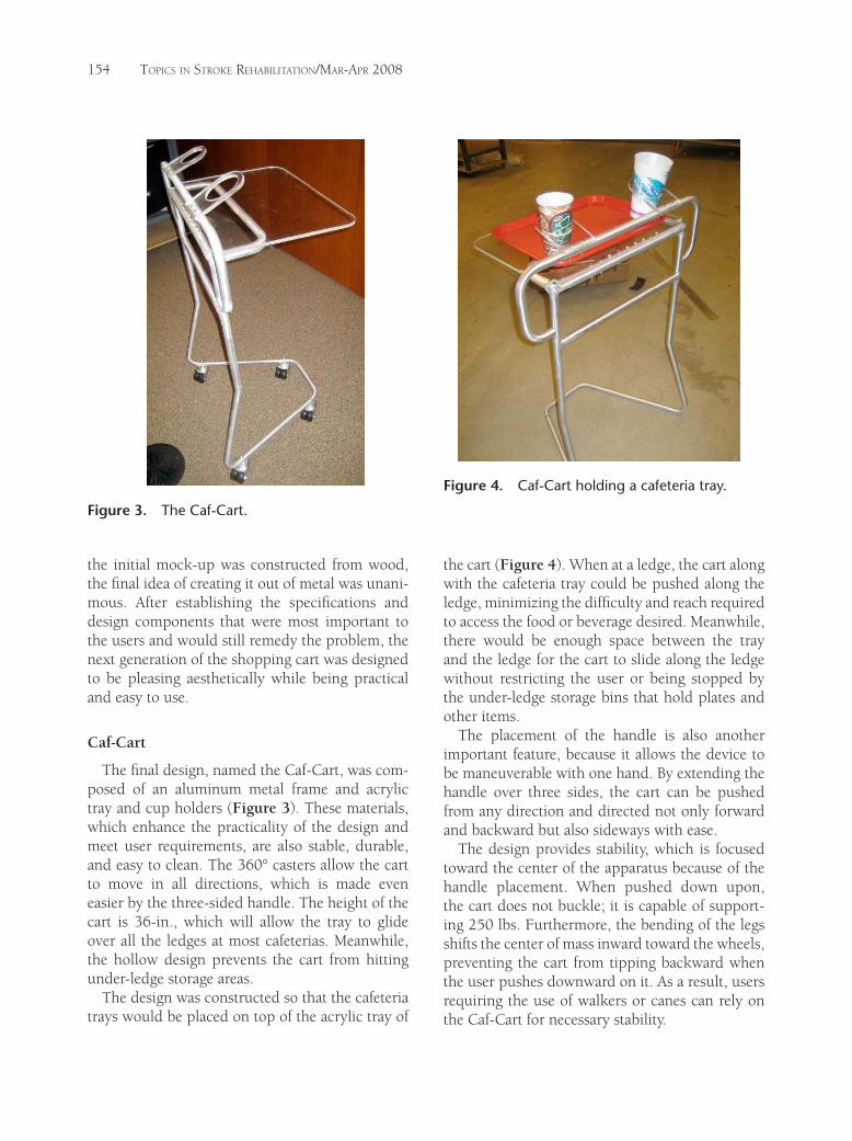
the initial mock-up was constructed from wood, the final idea of creating it out of metal was unani-mous. After establishing the specifications and design components that were most important to the users and would still remedy the problem, the next generation of the shopping cart was designed to be pleasing aesthetically while being practical and easy to use.
Caf-Cart
The final design, named the Caf-Cart, was com-posed of an aluminum metal frame and acrylic tray and cup holders (Figure 3). These materials, which enhance the practicality of the design and meet user requirements, are also stable, durable, and easy to clean. The 360° casters allow the cart to move in all directions, which is made even easier by the three-sided handle. The height of the cart is 36-in., which will allow the tray to glide over all the ledges at most cafeterias. Meanwhile, the hollow design prevents the cart from hitting under-ledge storage areas.
The design was constructed so that the cafeteria trays would be placed on top of the acrylic tray of
the cart (Figure 4). When at a ledge, the cart along with the cafeteria tray could be pushed along the ledge, minimizing the difficulty and reach required to access the food or beverage desired. Meanwhile, there would be enough space between the tray and the ledge for the cart to slide along the ledge without restricting the user or being stopped by the under-ledge storage bins that hold plates and other items.
The placement of the handle is also another important feature, because it allows the device to be maneuverable with one hand. By extending the handle over three sides, the cart can be pushed from any direction and directed not only forward and backward but also sideways with ease.
The design provides stability, which is focused toward the center of the apparatus because of the handle placement. When pushed down upon, the cart does not buckle; it is capable of support-ing 250 lbs. Furthermore, the bending of the legs shifts the center of mass inward toward the wheels, preventing the cart from tipping backward when the user pushes downward on it. As a result, users requiring the use of walkers or canes can rely on the Caf-Cart for necessary stability.
Figure 3. The Caf-Cart.
Figure 4. Caf-Cart holding a cafeteria tray.

Design of a Cafeteria Tray 155
This design has nesting ability, so the carts can compact into each other, much like a grocery cart at a neighborhood food market. The 4:1 nesting ratio maximizes the number of carts storable in a limited space while still making the carts easy to access. Furthermore, the universality of the cart is much more apparent than a basket or standard tray. It is capable of functioning in numerous caf-eterias due to its pleasant design, practicality, and ease of use.
Acknowledgments
This research was supported by the US De-partment of Education, National Institute on Disability and Rehabilitation Research, grant number H133B031127, through the Rehabilita-tion Research and Training Center on Technology Promoting Integration for Stroke Survivors: Over-coming Societal Barriers.

156
Development of a One-Handed Nail Clipper for Stroke SurvivorsChristopher Carhart, Rafal Ciechowski, Doug Groat, and Alyson Stevans
Due to the physical effects of stroke, many stroke survivors experience difficulty clipping their nails. Much of this difficulty is due to weakness in the upper extremities, loss of dexterity, spasticity, and vision problems. Our goal was to design a device that would help stroke survivors shorten their finger nails, providing increased independence, convenience, comfort, and safety compared to their current method of cutting nails. From user interviews and observations, we developed several prototypes to solve this problem. The final design, the Step ‘n Snip, consists of a finger nail clipper mounted on an inclined, rotatable metal rod. The clipper is attached to a foot pedal with a long steel bike brake cable, which the pedal then uses to actuate the clipper. The pedal is mounted on a base that is shaped such that it provides a nesting space for the clipper frame during storage; the two parts are kept together by a swiveling clip. The clipper itself is at a convenient height for users and is fitted with a nail clippings collection system. Key words: adaptive device, design, nail clipper, stroke
Engineering Design and Communication, Section 17, Team 2, Segal Design Institute in the McCormick School of Engineering at Northwestern University, Evanston, Illinois. Students: Christopher Carhart, Rafal Ciechowski, Doug Groat, and Alyson Stevans. Instructors: Michelle Greenberg and John Lake.
Our objective in designing the Step ‘n Snip was to create a fingernail shortening device that efficiently and comfortably
allows persons with any degree of limited arm and hand use in one side of their body to shorten their fingernails easily and independently. Most stroke survivors have near full dexterity in their strong hand, and many users have varying degrees of weakness and spasticity in their affected hand. This makes using conventional fingernail shorten-ing methods nearly impossible for many users. Current products are neither efficient nor effective in solving this problem.
There are many current fingernail shortening devices, geared mainly toward amputees, on the market that allow stroke survivors with some con-trol and flexibility in their affected arm to clip nails on their strong hand. However, no current devices are effective in clipping nails on both hands of us-ers with moderate to high spasticity in their weak hand or users with limited or no flexibility on their affected side. As a whole, currently available prod-ucts do not address the entire problem.
Our primary goal was to enable users of all degrees of flexibility and control in their affected side to clip their fingernails independently and efficiently in virtually any location. Our secondary goals were to make the product easily storable, portable, and relatively lightweight.
User Interviews
We interviewed several stroke survivors at the Rehabilitation Institute of Chicago to determine the problems associated with clipping fingernails and features that they wanted to see in the de-vice. The following are preferences that the users wanted to see in the nail clipper.
• Mobility. Users did not want the nail cutter to be stationary; they wanted to be able to easily store it in a drawer or closet. They also did not want the product to be too bulky.
• Efficiency. Users wanted a product that could cut nails quickly and easily.
• Nail collection. Users wanted a product that could collect the nail clippings.
• Safety. Users wanted a safe product that they would not be likely to injure themselves with.
Top Stroke Rehabil 2008;15(2):156–159© 2008 Thomas Land Publishers, Inc.www.thomasland.com
doi: 10.1310/tsr1502-156

One-Handed Nail Clipper 157
• Discreetness. Users did not want the product to obviously identify the user as having a dis-ability. They wanted the device to look aes-thetically pleasing, although this was less of a priority than the functionality of the design.
• Ease of operation. Users preferred an alterna-tive improved actuation method, such as the foot.
• Stability. Users wanted a device that did not have the risk of sliding on the table or counter while in use.
Competitive Products
We researched competitive products to see what was already available on the market. From this we could see whether existing designs might be modi-fied to address the new needs or how much they could be adapted or incorporated into our design. We found two devices already on the market.
Stapler one-handed device
This design consisted of a toenail-sized nail clip-per mounted on a small plastic base with rubber grips on the corners of the bottom side of the base. This allowed the user to position one hand to be clipped and to press down with the free hand. Most devices of this type are designed for amputees and do not address problems of weakness, spasticity, and lack of fine motor skills that are often found in stroke survivors.
Nail clippers/nippers
Nail clippers and nippers can be used to a lim-ited extent on the strong hand, due to the limited control in the weak hand.
Design Concepts
Implication for alternatives
All of the information we gathered from the user observations and product research gave us direc-tion in our design process. The following are the most important aspects that needed to be included in the design:
• Method of actuation. The users expressed willingness to explore alternative methods of
actuation, different from what their current devices employed.
• Stabilization. The issue of stabilization had two parts, one dealing with stabilization of the hand, and the other concerning keeping the device itself stationary during clipping. This required a way to counteract the spastic-ity of the hand and to incorporate an effective nonslip grip respectively.
• Independence. Both the user observations stressed that the device should be used with-out any outside help.
• Portability and storability. From the user obser-vations, we learned that it was important for the device to be mobile and easy to quickly set up and put away.
• Safety. From the user observation, we realized that fear of cutting the fingers of the weak hand is of great concern. We also learned that the users would like to get the fingernails on their affected hand more neatly clipped; however, they are unable to for fear of injury. Thus, the alternative concept had to be as safe as possible.
• Discreetness. From the user observations, we concluded that the users would like the prod-uct to be easily storable; the device should also look nice while not drawing extra atten-tion.
• Efficiency. From the user observations, we learned that the operation of the product needed to be improved. Therefore, it was imperative to explore different methods of actuation, such as using different parts of the body, for the alternative concepts.
Testing
We conducted user testing sessions to evaluate all four alternative design concepts. The users were asked to perform tasks that allowed the team to see if the user could properly set up each design, to see if the user could use the design, and to gather feedback from the user.
These tasks also allowed us to observe how in-tuitive and how feasible the set up was for a stroke survivor, to determine which features were neces-sary and which were not, and to establish what nail shortening methods worked.

158 TopicsinsTrokerehabiliTaTion/Mar-apr2008
Based on user test results, we focused on the foot pedal clipper design, the reason being that all the other mock-ups were determined to be either un-necessary or unacceptable. Both the finger mount and finger pivot were deemed unnecessary; the mouth clipper was out of the question upon the participants’ refusal to test it. It quickly became ap-parent that the best option to pursue was the foot pedal clipper, especially when one of the stroke survivors was able to clip his nails independently for the first time in years using the concept.
Some modifications to the foot pedal clipper included decreasing the dimensions of the base, testing different pedal styles and shapes, adding all of the improvements in the testing chart, and re-searching more methods for adding mobility to the nail clipper itself (such as left and right rotation).
Final Design
The final design, named the Step ‘n Snip, consists of a finger nail clipper mounted on an inclined, rotatable metal rod (Figure 1). The clip-per attaches to a foot pedal with a long steel bike brake cable, which the pedal then uses to actuate the clipper. The pedal is mounted on a base shaped such that it provides a nesting space for the clip-per frame during storage; the two parts are kept together by a swiveling clip. The clipper itself is at a convenient height for users and is fitted with a nail clippings collection system.
The user can adjust the rotational angle of the clipper, if desired, using the large black knob and set screw (Figure 2). Then the user places or guides the desired nail to be clipped into the clip-per and activates the clipper by pressing down on the foot pedal.
How the Step ‘n Snip meets the user requirements
• Clipping the strong hand. The foot pedal allows the users to have their strong hand free to guide itself into the clipping device for an easy and efficient cut.
• Clipping the spastic hand. The foot pedal allows the strong hand to guide each individual fin-ger on the spastic hand to the clipper blades. The adjustable rotation of the clipper allows
Figure 1. Overview of Step ‘n Snip.
Figure 2. Design in use.

One-Handed Nail Clipper 159
users of all levels of dexterity and spasticity to easily adjust the blades to line up with each nail.
• Easy storage and portability. The clipper base can be easily inserted into the pedal base and locked for compactness and easy portability. The design allows for simple, one-handed transport and manipulation of the device.
• Weight. The largest parts of the Step ‘n Snip are plastic, therefore the device is lightweight and can be easily lifted by most users.
• Nail collection. The Step ‘n Snip features a
modified nail collection system of a nail clip-per currently on the market.
Acknowledgments
This research was supported by the US De-partment of Education, National Institute on Disability and Rehabilitation Research, grant number H133B031127, through the Rehabilita-tion Research and Training Center on Technology Promoting Integration for Stroke Survivors: Over-coming Societal Barriers.