Embed Size (px)
Citation preview

1
An In vitro Model for a Cell Monolayer using a Microfluidic Device
Andrew Hartman, Materials Science and Engineering
Mentors: Brendan Leung, Joseph Labuz, & Cameron Yamanishi
Advisor: Shuichi Takayama
Introduction
Epithelium exist throughout the human body with varying purposes. These include the alveoli of
the lungs where gas exchange occurs, as well as the endothelial linings of the capillaries for
further gas exchange and waste transport. Monolayers also exist throughout the gut for nutrient
uptake as well as in the kidney for waste removal. Although single cell layers serve many vital
functions in the body, an in vitro model of the same conditions experienced in vivo has not yet
been designed. Monolayers are present in normal cell culture when growing cells on a dish, but
nowhere in the human body do cells exist on plastic. At all natural occurrences, monolayers exist
with fluid on either side, or fluid on one side and gas on the other. An in vitro design of cell
monolayers that is able to model the conditions found in vivo would therefore be incredibly
useful. Such a design would allow for a more realistic model for drug testing for pharmaceuticals
to be used where monolayers are present as well as in a larger project being worked on with the
end goal of modeling the human full metabolism in vitro.
Currently, cell monolayers, or sheets as we call them, can be formed with liquid on both sides,
although this is within a plastic tube. To accomplish this, an Aqueous Two-Phase System
(ATPS) is utilized [1]
. In our lab we accomplish this with a concentration of a sugar, Dextran
(DEX) for one phase, and the other with a high concentration of a polymer, Polyethylene Glycol
(PEG). When these two solutions are put in the same container, they separate, like oil and water
(Figure 1), and cells in the upper PEG layer will settle to the interface. With nothing at the
interface to bond to but themselves, the cells will form junctions with surrounding cells to form a
sheet. The issue with this set up is that once the cell sheet is formed within a tube, it is too fragile
to use. It is possible to empty the tube into a dish and remove the sheet, though the sheet is too
fragile to be moved from the dish. Furthermore, a high concentration of PEG will kill the cells if

2
left for more than 24 hours, so long term culture within the tubes is impossible. Therefore,
another system must be designed which can not only allow cell sheets to form, but keep them
alive long term and be easily accessible. Such a system would allow for further testing, staining,
and characterization.
My research goal was to design a system that could grow cell sheets as well as keep them alive
for an extended period of time and characterize sheets grown within this system. Extended
culture means that the PEG and DEX need to be removed from the sheet, and because the sheets
are too fragile to move out of their environment after growth, I would have to design a system
that can change the environment and medium around the cells. To do so, I designed a
microfluidic device.
Figure 1: top left a diagram of ATPS set up in a tube can be seen. Right an actual ATPS set up with a cell
sheet grown at the interface can be seen. Bottom Left the cell sheet from the image on the right can be
seen after it was removed from its tube. At this point it is too fragile for any further usage.

3
Chip Design
Microfluidic devices are typically made of Polydimethylsiloxane (PDMS), a transparent, flexible
polymer. My device consists of three individual pieces which are plasma bonded together into
one single chip Figure 2. Plasma oxidation removes the methyl group from a PDMS chain and
replaces it with a hydroxyl group. The resulting PDMS surface creates strong bonds with other
PDMS, creating one solid device
The design of the chip went through many different prototypes before the design seen above was
decided upon. This design allows for an ATPS to set up in the round middle chamber after the
Figure 2: left the three initial pieces of PDMS can be seen. The two top and bottom pieces are
identical with a microchannel molded into their surface. The middle slab has a 4mm hole punched
through it, which is where the cell sheet will form. These outside pieces are bonded to the middle
slab, with the channel on the inside, using a Femto Science Covance, with the round area of the
channel matching with the hole punched through the middle layer. Top Right a cross section of
the finished chip. The molded channels sit directly above the middle slab. The middle chamber
and top and bottom channels are now entirely inside the PDMS device. Bottom Right a finished
device.
4
PEG and DEX solutions are flowed in through the top and bottom channels respectively. Cells
are suspended within the top PEG layer so that they can settle to the interface and form a sheet.
The channels also allow for medium changes after the sheet has formed, so that the ATPS can be
removed. The wires seen in Figure 2 serve as electrodes to measure transepithelial electronic
resistance (TEER), which will be discussed in more detail later. The design of this device allows
for the environment to be changed around the cell sheet; as opposed to moving the sheet between
environments, which is difficult due to how fragile the sheet is.
Device Loading
To fill the device, a great amount of precision is needed. Ideally, the interface of the ATPS
would fall exactly in the middle of chamber. Top accomplish this, PEG would have to flow into
the top channel at the exact rate, starting at the exact same time as the DEX flowing into the
bottom channel. Because the liquid volume within the chamber is so small, approximately
0.0528 mL, the margin for error is very small. A syringe pump allows for constant, low flow
rates for multiple syringes, so that the interface can form as close to the middle of the chamber as
possible. Two syringes are used, one loaded with the DEX solution, and the other with the PEG
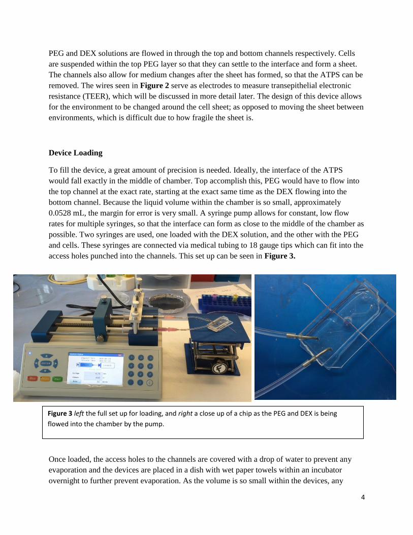
and cells. These syringes are connected via medical tubing to 18 gauge tips which can fit into the
access holes punched into the channels. This set up can be seen in Figure 3.
Once loaded, the access holes to the channels are covered with a drop of water to prevent any
evaporation and the devices are placed in a dish with wet paper towels within an incubator
overnight to further prevent evaporation. As the volume is so small within the devices, any
Figure 3 left the full set up for loading, and right a close up of a chip as the PEG and DEX is being
flowed into the chamber by the pump.

5
amount of evaporation will lead to air bubbles within the chamber that can interfere with sheet
formation and imaging. As the devices sit overnight, gravity leads to the cells falling to the
interface and forming a sheet.
Transepithelial Electronic Resistance (TEER)
TEER involves an electrical circuit with a cell monolayer as a part of the circuit. The resistance
across the monolayer can be used a quantitative measure of sheet quality. The more tightly
bonded the cells are, the harder it becomes for the current to pass through the junctions between
them. TEER is widely used to evaluate growing monolayers on trans well membranes [2]
, and
measurement devices are made specifically for this purpose. Commercially sold devices are
incompatible with our chip, since it required two electrodes to be submerged on either side of the
monolayer. Because the chip is a closed environment, we would have to design our own circuit
for measuring TEER. This is possible by measuring the voltage drop across the cell sheet
compared to a known resistor at different frequencies (an AC current is required as the cellular
membrane acts as a capacitor and would build up a charge in a DC circuit). The copper wires
seen protruding for the chip in Figure 2 are used as electrodes to connect the sheet into the
circuit. Special thin channels were designed into the chip to allow for the electrodes, which hook
the chip into a circuit, to be positioned into the edge of the chamber on either side of cell sheet.
We can then calculate the impedance of the cell sheet and in turn the resistance attributed to the
junctions between cells, our value of interest. The cell sheet includes two capacitive components
from the cell membrane, and two resistive elements from the cytosol as well as cellular
junctions. Through much circuit analysis the resistance of the junctions was calculated.
Figure 4: Left schematic of the chip being loaded with PEG and DEX flowing through the device. Right
cross section of a loaded chip with cells settled to form a cell sheet at the interface.

6
(
)
Where Z is the magnitude of the impedance of the sheet, K is a known constant, and f is the
frequency of the input signal at which measurements were taken. The circuit used to model our
set up can be seen in Figure 5.
Results
From the beginning of summer to the end of summer, protocol, chip design, and cell type used
all underwent changes. Initially, tests were conducted with MCF10a cells, which are human
breast epithelial cells. In the past at the lab, MCF10a sheets had been grown in tubes without
issue. Initial tests were done in chips with MCF10a but were never able to form full sheets
although control sheets in tubes formed normally. In chips, sheets only partially covered the
interface in wisps, seen in Figure 6. This sort of morphology is not possible for cells simply
settling to the interface; there is no reason for the cells to collect at these locations more than the
rest of the interface, as the surface is smooth with constant interfacial tension. It was theorized
that what was occurring was a complete cell sheet forming and bonding not only cell to cell, but
also cells to the outside of the chamber. The force of the cells pulling to the wall pulls the cells at
Figure 5 the circuit used for TEER readings.

7
the middle of the sheet apart, resulting in the stretched morphology we saw. This was confirmed
by a time course of images taken from 1 hour post seeding of cells through 24 hours seen in
Figure 7.
It was hypothesized that the pulling on the cells that occurred only in the chips was due to the
plasma oxidizing of the devices involved in their bonding. When PDMS is plasma treated it
Figure 6 The two images on the left show two chips imaged 24 hours post seeding which have pulled apart.
The image on the right is a well formed control sheet made the same day as the images on the left. Images on
the left taken at 2X using a Nikon overhead microscope and image compressor.
Figure 7 Time course of a single sheet forming. Images are taken at, from top left to bottom right: 1 hour, 2
hours, 4 hours, 8 hours, 12 hours, and 24 hours post seeding. Images are taken at 2X magnification with a
digital camera.

8
enables cells to adhere strongly to the treated PDMS, as well as the intended PDMS to PDMS
bonds. When the chips are being fabricated, all three pieces are exposed to plasma treatment to
ensure one solid device. Unfortunately, this also means the inside of the middle layer’s punched
hole is treated. To combat this, the end of a 4mm biopsy punch, the same punch used to cut the
chamber, was used to plug the hole in the middle layer of the device during treating and in turn
preventing the methyl groups from being replaced on the inside surface of the chamber.
Therefore, cells would not be as apt to adhere to the chamber well, and only bond with each
other.
Around the same time that this change was made, tests using MCF10a began failing, with the
control tubes no longer working either. Across the lab, other projects work with MCF10a, and at
the same time all MCF10a’s stopped working. Different MCF10a stocks were thawed from cryo-
freezing, but to no avail. What caused the MCF10a to stop working for everyone is still
unknown, but we were forced to change cells types to continue research. Fortunately, MCF10a is
not crucial to the project, just that an epithelial cell is used to form a cell sheet, as the end goal is
to form these same sheets with human lung cells. It was decided to proceed with canine kidney
epithelial tissue, MDCK.
MDCK yielded well-formed cells sheets immediately. Initial test were conducted in test tubes
ranging in inside diameter from 10mm down to 5mm, the smallest available to model the 4mm
chamber in the PDMS devices. Under all conditions, cell sheets formed, allowing research to
continue into the chips moving forward, where sheets also immediately formed. Unlike sheets
formed in tubes, these sheets did not cover the entirety of the interface (Figure 8). This
morphological difference, while unexpected is not detrimental to the integrity of the sheet. After
24 hours of formation in ATPS, the chips were again hooked up to the syringe pump, this time
loaded entirely with cell culture medium. After another 24 hours, the medium had changed from
its initial purple hue to a faint yellow due to phenol red indicator included in the medium which
changes to yellow in acidic conditions. This change in pH is attributed to cells using nutrients
and producing waste, indicating that the cells sheets are not only formed, but also still alive.
Figure 8 separate cells sheets formed in PDMS chips, imaged 24 hours post seeding. Note that although nearly
perfectly round, the sheets do not cover the entire interface. Images taken at 2X magnification with a digital camera.
9
To determine what leads to the morphological difference between sheets formed in tubes versus
sheets formed in chips, sheets were left to form in an Olympus inverted microscope, equipped
with a motorized stage and live cell imaging chamber to regulate temperature, CO2 levels and
humidity. The conditions in the live cell imaging chamber allow for sheets to form while be
imaged once every minute for 24 hours to create a time lapse movie of sheet formation. This
movie showed that, similarly to previous MCF10a sheets, the sheet initially formed across the
entire interface. Unlike previous tests through, within 30 minutes to an hour of seeding, the sheet
began to contract away from the chamber wall, uniformly. This is likely due to cells being less
apt to adhere to the non-plasma treated chamber wall, and instead only experiencing pulling
forces from other cells and tighter cellular junctions formed. Within 4 hours, all contraction had
stopped and the sheet reached its final morphology.
TEER Results
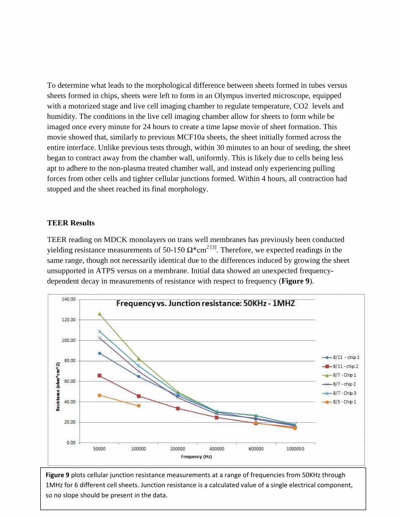
TEER reading on MDCK monolayers on trans well membranes has previously been conducted
yielding resistance measurements of 50-150 Ω*cm2 [3]
. Therefore, we expected readings in the
same range, though not necessarily identical due to the differences induced by growing the sheet
unsupported in ATPS versus on a membrane. Initial data showed an unexpected frequency-
dependent decay in measurements of resistance with respect to frequency (Figure 9).
Figure 9 plots cellular junction resistance measurements at a range of frequencies from 50KHz through
1MHz for 6 different cell sheets. Junction resistance is a calculated value of a single electrical component,
so no slope should be present in the data.

10
Each measurement, regardless of frequency, is a measure of the resistance through the same
sheet, and therefore measurements should be constant, not decaying as we see in Figure 9. After
going over our calculations finding junction resistance, it was determined that there must be an
additional circuit element which we are overlooking. Initially, resistance of a chip loaded with
only medium (negligible resistance) was measured to ensure that our setup was functioning
properly. These measurements were used to model the ATPS solution surrounding the cell sheet.
This was overlooking that ATPS has macromolecules suspended within it, as well as an interface
that could have an effect on the flow of current. To analyze these affects, chips were loaded with
various concentrations of ATPS as well as PEG and DEX only to see if these caused any
unexpected resistivity.
We expected to see an impedance element from the macromolecules of PEG and DEX
suspended within the medium, though we expected the interface to have no electrical effect. We
found that PEG and DEX solutions do impose an added impedance effect, but both of these in
the chip at once as an ATPS raises this impedance significantly, as can be seen in Figure 10.
Figure 10 When the chip was filled entirely with 10% PEG and 10%DEX, voltage drops were nearly
identical, but when the same two solutions were used in ATPS, the resulting voltage drop was
significantly higher with a different shaped curve. Because voltage drop is directly related to
impedance and resistance, it can be concluded that the interface of an ATPS adds an additional
resistive element.

11
Though work has not been done within the lab to characterize this added element due to ATPS, it
will be an interesting topic of study as the project continues. Zdenek Samec worked with similar
liquid-liquid interfaces in trying to characterize their properties [4]
. His research suggests that
such a system can be characterized as two resistive elements from the macromolecules in liquid
suspension in series with a capacitive element at the interface. It would seem as though our
system would fit this model, though further work will be done to fine tune our model based off
of this work.
Discussion
The recent findings regarding TEER as an additional electrical component are very exciting for
future research. With this information, we can integrate the interface as an added circuit
component and hopefully get accurate measurements of junction resistance, and in turn be able
to quantitatively describe the quality of the cell sheets. In the near future much of the work on
this project will be done to fine tune the TEER circuit analogy such that consistent data can be
collect without unexpected trends. Also, the interface of such an ATPS as an electrical circuit
component isn’t a topic with much previous work, which could lead to further applications
characterizing a relationship between interfacial tension and resistivity.
Within the lab, we will soon be moving away from MDCK for cell sheet formation to work with
the end goal of lung epithelium. Lung sheets will be used in a much larger project as an in vitro
model for the lung in the human on a chip project which aims to model the entirety of the human
metabolism on a microfluidic device for the purposes of drastically improving personalized
medicine. Previously in the lab, projects have been conducted to model the adipose and kidney
aspects of this future device. MDCK was used primarily as a model cell type to conduct many
experiments and fine tune protocol for forming and characterizing cell sheets. Not only is lung
more expensive to work with, but once work begins with a stock, it can only be passaged a finite
amount of times before it is no longer workable. Because of this, it is important to have all
aspects of cell sheet formation fine-tuned, so that, in theory, lung sheets can be made effectively
when we begin work on them.
Conclusion
Over the course of the summer, we were able to successfully design a microfluidic system
capable of growing a cell sheet. We were able to fine tune the protocol for growth and begin tests
to characterize the sheets. Most characterization work was devoted to developing a circuit for
TEER testing and analyzing these results. While TEER testing is not complete, it lead to a new
discovery regarding the interface as an electrical circuit component, which will be the focus of
much research in the future. We were also able to begin testing on the long term survival of the

12
sheets, which was initially promising. More work will be required though, to design a way to
catch the cell sheet when ATPS is removed, because when replaced with medium, the cell sheet
falls to the bottom of the chamber as there is no longer an interface to support it. This should be
able to be solved by altering the design of the middle chamber. In the future, our primary goal
will be to grow the cell sheets within a chip using lung tissue. Once this is accomplished, we will
move on to characterizing these sheets through imaging and TEER measurement techniques
developed over the summer.
References
1. Rajni Hatti-Kaul. “Aqueous Two Phase Systems: A general overview.” Molecular
Biotechnology. 2001, Vol. 19.
2. Kathryn Hatherell. “Development of a three-dimensional, all-human in vitro model of the
blood–brain barrier using mono-, co-, and tri-cultivation Transwell models.” Journal of
Neuroscience Models. 2011, Vol. 199.
3. Nicholas J Douville. “Fabrication of Two-Layered Channel System with Embedded
Electrodes to Measure Resistance across Epithelial and Endothelial Barriers.” Anal
Chem. 2010 March 15; 82(6).
4. Zdenek Samec. “Electrical Double Layer at the Interface between Two Immiscible
Electrolyte Solutions.” Chemical Reviews. 1988, Vol. 18, No.4.