Embed Size (px)
Citation preview

0885-8993 (c) 2020 IEEE. Personal use is permitted, but republication/redistribution requires IEEE permission. See http://www.ieee.org/publications_standards/publications/rights/index.html for more information.
This article has been accepted for publication in a future issue of this journal, but has not been fully edited. Content may change prior to final publication. Citation information: DOI 10.1109/TPEL.2020.3009619, IEEETransactions on Power Electronics
An improved voltage-shifting strategy to attainconcomitant accurate power sharing and voltage
restoration in droop-controlled dc microgridsWaner Wodson A. G. Silva, Student Member, IEEE,, Thiago R. Oliveira, Member, IEEE, and
Pedro F. Donoso-Garcia
Abstract—This work proposes a distributed secondary levelcontrol strategy for dc microgrids, which achieves accurateand proportional power sharing and dc bus voltage deviationrestoration based on voltage-shifting. In contrast to similarapproaches, only one variable per converter is transmitted in thelow-bandwidth communication link and with a simple integratoras the secondary level controller both objectives are achievedsimultaneously. The information state shared between convertersis a λ factor that incorporates the converter output voltage andpower information. The secondary control computes the averageλ locally and the controller generates an unique voltage-shiftingterm that modifies the converter output voltage reference. Whenall converters’ λ converge to the average value, both proportionalpower sharing and dc bus voltage restoration are attained. Theproposed technique suppresses the need for a complex controlstructure and large amount of converter variables. The proposedcontrol is evaluated through PLECS simulation and it is validatedin a 6.4 kW dc microgrid setup.
Index Terms—DC microgrid, accurate power sharing, voltagerestoration, voltage-shifiting, distributed control.
I. INTRODUCTION
THE microgrid (µG) concept is a solution for the integra-tion of multiple renewable energy sources and energy
storage systems into the grid, enabling local resources tobe clustered together and operate either islanded or grid-tied, thus providing more flexibility and resilience to theelectrical system [1]–[3]. Recently, DC-µGs have becomemore prominent due to their advantages over AC-µGs [4], e.g.,simplified power control, since there is no reactive power flow,phase synchronization and ac power quality issues [5], [6].Moreover, since most renewable sources and storage devicesexhibit a dc output, interfacing them to the main bus of a DC-µG requires less power conversion stages, thus leading to amore efficient approach [4], [5], [7], [8].
Fig. 1 depicts a typical DC-µG architecture for buildings,along with its main elements: a Bidirectional Interface Con-
Waner Wodson A. G. da Silva is with the Federal University of Itajuba(UNIFEI), Itabira, Brazil, e-mail: [email protected].
Thiago R. Oliveira is with Electronic Engineering Department, FederalUniversity of Minas Gerais (UFMG), Belo Horizonte, Brazil, e-mail: [email protected]
Pedro F. Donoso-Garcia is with the Electronic Engineering Department,Federal University of Minas Gerais (UFMG), Belo Horizonte, Brazil, e-mail:[email protected]
This work was supported in part by the Universidade Federal de Itajuba(UNIFEI) and in part by Universidade Federal de Minas Gerias (UFMG).
220 Vrms
RRC
BIC
utility grid
C
load
loadESC communication
power flow
Fig. 1. DC microgrid for buildings.
verter (BIC), which is responsible for interfacing the main dcbus and the utility grid at a point of common coupling (PCC), aRenewable Resource Interface Converter (RRC) and an EnergyStorage Interface Converter (ESC), which are responsible forinterfacing the distributed generation and storage to the dcbus, respectively. Another common element to µGs is thecommunication network, which is generally used to implementa hierarchical control strategy that operates at different timescales to achieve multiple control goals [3]. A 380 V dc bus isthe system backbone, interlinking all µG converters and loads.The µG’s control is divided into layers, where the primarylayer is commonly implemented with a droop technique toachieve decentralized power sharing, high reliability, flexibil-ity, expandability and plug-and-play capability for the DC-µG [3], [9]–[11]. The secondary control layer is responsiblefor ensuring that the electrical values of the µG are withinpredefined ranges, thus providing means for correcting errorseventually introduced by the primary layer [1], [12].
In spite of its advantages, droop control has limitationssuch as the existence of a trade-off between tight voltageregulation and accurate power sharing as well as power sharingbeing strongly influenced by line impedances [11], [13]–[15].In order to compensate the dc bus voltage deviation and tocorrect power imbalances, the secondary control must modifyprimary level parameters based on the information exchangedamong the µG components through the system communicationnetwork [16]. Generally, the implementation of the secondarycontrol strategy can be centralized [9], [17] or distributed[18]–[20]. Centralized techniques, however, provide reducedreliability, since the central controller imposes a single point of
Authorized licensed use limited to: Thiago Oliveira. Downloaded on July 31,2020 at 19:12:11 UTC from IEEE Xplore. Restrictions apply.

0885-8993 (c) 2020 IEEE. Personal use is permitted, but republication/redistribution requires IEEE permission. See http://www.ieee.org/publications_standards/publications/rights/index.html for more information.
This article has been accepted for publication in a future issue of this journal, but has not been fully edited. Content may change prior to final publication. Citation information: DOI 10.1109/TPEL.2020.3009619, IEEETransactions on Power Electronics
failure (SPoF). Therefore, distributed control methods becomea more appealing option [17], [18], [21].
Voltage restoration is usually achieved by a voltage-shiftingvalue added to the voltage reference of the converters’ voltagecontrol loop. Power sharing correction, on the other hand,can be achieved by (i) droop coefficient adjustment or by(ii) voltage-shifting. The methods based on (i) [11], [16],[22]–[26] modify the droop coefficient in order to compensatefor the line impedance influence. However, system dynamicsare also affected and hence changes in the droop coefficientshould be limited in order to prevent instability. The controltechniques based on (ii) [3], [5], [7], [18], [27]–[34] usuallyrely on two control loops to define the total voltage-shiftingterm. The first loop is responsible for voltage restoration,whilst the second loop enforces power sharing. In addition,information shared between converters comprises at least oftwo parameters: the local dc bus voltage and the outputcurrent/power.
Another approach is to use only one control loop at thesecondary level in order to achieve power sharing and voltagerestoration simultaneously. In [35]–[37], the proposed tech-niques consist of only modifying the droop coefficient toachieve power sharing and, by decreasing its value, the voltagedeviation is reduced, but a steady state error will be present inthe dc bus voltage. In [20], [38], voltage-shifting is performedbased on the average value of the converters’ output currents,load sharing is reached and voltage deviation is improved dueto the attenuation of the droop effect, however, the averagebus voltage is not corrected.
In [2], [39], [40], secondary control strategies for attainingpower sharing and voltage restoration are proposed for isolatedµGs. In these proposals, each converter conveys informationabout just one parameter with its neighbors and receivesthe dc bus voltage informed by a common meter. In spiteof good performance, the use of a common measurementintroduces a SPoF and reduces reliability and expandabilityof the µG. In [41], [42], the control technique is also basedon only one variable exchanged between converters. In theseapproaches, the proportional power sharing control is realizedthrough a distributed consensus-based algorithm, whereas volt-age restoration is achieved in a decentralized manner, whereeach converter compensates its own droop voltage. However,as mentioned in [42], a steady state error in the average dcbus voltage will always be present.
The objective of this work is to propose a consensus-based distributed secondary control strategy based on voltage-shifting that is able to attain proportional power sharing anddc bus voltage restoration simultaneously. Unlike previousworks, where a set of electrical parameters is exchangedamong the converters through the communication network,the proposed technique relies on a single information calledthe λ factor, which is calculated based on the convertersoutput power and measured dc bus voltage. Periodically, eachconverter computes its own λ and broadcasts it to neighboringconverters through a low bandwidth communication (LBC)link. Locally, a converter employs the received information
Vo1
Rd1
io1
DC bus
r1
R
i
Vo2
Rd2
io2
r2v
**
Rd2+r2
Rd1+r1
Rd1=Rd2
Vo*
io1io2
vo1
vo2
v
v
i
vo1 vo2
a) b)
G
G
G
G
Fig. 2. Simplified model of a dc microgrid.
to determine an average λ and with that the voltage-shiftingcorrection term is generated by means of a simple unity-gain integrator as the secondary layer compensator. It willbe shown that as the system gradually reaches consensus,i.e., it converges to an average global λ, proportional powersharing and dc bus voltage restoration are achieved. The totalnumber of neighbors seen by a converter is determined in everycontrol cycle by the number of λ received, thus, the algorithmcan deal with dynamic changes in the µG configuration andcommunication failures, providing plug-and-play capabilityand flexibility. Moreover, the proposed technique eliminatesthe necessity for designing and decoupling multiple secondarycontrol loops, employing dc bus voltage observers or commonpoint measurement, while also reducing the information traffic.At last, a comparison of the main features of the proposedtechnique with other consensus-based algorithms available inliterature is provided in Tab. I.
This paper is outlined as follows: Section II discussesthe voltage-shifting influence on power/current sharing andvoltage restoration. Section III presents the proposed dis-tributed control technique. Section IV analyzes the systemvoltage stability. Section V and VI present the simulation andexperimental results, respectively, and the paper conclusionsare shown in Section VII.
II. VOLTAGE-SHIFTING INFLUENCE ON POWER SHARINGAND VOLTAGE DEVIATION IN DROOP CONTROLLED µGS
Consider the simplified model of a µG dc bus, presentedin Fig. 2.a. It is composed by two converters (Conv-1 andConv-2), represented by their steady state Thevenin equivalentcircuit, where V ∗
o1 and V ∗o2 are the nominal reference voltages,
Rd1, Rd2 are the droop resistances or droop coefficients,vo1, vo2, io1, io2 are the converters’ output voltage andcurrent, respectively, r1, r2 are the line resistances, RµG is themicrogrid load and vµ is the load voltage. Assuming that theconverters are equal, thus, V ∗
o1 = V ∗o2 = V ∗
o , Rd1 = Rd2 andr1 6= r2, Fig. 2.b shows the converters droop characteristic,considering the influence of r1 and r2.
Based on Fig. 2.a, it can be defined
io1 =V ∗o1(Rd2 + r2) +RµG(V ∗
o1 − V ∗o2)
α+ βRµG
io2 =V ∗o2(Rd1 + r1) +RµG(V ∗
o2 − V ∗o1)
α+ βRµG
(1)
Authorized licensed use limited to: Thiago Oliveira. Downloaded on July 31,2020 at 19:12:11 UTC from IEEE Xplore. Restrictions apply.

0885-8993 (c) 2020 IEEE. Personal use is permitted, but republication/redistribution requires IEEE permission. See http://www.ieee.org/publications_standards/publications/rights/index.html for more information.
This article has been accepted for publication in a future issue of this journal, but has not been fully edited. Content may change prior to final publication. Citation information: DOI 10.1109/TPEL.2020.3009619, IEEETransactions on Power Electronics
TABLE I: Main features of consensus-based secondary control algorithms for voltage restaoration and power-sharing.
Literature Information Sec. ctrl. loops Meth. Comments
[43] v s u multiple vs utilizes the tertiary control to achieve multiple objectives[3], [18], [32],
[34], [44], [45]v i multiple vs employs two PI compensators: one to restore the average voltage and other for
current sharing[23] v i multiple da two PI compensators: one to restore the average voltage and other for droop
adjustment[30] v,i dV/dt multiple vs three control loops: besides the voltage and current average comtrol loops the
third is for sharing the dynamic voltage[27], [29] v i multiple vs employs one PI compensator where the input is a sum of the outputs of I
compensator for average voltage and P compensator for average current[41] i 1/rij single vs voltage deviation correction is decentralized. However, prior knowledge of the
µG configuration is required. P&P is not ensured, since consensus algorithmcoefficients are based on the line conductances 1/rij
[42] power multiple da voltage deviation correction is decentralized.Proposed tech-nique
λ single vs employs just one unity-gain integrator, attains power sharing and voltagerestoration simultaneously and does not require prior knowledge of the µGconfiguration.
meth.: correction method, where vs is voltage-shifting and da is droop-adjustment. P&P: Plug-and-play capability
whereα = (Rd1 + r1)(Rd2 + r2)
β = Rd1 +Rd2 + r1 + r2.(2)
Conv-1 and Conv-2 output voltages are expressed by (3) andthe average value between them is defined in (4).
vo1 = V ∗o1 −Rd1io1
vo2 = V ∗o2 −Rd2io2
(3)
voavg =vo1 + vo2
2(4)
The voltage deviation can be reduced by a voltage-shiftingvalue (δvavg), which is added to the voltage reference (V ∗
o +δvavg) of each converter, so that voavg = V ∗
o . Replacing (1)and (3) in (4), δvavg can be defined as
δvavg =2Rd1Rd2 +Rd1r2 +Rd2r1
2(βRµG + r1r2) +Rd1r2 +Rd2r1V ∗o . (5)
Considering (1), the output current imbalance can be calcu-lated as follows
∆io = io1 − io2 = ...
2(V ∗o1 − V ∗
o2)RµG + (Rd2 + r2)V ∗o1 − (Rd1 + r1)V ∗
o2
α+ βRµG.
(6)
It indicates that if appropriate voltage-shifting terms δv∆i1
and δv∆i2 are used to adjust V ∗o1 and V ∗
o2, respectively, thecurrent sharing error can be mitigated. Therefore,
V ∗o1 = V ∗
o + δvavg + δv∆i1
V ∗o2 = V ∗
o + δvavg + δv∆i2.(7)
However, according to (6), r1 < r2 implies in δv∆i1 <δv∆i2, thus, ∆io = 0 leads to voavg 6= V ∗
o . Otherwise,δv∆i2 > 0 and δv∆i1 = −δv∆i2, implies in ∆io 6= 0 and
voavg = V ∗o . It is concluded that r1 6= r2 precludes achieving
concomitant voltage regulation and balanced output currents.One can express the converters’ output power imbalance as
∆po = po1 − po2 = vo1io1 − vo2io2. (8)
Assuming a condition where δv∆i1 = −δv∆i2 = δv∆i andreplacing (1), (3), (5) and (7) in (8), it is obtained ∆po as afunction of δv∆i :
∆po(δv∆i) = a(δv∆i)2 + b(δv∆i) + c (9)
where the coefficients a, b and c are defined in (10) withRtj = Rdj + rj + 2RµG for j = 1, 2.
The converters output power are po1 = vo1io1 and po2 =vo2io2, so that, ∆io = 0 results in po1 < po2. For the conditionwhere δv∆i1 = −δv∆i2 = δv∆i and ∆po(δv∆i) = 0,it implies in ∆voio2 = ∆iovo1, producing po1 = po2,hence, it is possible to achieve simultaneous power sharingand regulated dc bus voltage by using a voltage-shiftingterm δvV = δvavg ± δv∆i. It is noteworthy that, since lineresistances are not compensated, a small error between voavgand vµ is expected.
III. PRINCIPLE OF THE PROPOSED STRATEGY
The proposed technique aims at computing a single voltage-shifting term (δvV ), for each converter, that promotes accurateand proportional power sharing and dc bus voltage restoration.A LBC network is used to exchange information betweenneighboring converters and a consensus-based algorithm isemployed to converge the information state to an averagevalue. However, unlike previous proposals, where multipleconverter measurements are exchanged in the LBC link andmultiple control loops are required to compose the properδvV , the technique proposed herein defines a factor (λ) as theinformation state instead, which is computed locally by each
Authorized licensed use limited to: Thiago Oliveira. Downloaded on July 31,2020 at 19:12:11 UTC from IEEE Xplore. Restrictions apply.

0885-8993 (c) 2020 IEEE. Personal use is permitted, but republication/redistribution requires IEEE permission. See http://www.ieee.org/publications_standards/publications/rights/index.html for more information.
This article has been accepted for publication in a future issue of this journal, but has not been fully edited. Content may change prior to final publication. Citation information: DOI 10.1109/TPEL.2020.3009619, IEEETransactions on Power Electronics
a =Rd2R
2t1 −Rd1R
2t2 + (α+ βRµG)(Rd2 −Rd1 + r2 − r1)
(α+ βRµG)2
b = V ∗o
((Rd2 + r2)(2Rd1Rt2 − α− βRµG)− (Rd1 + r1)(α+ βRµG − 2Rd2Rt1)− (β + 4RµG)(α+ βRµG)
(α+ βRµG)2
)
c = V ∗2o
(α+ βRµG)(Rd2 −Rd1 + r2 − r1) +Rd2(Rd1 + r1)2 −Rd1(Rd2 + r2)2
(α+ βRµG)2
(10)
converter, according to (11), where voj is the j-th converteroutput voltage and P oj is a power quantity defined as (12),where poj is the converter output power, and Pjmax is its ratedpower. The gain 1/2 is needed to avoid a division by zero inthe local controller when poj = Pjmax.
λj = P ojvoj (11)
P oj = 1− 1
2
pojPjmax
(12)
During a control cycle, each converter sends its λ factor toits N neighbors and receives their respective λ factors, throughthe LBC network. Afterwards, it locally computes a voltage-shifting term as
δvV j =
∫ (V ∗o −
λavg
P oj
)dt (13)
where, V ∗o is the dc bus voltage reference and λavg is the
average λ, defined as
λavg =λ1 + λ2 + · · ·+ λN
N(14)
In order to deal with communication failures and theaddition/removal of new agents, the algorithm defines N asthe number of neighboring converters that send informationto the j-th converter in a control cycle. The proposed localcontroller diagram is shown in Fig. 3, where Cv and Ciare the voltage and current loop PI (proportional-integral)compensators, respectively, Rdj is the droop coefficient andlowpass filters were used to smooth the output current andpower measurements. Assuming, for the sake of argument,that the secondary control strategy is able to converge, thenV ∗o =
λavg
P o1=
λavg
P oN, through (11), (12) and (14) it can be
shown that a convergence of δvV will lead to
po1P1max
=po2
P2max= · · · = poN
PNmax
V ∗o =
vo1 + vo2 + · · ·+ voNN
(15)
Although there is a single secondary control loop, powersharing and voltage restoration exhibit different time constants.The convergence analysis of each control objective will beaddressed separately in the following subsections.
i*
droop
controller
current
loopi
Ci
vsource voj
ioji
Cv
voj
Vo*
iojvoltage
loop
ioj
Poj
voj
primary
control
Rdj 1
voj
j
Poj
LBC
12
1Pmax
Fig. 3. Diagram of the proposed control.
A. Power sharing convergence analysis
Assuming that the control cycle, i.e., the sampling timeof the secondary control layer (tδvV ), is much greater thanthe primary control bandwidth, the dynamic behavior of theproposed strategy can be studied considering the simplified µGmodel of Fig. 2.a. Applying (13) to V ∗
o1 and V ∗o2 results in a set
of nonlinear differential equations, with no explicit analyticalsolution, thus, the system response can only be assessed bynumerical analysis. Evaluating several scenarios with the aidof numerical simulations, it was observed that the powerimbalance behavior exhibits a second order system response,which is influenced by the load, droop and line resistances andtδvV as well. Interestingly, when the converters comply withRd1P1max = Rd2P2max, two different scenarios will exhibitthe same dependency on the normalized load power and tδvVif both also exhibit the same load type (resistive or constantpower load (CPL)) and the same kβ , where
kβ =Rd1 +Rd2 + r1 + r2
Rd1 +Rd2(16)
Therefore, the performance of multiple scenarios can bestudied by evaluating how changes in kβ impact the systembehavior. Notice that the greater the kβ , the more significant
Authorized licensed use limited to: Thiago Oliveira. Downloaded on July 31,2020 at 19:12:11 UTC from IEEE Xplore. Restrictions apply.

0885-8993 (c) 2020 IEEE. Personal use is permitted, but republication/redistribution requires IEEE permission. See http://www.ieee.org/publications_standards/publications/rights/index.html for more information.
This article has been accepted for publication in a future issue of this journal, but has not been fully edited. Content may change prior to final publication. Citation information: DOI 10.1109/TPEL.2020.3009619, IEEETransactions on Power Electronics
(a) Influence of tδvV on root loci. (b) Influence of tδvV on Settling time.
(c) Influence of the load on the root loci. (d) Influence of the load on the Settling Time.
Fig. 4. Assessment of the power sharing behavior. In (a) and (b), tδvV varies from 1 ms to 60 ms. In (c) and (d), PLoad varies from 1 p.u. to 0.1 p.u.
are the line resistances in relation to the virtual droop resis-tances. In order to quantify the system performance in eachscenario, a process estimation function was used to estimatea second order system model from the numerical simulationdata. Fig. 4 presents the root loci and settling time responseof the estimated second order model against tδvV and the loadpower for a µG with resistive load and CPL as well.
It can be noticed that, for very low tδvV , the system showsa dominant pole that will grant it a first order behavior. AstδvV increases, system damping is decreased, reducing thepower sharing settling time (∆tps), but as the poles becomecomplex and move towards the RHS of the s-plane, ∆tpsalso increases. Eventually, for large tδvV , the system becomesunstable, e.g., for kβ ≈ 1, critical stability is reached attδvV ≈ 65ms. An increase in kβ as well as a decrease inthe load power raises system damping, reducing ∆tps forcomplex poles and the contrary for real poles. It is also noticedthat in the load variation range, ∆tps varied roughly 6dB,whereas in the tδvV range, it varied up to 35dB, hence, properselection of tδvV is crucial for the successful operation of theµG. It is noteworthy that, although small differences can beobserved between the resistive and CPL behaviors, both typesperformed similarly. Since the proposed strategy does not alterthe output impedance of the converters, once the primary levelis designed to ensure a stable operation in the presence of CPL,the secondary layer will not degenerate the load dynamics.
B. Average voltage convergence analysis
Once power balancing is achieved, the secondary-layercontrol feedback will become
P ovo1 + P ovo2
2P o=vo1 + vo2
2= voavg. (17)
Consequently, the secondary control law can be rewritten as
δvV j(t) ≈∫
(V ∗o − voavg(t)) dt (18)
Assuming that ∆tps is negligible in relation to the voltagerestoration response, replacing (18) in (1)-(4), yields
voavg(t) = V ∗o (1− kvo) e−(1−kvo)t
kvo =Rd1(Rd2 + r2) +Rd2(Rd1 + r1)
2(α+ βRµG)
(19)
Therefore, the dc bus voltage restoration will show a firstorder response with a time constant τv = (1− kvo)−1. Obvi-ously, ∆tps << τv is required. Fig. 5 illustrates the transientresponse of the proposed technique, for a simplified dc µGmodel with the parameters given in Tab. II and RµG = 40Ω,which leads to a τv ≈ 1s and ∆tps ≈ 0.176s.
It can be seen that before the secondary control strategy isenabled, the µG operates with voavg ≈ 370V , a load voltageof 369V and a power mismatch of 0.13 p.u. In t = 0.5s thesecondary control is activated. It can be noticed that at first,the voltage-shifting terms δvV 1 and δvV 2 are predominantly
Authorized licensed use limited to: Thiago Oliveira. Downloaded on July 31,2020 at 19:12:11 UTC from IEEE Xplore. Restrictions apply.
0885-8993 (c) 2020 IEEE. Personal use is permitted, but republication/redistribution requires IEEE permission. See http://www.ieee.org/publications_standards/publications/rights/index.html for more information.
This article has been accepted for publication in a future issue of this journal, but has not been fully edited. Content may change prior to final publication. Citation information: DOI 10.1109/TPEL.2020.3009619, IEEETransactions on Power Electronics
Fig. 5. Evolution of δvV and its effect on bus voltage and power imbalance.
defined by δv∆i, hence they diverge from each other, forcingthe output power imbalance to be mitigated in ∆tps = 0.176s.Once po1 = po2, the argument of the secondary control integralaction of both converters is the same, therefore the voltage-shifting terms evolve defining a δvavg that leads the dc busvoltage to converge to voavg = 380V in ∆t = 5τv ≈ 5s. Insteady state, δv∆i2 = −δv∆i1 = 1.035V and δvavg = 9.665V .
Since the electrical and communication systems interactwith each other, they are affected by the transmission rateand communication network configuration [3]. Therefore, it isimportant to consider the discrete nature of the communicationnetwork, hence the secondary layer integral controller isimplemented in discrete time, where the time interval betweencontrol cycles (tδvV ) should be enough for all converters tosend and receive the λ factors and update δvV .
IV. STABILITY ANALYSIS
From the µG model in Fig.2, the relationship between theoutput voltage and current of Conv-1 can be expressed as:
io1 = γvo1 − κvo2 (20)
whereγ =
r2 +Rµr1r2 + r1RµG + r2RµG
κ =RµG
r1r2 + r1RµG + r2RµG
(21)
Replacing δvavg + δv∆i for δvV 1 in (7) and in (3) yields
vo1 = V ∗o + δvV 1 −Rd1io1 (22)
Considering (13) and (20)-(22), the closed-loop control dia-gram of Conv-1 is shown in Fig. 6. Assuming that tδvV is much
G
S
1
Vo*
vo2
vo1 io1
Rd1
1/2
Po1
Po1
1
Gvo
GLPF2nd layer
1st layer
vo2Po2
Fig. 6. Closed-loop control diagram for stability analysis.
larger than the converter local control response time, thenthe converter could be represented by its Thevenin equivalentcircuit. The communication delay is represented by e−τds andthe closed-loop transfer function is expressed as [5], [7]:
Gvo =GPIGC
1 +GPIGC(23)
where GPI and GC are the voltage loop PI compensator andthe current loop transfer function, respectively. GC can berepresented as a delay unit [7]. Therefore, from Fig. 6, Conv-1 output voltage is expressed as:
vo1 =
[V ∗o (1 + 1/s) + vo2(κRd1GLPF − e−τdsP o2
2P o1s)]Gvo
1 + (γRd1GLPF + e−τds
2s )Gvo(24)
where GLPF = 2πfcs+2πfc .
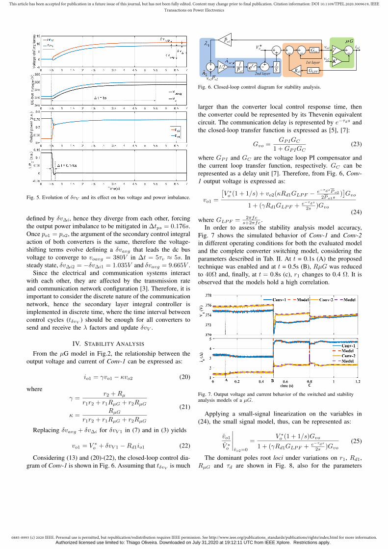
In order to assess the stability analysis model accuracy,Fig. 7 shows the simulated behavior of Conv-1 and Conv-2in different operating conditions for both the evaluated modeland the complete converter switching model, considering theparameters described in Tab. II. At t = 0.1s (A) the proposedtechnique was enabled and at t = 0.5s (B), RµG was reducedto 40Ω and, finally, at t = 0.8s (c), r1 changes to 0.4 Ω. It isobserved that the models hold a high correlation.
Fig. 7. Output voltage and current behavior of the switched and stabilityanalysis models of a µG.
Applying a small-signal linearization on the variables in(24), the small signal model, thus, can be represented as:
vo1
V ∗o
∣∣∣∣∣vo2=0
=V ∗o (1 + 1/s)Gvo
1 + (γRd1GLPF + e−τds
2s )Gvo(25)
The dominant poles root loci under variations on r1, Rd1,RµG and τd are shown in Fig. 8, also for the parameters
Authorized licensed use limited to: Thiago Oliveira. Downloaded on July 31,2020 at 19:12:11 UTC from IEEE Xplore. Restrictions apply.

0885-8993 (c) 2020 IEEE. Personal use is permitted, but republication/redistribution requires IEEE permission. See http://www.ieee.org/publications_standards/publications/rights/index.html for more information.
This article has been accepted for publication in a future issue of this journal, but has not been fully edited. Content may change prior to final publication. Citation information: DOI 10.1109/TPEL.2020.3009619, IEEETransactions on Power Electronics
described in Tab. II. To verify the influence of line impedanceon the closed-loop system poles, r1 varies from 0.05Ω to 1Ωand r2 is fixed. Rd1 varies from 0.5Rd1 to 2Rd1 with Rd2
fixed and RµG is varied from 0.5RµG to 1000RµG, whichallows to evaluate the conditions from heavy µG load upto light load. The effect of λavg calculation delay (τd) wasassessed considering tδvV as a reference, therefore, τd wasvaried from 1ms to 100ms. In all four analyzes, the poles lociwere affected, however, in the considered variation ranges nosmall-signal instability is foreseen. It is noticed, as it is thecase for consensus-based algorithms, that time delay producescomplex poles and its increase shifts them towards the RHSof the s-plane, reducing damping, as also discussed in [42].
-8000 -7000 -6000 -5000 -4000 -3000 -2000 -1000 0Real axis
-2000
-1500
-1000
-500
0
500
1000
1500
2000
Imagin
ary
axis
d increase
RG
increase
Rd1
increase
d increase
r1 increase
Fig. 8. Stability analysis of the converters.
A. Stability Analysis Generalized for N converters
Assuming the circuit of Fig. 2.a, now with N converters onthe dc-bus, then the output current in each converter can be
TABLE II: STABILITY ANALYSIS PARAMETERS
Item Symbol Value
Nominal voltage V ∗o 380V
Line impedance r1,2 0.1, 0.9Ω
Droop Coefficient Rd1,2 1.54, 3.08Ω
Load resistance RµG 80Ω
Integrator time interval tδvV 30ms
Calculation delay τd 1...100ms
LPF cut-off frequency fc 1.5kHz
G
S
1
Vo*
vo2
vo1 io1
Rd1
1/N
Po1
Po1
1
Gvo
GLPF2nd layer
1st layer
voN
Fig. 9. Control diagram for stability analysis for N converters.
r2
RL1
Conv-3 Conv-2 Conv-1
DC bus
LBC
vo3 vo2
vo1
RL2RL3
r3
r1
Fig. 10. Simulated DC microgrid.
calculated in matrix form: [R]
[io] = [vo]→RµG + r1 RµG . . . RµGRµG RµG + r2 . . . RµG
......
......
RµG RµG . . . RµG + rN
io1io2...ioN
=
vo1vo2
...voN
(26)
The closed-loop control diagram of Conv-1 with N con-verters can be represented by Fig. 9, where γj,k is an elementof matrix [γ] and [γ] = [R]−1. Considering (25), γ becomesγ1,1, hence, it is concluded that the effect of adding/removingconverters on stability is similar to the effect of Rd1 variation.
V. SIMULATION RESULTS
In order to evaluate the proposed method, a computationalsimulation of a dc microgrid with three Dual Active Bridge(DAB) converters, as depicted in Fig. 10, was performed usingPLECS. The simulation parameters are described in Table III.
The simulation study conducted in this section assumed thefollowing initial conditions: voavg = 376.2V , po1 = 0.43p.u.,po2 = 0.41p.u., po3 = 0.31p.u. and with load RL1 connectedto the dc bus. At first, the dynamic behavior of the proposedmethod in achieving proportional power sharing and restoringthe dc bus voltage under load variations was evaluated andcompiled in the results shown in Fig. 11. At t = 1s (eventA), the secondary layer control is enabled, starting the powersharing and voltage restoration processes. It can be observedthat proportional power sharing is achieved after ∆t ≈ 295ms,resulting in po1 = po2 = po3 = 0.41p.u., leading tosteady state ouput currents of io1 = 2.46A, io2 = 1.25Aand io3 = 1.27A. As mentioned in Section II, accurateproportional current sharing is not attained, i.e., 0.5io1 6= io2and io2 6= io3, however the current imbalance is reduced,e.g., ∆io23 decreases from 0.49A (initial condition) to 0.02A.
Authorized licensed use limited to: Thiago Oliveira. Downloaded on July 31,2020 at 19:12:11 UTC from IEEE Xplore. Restrictions apply.

0885-8993 (c) 2020 IEEE. Personal use is permitted, but republication/redistribution requires IEEE permission. See http://www.ieee.org/publications_standards/publications/rights/index.html for more information.
This article has been accepted for publication in a future issue of this journal, but has not been fully edited. Content may change prior to final publication. Citation information: DOI 10.1109/TPEL.2020.3009619, IEEETransactions on Power Electronics
375
380
385
Ou
tpu
t volt
age
(V)
vo1
vo2
vo3
vo avg
0
1.25
2.5
3.75
5
Ou
tpu
t cu
rren
t (A
)
io1
io2
io3
0 1 2 3 4 5 6 7 8 9 10
time (s)
0
0.25
0.5
0.75
1
Pow
er (
p.u
.)
P1
P2
P3
t = 140ms
A B C
t = 295ms
t = 135ms
t vo
Fig. 11. Simulated secondary control behavior under load disturbances.
The dc bus voltage is regulated to 380V after tδvo ≈ 5s,as previously predicted. At t = 6.2s (B), the load resistanceRL3 is connected to the dc bus, promoting a voltage sagof about 2V and power imbalance between converters. Thesecondary control is able to once again achieve proportionalpower sharing after ∆t = 140ms, converging to po1 = po2 =po3 = 0.63 p.u. and the dc bus voltage is gradually regulated.At t = 8.5s (C), both loads RL1 and RL3 are disconnectedsimultaneous from dc bus, elevating the dc bus voltage about2V. It can be seen that after ∆t = 135ms, proportional powersharing was attained with po1 = po2 = po3 = 0.18p.u. Aspredicted in Section III, since the net load power variation in(B) and (C) is lower than in (A), the power sharing settlingtime in these two events were smaller than in the first one,also slight variations in damping can be perceived what wasalso expected, since load switching changes the equivalent lineresistances between converters, altering kβ . Moreover, loadvariations had negligible effect on voltage restoration dynamic.
TABLE III: SIMULATION PARAMETERS
Item Symbol Value
Nominal Voltage V ∗O 380V
Line impedance r1,2,3 0.1, 0.1, 0.9Ω
Droop Coefficient Rd1,2,3 1.54, 3.08, 3.08Ω
Power ratio P1,2,3 3.2, 1.6, 1.6kW
Load RL1,L2,L3 133, 170, 133Ω
Integrator time interval tδvV 30ms
Switching frequency fsw 15kHz
DAB transformer n 7.9 : 1
PI voltage controller PI kp = 1.8, ki = 276
PI current controller PI kp = 0.3, ki = 20
Current and voltage sensor gains Hi,v 0.1, 0.01
LPF cut-off frequency fc 1.5kHz
Afterwards, the plug-and-play capability of the proposedalgorithm and its response to communication failures wereevaluated. Fig 12 shows the continuation of the simulationstudy started in Fig. 11, where at t = 12.5s (D), Conv-2is disconnected from the microgrid dc bus. As a result, thedc bus voltage drops about 1V and a new power sharingconfiguration is achieved, where Conv-1 and Conv-3 assumethe extra load and reach po1 = po3 = 0.245p.u. In t = 15s(E), RL1 is reconnected to the dc bus, which disturbs thedc bus voltage and increases the µG power demand. Theresults show that the strategy was able to supply the extrapower with proportional power sharing and correct the dc busvoltage deviation. In t = 19.5s, Conv-2 is reconnected to thedc bus. It can be observed that just after reconnection, thestrategy attains a new power sharing configuration. It can benoticed that during the disconnection and reconnection of oneconverter, the secondary control was able to sustain accurateproportional power sharing and voltage restoration with similarcharacteristics.
A communication failure in Conv-1 occurs at t = 22s (G),leaving it to operate isolated from the others. The secondarycontrol still regulates the average bus voltage and enforcesproportional power sharing between Conv-2 and Conv-3, lead-ing to po2 = po3 = 0.39p.u., with a ∆io23 = 0.03A,however, since Conv-1 only operates with droop control, theaverage dc bus voltage among all three converters becomesvoavg = 379.7V . At t = 24.5s, RL3 is connected to the dcbus disturbing the system voltage and power sharing. Sincethe control action tends to regulate the average dc bus voltagebetween Conv-2 and Conv-3, those converters assume a greatershare of the load power, whereas Conv-1 senses an increasein the bus voltage and reduces its output power, hence powersharing is no longer proportional among all converters. It isinteresting to notice that although the isolation of one converterprecludes accurate power sharing and voltage restoration to beachieved, it does not prevent the µG to maintain operation. Int = 27.5s (I), the communication with Conv-1 is restored andso the proportional power sharing.
VI. EXPERIMENTAL RESULTS
The proposed control technique has been implemented ina reduced scale dc microgrid workbench, as presented inFig. 13. Conv-1 is a 3.2kW two-stage bidirectional utilityinterface converter, where the dc-dc stage realizes a primarylevel droop control and the proposed secondary level strategy,whereas the ac-dc stage regulates the internal dc link in550V. Since the converter local control has no influence onthe proposed strategy, the primary level control diagram isomitted here. Conv-2 and Conv-3 are 1.6kW DAB convertersthat interface the dc bus and battery banks. The primary andsecondary control layers of each converter were implementedin a TMS320F28335 DSP and the LBC network was developedusing CAN 2.0 with 125kbps. The converter parameters arethe ones described in Table III.
Fig. 14 shows the results of the proposed control for someload conditions. The µG initially (t < 1s) operates with
Authorized licensed use limited to: Thiago Oliveira. Downloaded on July 31,2020 at 19:12:11 UTC from IEEE Xplore. Restrictions apply.

0885-8993 (c) 2020 IEEE. Personal use is permitted, but republication/redistribution requires IEEE permission. See http://www.ieee.org/publications_standards/publications/rights/index.html for more information.
This article has been accepted for publication in a future issue of this journal, but has not been fully edited. Content may change prior to final publication. Citation information: DOI 10.1109/TPEL.2020.3009619, IEEETransactions on Power Electronics
375
380
385
Ou
tpu
t volt
age
(V)
vo1
vo2
vo3
vo avg
0
1.25
2.5
3.75
5
Ou
tpu
t cu
rren
t (A
)
io1
io2
io3
10 12 14 16 18 20 22 24 26 28 30
time (s)
0
0.25
0.5
0.75
1
Pow
er (
p.u
.)
P1
P2
P3
vo avg
= 379.2 V
D E F G H I
Fig. 12. Secondary control behavior under converterdisconnection/reconnection and communication failure.
n
n
DC
bu
s
RL2
Battery 1
Battery 2
DAB 1
DAB 2
Conv-1
Battery 1
Battery 2
DAB 1
DAB 2
Conv-2
Conv-3
BIC
DC
bu
s
RL3
RL1
r3
r2
r1
utility grid
Fig. 13. DC microgrid experimental setup.
voavg = 375.4V , po1 = 0.47, po2 = 0.44 and po3 = 0.26p.u.,∆io23 = 0.61A and with RL1 connected to the dc bus. Att = 1s (A), the secondary control layer is enabled, it isobserved that power sharing correction takes ∆t = 340msand the output powers attain 0.40p.u.. The average dc busvoltage converges to 380V in tδvo ≈ 4.5s. At t = 6s (B),RL3 is connected to the dc bus producing a voltage drop of3.6V and disturbing the µG power sharing, which takes about
375
380
385
Ou
tpu
t volt
age
(V)
vo1
vo2
vo3
vo avg
0
1.25
2.5
3.75
5
Ou
tpu
t cu
rren
t (A
)
io1
io2
io3
0 1 2 3 4 5 6 7 8 9 10
time (s)
0
0.25
0.5
0.75
1
Pow
er (
p.u
.)
P1
P2
P3
A B C
t = 340ms t = 150ms
t = 140ms
t vo v
o avg = 384 V
Fig. 14. Experimental results for control initialization and load disturbaces.
∆t = 150ms to be corrected. At t = 9s (C), RL1 and RL3 aresimultaneously disconnected from the microgrid, generating anaverage voltage elevation of 4V . Power sharing is achievedin ∆t ≈ 140ms. As it can be observed, the power sharingsettling time is approximately the same for load connectionand disconnection.
Fig. 15 shows the control performance when submittedto a converter connection/disconnection and communicationfailure. The results were collected right after the ending ofFig. 14. At t = 11.5s (D), Conv-2 is disconnected from thedc bus, imposing a small voltage drop of 0.5V , the remainingconverters proportionally assume the load power. At t = 15.5s(E), RL1 is connected to the dc bus and the converters outputpower are corrected to 0.56p.u. with the following output cur-rents io1 = 3.46 A and io3 = 1.69A. In t = 18.4s (F), Conv-2is reconnected to the dc bus and immediately participates inpower sharing which is corrected in ∆t = 200ms. In t = 21s(G), a communication failure occurs, leaving Conv-1 isolatedfrom the others. Since dc bus voltage deviation correction isstill being performed, the output power of Conv-2 and Conv-3are increased, whereas Conv-1, due to the droop effect, reducesits output power, hence po1 becomes smaller than po2 and po3.RL3 is connected to the dc bus at t = 22.7s (H), increasingthe power sharing imbalance of Conv-1 in relation to Conv-2 and Conv-3, Finally, at t = 26.1s (I) the communicationwith Conv-1 is reestablished and the control converges tovoavg = 380V with po1 = po2 = po3 = 0.61p.u..
VII. CONCLUSION
This paper proposed a dc microgrid distributed secondarylayer control strategy based on voltage-shifting that is ableto accomplish accurate and proportional power sharing andvoltage restoration simultaneously. The strategy defines a λfactor, which carries information concerning the converteroutput voltage and power as the consensus information state to
Authorized licensed use limited to: Thiago Oliveira. Downloaded on July 31,2020 at 19:12:11 UTC from IEEE Xplore. Restrictions apply.

0885-8993 (c) 2020 IEEE. Personal use is permitted, but republication/redistribution requires IEEE permission. See http://www.ieee.org/publications_standards/publications/rights/index.html for more information.
This article has been accepted for publication in a future issue of this journal, but has not been fully edited. Content may change prior to final publication. Citation information: DOI 10.1109/TPEL.2020.3009619, IEEETransactions on Power Electronics
375
380
385
Ou
tpu
t volt
age
(V)
vo1
vo2
vo3
vo avg
0
1.25
2.5
3.75
5
Ou
tpu
t cu
rren
t (A
)
io1
io2
io3
10 12 14 16 18 20 22 24 26 28 30
time (s)
0
0.25
0.5
0.75
1
Pow
er (
p.u
.)
P1
P2
P3
t = 200 ms
vo avg
= 379.5V
D E F G H I
Fig. 15. Experimental results with load perturbation and failure.
be shared between converters through a low-bandwidth com-munication (LBC) network. Therefore, just one informationper converter is broadcasted, simplifing the secondary controlarchitecture and also reducing the required information traffic.Each converter computes the average λ using the informationreceived from the LBC link, and through a simple secondarylayer controller composed of a unity-gain integrator generatesa voltage-shifting term that adjusts its output voltage reference.The behavior of the proposed technique was assessed throughsimulation and experimental results, which have shown thatboth control objectives are achieved under distinct operationconditions, it also provides plug-and-play capability to themicrogrid, since the connection/disconnection of a converteris quickly compensated by the secondary control. The resultshave shown as well that in case of a communication failurethat isolates one of the converters, the strategy will maintainpower sharing and voltage deviation correction between theconverters still connected to the LBC link, thus, a smallaverage dc bus voltage error and power imbalance betweenthe isolated converter and the rest are expected, however,the system can still sustain the operation, which providesgreat reliability. Moreover, the proposed strategy presenteda stable behavior over different parameters variation and theinaccuracies in the voltage and current measurements did notcompromise the voltage regulation performance. Therefore,the proposed control presents itself as a robust strategy forpower sharing and voltage restoration under various operatingconditions.
ACKNOWLEDGEMENT
The authors would like to thank PRPq/UFMG by thefinancial support given to this project through the ProgramaInstitucional de Taxa de publicacao em periodicos indexadosand to thank PRPPG/UNIFEI by the financial support to
publication to this work through the Edital 01/2020 - Apoio aComunicacao Cientıfica.
REFERENCES
[1] J. M. Guerrero, J. C. Vasquez, J. Matas, M. Castilla, and L. G. de Vicuna,“Control strategy for flexible microgrid based on parallel line-interactiveups systems,” IEEE Transactions on Industrial Electronics, vol. 56,no. 3, pp. 726–736, March 2009.
[2] F. Guo, Q. Xu, C. Wen, L. Wang, and P. Wang, “Distributed secondarycontrol for power allocation and voltage restoration in islanded dcmicrogrids,” IEEE Transactions on Sustainable Energy, vol. 9, no. 4,pp. 1857–1869, Oct 2018.
[3] L. Meng, T. Dragicevic, J. Roldan-Perez, J. C. Vasquez, and J. M.Guerrero, “Modeling and sensitivity study of consensus algorithm-baseddistributed hierarchical control for dc microgrids,” IEEE Transactions onSmart Grid, vol. 7, no. 3, pp. 1504–1515, May 2016.
[4] P. Ghalebani and M. Niasati, “A distributed control strategybased on droop control and low-bandwidth communication in dcmicrogrids with increased accuracy of load sharing,” SustainableCities and Society, vol. 40, pp. 155–164, 2018. [Online]. Available:http://www.sciencedirect.com/science/article/pii/S221067071731627X
[5] K. D. Hoang and H. Lee, “Accurate power sharing with balanced batterystate of charge in distributed dc microgrid,” IEEE Transactions onIndustrial Electronics, vol. 66, no. 3, pp. 1883–1893, March 2019.
[6] S. Augustine, M. K. Mishra, and N. Lakshminarasamma, “Adaptivedroop control strategy for load sharing and circulating current mini-mization in low-voltage standalone dc microgrid,” IEEE Transactionson Sustainable Energy, vol. 6, no. 1, pp. 132–141, Jan 2015.
[7] X. Lu, J. M. Guerrero, K. Sun, and J. C. Vasquez, “An improveddroop control method for dc microgrids based on low bandwidthcommunication with dc bus voltage restoration and enhanced currentsharing accuracy,” IEEE Transactions on Power Electronics, vol. 29,no. 4, pp. 1800–1812, April 2014.
[8] A. Chen, D. Xie, S. Yu, C. Gu, and Y. Li, “Comprehensiveevaluation index based on droop control for dc distribution systemdispatching,” International Journal of Electrical Power & EnergySystems, vol. 106, pp. 528 – 537, 2019. [Online]. Available:http://www.sciencedirect.com/science/article/pii/S0142061518316314
[9] T. Dragicevic, J. M. Guerrero, J. C. Vasquez, and D. Skrlec, “Supervisorycontrol of an adaptive-droop regulated dc microgrid with battery man-agement capability,” IEEE Transactions on Power Electronics, vol. 29,no. 2, pp. 695–706, Feb 2014.
[10] L. Meng, T. Dragicevic, J. M. Guerrero, and J. C. Vasquez, “Dynamicconsensus algorithm based distributed global efficiency optimization ofa droop controlled dc microgrid,” in 2014 IEEE International EnergyConference (ENERGYCON), May 2014, pp. 1276–1283.
[11] P. Wang, X. Lu, X. Yang, W. Wang, and D. Xu, “An improved distributedsecondary control method for dc microgrids with enhanced dynamiccurrent sharing performance,” IEEE Transactions on Power Electronics,vol. 31, no. 9, pp. 6658–6673, Sep. 2016.
[12] Q. Shafiee, J. M. Guerrero, and J. C. Vasquez, “Distributed secondarycontrol for islanded microgrids—a novel approach,” IEEE Transactionson Power Electronics, vol. 29, no. 2, pp. 1018–1031, Feb 2014.
[13] J. Fang, Z. Shuai, X. Zhang, X. Shen, and Z. J. Shen, “Secondary powersharing regulation strategy for a dc microgrid via maximum loadingfactor,” IEEE Transactions on Power Electronics, pp. 1–1, 2019.
[14] X. Lu, J. M. Guerrero, K. Sun, J. C. Vasquez, R. Teodorescu, andL. Huang, “Hierarchical control of parallel ac-dc converter interfacesfor hybrid microgrids,” IEEE Transactions on Smart Grid, vol. 5, no. 2,pp. 683–692, March 2014.
[15] C. Jin, J. Wang, and P. Wang, “Coordinated secondary control forautonomous hybrid three-port ac/dc/ds microgrid,” CSEE Journal ofPower and Energy Systems, vol. 4, no. 1, pp. 1–10, March 2018.
[16] G. Lee, B. Ko, J. Cho, and R. Kim, “A distributed control methodbased on a voltage sensitivity matrix in dc microgrids with low-speedcommunication,” IEEE Transactions on Smart Grid, pp. 1–1, 2018.
[17] J. M. Guerrero, J. C. Vasquez, J. Matas, L. G. de Vicuna, and M. Castilla,“Hierarchical control of droop-controlled ac and dc microgrids—a gen-eral approach toward standardization,” IEEE Transactions on IndustrialElectronics, vol. 58, no. 1, pp. 158–172, Jan 2011.
[18] V. Nasirian, S. Moayedi, A. Davoudi, and F. L. Lewis, “Distributedcooperative control of dc microgrids,” IEEE Transactions on PowerElectronics, vol. 30, no. 4, pp. 2288–2303, April 2015.
Authorized licensed use limited to: Thiago Oliveira. Downloaded on July 31,2020 at 19:12:11 UTC from IEEE Xplore. Restrictions apply.

0885-8993 (c) 2020 IEEE. Personal use is permitted, but republication/redistribution requires IEEE permission. See http://www.ieee.org/publications_standards/publications/rights/index.html for more information.
This article has been accepted for publication in a future issue of this journal, but has not been fully edited. Content may change prior to final publication. Citation information: DOI 10.1109/TPEL.2020.3009619, IEEETransactions on Power Electronics
[19] T. Dragicevic, J. M. Guerrero, and J. C. Vasquez, “A distributed controlstrategy for coordination of an autonomous lvdc microgrid based onpower-line signaling,” IEEE Transactions on Industrial Electronics,vol. 61, no. 7, pp. 3313–3326, July 2014.
[20] S. Anand, B. G. Fernandes, and J. Guerrero, “Distributed control toensure proportional load sharing and improve voltage regulation inlow-voltage dc microgrids,” IEEE Transactions on Power Electronics,vol. 28, no. 4, pp. 1900–1913, April 2013.
[21] J. Xiao, P. Wang, and L. Setyawan, “Hierarchical control of hybrid en-ergy storage system in dc microgrids,” IEEE Transactions on IndustrialElectronics, vol. 62, no. 8, pp. 4915–4924, Aug 2015.
[22] Y. Hu, X. Wang, Y. Peng, J. Xiang, and W. Wei, “Distributed finite-timesecondary control for dc microgrids with virtual impedance arrange-ment,” IEEE Access, vol. 7, pp. 57 060–57 068, 2019.
[23] V. Nasirian, A. Davoudi, F. L. Lewis, and J. M. Guerrero, “Distributedadaptive droop control for dc distribution systems,” IEEE Transactionson Energy Conversion, vol. 29, no. 4, pp. 944–956, Dec 2014.
[24] S. Peyghami, H. Mokhtari, and F. Blaabjerg, “Decentralized load sharingin a low-voltage direct current microgrid with an adaptive droop ap-proach based on a superimposed frequency,” IEEE Journal of Emergingand Selected Topics in Power Electronics, vol. 5, no. 3, pp. 1205–1215,Sep. 2017.
[25] M. Zaery, E. M. Ahmed, M. Orabi, and M. Youssef, “Operational costreduction based on distributed adaptive droop control technique in dcmicrogrids,” in 2017 IEEE Energy Conversion Congress and Exposition(ECCE), Oct 2017, pp. 2638–2644.
[26] B. Ko, G. Lee, K. Choi, and R. Kim, “A coordinated droop controlmethod using a virtual voltage axis for power management and voltagerestoration of dc microgrids,” IEEE Transactions on Industrial Electron-ics, pp. 1–1, 2018.
[27] M. A. Mumtaz, M. M. Khan, F. Xianghong, A. Karni, and M. T. Faiz,“An improved cooperative control method of dc microgrids based onfinite gain controller,” in 2018 20th European Conference on PowerElectronics and Applications (EPE’18 ECCE Europe), Sep. 2018, pp.P.1–P.9.
[28] J. Xiao, P. Wang, and L. Setyawan, “Multilevel energy managementsystem for hybridization of energy storages in dc microgrids,” IEEETransactions on Smart Grid, vol. 7, no. 2, pp. 847–856, March 2016.
[29] Y. Yang, M. M. Khan, and J. Yu, “An improved cooperative controlmethod of dc microgrid based on nearest neighbors communication,”in IECON 2017 - 43rd Annual Conference of the IEEE IndustrialElectronics Society, Oct 2017, pp. 792–797.
[30] S. Sahoo and S. Mishra, “A distributed finite-time secondary averagevoltage regulation and current sharing controller for dc microgrids,”IEEE Transactions on Smart Grid, vol. 10, no. 1, pp. 282–292, Jan2019.
[31] J. Hu, J. Duan, H. Ma, and M. Chow, “Distributed adaptive droopcontrol for optimal power dispatch in dc microgrid,” IEEE Transactionson Industrial Electronics, vol. 65, no. 1, pp. 778–789, Jan 2018.
[32] F. Chen, R. Burgos, D. Boroyevich, E. Rodriguez-Diaz, L. Meng,J. C. Vasquez, and J. M. Guerrero, “Analysis and distributed controlof power flow in dc microgrids to improve system efficiency,” in 20164th International Symposium on Environmental Friendly Energies andApplications (EFEA), Sep. 2016, pp. 1–6.
[33] S. Moayedi and A. Davoudi, “Unifying distributed dynamic optimizationand control of islanded dc microgrids,” IEEE Transactions on PowerElectronics, vol. 32, no. 3, pp. 2329–2346, March 2017.
[34] X. Zhang, M. Dong, and J. Ou, “A distributed cooperative controlstrategy based on consensus algorithm in dc microgrid,” in 2018 13thIEEE Conference on Industrial Electronics and Applications (ICIEA),May 2018, pp. 243–248.
[35] A. Ingle, A. B. Shyam, S. R. Sahoo, and S. Anand, “Quality-index baseddistributed secondary controller for a low-voltage dc microgrid,” IEEETransactions on Industrial Electronics, vol. 65, no. 9, pp. 7004–7014,Sep. 2018.
[36] F. Chen, R. Burgos, D. Boroyevich, J. Vasquez, and J. M. Guerrero,“Investigation of nonlinear droop control in dc power distributionsystems: Load sharing, voltage regulation, efficiency and stability,” IEEETransactions on Power Electronics, pp. 1–1, 2019.
[37] E. G. Shehata, J. Thomas, R. M. Mostafa, and M. A. Ghalib, “Animproved droop control for a low voltage dc microgrid operation,” in2018 Twentieth International Middle East Power Systems Conference(MEPCON), Dec 2018, pp. 850–855.
[38] N. Yang, D. Paire, F. Gao, A. Miraoui, and W. Liu,“Compensation of droop control using common load conditionin dc microgrids to improve voltage regulation and loadsharing,” International Journal of Electrical Power & EnergySystems, vol. 64, pp. 752 – 760, 2015. [Online]. Available:http://www.sciencedirect.com/science/article/pii/S0142061514005237
[39] X. Liu, H. He, Y. Wang, Q. Xu, and F. Guo, “Distributed hybridsecondary control for a dc microgrid via discrete-time interaction,” IEEETransactions on Energy Conversion, vol. 33, no. 4, pp. 1865–1875, Dec2018.
[40] F. Guo, L. Wang, C. Wen, D. Zhang, and Q. Xu, “Distributed voltagerestoration and current sharing control in islanded dc microgrid systemswithout continuous communication,” IEEE Transactions on IndustrialElectronics, pp. 1–1, 2019.
[41] M. Tucci, L. Meng, J. M. Guerrero, and G. Ferrari-Trecate, “Stable current sharing and voltage balancing indc microgrids: A consensus-based secondary control layer,”Automatica, vol. 95, pp. 1 – 13, 2018. [Online]. Available:http://www.sciencedirect.com/science/article/pii/S0005109818302024
[42] W. W. A. G. da Silva, T. R. Oliveira, and P. F. Donoso-Garcia,“Hybrid distributed and decentralized secondary control strategy toattain accurate power sharing and improved voltage restoration in dcmicrogrids,” IEEE Transactions on Power Electronics, vol. 35, no. 6,pp. 6458–6469, 2020.
[43] H. Wang, M. Han, J. M. Guerrero, J. C. Vasquez, and B. G. Teshager,“Distributed secondary and tertiary controls for i–v droop-controlled-paralleled dc–dc converters,” IET Generation, Transmission Distribution,vol. 12, no. 7, pp. 1538–1546, 2018.
[44] S. Sahoo and S. Mishra, “An adaptive event-triggered communication-based distributed secondary control for dc microgrids,” IEEE Transac-tions on Smart Grid, vol. 9, no. 6, pp. 6674–6683, Nov 2018.
[45] D. Pullaguram, S. Mishra, and N. Senroy, “Event-triggered commu-nication based distributed control scheme for dc microgrid,” IEEETransactions on Power Systems, vol. 33, no. 5, pp. 5583–5593, Sep.2018.
Authorized licensed use limited to: Thiago Oliveira. Downloaded on July 31,2020 at 19:12:11 UTC from IEEE Xplore. Restrictions apply.


![Goal Intent Attain[1]](https://img.dokumen.tips/doc/110x75/577d35691a28ab3a6b90617a/goal-intent-attain1.jpg)