Embed Size (px)
Citation preview

Send Orders for Reprints to [email protected]
The Open Automation and Control Systems Journal, 2015, 7, 599-606 599
1874-4443/15 2015 Bentham Open
Open Access An Exponential Reaching Law Sliding Mode Observer for PMSM in Rotating Frame
Xiao Genfu* and Zhou Yanhui
School of Mechanical and Electrical Engineering, Jinggangshan University, Ji’an, Jiangxi, 343009, P.R. China
Abstract: In order to solve chattering problem of conventional sliding mode observer (SMO), this paper proposes a expo-nential reaching law sliding mode observer (ERL-SMO) for a permanent magnet synchronous motor (PMSM) which sub-stitutes exponential reaching law for constant reaching law. The ERL-SMO estimates the rotor position and the angular velocity from the back electromotive force (EMF) based on rotating frame instead of fixed frame. A phase locked loop (PLL) replaces low-pass filter which commonly leads to a phase delay. The stability of the proposed exponential reaching law was verified using the Lyapunov function. The simulation results show that ERL-SMO hasn’t only achieved a precise identification of PMSM speed and position, but also significantly weakened the signal chattering.
Keywords: Exponential reaching law, PMSM, SMO, sensorless, vector control.
1. INTRODUCTION
Recently, the usage of alternating-current (ac) motors in-stead of direct-current (dc) motors has been increasing rapid-ly in a wide range industrial fields. There are two types of ac motors: the induction motor (IM) and the permanent magnet synchronous motor (PMSM). The PMSM is very popular in ac motor applications for various speed controls due to its high power density, higher output torque and high efficiency [1]. The IM has a simple structure, and it is easy to build. However, it is not as efficient as the PMSM is considered in terms of dynamic performance and power density. Since there is no brush in an ac motor, the size of the ac motor can be smaller with the same power and the lifetime is much longer than that of a dc motor. However, an ac motor has a more complex control system than that of a dc motor [2].
Precise position data are necessary for an efficient vector control, since a PMSM receives a sinusoidal magnetic flux from the PM of the rotor. Generally, the rotor position can be detected by an absolute encoder. However, these sensors are expensive and very sensitive to environmental constraints such as vibration and temperature [3]. To overcome these problems, instead of using position sensors, a sliding mode observer (SMO) has been developed for the estimated values of the position and velocity of the rotor [4-11].
The SMO maintains good robustness of variable structure control [12]. The control loop in an ordinary observer is re-placed by a sliding mode variable structure [13], and when the system error reaches the sliding mode, the system’s dy-namic performance entirely depends on the sliding surface, which ensures good robustness of the entire system to pa-rameter variations [14]. Due to the discrete switch control in the SMO, chattering becomes the inherent characteristic of
*Address correspondence to this author at the School of Mechanical and Electrical Engineering, Jinggangshan University, Jiangxi, 343009, P.R. China; Tel: +867968110516; E-mail: [email protected]
the sliding mode variable structure system. As chattering cannot be completely eliminated but only reduced, in the design of the system, there should be a tradeoff between chattering reduction and system robustness. For the tradi-tional SMO, the switch function is used as the control function. Due to switch time and space lag, the SMO presents serious chattering [15]. The estimated signal of the SMO contains high-frequency oscillation components, so one or several filters are usually used to extract the required back electromo-tive force (EMF) signal. In a conventional SMO, a low-pass filter and an additional position compensation of the rotor are used to reduce the chattering problem commonly found in SMO using a signum function. However, the introduction of low pass filter usually causes phase delay, which should be compensated for according to the actual angular frequency. Thus, this cannot meet the control requirements of high per-formance applications. An adaptive filter is proposed, which still fails to completely compensate for phase delay [16].
This paper proposes a new SMO algorithm which uses an exponential reaching law based on rotating frame instead of fixed frame. At the same time, the phase locked loop (PLL) is used to estimate rotor position and speed, eliminating the need for filters and phase compensator. The superiority of the proposed algorithm has been proved by comparison with the conventional SMO through experiments.
This paper consists of five sections, including the intro-duction. Section II introduces the conventional SMO, and section III proposes the new SMO. Section IV illustrates the experimental results, and section V draws the conclusions relating to the contributions of this paper.
2. CONVENTIONAL SMO
2.1. PMSM Model in Fixed Frame The PMSM consists of a rotor with a PM and a stator
with a three-phase winding. It can be simplified to a two-phase model though coordinate transformation.

600 The Open Automation and Control Systems Journal, 2015, Volume 7 Genfu and Yanhui
The state equations, where the stator current is a state variable of the fixed frame voltage equation, can be repre-sented as:
di!
dt= "
Rs
Ls
i! "1
Ls
e! +1
Ls
v!
di#
dt= "
Rs
Ls
i# "1
Ls
e# +1
Ls
v#
$
%
&&
'
&&
(1)
Where i!
, i!
, e!
, e!
, and v!
, v!
represent the current, electromotive force, and voltage for each phase, respectively, in the fixed frame.
R
s and
L
s represent the stator resistance
and inductance, respectively. The electromotive force for each phase can be represent-
ed in the fixed frame as:
e! = "#f$
fsin%
e& = "#f$
fcos%
'()
*) (2)
Where !
f, !
f and ! represent the magnetic flux of the
permanent magnet, the electric angular velocity, and the ro-tor angle, respectively.
The rotor angle and speed can be represented in the fixed frame as:
! = arctan "e#
e$
%
&'
(
)*
+ =d!dt
,
-
.
.
/
.
.
(3)
2.2. The Principle of Sliding Mode Control System
If the system state variable is defined as:
!x(t) = f (x,u,t),x !Rn ,u !Rm ,t !R (4)
The switch function is represented as:
s(x),s !R
m
(5)
And the control variable is defined as:
u(x) =u+ (x) s(x) > 0
u! (x) s(x) < 0
"#$
%$ (6)
Where, u+ (x) ! u
" (x) .
If a system complies with the previous formula and meets the sliding mode existence, accessibility, stability, and good dynamic quality, the system is called the sliding mode con-trol system.
2.3. Conventional SMO
For the implementation of the sliding mode observer, the sliding surfaces below are selected as:
s(x) = i
s!i
s (7)
Where i
s is estimated current,
is
is actual current.
According to the PMSM equation in the ! " # coordi-nate system (fixed frame), the conventional SMO is con-structed as follows:
di!
dt= "
R
Li!+
u!
L"#
Lsign(i
!" i
!)
di$
dt= "
R
Li$+
u$
L"#
Lsign(i
$" i
$)
(8)
Where sign(s) is sign function, ! is switching gain.
Through a low pass filter, the high frequency components in
sign(i ! i) are filtered and back EMF estimated value
e
s
is obtained as follow:
e! ="
c
s+"c
# $sign(i! % i! )
e& ="
c
s+"c
# $sign(i& % i& )
'
(
))
*
))
(9)
Where !
c is cut-off frequency of the low pass filter.
The angle of the rotor ! can be estimated by back EMF, and the rotation speed ! can be obtained by differentiating the angle.
! = "arctan(e#
e$
)
(10)
! =d"
dt (11)
The estimated angular position needs be compensated for the phase delay caused by a low pass filter. The final esti-mated value of the rotor position
!
z is the sum of ! and
compensation value with related motor velocity.
!" = tan#1($ /$
c) (12)
!
z= ! + "! (13)
Fig. (1) shows the conventional SMO where the sign function is used as the switching function, and the low pass filter (LPF) is used to eliminate the chattering effects from the switching, where ! value is determined by the Lyapun-ov function.

An Exponential Reaching Law Sliding Mode Observer The Open Automation and Control Systems Journal, 2015, Volume 7 601
3. EXPONENTIAL REACHING LAW SMO
3.1. PMSM Model in Rotating Frame
The PMSM mathematical model in the d ! q coordinate
system(rotating frame) can be expressed as:
did
dt= !
R
Ld
id+
1
Ld
ud+
Lq"
e
Ld
iq!
1
Ld
Ed
diq
dt= !
R
Lq
iq+
1
Lq
uq+
Ld"
e
Lq
id!
1
Lq
Eq
Jd"
r
dt= T
e! B"
r!T
L
Te=
3
2p(#
fiq+ (L
d! L
q)i
diq)
$
%
&&&&&
'
&&&&&
(14)
Where d, q represent d, q-axis component respectively, and
!
e represents rotor electrical angular velocity, and
E
d,
E
q represent EMF in the d-q coordinate system, p is the
number of pole pairs of the motor, !
f is flux of permanent
magnet, Te is electromagnetic torque, J is Moment of inertia, and
!
r represents mechanical angular velocity of rotor, and
B is rotor friction coefficient.
3.2. Exponential Reaching Law
Exponential reaching law is the sum movement of expo-nential te η− and constant as follows:
!s = !" sgn(s)! ks," > 0,k > 0 (15)
Where ! and k are constants.
With respect to the constant reaching law, exponential reaching law increases the initial speed of the system expo-nentially, and its parameters k and δ can be adjusted. Expo-nential reaching law not only can improve the quality of the sliding mode dynamic arrival process, but can also weaken the control signal chattering.
Reaching condition of sliding mode control system can be expressed as:
s!s < 0 (16)
According to formula (15)
s!s = !s[ks+" sign(s)] = !ks2
!" sign(s)s = !ks2!" s
(17)
Due to k>0, ! >0, we can know s!s < 0 .
We select formula (18) as Lyapunov function.
V (x) =
1
2(s
1
2+ s
2
2 )
(18)
The derivation of formula (18) is:
!V (x) = s
1!s1+ s
2!s2
(19)
Based on the above analysis, we know s!s < 0 and !V (x)
<0, which can prove that exponential reaching law has as-ymptotic stability in view of Lyapunov.
3.3. Exponential Reaching Law SMO
In order to reduce the chattering of conventional SMO, switching function is replaced by exponential reaching law. Exponential reaching law SMO(ERL-SMO) can be ex-pressed as follows:
did
dt= !
R
Ld
id+
1
Ld
ud+
Lq"
e
Ld
iq!
1
Ld
(# sgn(sd)!$s
d)
diq
dt= !
R
Lq
iq+
1
Lq
uq+
Ld"
e
Lq
id!
1
Lq
(# sgn(sq)!$s
q)
sd= i
d! i
d
sq= i
q! i
q
%
&
''''
(
''''
(20)
The back EMF of motor can be expressed as:
ed
*= !" sgn(s
d)!#s
d
eq
*= !" sgn(s
q)!#s
q
$%&
'&
(21)
The construct of ERL-SMO is shown in Fig. (2).
3.4. Estimation of Rotor Position and Velocity
The low pass filter in conventional SMO will lead to a certain position estimation phase difference. Phase locked
pmsm LPF
)(1ˆˆeu
Li
LR
dtid −+−=
-
)ˆ( iisign −⋅λi
iV
e
+
Fig. (1). The construct of conventional SMO.

602 The Open Automation and Control Systems Journal, 2015, Volume 7 Genfu and Yanhui
loop (PLL) in ERL-SMO will replace low pass filter to gain estimated value of rotor position and velocity.
EMF of three phase stator windings is expressed as fol-lows:
ea= E cos!t
eb= E cos!t "120
!
ec= E cos!t +120
!
#
$%
&%
(22)
Where ! ="t , and ! = 2" f = " pn / 30 , p is the num-
ber of pole pairs of the motor, and n is the velocity of the motor.
According to the synchronous rotating coordinate trans-formation theory, the transformation matrix of d-q coordi-nate system is expressed as follows:
T =2
3
cos!t cos(!t "120o ) cos(!t +120o )
"sin!t "sin(!t "120o ) "sin(!t +120o )
1/ 2 1/ 2 1/ 2
#
$
%%%%
&
'
((((
(23)
Where ! = "t is the phase angle calculated by PLL, and
!" = " #" is the error of phase lock. The target of PLL is !" = 0 .
The rotating coordinate transformation of three-phase in-duced electromotive force can be expressed as follows:
Eq
Ed
!
"
##
$
%
&&=
1
3M
sin(' (' )
cos(' (' )
sin(' +' )
cos(' +' )
!
"
######
$
%
&&&&&&
=1
3M
sin)'
cos)'
sin(' +' )
cos(' +' )
!
"
#####
$
%
&&&&&
(24)
The element of matrix M2*4 is: M11=0, M12=3E, M13=0, M14=0, M21=-M12, M22=M11, M23=-M14, M24=M13.
When phase is locked by PLL, we know ! = ! , and above formula can be simplified to:
Eq
Ed
!
"
##
$
%
&&=
1
3
M11
M12
'M12
M11
!
"
##
$
%
&&
sin()
cos()
!
"##
$
%&&=
Esd
Esq
'Esq
Esd
!
"
##
$
%
&&
0
1
!
"#
$
%&
(25)
According to the definition of synchronous rotating d-q coordinate system and formula (25), we may know
E
sd= M
11cos! = 0 .
The PLL can be constructed to gain PMSM speed and ro-tor position through former formula as shown in Fig. (3).
pmsm PLL-
)ˆ( iisign −⋅δ
iV
e
k
+
i+
⎪⎪⎩
⎪⎪⎨
⎧
−++−=
−++−=
dq
edq
q
q
dd
qd
eqd
dd
d
d
eL
iLLu
Li
LR
dtid
eL
iLL
uL
iLR
dtid
1ˆ1ˆˆ
1ˆ1ˆˆ
ω
ω
Fig. (2). The construct of ERL-SMO.
3s/2rT
1/S0
PI
2/ˆˆ πθθ ±=z
+
+
θ ω
aebece
sqE
sdE
Fig. (3). The construct of PLL.

An Exponential Reaching Law Sliding Mode Observer The Open Automation and Control Systems Journal, 2015, Volume 7 603
SVPWM IPM
PMSM
SMOPLL
K 0
d,q
α,βPI
PI
)( ddfe iL+ψω
qqe iLωd,q
a,b,c
6
3
cba uuu ,,
cba iii ,,
αU
βU
θ
n
--
+
diqi
qu
dudE
qE
dcU
- -
TA
measurementeω
scope
Fig. (4). Block diagram of sensorless control system.
Table 1. PMSM parameters.
Parameters Unit Value
Stator phase resistance Ohm 0.0192
Inductances(Ld) H 0.0105
Flux linkage V.s 10.228
Inertia J(kg.m^2) 16000
Friction factor N.m.s 1600
Pole pairs P 30
Fig. (5). Speed estimation of conventional SMO.
0 0.5 1 1.5 2 2.5 3 3.5 4-2
0
2
4
6
8
10
12
Time(s)
Spee
d(m
/s)
act valueest value
604 The Open Automation and Control Systems Journal, 2015, Volume 7 Genfu and Yanhui
Fig. (6). Error of conventional SMO speed.
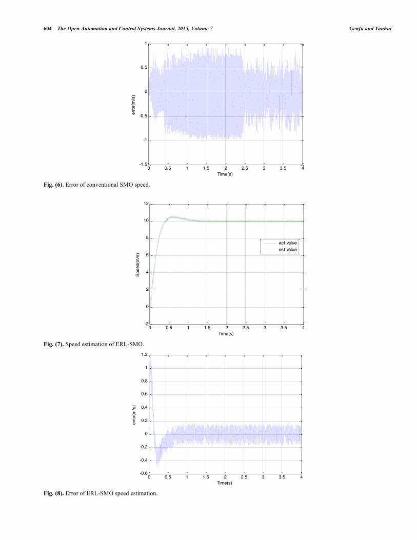
Fig. (7). Speed estimation of ERL-SMO.
Fig. (8). Error of ERL-SMO speed estimation.
0 0.5 1 1.5 2 2.5 3 3.5 4-1.5
-1
-0.5
0
0.5
1
Time(s)
error(m
/s)
0 0.5 1 1.5 2 2.5 3 3.5 4-2
0
2
4
6
8
10
12
Time(s)
Spee
d(m
/s)
act valueest value
0 0.5 1 1.5 2 2.5 3 3.5 4-0.6
-0.4
-0.2
0
0.2
0.4
0.6
0.8
1
1.2
Time(s)
error(m
/s)

An Exponential Reaching Law Sliding Mode Observer The Open Automation and Control Systems Journal, 2015, Volume 7 605
Fig. (9). Position estimation of ERL-SMO.
Fig. (10). Error of position estimation.
4. SIMULATIONS AND ANALYSIS OF RESULTS
In order to verify the effectiveness, the ERL-SMO is simulated in Matlab/Simulink. The PMSM parameters are shown in Table 1.
The vector control method is adopted, using a step func-tion as speed input. Because of the mutual coupling of d, q-axis variable, feed-forward decoupling control strategy is applied. Sensorless control system block diagram is shown in Fig. (4).
Figs. (5, 6) are the PMSM speed estimated value and the speed error of the conventional SMO. As can be seen, be-cause of the switch function, there is a big chattering.
Figs. (7, 8) are the PMSM speed estimated value and the speed error of the ERL-SMO. As can be seen, in the dynam-ic process, ERL-SMO can track actual speed value quickly. After entering the steady state, the estimated error is close to zero.
Figs. (9, 10) are the PMSM rotor position estimated value through the ERL-SMO and the estimation error of the rotor position. As can be seen, error of position estimation is small and the estimation of the rotor position is accurate.
CONCLUSION
This paper has proposed an ERL-SMO for a sensorless system for a PMSM. The stability of the new SMO has been proved with the use of a Lyapunov stability analysis. The chattering problem in the conventional SMO was resolved by using the exponential reaching law instead of the conven-tional sign function. A PLL was employed to reduce the es-timated error associated with low pass filter. The superiority of ERL-SMO has been confirmed through simulation. The ERL-SMO improves the reliability and accuracy of predic-tion of the rotor position, having significance in terms of the practical application and theory research.
0 0.5 1 1.5 2 2.5 3 3.5 40
1
2
3
4
5
6
7
Time(s)
Thet
a(ra
d)
act valueest value
0 0.5 1 1.5 2 2.5 3 3.5 4-8
-6
-4
-2
0
2
4
6
8
Time(s)
Error(rad)

606 The Open Automation and Control Systems Journal, 2015, Volume 7 Genfu and Yanhui
CONFLICT OF INTEREST
The authors confirm that this article content has no con-flict of interest.
ACKNOWLEDGEMENTS
This work was supported by Science and Technology Support Project of Jiangxi Province of China (No.2014-2BBE50057).
REFERENCES [1] A. Wang, and X. Jia, “A new exponential reaching law of sliding
mode control to improve performance of permanent magnet syn-chronous motor,” IEEE Trans. Magn., vol. 49, pp. 2409-2412, 2013.
[2] P. Pillay, and R. Krishnan, “Application characteristics of perma-nent magnet synchronous and brushless dc motor for servo drive,” IEEE Trans. Ind. Appl., vol. 27, pp. 986-996, 1991.
[3] F. Parasiliti, R. Petrella, and M. Tursini, “Sensorless speed control of a PM synchronous motor by sliding mode observer,” Proc. IEEE ISIE, vol. 3, pp. 1106-1111, 1997.
[4] P. Vaclavek, and P. Blaha, “Lyapunov function-based flux and speed observer for ac induction motor sensorless control and pa-rameters estimation,” IEEE Trans. Ind. Electron., vol. 53, pp. 138-145, 2006.
[5] S. Ichikawa, M. Tomita, S. Doki, and S. Okuma, “Sensorless con-trol of permanent magnet synchronous motors using online parame-ter identification based on system identification theory,” IEEE Trans. Ind. Electron., vol. 53, pp. 363-372, 2006.
[6] S. Chi, Z. Zhang, and L. Xu, “Sliding mode sensorless control of direct drive PM synchronous motors for washing machine applica-tions,” IEEE Trans. Ind. Appl., vol. 45, pp. 582-590, 2009.
[7] H. Kim, and J. Son, “A high-speed sliding-mode observer for the sensorless speed control of a PMSM,” IEEE Trans. Ind. Electron., vol. 58, pp. 4069-4077, 2011.
[8] Z. Qiao, and T. Shi, “New sliding-mode observer for position sen-sorless control of permanent-magnet synchronous motor,” IEEE Trans. Ind. Electron., vol. 60, pp. 710-719, 2013.
[9] H. Lee, and J. Lee, “Design of iterative sliding mode observer for sensorless PMSM control,” IEEE Trans. Control Syst. Technol., vol. 21, 2013.
[10] B. Thiago, and F. M. Vinicius, “Discrete-time sliding mode ob-server for sensorless vector control of permanent magnet synchro-nous machine,” IEEE Trans. Ind. Electron., vol. 61, pp. 1679-1691, 2014.
[11] Y. Feng, X. Yu, and F. Han, “High-order terminal sliding-mode observer for parameter estimation of a permanent magnet synchro-nous motor,” IEEE Trans. Ind. Electron., vol. 60, no. 10, pp. 1272-4280, 2013.
[12] S. Wang, and X. Li, “Computer-controlled variable structure sys-tems: The state of the art”. IEEE Trans. Ind. Informat., vol. 8, pp. 197-205, 2012.
[13] G. Foo, and M. F. Rahman, “Rotor position and speed estimation of avariable structure direct torque controlled IPM synchronous motor drive at very low speeds including standstill,” IEEE Trans. Ind. Electron., vol. 57, pp. 3715-3723, 2010.
[14] M. L. Corradini, G. Ippoliti, S. Longhi, and G. Orlando, “A quasi sliding mode approach for robust control and speed estimation of PM synchronous motors,” IEEE Trans. Ind. Electron., vol. 59, pp. 1096-1104, 2012.
[15] G. Tarchala, “Influence of the sign function approximation form on performance of the sliding-mode speed observer for induction mo-tor drive,” In: Proceeding of IEEE International Symponysim. Ind. Electron., 2011, pp. 1397-1402.
[16] G. L. Cascella, N. Salvatore, and L. Salvatore, “Adaptive sliding-mode observer for field oriented sensorless control of SPMSM,” Proc. IEEE Ind. Appl. Conf., vol. 2, pp. 1137-1143, 2003.
Received: September 16, 2014 Revised: December 23, 2014 Accepted: December 31, 2014
© Genfu and Yanhui; Licensee Bentham Open.
This is an open access article licensed under the terms of the Creative Commons Attribution Non-Commercial License (http://creativecommons.org/licenses/by-nc/4.0/) which permits unrestricted, non-commercial use, distribution and reproduction in any medium, provided the work is properly cited.


![[G73] PMSM Document](https://img.dokumen.tips/doc/110x75/5475c6b7b4af9f29698b4589/g73-pmsm-document.jpg)