Embed Size (px)
Citation preview

AN EXPERIMENTAL INVESTIGATION OF A
METER-SCALE FLAT-PLATE OSCILLATING HEAT PIPE
A Thesis
presented to
the Faculty of the Graduate School
at the University of Missouri-Columbia
In Partial Fulfillment
of the Requirements for the Degree
Master of Science
by
MICHAEL R. WILSON
Dr. Hongbin Ma, Thesis Supervisor
MAY 2016

The undersigned, appointed by the Dean of the Graduate School, have examined the thesis
entitled
AN EXPERIMENTAL INVESTIGATION OF A METER-SCALE FLAT-
PLATE OSCILLATING HEAT PIPE
presented by Michael R. Wilson,
a candidate for the degree of Master of Science,
and hereby certify, that in their opinion, it is worthy of acceptance.
_______________________________________________
Professor Hongbin Ma
_______________________________________________
Professor Robert Winholtz
_______________________________________________
Professor Stephen Montgomery-Smith

Dedication
To my parents, you did pretty well considering the ill-posed problem of having a child.

ii
Acknowledgments
To Dr. Hongbin Ma, he has shown me through example how to be an independent
professional while striving through collaboration. I cannot say enough about my friends
and colleagues from the thermal lab; Fritz Laun, Hanwen Lu, Tom Zhang, Wolfgang Black,
Eric Urad, Corey Wilson, Hamid Reza Seyf, Scott Thompson, Aaron Hathaway, Chris
Smoot, and Hai Wang. I must thank Marilyn Nevels and the MAE department for their
persistent support. I would also like to thank my most influential educators Ms. Penny
Kreul, Mrs. Cynthia Stica, Prof. Les Reid, Prof. Scott M. Thompson, and Prof. Gary L.
Solbrekken. None of this would have been possible without the abundant, endearing
support from Mason Bartlett, Blake Baumberger, Justin Johnson, Ryan Montgomery, and
Andrew Underwood. Only some of this would have been possible without the love and
support from Matt Wilson, Brian/Ron/Chris Roling, Katie/Chris Bakunas, Phillip Aron
McCart, Michael Rutz, Brett Brusda, Chris Vandiver and Spencer Gardner.

iii
Table of Contents
ACKNOWLEDGMENTS ............................................................................................... II
TABLE OF FIGURES ..................................................................................................... V
LIST OF TABLES ....................................................................................................... VIII
NOMENCLATURE ........................................................................................................ IX
ABSTRACT ..................................................................................................................... XI
1.0 INTRODUCTION................................................................................................. 1
1.1 Thermal Management of Electronics .............................................................................. 1
2.0 OSCILLATING HEAT PIPES ............................................................................ 3
2.1 Oscillating Heat Pipe Operation ...................................................................................... 3
3.0 DESIGNING OSCILLATING HEAT PIPES .................................................... 6
3.1 Working Fluid Selection ................................................................................................... 6
3.1.1 Working Fluid Temperature Range .............................................................................................. 6
3.1.2 (𝒅𝒑/𝒅𝑻)𝒔𝒂𝒕 ................................................................................................................................ 8
3.1.3 Thermal Stability .......................................................................................................................... 9
3.1.4 Latent Heat ................................................................................................................................. 10
3.1.5 Low Viscosity ............................................................................................................................ 11
3.1.6 Nanofluids .................................................................................................................................. 11
3.2 Channel Sizing ................................................................................................................ 13
3.3 Channel Configuration ................................................................................................... 18
3.4 Turn Number .................................................................................................................... 24

iv
3.5 Material Selection and Compatibility ............................................................................ 27
4.0 SEALING OSCILLATING HEAT PIPES ....................................................... 29
4.1 Pinch-Off Tube Selection ............................................................................................... 29
4.2 Copper .............................................................................................................................. 31
4.3 Nickel ................................................................................................................................ 31
4.4 Other Materials ................................................................................................................ 31
4.5 Pinch-off Tool Selection ................................................................................................. 32
4.6 Pinch-off Process............................................................................................................ 33
4.6.1 Preparing for Pinch-off ............................................................................................................... 33
4.6.2 The Pinch ................................................................................................................................... 33
5.0 OSCILLATING HEAT PIPES IN MICROGRAVITY .................................. 35
6.0 METER-SCALE OHP EXPERIMENT WITH KILOWATT-SCALE HEAT
INPUTS ............................................................................................................................ 41
6.1 Introduction ..................................................................................................................... 41
6.2 Prototype Design ............................................................................................................ 42
6.3 Charging Procedure........................................................................................................ 44
6.4 Experimental Setup......................................................................................................... 45
6.5 Results and Discussion ................................................................................................. 48
6.5.1 Uncertainty Analysis .................................................................................................................. 48
6.5.2 Thermal Performance ................................................................................................................. 49
6.5.3 Steady-State Oscillations ............................................................................................................ 51
7.0 CONCLUSION ................................................................................................... 56
8.0 REFERENCES .................................................................................................... 57

v
Table of Figures
Fig. 1. Timeline of the component heat flux increase [2]. ........................................................... 1
Fig. 2. Schematic of a typical OHP [6]. ........................................................................................ 4
Fig. 3. Pressure-enthalpy diagram of OHP cycle [7]. ................................................................. 4
Fig. 4. Saturation Pressure-Temperature curve for low temperature working fluids. ........... 8
Fig. 5. Minimum diameter as a function of temperature. ........................................................ 14
Fig. 6. Maximum diameters as a function of temperature. ...................................................... 14
Fig. 7. A proportional schematic of (a) square, (b) circular, and (c) triangular cross-sections
with the same hydraulic diameters [44]. .................................................................................... 17
Fig. 8. Schematics of the (a) Closed loop OHP and (b) open loop (OLOHP)
configurations. .............................................................................................................................. 18
Fig. 9. (a) Closed-loop T-OHP and an (b) open-loop T-OHP with air-cooled heat sink [51, 52].
19
Fig. 10. 3D or wrapped (a and b) 20-turn and (c) 10-turn tubular OHP [53]. ....................... 19
Fig. 11. (a) Conventional FP-OHP and (b) a FP-OHP thermal spreader (i.e. center
heated). .......................................................................................................................................... 19
Fig. 12. (a) Photograph of the 3D FP-OHP and (b) channel configuration with staggered
channel profile [54]. ..................................................................................................................... 20
Fig. 13. Top and bottom channel configuration of a 3D FP-OHP with a parallel channel
profile. 21
Fig. 14. Interconnected layered FP-OHP. .................................................................................. 21
Fig. 15. Layered FP-OHP with a cross-sectional view showing how the two independent OHP
channel arrays are connected [55]. ............................................................................................. 21
Fig. 16. (a) Top view and (b) side view of a 3D T-OHP with an uneven turn count [56]. ...... 22

vi
Fig. 17. (a) Uniform (2 x 2 mm2) channeled FP-OHP and (b) a non-uniform (1 x 2 mm2 and 2
x 2 mm2) channeled FP-OHP [57]. ............................................................................................. 22
Fig. 18. Schematic of (a) an T-OHP with check valves and (b) a ball check valve [59]. ........ 23
Fig. 19. A FP-OHP with Tesla valves [60].................................................................................. 23
Fig. 20. Relative thermal performance of (a) the 16 and 23 turn OHPs and (b) OHPs with less
than 16 turns [63]. ........................................................................................................................ 25
Fig. 21. Effect from varying number of turns [63]. ................................................................... 26
Fig. 22. Crimped copper tubing showing (a) proper pinch-off and (b) premature separation
[75]. 30
Fig. 23. Photographs of (a) a scissor style, 45 deg angled jaw handset and (b) a C-style with
parallel action jaw handset [75]. ................................................................................................. 32
Fig. 24. Axis system for parabolic aircraft [76]. ........................................................................ 35
Fig. 25. Parabolic profile of flight tests [77]. .............................................................................. 36
Fig. 26. (a) Drawing of the 3D FP-OHP prototype and (b) close-up of the machined
surface. .......................................................................................................................................... 43
Fig. 27. OHP charging setup for backfill method. .................................................................... 45
Fig. 28. Photograph of the experimental setup excluding heaters and insulation. ................. 46
Fig. 29. Schematic of experimental setup. .................................................................................. 47
Fig. 30. Heating and cooling configuration for the 3D FP-OHP. ............................................. 47
Fig. 31. Top view of the OHP showing the thermocouple layout. ............................................ 48
Fig. 32. Resistance as a function of power input with the effect of cooling bath
temperature. ................................................................................................................................. 50
Fig. 33. Nondimensionalized temperature profiles along the length for various power inputs
and cooling bath temperature of 10°C. ...................................................................................... 51
Fig. 34. Steady-state oscillations in the evaporator for a power input of 100 W and a cooling
bath temperature of 40°C for (a) side A and (b) side B. ........................................................... 52

vii
Fig. 35. Steady-state oscillations in the evaporator during a power input of 3.75 kW and a
bath temperature of 40°C for (a) side A and (b) side B. ........................................................... 53
Fig. 36. Average peak-to-peak amplitude of the evaporator and condenser for increasing
power input and varying condenser temperature. .................................................................... 54

viii
List of Tables
Table 1. Useful ranges for various working fluids [12]............................................................... 6
Table 2. Mean time study results [62]. ....................................................................................... 24
Table 3. Compatibility of structure materials and low-temperature working fluids. ........... 28
Table 4. Approximate tube deformation due to pinch-off........................................................ 31
ix
Nomenclature
A Area [m2]
Bo Bond number [--]
D Diameter [m]
g Gravity [m/s2]
Ga Garimella number [--]
ℎ𝑙𝑣 Latent heat of vaporization [kJ/kg]
h Enthalpy [kJ/kg]
k Thermal conductivity [W/m-K]
L Length [m]
P Perimeter [m]
p Pressure [Pa]
Q Heat rate [W]
Q* Heat rate per turn [W]
Re Reynolds number [--]
T Temperature [K]
t Thickness [m]
U Velocity [m/s]
w Width [m]
We Weber number [--]
Greek
𝜇 Dynamic viscosity [Pa·s]
𝜌 Density [kg/m3]

x
𝜎 Surface tension [N/m]
Subscripts
a Adiabatic
avg Average
c Condenser
e Evaporator
eff Effective
H Hydraulic
l Liquid
max Maximum
min Minimum
sat Saturation
th,OHP Thermal Resistance of the OHP
t Turns
v Vapor
w Wall
x Cross-section

xi
Abstract
Ever-increasing demand for power in modern electronics presents challenge in
thermal management. This paper shows the oscillating heat pipe (OHP) is considered a
preferred solution for high heat application due to its heat transfer capability. The
experimental investigation of a meter-scale (i.e., 0.915 m) interconnected layered flat plate
oscillating heat pipe (FP-OHP) was carried out to determine the heat transport capability.
The prototype was carefully designed to have 14 turns within a cross section of 31.75 x
6.35 mm2 by embedding micro channels with a hydraulic diameter of 1.36 mm. The results
show that the FP-OHP was able to transport a maximum power of 4.5 kW with a heat flux
of 2.2 kW/cm2. As the power becomes high, the oscillating motion becomes stronger
resulting in a higher heat transport capability. When the power increases, the operating
temperature increases which decreases the viscosity resulting in a decrease of pressure
drop. At the same time, when power increases, the driving force increases, which directly
enhances heat transfer. In addition, the FP-OHP is able to successively produce oscillating
motion over a very large power range for this meter long OHP. It has been shown that FP-
OHPs can achieve high performance over long transport lengths with kilowatt heat inputs.

1
1.0 Introduction
1.1 Thermal Management of Electronics
The unprecedented growth of heat fluxes ascended from 0.5 W/cm2 in the 1980’s
to more than 15 W/cm2 by 2000 (Fig. 1). Future heat-rejection capabilities are expected to
be measured in the 1000’s of W/cm2 for space applications, such as GaN power amplifiers
[1]. According to Ebadian et al. [1], heat fluxes can be categorized into three regions:
High heat flux (HHF): 102 – 103 W/cm2
Ultra-high heat flux (UHF): 103 – 104 W/cm2
Extreme heat flux (EHF): >104 W/cm2.
Most of the next generation electronics are in the HHF range with some reaching
the UHF range. As cooling technologies lag further behind, the aggregate thermal problem
becomes worse due to the increase contact resistance, which stems from more thermal
expansion at elevated temperatures.
Fig. 1. Timeline of the component heat flux increase [2].

2
Currently, non-passive thermal systems available to deal with these large heat
fluxes add mass, occupy valuable space, consume power, and can drastically increase the
cost of manufacturing the final product. Current passive thermal technologies cannot
efficiently remove ultra-high heat fluxes regardless of cost. However, a type of passive
thermal system, the oscillating heat pipe (OHP), might have the potential to remove high
power with high heat flux at a low cost.

3
2.0 Oscillating Heat Pipes
2.1 Oscillating Heat Pipe Operation
OHPs are a two-phase heat transfer device partially filled with a working fluid that
uses the thermal energy added on the heat pipe to generate oscillatory motions, which can
efficiently transfer heat between the evaproator and condenser [3, 4]. An OHP is a simply
formed, wickless heat pipe cosnisting of capillary tubes (Fig. 2). The primary OHP driving
force is the result of the difference in working fluid saturation pressure that exists in the
evaporator and in the condenser. This pressure difference between the evaporator (hot end)
and the condenser (cold end) drives the two-phase fluid motion. So long as the evaporator
is kept sufficiently hot, and the condenser sufficiently cold, the driving pressure exists
which will be one necessary condition to generate the self-sustaining oscillatory motion.
When an OHP is constructed, channels are evacuated and then partially filled with
working fluid, resulting in a mixture of liquid slugs and vapor plugs. An isentropic
thermodynamic cycle for an operating OHP is given Fig. 3, where the temperature and
vapor quality are known at the outlets of the evaporator (i.e., point B) and condenser (i.e.,
point E) sections [5]. Due to bubble expansion, the pressure is increased from the inlet to
the outlet of the evaporator section (i.e., A to B in Fig. 3). As the oscillating flow moves
from the evaporator to the condenser through the adiabatic section, the pressure decreases
isenthalpically (i.e., B to D in Fig. 3). Conversely, due to condensation (i.e., vapor bubble
contraction), the mixture will experience a drop in vapor pressure as it passes through the
cooling section and rejects heat (i.e., D to E in Fig. 3). Finally, the mixture undergoes an
isenthalpic pressure drop as it returns from the cooling section to the heating section
through the adiabatic section (i.e., E to A in Fig. 3). The assumptions made to produce this
thermodynamic model are unrealistic due to the chaotic nature of an OHP. For example,

4
the state of the evaporator and condenser outlets are extemely difficult to retrieve as there
are multiple outlets for an OHP device and flow is chaotic in nature.
Fig. 2. Schematic of an OHP [6]. Fig. 3. Pressure-enthalpy diagram of OHP cycle [7].
OHPs typically exist as a single loop serpentine tubular design or an engraved
channel on a flat plate such as a flat-plate OHP (FP-OHP) that is evacuated, charged, and
sealed. Compared with the conventional heat pipe (CHP), OHPs differ greatly in the
following ways:
1. CHPs are highly gravity dependent, while OHPs are not [8, 9];
2. OHPs have a high potential to handle a much higher heat flux [10];
3. OHPs do not need an intricate internal wick structure to promote capillary action to
transport liquid back to the condenser, greatly reducing the manufacturing cost
[11];
4. OHPs can transpor heat in a long distance;
5. Prior to startup, the OHP will act as an insulator due to its poor performance while
the slug and plugs are stagnant. As heat input increases, oscillating motion will
begin (i.e., startup) and become stronger thereby improving heat transport

5
capability. Exploiting these features can allow a simple OHP to act as a sort of
switch and/or variable conductance device.

6
3.0 Designing Oscillating Heat Pipes
3.1 Working Fluid Selection
Selecting working fluid(s) is very important because of the effects it has on heat
transfer performance, operating temperature, geometry (Sections 3.2 - 3.4) and material
compatibility (Section 3.5). Careful selection of working fluid in coordination with the
given application (i.e. sizes, heat inputs) can have direct impact on the OHP performance.
The following sections will detail the heritage of fluids in OHPs, thermal stability, and the
effects of several thermophysical properties.
3.1.1 Working Fluid Temperature Range
A list of working fluids for CHPs is given in Table 1 where the useful range was determined
by Faghri [12]. Because the OHP utilizes the phase-change heat transfer to generate the
oscillating motion, which is similar to CHP, these useful ranges can be applied to OHPs as
well. Furthermore, the range is mainly determined by the critical and melting temperatures,
thus the useful range of OHPs are similar to CHPs.
Cryogenic OHPs are a relatively new addition to the OHP field of study. Han et al. [13]
studied the cooling rate of a liquid nitrogen (LN2) charged OHP for cell vitrification
cryopreservation. Jiao et al. [14] investigated a LN2 filled OHP and found a decrease in
thermal resistance with increasing power input. Natsume et al. [15-17] investigated the
use of tubular and flat-plate OHPs filled with hydrogen, neon and nitrogen to cool
superconducting magnets. The range of operation for hydrogen, neon, and nitrogen was
17-27 K, 26-34 K, and 67-91 K, respectively. These ranges are very similar to the useful
ranges given for CHPs in Table 1.

7
Table 1. Useful ranges for various working fluids [12].
Working
Fluid
Melting
Point [K]
Critical
Point [K]
Useful
Range [K]
Working
Fluid
Melting
Point [K]
Critical
Point [K]
Useful
Range [K]
Helium 0.95 5.195 2-4 R-11 162.7 471.1 233-393
Hydrogen 13.96 33.14 14-31 Pentane 143.5 469.7 253-393
Neon 24.56 44.49 27-37 Freon 113 236.9 487.2 263-373
Nitrogen 63.15 126.2 70-103 Acetone 178.2 508.2 273-393
Argon 83.81 150.7 84-116 Methanol 175.6 512.6 283-403
Oxygen 54.36 154.4 73-119 FlutecPP2 236.1 759.1 283-433
Methane 90.69 190.6 91-150 Ethanol 159.0 515.0 273-403
Krypton 115.8 209.5 116-160 Heptane 182.6 540.1 273-423
Ethane 90.35 305.3 150-240 Water 273.2 647.1 303-550
R-22 115.7 369.3 193-297 Toluene 178.0 591.7 323-473
Ammonia 195.5 405.4 213-373 FlutecPP9 203.1 859.8 273-498
R-12 116.1 385.1 203-313 Naphthalene 353.4 750.0 408-623
R-134a 169.9 374.2 208-313 Dowtherm A 285.1 770.0 423-668
R-21 200.0 451.5 233-360
Low-temperature working fluids have received the majority of the attention from
the OHP community as a direct result from the electronics-cooling bottleneck. The
following working fluids have been tested: water, ethanol, acetone, methanol, isopropyl
alcohol, ammonia, R114, R123, R134a, R141b, R142b, FC-72, FC-75, HFE-7000, and
HFE-7100 [7, 18, 19]. In this temperature range, new designer and binary fluids will
continue to expand capabilities [20-22].
The wide range of working fluids available to OHPs makes them capable for vast
application. The temperature ranges, or operational ranges, of working fluids for OHPs
can only be used as basic selection criteria to make sure pressures will not be too great and
critical fluid conditions will not be met during operation. Thermally, the OHP operation
depends more on heat input and flux than the temperature, but condenser and evaporator
temperatures do play a role.

8
3.1.2 (𝒅𝒑/𝒅𝑻)𝒔𝒂𝒕
The partial derivative of the working fluid’s pressure-temperature saturation curve
(𝑑𝑝/𝑑𝑇)𝑠𝑎𝑡 has been discussed throughout OHP research [7, 23]. The pressure-
temperature curve shown in Fig. 4 displays this important characteristic of OHP
performance for a variety of working fluids. With a higher partial derivative of (𝑑𝑝/𝑑𝑇)𝑠𝑎𝑡
over the operating range, OHP performance is increased due to the larger pressure
differences between the evaporator and condenser, which is developed by the rapid rate at
which bubbles expand and coalesce [7]. Careful selection in regards to this characteristic
can allow an OHP to act as a thermal switch of sorts where the static frictional forces will
dominate until the operating temperature reaches a steeper portion of the curve, inducing
oscillating motion.
Fig. 4. Saturation Pressure-Temperature curve for low temperature working fluids.
A working fluid should be selected that utilizes a larger derivative on the pressure-
temperature saturation curve which produces larger pressure differences with changes in

9
temperature allowing for increased OHP performance. Careful selection with respect to
the operating requirements can extend the range of OHP operation. Furthermore, complex
OHPs consisting of multiple, carefully selected working fluids can extend the operating
range even further.
3.1.3 Thermal Stability
Thermal stability of a working fluid must be taken into consideration as it can have
adverse effects on OHP operation. Organic fluids have been known to reach temperatures
beyond their respective range of operation and break down into various compounds.
Organic fluids are any fluids whose molecule contains carbon. Acetone, alcohols, and the
majority of refrigerants are organic fluids. Heat pipe performance would diminish if these
organic compounds were to break down due to the non-condensable gases (NCGs) that
would be created within the heat pipe [24]. Heat pipes have used all of these fluids.
However, it is necessary to test at the application’s ceiling temperature within all
perspective tubing/housing materials in order to ensure no degradation [25]. If a fluid is
brought to a temperature close enough to its critical limit, the fluid will break down into
NCGs, and the original composition of the fluid will not be able to be recovered even after
the temperature is lowered below this critical point. If this cyclic rise and fall of the
operating temperature interferes with these “break-down” limits, a chemical creep
phenomenon occurs and the performance of the OHP will degrade over time as less and
less of the actual refrigerant becomes present inside of the OHP.
Thermal stability of the working fluid is critical for proper selection. The maximum
temperature of the OHP application must be evaluated to ensure the working fluid’s

10
thermal stability. If a working fluid does not preserve its thermal stability, NCGs will be
created that perpetually degrade thermal performance until the OHP is rendered inoperable.
3.1.4 Latent Heat
The amount of latent heat a fluid has alters startup of the oscillating motion as well
as the overall thermal performance. If a fluid has a low latent heat, the rate of phase-change
will be higher at any given temperature and result in higher vapor pressure, which will
readily generate oscillating motions and lead to higher performance [7, 26]. Unlike CHPs,
OHPs transfer the majority of heat through sensible heat transfer [27-30], so the higher
flow rate driven by more vapor creation, from having a lower latent heat, is more beneficial.
By directly comparing multiple working fluids, Han et al. [31] determined that high
latent heat was favorable at high power levels and dryout was more likely to occur for
OHPs with low latent heat and low fill ratios. Qu and Ma [32] showed that the superheat
to grow a bubble in an OHP depends on the latent heat, i.e.,
𝑇𝑤 − 𝑇𝑣 =𝑅𝑇𝑤𝑇𝑣
ℎ𝑙𝑣ln [1 +
2𝜎
𝑝𝑣(
1
𝑟𝑐−
1
𝑟𝑔𝑙𝑜𝑏𝑒)] (1)
where 𝑇𝑤 is the wall temperature, 𝑇𝑣 is the vapor saturation temperature, 𝑅 is the gas
constant, ℎ𝑙𝑣 is the latent heat of vaporization, 𝜎 is surface tension, 𝑝𝑣 is the vapor pressure,
𝑟𝑐 is the cavity radius, 𝑟𝑔𝑙𝑜𝑏𝑒 is the bubble radius of the large bubble, 𝜌𝑣 and 𝜌𝑙 are the
vapor and liquid densities. Once the required superheat (𝑇𝑤 − 𝑇𝑣) is achieved in Eq. (1),
boiling will ensue creating vapor plugs. Water needs much higher superheat for the startup
of an OHP than methanol, ethanol and acetone. It means that the OHP charged with water
needs a heat flux much higher than the one with methanol, ethanol or acetone for an OHP
to start up the oscillating motion.

11
Latent heat of a working fluid should be used to tailor the performance target of an
OHP. Startup can be produced early by utilizing a low latent heat while high performance
at high heat input can be obtained by a high latent heat working fluid.
3.1.5 Low Viscosity
For OHP operation, a working fluid with low viscosity will provide increased
performance. Viscosity dampens the oscillatory flow by increasing pressure drop along the
channel wall due to the increased shear stress [6, 7]. Low viscosities reduce the required
heat input to maintain efficient OHP operation [7, 26]. Han et al. [31] compared water,
methanol, ethanol, and acetone as working fluids in a 2 mm T-OHP and found that dynamic
viscosity might be another important term for startup. Working fluids with lower viscosity
should be selected to assist startup. More generally, lower viscosity working fluids should
always be selected to decrease the dampening effect of friction throughout the system.
3.1.6 Nanofluids
Ma et al. [33] investigated a copper T-OHP with 12 turns that was charged with
water consisting of 1.0 vol% diamond particles with 5-50 nm diameters. The addition of
nanofluid reduced the temperature drop across the OHP from 42°C to 25°C at the heat
input of 100 W. Cheng et al. [34] tested two staggered-profile OHPs with nanofluids: (1)
a 10-turn and 1 x 1 mm2 channels filled with 0.1 vol% diamond/acetone and (2) an 8-turn
and 1.7 x 1.175 mm2 channels filled with 1.0 vol% diamond/water and 0.0003 vol%
gold/water. Both showed an extended range of operation, with respect to input power, and
better performance across the entire operational range. Startup of the diamond/acetone
nanofluid OHPs was at a higher heat input than the pure acetone OHP of the same
dimensions. Qu et al. [35] experimentally investigated an OHP filled with water and Al2O3

12
nanoparticles with diameters of 56 nm. It was discovered that the nanoparticles were
settling on the wall of the OHP changing the surface condition, thereby enhancing thermal
performance. Ji et al. [36] tested the effect of the particle size on OHP performance by
using four particle size diameters of 50 nm, 80nm, 2.2 µm, and 20 µm. Each of the four
particle sizes increased performance with the 80 nm particle displaying the highest
performance. Li et al. [37] performed a visualization study of OHP two-phase flow using
SiO2 particles with a diameter of 15 nm in water. The nanofluid allowed the 3-turn OHP
to reach slug and annular flow regimes while the water-only charged OHP never left the
column flow regime. Riehl and dos Santos [38] compared a water-copper nanofluid to
pure water. The nanofluid had copper particles with 25 nm diameter, made up 5 mass%,
and increased the thermal conductance in all orientations at power levels of 30, 40, and 50
W. The authors stated, “At low heat loads, the copper nanoparticles were influencing the
film evaporation as they increase the water thermal conductivity. At higher heat loads, the
nanoparticles acting as nucleation sites improve the nucleation boiling resulting on the
appearing of the pulsating flow.” Zhao et al. [39] modeled the nanofluid effect on thin film
evaporation and found that nanoparticles suspended in Brownian motion, which should be
present in oscillatory motion, increase liquid film thickness and thin film evaporation.
Since Ma et al. [33] were the first to charge an OHP with a nanofluid, incorporating
nanofluids into OHPs has been shown to have positive effects on performance. The
increase in performance has been attributed to the nanofluid enhancing the surface
condition, increasing convection heat transfer, adding nucleation sites throughout the fluid,
and increasing thin film evaporation. The longevity of nanofluid effectiveness in OHPs

13
has yet to be examined at this point; implementation into real-world application would
require rigorous testing.
3.2 Channel Sizing
Channel diameter is dictated by the working fluid properties, which can be used to
define an OHP sizing criteria (i.e. minimum and maximum diameters). Typically, OHP
channels have been sized using a dimensionless group called the Bond number (Bo), i.e.
Bo =g(ρl−ρv)D2
σ (2)
which is a ratio of the working fluid’s buoyancy force to the surface tension force of the
vapor bubble generated inside the channel. According to [7, 40] the upper limit of the
Bond number is between 3.39 and 4 and the lower limit is between 0.36 and 0.49 according
to [41, 42]. Using conservative Bond numbers of 0.49 and 3.39 and rearranging Eq. (2),
the recommended minimum (𝐷𝑚𝑖𝑛) and maximum (𝐷𝑚𝑎𝑥) channel diameters are given by
𝐷𝑚𝑖𝑛 = 0.7√𝜎
𝑔(𝜌𝑙−𝜌𝑣) 𝐷𝑚𝑎𝑥 = 1.84√
𝜎
𝑔(𝜌𝑙−𝜌𝑣) (3)
respectively, where 𝜎 is surface tension, g is gravity, 𝜌𝑙 is the density of the liquid, and 𝜌𝑣
is the density of the vapor. The diameter of the tubing needs to be smaller than the actual
vapor bubble size in order to achieve effective slug-plug flow. If a diameter below 𝐷𝑚𝑖𝑛
is used, the friction forces will dominate, causing the OHP not to startup due to high
frictional force to be overcome. Conversely, if the diameter is above 𝐷𝑚𝑎𝑥, then capillary
forces will not be great enough to form the vapor bubbles and a train of liquid plugs and
vapor bubbles. As shown in Figs. 5 and 6, 𝐷𝑚𝑖𝑛 and 𝐷𝑚𝑎𝑥 depend on working fluid and
temperature. As temperature increases, surface tension decreases proportionally more than
the difference of the liquid and vapor densities, which gives smaller recommended
minimum and maximum diameters with increasing temperature.
14
Fig. 5. Minimum diameter as a function of temperature.
Fig. 6. Maximum diameters as a function of temperature.
Lin et al. [43] studied water-filled “mini” OHPs with inner diameters of 0.4 mm,
0.8 mm, 1.3 mm, and 1.8 mm and total lengths (i.e. 𝐿𝑒 + 𝐿𝑎 + 𝐿𝑐) of 100 mm, 150 mm,
and 200 mm. Results show that increasing the inner diameter or decreasing the total length
showed improvement in performance.
Cheng et al. [34] tested two OHPs with very similar overall dimensions with two
types of cross-sections – staggered and parallel. The parallel profile had 16 turns of 0.762

15
x 0.762 mm2 channels and the staggered only had 10 turns of 1 x 1 mm2 channels. At 140
W, the minimum thermal resistance was achieved by the parallel and staggered profiles at
values of 0.268 K/W and 0.174 K/W, respectively. Therefore, maximizing the number of
turns did not increase OHP performance.
Yang et al. [44] compared two ethanol charged aluminum FP-OHPs with an overall
volume of 180 x 120 x 30 mm3 – one with 40 turns and 2 x 2 mm2 square channels and the
other with 66 turns and 1 x 1 mm2 square channels. In the horizontal configuration at an
average evaporator temperature of 110°C, the larger 2 x 2 mm2 channels allowed for 390
W to be transferred while the 1 x 1 mm2 channels could only transfer 200 W. For ethanol,
the minimum and maximum recommended diameters are 1.16 mm and 3.05 mm,
respectively, at 110°C.
Anuchitchanchai et al. [45] investigated 27 copper T-OHPs with inner diameters of
0.66 mm, 1.06 mm, and 2.03 mm, with 5, 10, and 15 turns, and evaporator lengths of 50
mm, 100 mm, and 150 mm. The working fluids were HP62 and MP39, both of which are
refrigerant blends. The useful data was presented in terms of aspect ratio (length of
evaporator over diameter) which showed the critical heat flux decreasing as aspect ratio
increased. The data collected in order to determine a trend concerning Bond number were
inconclusive.
Katpradit et al. [46] studied two Pyrex glass, 10-turn OLOHPs with diameters of 1
mm and 2 mm and equal evaporator/adiabatic/condenser lengths of 50 mm and 150 mm.
The OHPs were filled with R123 to 50% by volume. All tests were performed in vertical,
evaporator-down configuration (i.e., favorable) and only consisted of two Bond numbers
and two aspect ratios (𝐿𝑒/𝐷). As Bond number increased the internal flow pattern changed

16
from annular to churn flow, increasing the film thickness and increasing the critical heat
flux (i.e., dryout). As aspect ratio increased, the flow pattern changed from churn flow to
annular flow, causing flooding at the evaporator entrance, which led to dryout. The results
of this experiment would have been more beneficial if performed in the horizontal
orientation because the vertical, favorable orientation tends to drive fluid back to the
evaporator. Consequently, the results from the Bond number study are biased because
gravity has a greater effect when the diameter is larger due to the decrease in flow resistance
or friction. This is substantial because all operational temperatures were greater than 20°C,
where 𝐷𝑚𝑎𝑥 for R123 is 1.92 mm, which is already smaller than the 2 mm diameter.
Yang et al. [47] tested 32-turn OHPs with microchannel-sized channels (0.5 x 0.25
mm2) filled with methanol and water. The water filled OHPs never produced oscillating
motion and the methanol OHP only did while in the vertical orientation, although the power
level did not exceed 19 W.
The shape of the channel should also be considered during OHP design. The
diameter for non-circular channels is calculated using hydraulic diameter (𝐷𝐻), given by
𝐷𝐻 =4𝐴𝑥
𝑃 (4)
where 𝐴𝑥 is the cross-sectional diameter and 𝑃 is the wetted perimeter. Comparing square
and circular channels, the volume per unit length for square channels is (4/π) times greater
than circular channels. At low filling ratios, the likelihood of liquid plug formation is much
higher in circular channels relative to non-circular channels. Figure 7 shows the
normalized comparison of different channel geometries with the same hydraulic diameters
and the fluid distribution at low filling ratios of 22, 28, and 39.5% for the square, circle,
and triangle, respectively. Perturbations at the interfaces will have varying affects

17
depending on geometry, which affects the flooding/bridging phenomena and Kelvin-
Helmholtz type instabilities [44].
Fig. 7. A proportional schematic of (a) square, (b) circular, and (c) triangular cross-
sections with the same hydraulic diameters [44].
Channel size is mainly dictated by the geometric requirements of a given
application. If the application is not restricting geometry, the size or thickness of the OHP
will be dictated by the necessary diameter for the environment. That is, whether or not the
OHP is in a favorable orientation, microgravity, or somewhere in between will be a huge
factor in determining the channel size. Section 0 discusses the state of the OHP with
respect to microgravity, which also deals with the channel sizing and prediction using
terrestrial experiments. Ultimately, channel size has a relatively (i.e., to capillary sizes)
wide range of possible diameters, but there are a wide range of thermal performances
resulting from this selection.

18
3.3 Channel Configuration
Extensive research of the OHP has led to a number of variations between the two
basic configurations: the closed loop OHP (CLOHP) and open loop OHP (OLOHP), shown
in Fig. 8. OLOHPs are much easier to manufacture and integrate simply because there is
no return loop needed to close the loop, although CLOHPs have been shown to outperform
OLOHPs because of the return loop [48-50]. The circulation motion can enhance
performance but the OLOHP will not allow this to occur.
Fig. 8. Schematics of the (a) Closed loop OHP and (b) open loop (OLOHP)
configurations.
Classic tubular OHPs (T-OHPs) are shown in Fig. 9. The wrapped or 3D T-OHP
was created to increase the number of turns in a smaller footprint (Fig. 10). However, the
out-of-plane turns have not been directly studied in order to test the effect of gravity.
Figure 11a shows the classic FP-OHP design while Fig. 11b shows how a FP-OHP can be
used as a thermal spreader. Note that Figs. 11a and 11b are displaying the internal design
without a top plate (i.e., prior to brazing), which is typically brazed on after milling the
channels.

19
Fig. 9. (a) Closed-loop T-OHP and an (b) open-loop T-OHP with air-cooled heat sink
[51, 52].
Fig. 10. 3D or wrapped (a and b) 20-turn and (c) 10-turn tubular OHP [53].
Fig. 11. (a) Conventional FP-OHP and (b) a FP-OHP thermal spreader (i.e. center
heated).

20
FP-OHPs can also have channels engraved on both sides and connected through the
thickness of the plate, coined as 3D FP-OHPs by Thompson et al. [54]. Figure 12 shows a
staggered profile design and Fig. 13 displays the parallel profile design. This type of 3D
FP-OHP interconnects channels in a way such that flow must take place from top to bottom
and vice versa unlike the experimental OHP studied in this thesis shown in Fig. 14. These
channel-to-channel connections do not force the fluid from top to bottom, so this is better
described as an “interconnected layered OHP”. If in fact thermal resistance was increased
through the thickness of the OHP, this configuration still may have its advantages during
the charging process (i.e. a single charging port versus multiple). Furthermore, a layered
OHP is one that consists of two or more OHP channel arrays that are independent from one
another in a single piece. Layered OHPs allow for the use of multiple working fluids within
a single device (Fig. 15).
Fig. 12. (a) Photograph of the 3D FP-OHP and (b) channel configuration with staggered
channel profile [54].

21
Fig. 13. Top and bottom channel configuration of a 3D FP-OHP with a parallel channel
profile.
Fig. 14. Interconnected layered FP-OHP.
Fig. 15. Layered FP-OHP with a cross-sectional view showing how the two independent
OHP channel arrays are connected [55].

22
Additional augmentations have been made to the basic flat plate and tubular
designs. Hathaway et al. [56] made a 3D T-OHP with an uneven turns, which consisted of
14 turns in both the evaporator and condenser and 6 additional half turns only in the
evaporator (Fig. 16). This design allows a higher percentage of the working fluid to be
maintained within the evaporator thus creating a more gravity-independent OHP [19].
Chien et al. [57] showed that an OHP with a non-uniform channel array could work in the
horizontal orientation while a similar uniform channel array could not operate (Fig. 17).
Fig. 16. (a) Top view and (b) side view of a 3D T-OHP with an uneven turn count [56].
Fig. 17. (a) Uniform (2 x 2 mm2) channeled FP-OHP and (b) a non-uniform (1 x 2 mm2
and 2 x 2 mm2) channeled FP-OHP [57].

23
Check valves have been added to the OHP since the inventor, Akachi [58],
suggested they be utilized. Since check valves can promote unidirectional flow (i.e.
circulation flow in an OHP), they seem to be an obvious addition as long as they can be
integrated. Conventionally, ball check valves have been used with OHPs for their
integration simplicity (Fig. 18); however, there remains a pressure drop even when the flow
is in the promoted direction. Tesla valves, albeit not as well as a ball check valve, promote
unidirectional flow without as much pressure drop through the main channel (Fig. 19).
Fig. 18. Schematic of (a) an T-OHP with check valves and (b) a ball check valve [59].
Fig. 19. A FP-OHP with Tesla valves [60].
Overall, the simple, yet highly augmentable OHP serves to fit innumerable
applications ranging from chip spreaders up to meter-scale length thermal issues (i.e.,
satellite cooling, solar water heaters). Intricate features, such as components that promote
circulation flow, can be added or removed from OHP designs to improve performance or

24
achieve a certain form factor or mass. Certain manufacturing methods can limit
configuration possibilities, although new methods, such as additive manufacturing, can
allow channel configurations to become more complex and compact.
3.4 Turn Number
Generally, the axiom of the OHP design is increasing the number of turns improves
heat transfer performance and negates the force of gravity [10, 18]. Adding turns creates
more locations for heating and cooling while adding more locations for instabilities, which
may be a reason for sustained oscillating motion. Park and Ma [61] studied circular pipe
with six distinct heating, cooling, and adiabatic sections (i.e. an OHP with no turns) and it
was shown that oscillations were very irregular. Melkikh and Dolgirev [62] investigated
the “mean time” of OHP operation (i.e. how long is oscillatory motion sustained) as a
function of turn-number. Table 2 shows the results from the testing that was done in the
unfavorable configuration (i.e. condenser down). Operation ceased once the oscillatory
operation was unable to replenish the evaporator with liquid because vapor creation, the
driving force, was eliminated (i.e. vapor lock). This experiment gives a clear indication of
the perturbation effects developed by adding turns.
Table 2. Mean time study results [62].
Turn No. 5 10 15 20
Time (min) 0 10 33 >180
Charoensawan et al. [9] carried out a thorough parametric study including effects
from turn-number (5, 7, 11, 16, and 23), internal diameter (1 mm and 2 mm), orientation
(0° to +90°), and working fluid (ethanol, R123, and water). Figure 20 shows the effects of
turn-number on thermal performance as a function of orientation. The turn-number 16 was

25
chosen as the “critical number” because the effect of gravity showed less impact on
maximum heat input. However, in the horizontal configuration, many of the OHPs with
16 and 23 turns displayed less than 60% of their maximum heat transfer. It is also
interesting to point out that most of the maximum heat transfer rates do not occur at 90°
implying the gravitational force can dampen oscillating motion when directly aligned with
the gravity vector.
Fig. 20. Relative thermal performance of (a) the 16 and 23 turn OHPs and (b) OHPs with
less than 16 turns [63].

26
Charoensawan and Terdtoon [63] showed (in Fig. 21) the effect of the number of
turns (5, 11, 16, and 26) on a T-OHP. It was shown that no oscillating motion was observed
in OHPs with five turns, and thermal resistance decreased as number of turns increased.
For startup, increasing evaporator temperature and tube diameter (1 mm, 1.5mm, and 2
mm) showed a lower number of required turns.
Fig. 21. Effect from varying number of turns [63].
Borgmeyer et al. [53] studied two 3D T-OHPs and showed that ∆𝑇 decreased with
increasing input power for the OHP with 20 turns, although the 10-turn OHP showed an
increase in ∆𝑇 with increasing input power. The performance displayed by the 20-turn
device is the desired OHP operation – where ∆𝑇 decreases as power input increases. This
performance characteristic makes OHPs highly attractive for application.
Cheng et al. [34] tested two water-filled flat-plate oscillating heat pipes (FP-OHPs)
with only 8 turns. The OHP with 1.7 x 1.175 mm2 channels displayed gravity
independence with heat inputs higher than 225 W. The other OHP with 1.175 x 1.175 mm2
channels was never gravity independent with a condenser temperature of 20°C, but was
almost completely orientation independent when the condenser temperature was at 60°C.

27
Cheng et al. [34] also tested two FP-OHPs with a footprint of 130.2 x 38.1 mm2 and two
types of cross-sections – staggered and parallel. The parallel profile had 16 turns of 0.762
x 0.762 mm2 channels and the staggered only had 10 turns of 1 x 1 mm2 channels. At 140
W, the minimum thermal resistance achieved by the parallel and staggered profiles was
0.268 K/W and 0.174 K/W, respectively. It should be noted that both of these channel
diameters violate 𝐷𝑚𝑖𝑛 for Acetone. For this particular case, maximizing the number of
turns did not increase OHP performance and operation was achieved with diameters less
than 𝐷𝑚𝑖𝑛.
Selecting the number of turns during design can be a difficult task when trying to
minimize mass or volume. The research has shown more turns improves performance and
negates the effects of gravity, however, it was also shown that high performance can be
achieved in as little as 8 turns for FP-OHPs. The literature should be a guide to selecting
a number of turns; however, experimental investigation will provide the most insight into
operation until OHP modeling becomes proficient.
3.5 Material Selection and Compatibility
For design, selecting working fluid (Section 3.1) cannot be completed without
considering the material from which the OHP will be constructed [64-66]. Without careful
consideration, each application has requirements that could lead to internal/external
corrosion, container failure, NCG generation, and integration compliance issues.
Externally, the chosen material must survive the elements in order to prevent corrosion that
can lead to catastrophic failure or interface degradation. Internally, improper selection can
lead to chemical reactions between the channel wall and the working fluid that will reduce
performance due to NCG creation, surface augmentation, fouling, or corrosion. Effects of

28
NCG creation were theoretically and experimentally shown to decrease OHP performance
[67, 68]. Ideally, the device can be constructed using a material-fluid combination that has
been utilized in past applications (Table 3), which can be found by researching entities that
have conducted extensive heat pipe research, such as NASA [69], Advanced Cooling
Technologies, Inc. and Thermacore, Inc. All combinations without heritage should be
thoroughly researched (i.e. evaluating the chemistry) and validated through application-
based testing.
Table 3. Compatibility of structure materials and low-temperature working fluids.
Acetone Ammonia Methanol Water
Aluminum N (80°C) [70] Y (excellent) [71] Y (excellent) [71] N (227°C) [72]
Copper Y [12] Y [73] Y [12] Y [12]
Mild Steel Y (good) [71] Y (excellent) [71] Y (good) [71] Y (poor) [71]
SS 304 Y (good) [71] Y (good) [71] Y (excellent) [71] Y (w/ passivation) [12]
SS 316 Y (excellent) [71] Y (excellent) [71] Y (excellent) [71] Y (w/ passivation) [12]
Titanium Y (good) [71] Y (good) [71] Y (good) [71] Y (200°C, 250°C) [72]

29
4.0 Sealing Oscillating Heat Pipes
The most critical steps in heat pipe manufacturing are charging the OHP with fluid
and sealing the OHP so that fluid does not leak out of the heat pipe. Various heat pipe
charging methods have been well documented in Section 5.1 of Reay et al. [66], Section
8.7 of Ma [19], and Section 7.7 of Peterson [65]. Following proper OHP design and
charging, the difference in performance and longevity may rely solely on the quality of the
seal. For display, academic studies, and life testing, a valve may be kept with the OHP;
however, all OHPs created for commercial application must eliminate this heavy valve.
This valve must be severed from the system while retaining the vacuum and NCG-free
working fluid (i.e. a hermetic seal).
There are two ways to achieve this seal: (1) crimping followed by argon shielded
TIG welding and (2) cold welding using a pinch-off tool. Cold welding will be the focus
of this section due to its quality and compatibility with typical OHP materials. Feynman
[74] eloquently described cold welding by stating, “The reason for this unexpected
behavior is that when the atoms in contact are all of the same kind, there is no way for the
atoms to ‘know’ that they are in different pieces of copper. When there are other atoms, in
the oxides and greases and more complicated thin surface layers of contaminants in
between, the atoms ‘know’ when they are not on the same part.” A hermetic cold-welded
seal via pinch-off depends on the charging tube material (i.e. heat treatment and quality),
pinch-off preparation, post pinch-off care and pinch-off tooling.
4.1 Pinch-Off Tube Selection
Using mechanical pinch-off tools, a quality cold-welded joint (Fig. 22a) can be
achieved only if the tube material is carefully selected regarding chemistry, heat treatment,
specifications and ductility. Tube wall thickness must be considered in order to ensure the

30
quality and consistency of the pinch-off. Thick tube walls require higher pressure to
compress and sever the tubing, which becomes work-hardened during the pinch-off
process. The pinch-off process deforms and elongates the tube by at least 350%, and the
work-hardened pinch-off location produces an elongated grain structure in the tube [75].
An improperly selected material hardness can result in an unsuccessful pinch-off where the
tubing remains separated as shown in Fig. 22b. Note that an advertised tubing
classification does not guarantee that it will pinch-off properly with a mechanical tool.
Every tube type from every supplier should be tested with the pinch-off tool prior to
integration as an OHP charging tube.
Tube wall thickness will also affect the quality and consistency of the pinch-off.
Typical pinch-off tubing is supplied with a “thin” wall (i.e., 1/8” OD, 0.030-0.035” tube
wall). Thicker tubing walls could exceed the proper hardness specification requiring more
tool pressure to compress, pinch-off, and separate the tubing. Therefore, increasing tube
wall thickness should involve testing to verify that the pinch-off tool can meet the pressure
requirements of the new tubing. Table 4 shows the approximate pinch-off characteristics
for a variety of copper tubing.
Fig. 22. Crimped copper tubing showing (a) proper pinch-off and (b) premature
separation [75].

31
Table 4. Approximate tube deformation due to pinch-off.
Tube Diameter
[inches]
Wall Thickness
[inches]
Elongation, per side
[inches] (carbide diameter)
Flare
[inches]
0.0625 0.014 0.050 (0.125) 0.80
0.125 0.035 0.050 (0.125) 0.170
0.1875 0.035 0.050 (0.125) 0.250
0.250 0.035 0.055 (0.1875) 0.350
0.375 0.035 0.055 (0.1875) 0.550
4.2 Copper
OFHC (Oxygen Free High Conductivity) copper has the most mechanical pinch-
off heritage. The specifications, chemistry and state of ductility for billet certified (99.9%
pure) copper is detailed in ASTM specs B68-83, B75-84, B133-33 and B170-82. OFHC
copper is annealed at 650°C - 850°C for 30 minutes in a dry hydrogen atmosphere.
4.3 Nickel
High purity nickel (“A” Nickel, NI 270, NI 200 or 99.4% pure Nickel ASTM-B161)
offers the advantages of minimal oxidation, minimal outgassing during bake-out and pinch-
off, and allows for higher bake out temperatures. For the purposes of performing a
mechanical cold welded joint with a mechanical pinch-off tool, the nickel must be fully
annealed at 1150°C for 30 minutes to achieve the correct tube hardness.
4.4 Other Materials
Successful cold welds have been obtained using aluminum (ASTM B210 or B234
Alloy 1060, 1100, or annealed 3003 H14, 98% classified non-heat treatable) and pure
forms of the following: iron, gold, platinum, silver, and columbium (niobium). Annealed
Inconel has also been successfully cold-welded but tempering is highly critical. To

32
reiterate, all tubing from each supplier should be tested with the pinch-off tool to be used
prior to application.
4.5 Pinch-off Tool Selection
Pinch-off tools can only be adequately selected if all tubing to be crimped is fully
characterized, that is the tubing materials, range of outer diameters, and range of wall
thicknesses. The frequency of use, environment to be used, and accessibility of the tube
should be considered to select the appropriate style, profile, and angle of the jaws of the
pinch-off tool. Figure 23 shows two different styles of pinch-off tool. From these
considerations, it can be presumed that multiple pinch-off tools may be required for a
variety of applications. Pinch-off tools using hydraulic pumps tend to be the most effective
due to consistency between pinches. However, hand held mechanical pinch-off tools are
also available. Pinch-off jaws must utilize hard materials, such as carbide, so the rollers
will not be compromised as the tube material is hardened during the pinch. The jaws should
be precision ground to insure seamless contact and reliable pinch-offs.
Fig. 23. Photographs of (a) a scissor style, 45 deg angled jaw handset and (b) a C-style
with parallel action jaw handset [75].

33
4.6 Pinch-off Process
4.6.1 Preparing for Pinch-off
All procedures should be carefully documented including any incidental bending
of the tube, as this leads to work hardening, which can adversely affect the seal. This is
especially important while carrying out pinch-off testing of new species. Charging tubes
should be protected from bending during the charging process (i.e. while connecting to
vacuum, weighing, etc.) and during cleaning preparation for pinch-off.
All prospective pinch-off areas must be contaminant-free to allow for the highest
chance of success. Ultrasonic and mechanical cleaning procedures produce better
consistency than chemical cleaning procedures. Mechanical cleaning should use fine steel
wool or fine grit (i.e. 320) emery cloth to remove oxidation, as oxide crystals can be harder
than the tube material, which can impede the pinch and result in a defected seal. Sandpaper
should be avoided, as it does not stay composed when working with intricate shapes like
small OD tubing, which can lead to recontamination.
Pinch-off tools should be handled delicately and continuously maintained to ensure
pinch-off consistency. The pinch-off dowels should be cleaned of any remaining
contaminates and new #10-machine oil should be thinly layered on prior to each pinch-off
– using lint free applicators. Application of machine oil provides a lubricant during the
pinch, which aids material flow until separation.
4.6.2 The Pinch
To insure the highest pinch-off success rate, there must be detailed, experienced
pinch-off procedures regarding the specific pinch-off tool. In general, center the tube
between the dowel edges of the tool allowing for room for the tube to flare and orient the
jaws perpendicular to the length of the tube to create a “square” end. Engage the tool until

34
the tube completely separates. Seal the end using Torr Seal® or Loctite® 1C™ Hysol®
to protect the sharp, brittle edge from causing injury or even worse, a leak.
35
5.0 Oscillating Heat Pipes in Microgravity
The majority of microgravity OHP experiments have been accomplished through
parabolic flight tests. A number of aircraft have been used depending on the agency
affiliated with the project. An Airbus A310 is used by the ESA and is shown in Fig. 24.
Parabolic flight tests consist of alternating periods of normal-, hyper-, and reduced-gravity
conditions (Fig. 25). Each parabola consisted of three different phases. Phase 1 starts from
a horizontal trajectory (∼1g) at an altitude of ~20,000 ft. (6000 m) and the aircraft
accelerated nose up at an angle of approximately +45-deg from horizontal. In this entry
pull-up maneuver, the vertical acceleration on the z-axis is increased to ~2 g, while the
aircraft ascends for ∼15 seconds reaching an altitude of ∼26,000 ft. (8000 m). Phase 2
gives the microgravity condition. The aircraft’s engine power was considerably reduced
during the next 15–25 seconds obtaining a free-fall condition. From the peak altitude of
∼26,000 ft. (∼8000m), the aircraft entered Phase 3 where the aircraft was angled nose
down and reached a −45 degree trajectory from horizontal obtaining the ~2 g condition
once more. The aircraft’s engine power was restored and the aircraft started to accelerate
upward (i.e., exit pull up) for ~20 seconds until the horizontal trajectory and a 1 g condition
was obtained. The three phases make one complete parabola. The entire suite of OHP
parabolic flight tests are presented herein in chronological order.
Fig. 24. Axis system for parabolic aircraft [76].

36
Fig. 25. Parabolic profile of flight tests [77].
Gu et al. [40, 78] tested two aluminum OHPs charged with R114 aboard a Falcon
20 parabolic flight (~0.02g to ~2g). Both OHPs had 48 turns and channels with a 1 x 1
mm2 cross-section. Vertical orientation, the top and mid heating (i.e., unfavorable)
produced 250 and 400 W/mK thermal conductance which increased to ~1,800 W/mK under
in microgravity. The horizontal configuration produced ~1,800 W/mK thermal
conductance under both gravitational conditions.
Mameli et al. [79] tested 16-turn OHP made from copper tubing (I.D./O.D. 1.1
mm/1.0 mm) with bend radii of 3 mm. The evaporator, condenser, and adiabatic sections
were 6 mm, 180 mm and 17.5 mm, respectively. Heating was provided by a wire electrical
heater with loads of 40 to 100 W in the horizontal and vertical orientations. The condenser
was created by the tubing being embedded into an aluminum plate and fan-cooled.
Stability in operation between vertical and horizontal took ~180 seconds for all power
inputs. At low power input, vertical orientation displayed large hysteresis in increasing
power versus decreasing power while horizontal did not. Vertical bottom heating (i.e.,

37
favorable) was more efficient and stable than horizontal. A dryout condition at ≥ 80 W
was gradually realized in the vertical orientation. The hyper-gravity to microgravity
transitions during parabolic-testing resembled the transitions from vertical to horizontal
during ground testing. The group went on to discuss the Bond number criterion, which is
the main feature in OHP design.
Once oscillating motion was established (i.e., start-up), fluid dynamics within the
system become a major factor but they are neglected by the Bond number. In addition, the
Bond number in microgravity goes to zero resulting in an unbounded maximum diameter.
It was proposed that additional characterization should be applied to diameter selection
based on Gu et al. [78] and Harichian and Garimella [80]. Gu et al. [78] showed the liquid
phase Weber number could be used as a threshold, given by
𝑊𝑒𝑙 = 𝜌𝑙𝑈𝑙2𝑑/𝜎 ≤ 4 (5)
and solving for diameter, provides another criterion, given by
𝑑𝑊𝑒𝑙≤ 4𝜎/𝜌𝑙𝑈𝑙
2. (6)
Studying the microchannel flow boiling, Harichian and Garimella [80] developed a
criterion that accounts for inertial and viscous effects, given by
𝐺𝑎 = √𝐵𝑜 ∗ 𝑅𝑒𝑙 ≤ 160 (7)
where the liquid phase Reynolds number is
𝑅𝑒𝑙 = 𝜌𝑙𝑈𝑙𝑑/𝜇𝑙 (8)
and solving for diameter, provides the criterion, given by
𝑑𝐺𝑎 ≤ √160𝜇𝑙
𝜌𝑙𝑈𝑙√
𝜎
𝑔∗(𝜌𝑙−𝜌𝑣) . (9)
OHP channel sizing in microgravity should be based on the combination of criterion given
by the Bond number, Weber number, and Garimella number until one or the combination
of these proves to be the most effective.

38
Taft et al. [81] tested a 20-turn FP-OHP with an overall length of 20 m
manufactured via ultrasonic consolidation. The test article was evacuated to 3.0 x 10⁻³ Torr
and filled to 80% by mass to ensure fluid was present in the evaporator. The channel size
was 1.3 x 1.3 mm2 and the evaporator, condenser, and adiabatic were 8 x 30 cm2, 15 x 30
cm2, and 7.5 x 30 cm2, respectively. Power input varied from 100 to 500 W and steady
state required ~300 sec to achieve. At higher heat inputs (i.e. 400 – 550 W), the thermal
resistance of the three heating orientations became nearly identical in microgravity. The
pressure frequency was measured in attempt to discover a natural frequency within the
oscillating motion. Neither a natural frequency nor a correlation between pressure
frequency and performance was found. It was concluded that an OHP is likely to perform
better in microgravity if the performance varied between heating orientations during
ground testing. This conclusion, like others, points to the effects of channel sizing and the
role of microgravity on channel size selection. Additionally, the lack of startup research
in microgravity and the effects of launch on startup were eluded to in the conclusion.
Mangini et al. [82] flew an aluminum tubular OHP consisting of 5 turns and a
condenser with fan-cooled finned-heat sinks. In regards to the critical Bond diameter
criterion, the channels were oversized using a diameter of 3 mm and the OHP was charged
with FC-72 to 50% by volume. Visualization was carried out using a glass tube in the
return-loop located in the condenser and recorded at 450 fps. Testing in the horizontal
orientation showed oscillating motion in microgravity while none was observed during
ground testing. The visualization showed the flow went from stratified in 1-g to slug-plug
in microgravity as expected by critical diameter predictions.
39
Unlike the previous flight experiments, this was an experiment aboard a REXUS
(Rocket Experiments for University Students) sounding rocket [83]. Similar to the
parabolic flights, the rocket and the payload experience up to 120 secs of microgravity at
the peak of flight. An attempt was made to compare the effect of critical Bond diameter
with respect to gravity using FC-72 as the working fluid and 1.6 mm and 3.0 mm diameters.
The de-spin system aboard the rocket malfunctioned and the microgravity period was
observed due to centripetal acceleration. As expected during ground testing, the smaller
diameter OHP displayed oscillating motion in the horizontal orientation while the larger
diameter only operated in the vertical orientation as a thermosyphon.
The only on-orbit flight testing was completed by JAXA in 2012 [84]. Prior to the
on-orbit experiment, Maeda et al. [85] ground tested a 15-turn tubular OHP in the
horizontal configuration to develop an engineering model that could be compared to the
“bent”, 5-turn OHP to be flown in space. The 15-turn OHP was tested using condenser
temperatures of 5 to 50°C in increments of 5°C and heat loads up to 200 W. The channels
were 0.8 mm in diameter and fitted with 15 check valves (i.e., one per turn). The
evaporator, condenser, and adiabatic sections were equivalent in size at 100 mm long and
110 mm wide. Using heat load per turn, given by
𝑄∗ = 𝑄/𝑁𝑡 (10)
and the model used the effective thermal conductivity, given by
𝜆𝑒𝑓𝑓∗ =
𝑄∗
𝑇𝐻,𝑎𝑣𝑔−𝑇𝐶,𝑎𝑣𝑔∙
𝐿𝑒𝑛𝑔𝑡ℎ
𝑤𝑖𝑑𝑡ℎ∙𝑡ℎ𝑖𝑐𝑘𝑛𝑒𝑠𝑠 (11)
to gauge the 15-turn OHP results and predict the 5-turn OHP performance. The on-earth
results slightly unpredicted the prototype flight OHP at startup however well within reason.
During the flight tests, startup occurred nearly instantaneously for all power input of 2.6,
6.2, and 11.1 W. At 11.1 W, stable operation was achieved during a 24-hour test, which

40
was the longest duration achievable due to on-orbit power constraints. Additionally, at 6.2
W, the effective thermal conductivity was shown to remain consistent at ~6,000 W/mK
over the 9-month mission. The experiment displayed the long-term effectiveness of on-
orbit OHPs.
Microgravity experiments will continue to become a larger part of OHP research.
OHPs have optimal characteristics for space flight applications, and the near future
research can utilize microgravity conditions to simplify modeling efforts. By no means
does eliminating gravity solve the extremely complex thermo-hydrodynamics underlying
OHP operation, however, it can strengthen the experimental correlations between subtle
changes in design. Microgravity testing will also be correlated to terrestrial testing which
can help to reduce the need for future flight experiments prior to integration for actual
missions. The expansion of OHP testing in the microgravity domain benefits on-orbit and
on-earth researchers.

41
6.0 Meter-scale OHP Experiment with Kilowatt-scale Heat Inputs
6.1 Introduction
Future heat-rejection capabilities are expected to continue to increase and even
reach 1000’s of W/cm2 [1]. The non-passive thermal systems that are available today to
deal with these large heat fluxes add significant weight, occupy large amounts of space,
consume power, and can increase the cost of manufacturing the final product significantly.
The majority of passive thermal technologies are incapable of removing future heat fluxes,
however, a passive device, the oscillating heat pipe, may have the potential to transport
high power at high heat loads and fluxes while maintaining a relatively low manufacturing
cost.
In regards to length, there have been very few experiments displaying the
effectiveness of OHP technology. Rittidech and Wannapakne [86] tested a solar collector
utilizing 2 m long tubular OHP with a favorable (i.e., evaporator down) inclination angle
of 18 deg from the horizontal. The design was simplified due to the OHP manufacturing
advantage and performance was comparable to conventional heat pipe solar collectors.
Okazaki et al. [87] compared an O-shaped (8 m) and a U-shaped (6 m) OHP fit to a 2 x 2
x 2 m3 volume for a balloon-borne experiment. Each consisted of 32 parallel passages with
inner diameters of 1 mm. Using R410A, the O-shaped and U-shaped OHPs were filled to
60% and 67%, respectively, and operated over the range of -60°C to 20°C. At −50°C with
a heat load of 150 W, the O-shaped and U-shaped achieved thermal conductances of 12
W/K and 10 W/K, respectively. ThermAvant Technologies produced an 2.4 m long FP-
OHP although performance metrics were not presented [19].
OHPs have been shown to be highly effective for dissipating large heat loads and
fluxes. Thompson et al. [54] removed 300 W and 300 W/cm2 using a 16-turn 3D FP-OHP

42
with overall dimensions of ~130 x 38 x 3 mm3. Cheng et al. [34] removed 560 W with a
heat flux of 87 W/cm2 using a nanofluid charged FP-OHP with overall dimensions of ~130
x 38 x 2.6 mm3. Smoot et al. [55] investigated a three-layer OHP (229 x 76 x 13 mm3)
capable of achieving effective thermal conductivities greater than 33 kW/mK at a power
level of 8 kW and a heat flux greater than 100 W/cm2.
From the review above, it can be seen that there remains a void between long (i.e.
meter-scale) and high power investigations. The goal is to develop an OHP capable of
transporting kilowatt heat loads on the meter-scale while in the horizontal orientation (i.e.
gravity independent).
6.2 Prototype Design
To achieve the power range goal, water was selected as the working fluid for its
high latent heat and specific heat properties. For compatibility, thermal properties,
machinability, and brazing heritage, copper was selected to construct the FP-OHP.
Determining the channel size remained the most critical task as it drives the overall
dimensions of the design.
According to [7, 40], the upper limit of the Bond number is between 3.39 and 4 and
the lower limit is between 0.36 and 0.49 according to [41, 42]. Using conservative Bond
numbers of 0.49 and 3.39, the recommended minimum (𝐷𝑚𝑖𝑛) and maximum (𝐷𝑚𝑎𝑥)
channel diameters are given by
𝐷𝑚𝑖𝑛 = 0.7√𝜎
𝑔(𝜌𝑙−𝜌𝑣) 𝐷𝑚𝑎𝑥 = 1.84√
𝜎
𝑔(𝜌𝑙−𝜌𝑣) (12)
where 𝜎 is surface tension, g is gravity, 𝜌𝑙 is the density of the liquid, and 𝜌𝑣 is the density
of the vapor. From Section 3.2, it can be seen that violating the minimum diameter gave
varying results. This is partially due to orientation because experiments testing in the

43
vertical favorable orientation will show an increase in performance while diameter and thus
Bond number increase [46]. For horizontal operation, Charoensawan and Terdtoon [63]
showed that water could be effective using a 1 mm diameter, although the 2 mm diameter
still performed better and started up earlier. Cheng et al. [34] tested two water filled, 8-
turn OHPs with channel dimensions 1.7 x 1.175 mm2 (𝐷𝐻 = 1.39) and 1.175 x 1.175 mm2
(𝐷𝐻 = 1.175mm2). Both OHPs displayed gravity independence with heat inputs higher
than 225 W. Since we were attempting the kilowatt power range, it can be seen that
violating the recommend minimum diameter from Eq. (12) would prove to be useful
because startup will be easily achieved at such high powers.
The 3D FP-OHP design, illustrated in Fig. 26, was manufactured from electronic-
grade copper (C10100) by end milling rounded grooves, with a hydraulic diameter (DH) of
1.36 mm. The base copper plate with the milled-out channel structure was sealed and
brazed by a thin copper sheet (~0.5 mm) on both sides and one charging tube (0.8 mm ID)
was soldered on to the OHP. The final dimensions of the OHP are 915 31.75 6.35
mm3.
Fig. 26. (a) Drawing of the 3D FP-OHP prototype and (b) close-up of the machined
surface.

44
6.3 Charging Procedure
In an effort to prevent dryout at high power inputs, a filling ratio that guaranteed
the evaporator would be filled with roughly 50% liquid in the worst-case scenario should
be applied. From the experimental setup (Section 6.4), the filling ratio to give this desired
condition was determined to be about 85%. The OHP was filled to 85% (± 1%) by mass.
The charging setup for a back-fill charging process using a syringe is shown in Fig. 27.
The steps to the charging procedure are as follows (refers to Fig. 27):
1. Connected the OHP’s charging port to the vacuum system setup (near valve 4)
2. Filled the syringe with 2x the necessary amount of HPLC (high performance
liquid chromatography) grade water for an 85% fill by mass. Connected the
syringe to the vacuum system setup (near valve 3)
3. Closed valves 3 and 4 and open valves 1 and 2.
4. Turned on the vacuum pump.
5. Restrained the plunger on the charging syringe and slowly open and close
valve 3 allowing the fluid to degas. Cycle valve 3 opened and closed at least
three times.
6. With valve 3 closed, valve 4 was opened to begin evacuating the OHP. Using
a heat gun, heat (below 50°C) was applied to the OHP to assist the
noncondensable gas removal.
7. After a few hours, the vacuum sensor achieved 5.0 x 10⁻⁴ Torr ( ultimate
vacuum)
8. Closed valves 2 and 4.
9. Detached the OHP and weighed to determine the mass of the empty OHP.

45
10. Reattached the OHP. Opened valves 2 and 4 until the ultimate vacuum was
recovered.
11. Closed valve 2. Opened valve 3 to fill the system leading up to valve 4.
12. Slightly opened valve 4 allowing the fluid to fill OHP at a low flow rate. As
the mass got close the 85% fill goal, the scale was given time to stabilize before
reopening valve 4 to add more fluid.
13. Once the 85% fill goal was achieved, the charging tube was pinched-off to
achieve hermetic seal.
14. Detached the OHP by severing the charging tube.
15. Weighed to determine the filled mass.
16. The charging tube was dipped in solder to prevent leakage.
Fig. 27. OHP charging setup for backfill method.
6.4 Experimental Setup
The experimental setup, shown in Figs. 28 and 29, consisted of two 5 kW power
supplies, two high capacity cooling baths, eleven alumina nitride heaters, four custom
aluminum-cooling blocks, and a data acquisition system (DAQ). The 3D FP-OHP was set

46
in the horizontal orientation for all tests. Cooling was circulated through aluminum cooling
blocks at 15 LPM on both sides of the OHP and temperature-controlled to 10℃ (1℃) with
the cooling baths (Maxi Cool). Heating was conducted on one side of the OHP with a 32
300 mm2 area while the other end of the 3D FP-OHP was subjected to a cooling area of
32 610 mm2 on both sides, as shown in Fig. 30. Thermal paste (OMEGATHERM® 201)
was used as the thermal interface material between all contact surfaces. The heated section
consisted of 11 alumina nitride heaters with dimensions of 25 25 2 mm3 wired in
parallel. Each heater had a maximum power output of approximately 1.0 kW. Eight
custom made clamps were fitted to the condenser’s four water blocks and each heater had
a C-clamp with aerogel insulating pads to apply clamping pressure.
Fig. 28. Photograph of the experimental setup excluding heaters and insulation.

47
Fig. 29. Schematic of experimental setup.
Fig. 30. Heating and cooling configuration for the 3D FP-OHP.
The temperature of the OHP was measured using the thermocouple placement as
shown in Fig. 31. Overall, 30 type-T thermocouples were attached to measure the
temperature profile of the OHP. Two pairs of thermocouples were placed at the middle
ends of the evaporator and condenser sections (i.e. the adiabatic boundaries). A total of 14
and 12 thermocouples were placed along the condenser and evaporator sections,
respectively. A and B represent the two rows of thermocouples used to differentiate the
sides of the OHP. The thermocouples placed in the condenser and evaporator section were
equally spaced to enable the use of weighted averages during analysis. Temperature

48
measurements were recorded at 2 Hz using a National Instruments NI9211 data acquisition
system with SignalExpress. The heat input was controlled with an Agilent N8761A power
supply with a resolution of 0.01W. An aluminum 80/20 test frame capable of testing in
the vertical and horizontal orientation was used to support the OHP, heaters, and cooling
blocks. Rigid foam and fiberglass were used to insulate the system from the surrounding
environment.
Fig. 31. Top view of the OHP showing the thermocouple layout.
Heat input was increased from 50 W to 500 W in increments of 50 W, thereafter
increments of 250 W were used until the internal temperature of a heater reached its
maximum of 300°C. Each power level was held until a quasi-steady state condition and
for at least 30 mins between power intervals. Once the quasi-steady state was reached, the
temperature and power was recorded for at least 600 s. If the quasi-steady state was
disrupted, the 600 s recording period was restarted.
6.5 Results and Discussion
6.5.1 Uncertainty Analysis
The average temperature between the evaporator and condenser, ∆𝑇𝑎𝑣𝑔, was found
by subtracting the average top-end condenser temperature, 𝑇𝑐, from the average top-end
evaporator temperature, 𝑇𝑒. Both the evaporator and condenser average temperatures were
found using

49
𝑇𝑒 =1
12∑ 𝑇𝑒,𝑖
12𝑖=1 (13)
and
𝑇𝑐 =1
14∑ 𝑇𝑐,𝑖
14𝑖=1 . (14)
With the power input, Q, to the 3D FP-OHP known, the thermal resistance is calculated by
𝑅𝑡ℎ,𝑂𝐻𝑃 =∆𝑇𝑎𝑣𝑔
𝑄 (15)
where the uncertainty analysis is given as follows:
𝑅𝑡ℎ,𝑂𝐻𝑃 =𝑇𝑒−𝑇𝑐
𝑄= 𝑓(𝑇𝑒𝑣𝑎𝑝, 𝑇𝑐𝑜𝑛𝑑, 𝑄) (16)
For simplicity, the OHP thermal resistance, 𝑅𝑡ℎ,𝑂𝐻𝑃, will be represented by 𝑅. The
estimation for the uncertainty of the thermal resistance can be found by:
∆𝑅 = [(𝜕𝑅
𝜕𝑇𝑒∆𝑇𝑒)
2
+ (𝜕𝑅
𝜕𝑇𝑐∆𝑇𝑐)
2
+ (𝜕𝑅
𝜕𝑄∆𝑄)
2
]1/2
. (17)
Using Eq. (17), the uncertainty of thermal resistance can be found as 0.03 K/W (±0.0004
K/W) for the 3.75 kW - 40°C cooling bath case.
6.5.2 Thermal Performance
Figure 32 shows the resistance of the 3D FP-OHP for increasing power and varying
condenser temperatures. As the power input is increased, the resistance decreases for all
bath temperatures. It was found that the higher bath temperatures lowered the thermal
resistance but with diminishing effects at high heat inputs. The lowest thermal resistance
was 0.03 K/W at a power input of 3.75 kW and a bath temperature of 40°C. This is
attributed to the surface tension and viscosity decreasing in the condenser section allowing
the liquid to flow more easily from the condenser to the evaporator.

50
Fig. 32. Resistance as a function of power input with the effect of cooling bath
temperature.
Figure 33 depicts the temperature profile along the length of the 3D FP-OHP for
multiple power inputs and a cooling bath of 10°C. The length is nondimensionalized where
0 (zero) represents the beginning of the condenser section and 1 (one) is the end of the
evaporator section. Each data point along the length of the OHP is the average of A and B
thermocouples on each side.
There is a noticeable local minimum in the evaporator at a distance of
approximately 0.95. This may be contributed to a semi-dryout event at the end of the
evaporator. The liquid slugs may be only evaporating up to the 0.95 location and returning
to the condenser without reaching the end of the evaporator. This possibility is supported
by the increase in temperature difference between the 0.95 and 1.0 locations as power is
increased.

51
For the 10°C cooling bath cases (Fig. 33), the condenser section appears to have
been “overcooled” or have too large of a cooling area, which could have hindered
performance. Typically, as oscillating motion increases, the condenser temperature is
elevated beyond the bath temperature by the enhanced heat transfer. The temperature
profile for the 0.5 and 1.0 kW tests are very similar and do not follow the trend of an
increased temperature reading with increased power in the evaporator. This could be
attributed to some secondary startup or an extended utilization of the stagnant fluid within
the condenser section.
Fig. 33. Nondimensionalized temperature profiles along the length for various power
inputs and cooling bath temperature of 10°C.
6.5.3 Steady-State Oscillations
Steady-state temperature oscillations were used to characterize startup and
performance at high power inputs to the OHP. The OHP was able to operate over a large
range of power inputs, from 0.1 to 4.5 kW (1.0 to 47.5 W/cm2). Figure 34 shows the

52
earliest startup of oscillatory motion in the OHP at 0.1 kW power input and a 40°C cooling
bath. The startup power for the OHP is considerably low for using water as a working fluid
at an 85% fill ratio by mass. This may be due to the long and thin OHP structure resisting
heat flow through solid copper medium. Therefore, the energy increases locally in the
evaporator section and produces oscillating motion at low power levels (i.e., 1.0 W/cm2).
Fig. 34. Steady-state oscillations in the evaporator for a power input of 100 W and a
cooling bath temperature of 40°C for (a) side A and (b) side B.
The highest power input for the 40°C cooling bath temperature is 3.75 kW and is
shown in Fig. 35 to illustrate the decrease in amplitude and increase in frequency. The
symmetry seen in the temperature oscillations at 100 W (Fig. 34) disappeared for the 3.75

53
kW test. The difference between the average temperatures of two sides at the start of the
evaporator became significant (i.e., EA1 ~150°C and EB1 ~169°C). One would expect the
temperature difference between the two sides to become less as oscillatory motion becomes
greater at higher power levels. However, an uneven fluid distribution or local dryout event
within the channels could be causing one side of the evaporator to accumulate more vapor
than the other side.
Fig. 35. Steady-state oscillations in the evaporator during a power input of 3.75 kW and a
bath temperature of 40°C for (a) side A and (b) side B.
To compare the oscillations from each test to one another, the average peak-to-peak
amplitude of the temperature oscillations in the condenser and evaporator were plotted in
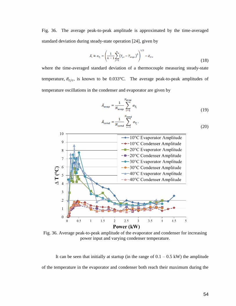
54
Fig. 36. The average peak-to-peak amplitude is approximated by the time-averaged
standard deviation during steady-state operation [24], given by
(18)
where the time-averaged standard deviation of a thermocouple measuring steady-state
temperature, 𝜎𝑡/𝑐, is known to be 0.033°C. The average peak-to-peak amplitudes of
temperature oscillations in the condenser and evaporator are given by
(19)
(20)
Fig. 36. Average peak-to-peak amplitude of the evaporator and condenser for increasing
power input and varying condenser temperature.
It can be seen that initially at startup (in the range of 0.1 – 0.5 kW) the amplitude
of the temperature in the evaporator and condenser both reach their maximum during the

55
inconsistent oscillation period. As the power is increased, the peak-to-peak amplitude for
both the evaporator and condenser begin to decrease and eventually level out and merge.

56
7.0 Conclusion
The experimental investigation of a meter-scale (i.e., 0.915 m) interconnected
layered FP-OHP was carried out to determine the heat transport capability. The prototype
was carefully designed to have 14 turns within a cross section of 31.75 x 6.35 mm2 by
embedding micro channels with a hydraulic diameter of 1.36 mm. The results show that
the FP-OHP was able to transport a maximum power of 4.5 kW with a heat flux of 2.2
kW/cm2. As the power becomes high, the oscillating motion becomes stronger resulting
in a higher heat transport capability. When the power increases, the operating temperature
increases which directly decreases the viscosity resulting in a decrease of pressure drop.
At the same time, when power increases, the driving force increases, which directly
enhances heat transfer. In addition, the FP-OHP is able to successively produce oscillating
motion over a very large power range (0.1 – 4.5 kW) and reaches a minimum resistance of
0.03 K/W (±0.0004 K/W) at a power of 3.75 kW and cooling bath temperature of 40°C. It
has been shown that FP-OHPs can achieve high performance over long transport lengths
with kW heat inputs.

57
8.0 References
1. Ebadian, M. and C. Lin, A review of high-heat-flux heat removal technologies.
Journal of Heat Transfer, 2011. 133(11): p. 110801.
2. Khandekar, S., Thermo-hydrodynamics of closed loop pulsating heat pipes. 2004,
Universitätsbibliothek der Universität Stuttgart: Stuttgart.
3. Arab, M., M. Soltanieh, and M. Shafii, Experimental investigation of extra-long
pulsating heat pipe application in solar water heaters. Experimental Thermal and
Fluid Science, 2012. 42: p. 6-15.
4. Khandekar, S., et al., Local Hydrodynamics of Flow in a Pulsating Heat Pipe: A
Review. Frontiers in Heat Pipes, 2010. 1: p. 20
5. Groll, M. and S. Khandekar, Pulsating Heat Pipes: Progress and Prospects, in
Proceedings of International Conference on Energy and the Environment. 2003:
Shanghai, China.
6. Taft, B.S., A.D. Williams, and B.L. Drolen, Review of Pulsating Heat Pipe Working
Fluid Selection. Journal of Thermophysics and Heat Transfer, 2012. 26(4): p. 651-
656.
7. Zhang, Y., and Faghri, A., Advances and unsolved issues in pulsating heat pipes.
Heat Transfer Engineering, 2008. 29(1): p. 20-44.
8. Dolgirev, Y.E., Y.F. Gerasimov, and A.V. Melkikh, Theoretical and Experimental
Study of Oscillating Heat Pipes with Few Turns. Journal of Engineering Physics
and Thermophysics, 2003. 76(5): p. 996-1000.
9. Charoensawan, P., Khandekar, S., Groll, M., and Terdtoon, P., Closed loop
pulsating heat pipes-Part A: parametric experimental investigations. Applied
Thermal Engineering, 2003. 23: p. 2009-2020.
10. Zhang, Y. and A. Faghri, Advances and Unsolved Issues in Pulsating Heat Pipes.
Heat Transfer Engineering, 2008. 29(1): p. 20-44.
11. Supirattanakul, P., S. Rittidech, and B. Bubphachot, Application of a Closed-Loop
Oscillating Heat Pipe with Check Valves (CLOHP/CV) on Performance
Enhancement in Air Conditioning System. Energy and Buildings, 2011. 43(7): p.
1531-1535
12. Faghri, A., Review and advances in heat pipe science and technology. Journal of
Heat Transfer, 2012. 134(12): p. 123001.
13. Han, X., et al., Investigations on the Heat Transport Capability of a Cryogenic
Oscillating Heat Pipe and its Application in Achieving Ultra-Fast Cooling Rates
for Cell Vitrification Cryopreservation. Cryobiology, 2008. 56(3): p. 195-203.
14. Jiao, A.J., H.B. Ma, and J.K. Critser, Experimental Investigation of Cryogenic
Oscillating Heat Pipes. International Journal of Heat and Mass Transfer, 2009.
52(15-16): p. 3504-3509.
15. Natsume, K., et al., Development of Cryogenic Oscillating Heat Pipe as a New
Device for Indirect/Conduction Cooled Superconducting Magnets. Applied
Superconductivity, IEEE Transactions on, 2012. 22(3): p. 4703904-4703904.
16. Natsume, K., et al., Development of a Flat-plate Cryogenic Oscillating Heat Pipe
for Improving HTS Magnet Cooling. Physics Procedia, 2013. 45: p. 233-236.
17. Natsume, K., et al., Heat Transfer Performance of Cryogenic Oscillating Heat
Pipes for Effective Cooling Of Superconducting Magnets. Cryogenics, 2011. 51(6):
p. 309-314
58
18. Xiao, L. and Y. Cao, Recent advances in pulsating heat pipes and its derivatives.
Journal of Enhanced Heat Transfer, 2012. 19(3).
19. Ma, H., Oscillating Heat Pipes. 2015: Springer New York.
20. Supowit, J., K. Yamada, and I. Catton. Experimental investigation of designer
working fluids in a flat heat pipe. in Thermal Measurement, Modeling &
Management Symposium (SEMI-THERM), 2015 31st. 2015.
21. Pachghare, P.R. and A.M. Mahalle, Effect of pure and binary fluids on closed loop
pulsating heat pipe thermal performance. Procedia Engineering, 2013. 51: p. 624-
629.
22. Zhu, Y., et al., The study on the difference of the start-up and heat-transfer
performance of the pulsating heat pipe with water− acetone mixtures. International
Journal of Heat and Mass Transfer, 2014. 77: p. 834-842.
23. Khandekar, S., Schneider, M., Schafer, P., Kulenovic, R., and Groll, M.,
Thermofluid dynamic study of flat-plate closed-loop pulsating heat pipes.
Microscale Thermophysical Engineering, 2002. 6: p. 303-317.
24. Taft, B., Non-condensable Gases and Oscillating Heat Pipe Operation. Frontiers
in Heat Pipes (FHP), 2013. 4(1).
25. Ito, M., C. Dang, and E. Hihara, Thermal Decomposition of Lower-GWP
Refrigerants. 2014.
26. Peng, H., P.F. Pai, and H. Ma, Nonlinear thermomechanical finite-element
modeling, analysis and characterization of multi-turn oscillating heat pipes.
International Journal of Heat and Mass Transfer, 2014. 69: p. 424-437.
27. Groll, M. and S. Khandekar, Pulsating Heat Pipes: A Challenge and Still Unsolved
Problem In Heat Pipe Science, in The Third International Conference on Transport
Phenomena in Multiphase Systems. 2002: Baranów Sandomierski, Poland. p. 35-
43.
28. Katpradit, T., Wongratanaphisan, T., Terdtoon, P., Kamonpet, P., Polchai, A., and
Akbarzadeh, A., Correlation to predict heat transfer characteristics of a closed end
oscillating heat pipe at critical state. Applied Thermal Engineering, 2005. 25: p.
2138-2151.
29. Sakulchangsatjatai, P., Terdtoon, P., Wongratanaphisan, T., Kamonpet, P., and
Murakami, M., Operation modeling of closed-end and closed-loop oscillating heat
pipes at normal operating condition. Applied Thermal Engineering, 2004. 24: p.
995-1008.
30. Shafii, M.B., A. Faghri, and Y. Zhang, Thermal Modeling of Unlooped and Looped
Pulsating Heat Pipes. Journal of Heat Transfer, 2001. 123(6): p. 1159-1172
31. Han, H., et al., A comparative study of the behavior of working fluids and their
properties on the performance of pulsating heat pipes (PHP). International Journal
of Thermal Sciences, 2014. 82: p. 138-147.
32. Qu, J. and H. Wu, Flow visualization of silicon-based micro pulsating heat pipes.
Science China Technological Sciences, 2010. 53(4): p. 984-990.
33. Ma, H.B., Wilson, C., Yu, Q., Park, K., Choi, U.S., and Tirumala, M., An
experimental investigation of heat transport capability in a nanofluid oscillating
heat pipe. Journal of Heat Transfer, 2006. 128: p. 1213-1216.
34. Cheng, P., et al., An Investigation of Flat-Plate Oscillating Heat Pipes. Journal of
Electronic Packaging, 2010. 132(4): p. 041009-041009.

59
35. Qu, J., Wu, H., and Cheng, P., Thermal performance of an oscillating heat pipe
with Al2O3–water nanofluids. International Communications in Heat and Mass
Transfer, 2010. 37: p. 111-115.
36. Ji, Y., et al., Particle Shape Effect on Heat Transfer Performance in an Oscillating
Heat Pipe. Experimental Thermal and Fluid Science, 2011. 35(4): p. 724-727
37. Li, Q.-M., et al., Visualization of two-phase flows in nanofluid oscillating heat
pipes. Journal of Heat Transfer, 2011. 133(5): p. 052901.
38. Riehl, R.R. and N.d. Santos, Water-Copper Nanofluid Application in an Open Loop
Pulsating Heat Pipe Applied Thermal Engineering, 2011.
39. Zhao, J.-J., et al., Effect of nanofluids on thin film evaporation in microchannels.
Journal of Nanoparticle Research, 2011. 13(10): p. 5033-5047.
40. Gu, J., M. Kawaji, and R. Futamata, Microgravity Performance of Micro Pulsating
Heat Pipes. Microgravity Science and Technology, 2005. 16(1): p. 181-185.
41. Lin, Y.H., S.W. Kang, and T.Y. Wu, Fabrication of Polydimethylsiloxane (PDMS)
Pulsating Heat Pipe. Applied Thermal Engineering, 2009. 29(2-3): p. 573-580
42. Hisoda, M., S. Nishio, and R. Shirakashi, Study of Meandering Closed-Loop Heat-
Transport Device. Vapor-Plug Propagation Phenomena. JSME International
Journal Series B, 1999. 42(4): p. 737-744.
43. Lin, Z., et al., Experimental Study on Effective Range of Miniature Oscillating Heat
Pipes. Applied Thermal Engineering, 2011. 31(5): p. 880-886
44. Yang, H., S. Khandekar, and M. Groll, Performance Characteristics of Pulsating
Heat Pipes as Integral Thermal Spreaders. International Journal of Thermal
Sciences, 2009. 48(4): p. 815–824.
45. Anuchitchanchai, P., et al. Effect of aspect ratios and internal diameter on
performance limit of a closed-end oscillating heat pipe using refrigerant blend as
working fluid. in Proceeding of the 7th International Heat Pipe Symposium, Jeju-
Do, Korea. 2003.
46. Katpradit, T., et al., Effect of Aspect Ratios and Bond Number on Internal Flow
Patterns of Closed End Oscillating Heat Pipe at Critical State, in 13th International
Heat Pipe Conference. 2004: Shanghai, China. p. 298-303.
47. Yang, K.-S., et al., Micro pulsating heat pipes with alternate microchannel widths.
Applied Thermal Engineering, 2015. 83: p. 131-138.
48. Wilson, C., et al., Thermal and Visual Observation of Water and Acetone
Oscillating Heat Pipes. Journal of Heat Transfer, 2011. 133(6): p. 061502-5.
49. Jun, S. and S.J. Kim, Comparison of Thermal Performance and Flow
Characteristics Between the Closed-Loop and Closed-End Pulsating Heat Pipes,
in 9th International Conference on Boiling and Condensation Heat Transfer. 2015:
Boulder, CO, USA.
50. Yang, H., S. Khandekar, and M. Groll, Performance Comparison of Open Loop
and Closed Loop Pulsating Heat Pipes, in 8th International Heat Pipe Symposium.
2006: Kumamoto, Japan.
51. Cai, Q., Chen, C.L., and Asfia, J.F., Operating characteristic investigations in
pulsating heat pipe. Journal of Heat Transfer, 2006. 128: p. 1329-1334.
52. Zhao, N., D. Zhao, and H. Ma, Experimental Investigation of Magnetic Field Effect
on the Magnetic Nanofluid Oscillating Heat Pipe. Journal of Thermal Science and
Engineering Applications, 2013. 5(1): p. 011005-011005.

60
53. Borgmeyer, B., Wilson, C., Winholtz, R.A., Ma., H.B., Jacobson, D., and Hussey,
D., Heat transport capability and fluid flow neutron radiography of three-
dimensional oscillating heat pipes. Journal of Heat Transfer, 2010. 132.
54. Thompson, S.M., P. Cheng, and H.B. Ma, An Experimental Investigation of a
Three-Dimensional Flat-Plate Oscillating Heat Pipe with Staggered
Microchannels. International Journal of Heat and Mass Transfer, 2011. 54(17-18):
p. 3951-3959
55. Smoot, C.D. and H.B. Ma, Experimental Investigation of a Three-Layer Oscillating
Heat Pipe. Journal of Heat Transfer, 2014. 136(5): p. 051501-051501.
56. Hathaway, A., C. Wilson, and H. Ma, Experimental investigation of uneven-turn
water and acetone oscillating heat pipes. Journal of Thermophysics and Heat
Transfer, 2012. 26(1): p. 115-122.
57. Chien, K.-H., et al., A novel design of pulsating heat pipe with fewer turns
applicable to all orientations. International journal of heat and mass transfer, 2012.
55(21): p. 5722-5728.
58. Akachi, H., Structure of a heat pipe. 1990, Actronics Kabushiki Kaisha: United
States.
59. Bhuwakietkumjohn, N. and S. Rittidech, Internal Flow Patterns on Heat Transfer
Characteristics of a Closed-Loop Oscillating Heat-Pipe with Check Valves Using
Ethanol and a Silver Nano-Ethanol Mixture. Experimental Thermal and Fluid
Science, 2010. 34(8): p. 1000-1007.
60. Thompson, S.M., Ma, H.B., and Wilson, C., Investigation of a flat-plate osciillating
heat pipe with Tesla-type check valves. Experimental Thermal and Fluid Science,
2011.
61. Park, K. and H.B. Ma, Nanofluid Effect on Heat Transport Capability in a Well-
Balanced Oscillating Heat Pipe. Journal of Thermophysics and Heat Transfer,
2007. 21(2): p. 443-445
62. Melkikh, A. and Y. Dolgirev, Self-Oscillations in Oscillating Heat Pipes. High
Temperature, 2006. 44(4): p. 542-547
63. Charoensawan, P., and Terdtoon, P., Thermal performance of horizontal closed-
loop oscillating heat pipes. Applied Thermal Engineering, 2008. 28: p. 460-466.
64. Faghri, A., Heat Pipe Science And Technology. 1995: Taylor & Francis.
65. Peterson, G.P., An Introduction to Heat Pipes: Modeling, Testing, and
Applications. 1994: John Wiley & Sons.
66. Reay, D., R. McGlen, and P. Kew, Heat Pipes: Theory, Design and Applications.
2013: Elsevier Science.
67. Senjaya, R. and T. Inoue, Effects of non-condensable gas on the performance of
oscillating heat pipe, part I: Theoretical study. Applied Thermal Engineering,
2014. 73(1): p. 1387-1392.
68. Senjaya, R. and T. Inoue, Effects of non-condensable gas on the performance of
oscillating heat pipe, part II: Experimental study. Applied Thermal Engineering,
2014. 73(1): p. 1393-1400.
69. Brennan, P.J. and E.J. Kroliczek, Heat pipe design handbook. 1979: NASA
Goddard Space Flight Center.
61
70. Hsieh, J.-C., et al., An experimental study on the compatibility of acetone with
aluminum flat-plate heat pipes. Heat and Mass Transfer, 2014. 50(11): p. 1525-
1533.
71. Habonim, Chemical Compatibility Guide. 2013.
72. Anderson, W.G., et al. Intermediate temperature fluids for heat pipes and loop heat
pipes. in Proceedings of the international energy conversion engineering
conference, St. Louis, MO. 2007.
73. UK_Copper_Board, Guide to the Suitability of Copper with Various Chemicals.
2014. p. 50.
74. Feynman, R.P., R.B. Leighton, and M. Sands, Feynman lectures on physics. vol. 1:
Mainly mechanics, radiation and heat. 1963: Addison-Wesley.
75. Norton, J., Cold Welding Ductile Metal Tubulation. 2013, Custom Products &
Services, Inc. p. 6.
76. Verthier, B., A310 zero-g interfaces document. 2014, Novespace.
77. Del Rosso, D.L., Interface Control Document. 2011, NASA Aircraft Operations
Division: Houston, TX.
78. Gu, J., M. Kawaji, and R. Futamata, Effects of Gravity on the Performance of
Pulsating Heat Pipes. Journal of Thermophysics and Heat Transfer, 2004. 18(3): p.
370-378.
79. Mameli, M., et al., Thermal response of a closed loop pulsating heat pipe under a
varying gravity force. International Journal of Thermal Sciences, 2014. 80: p. 11-
22.
80. Harirchian, T. and S.V. Garimella, A comprehensive flow regime map for
microchannel flow boiling with quantitative transition criteria. International
Journal of Heat and Mass Transfer, 2010. 53(13–14): p. 2694-2702.
81. Taft, B.S., et al., Microgravity Performance of a Structurally Embedded Oscillating
Heat Pipe. Journal of Thermophysics and Heat Transfer, 2015. 29(2): p. 329-337.
82. Mangini, D., et al., A pulsating heat pipe for space applications: Ground and
microgravity experiments. International Journal of Thermal Sciences, 2015. 95: p.
53-63.
83. Creatini, F., et al., Pulsating Heat pipe Only for Space (PHOS): results of the
REXUS 18 sounding rocket campaign. Journal of Physics: Conference Series, 2015.
655(1): p. 012042.
84. Okamoto, A., M. Ando, and H. Sugita, Initial Evaluation of On-Orbit Experiment
of Flat-Plate Heat Pipe, in 17th International Heat Pipe Conference. 2013: Kanpur,
India. p. 1-8.
85. Maeda, M., et al. Development of Flat Plate Heat Pipe and the Project of On-orbit
Experiment. in 41st International Conference on Environmental Systems. 2011.
86. Rittidech, S., and Wannapakne, S., Experimental study of the performance of a
solar collector by closed-end oscillating heat pipe (CEOHP). Applied Thermal
Engineering, 2007. 27: p. 1978-1985.
87. Okazaki, S., et al., Development of Meter-Scale U-Shaped and O-Shaped
Oscillating Heat Pipes for GAPS. Journal of Astronomical Instrumentation, 2014.
3(02): p. 1440004.