Embed Size (px)
Citation preview

An Evaluation of Confocal Versus Conventional Imaging of Biological Structures by Fluorescence Light Microscopy J. G. White, W. B. Amos, a n d M. Fordham Medical Research Council Laboratory of Molecular Biology, Hills Road, Cambridge CB2 2QH, United Kingdom
Abstract. Scanning confocal microscopes offer improved rejection of out-of-focus noise and greater resolution than conventional imaging. In such a micro- scope, the imaging and condenser lenses are identical and confocal. These two lenses are replaced by a single lens when epi-illumination is used, making confocal imaging particularly applicable to incident light microscopy. We describe the results we have ob- tained with a confocal system in which scanning is
performed by moving the light beam, rather than the stage. This system is considerably faster than the scanned stage microscope and is easy to use. We have found that confocal imaging gives greatly enhanced images of biological structures viewed withepifluores- cence. The improvements are such that it is possible to optically section thick specimens with little degra- dation in the image quality of interior sections.
PIFLUORESCENCE has become one of the most com- monly used microscopic techniques in biological re- search: it has contributed to the current renaissance
in light microscopy. Part of the reason for this is the develop- ment of immunofluorescence, where the exquisite chemical specificity of antibodies is used as a basis for staining. Also, new fluorescent probes have been introduced, such as those that indicate the intracellular concentration of calcium ions (Tsien et al., 1985), intraceUular pH (Paradiso et al., 1987), or membrane potential (Ross et al., 1977). Furthermore, the microinjection of fluorescently labeled proteins and lipids is increasingly used as an experimental strategy (Taylor et al., 1984).
A severe problem with epifluorescence is the unwanted contribution of signals from structures above and below the plane of focus: this produces a background glow that de- grades the image. Several means have been used to circum- vent this difficulty. One is the use of flattened cells, but this shape is rare in nature and almost never maintained during cell division. The cutting of sections is another solution, but introduces technical difficulties as well as problems in inter- preting three-dimensional structure. Recently, computer de- convolution techniques have been used to enhance images of through-focal series (Agard and Sedat, 1983) and have made considerable improvements in the quality of images obtained from thick specimens. However, such techniques are com- putationally intensive and do not give immediate results.
It has been demonstrated both theoretically and practically that confocal imaging reduces interference from out-of-focus structures (Sheppard and Wilson, 1982; Wilson and Shep- pard, 1984). Recently it has been shown that this method can produce excellent epifluorescent images in which out-of- focus fluorescence is virtually eliminated (Brakenhoff et al., 1985; Wijnaendts van Resandt et al., 1985). Confocal imag-
ing is a technique in which an object is illuminated with a small (diffraction limited) spot, usually derived from a fo- cused laser beam. The illuminated spot is viewed with a spa- tially restricted optical system so that only signals emanating from this spot are detected. An image of the complete speci- men is built up by a raster scan. Both the intensity of illu- mination and the sensitivity of the detector fall rapidly with distance away from the plane of focus. This contrasts with conventional epifluorescence methods, where the specimen is bathed in an essentially uniform flux of excitatory illumi- nation.
Another advantage of confocal imaging is that the effective point spread function of the system is reduced, since it is the product of the point spread functions of the illuminating and objective lenses (Sheppard and Wilson, 1982). This gives a theoretical improvement in resolution by a factor of 1.4, which has been realized experimentally by Brakenhoff and his colleagues (1979).
The confocal microscopes that have been described so far use fixed optics and raster scan the specimen by moving the mechanical stage (Brakenhoff et ai., 1979). Because of the difficulties of mechanically translating the microscope stage at high speed these instruments have slow scan times, typi- cally of the order of 10 s per image. They also cannot image the object conventionally and so there is no direct way of viewing the specimen. This, combined with the slow scan speed, is a serious disadvantage, since a microscopist almost invariably needs to locate an object of interest within an ex- tensive area.
A high speed system in which the beam is scanned by means of a Nipkow disc has been described (P6trah et al., 1968). Unfortunately, this elegant system is not ideal for epifluorescence as only a small fraction of the illuminating beam is used. Laser scanning microscopes have recently
© The Rockefeller University Press, 0021-9525/87/07/41/8 $2.00 The Journal of Cell Biology, Volume 105, July 1987 41--48 41
Dow
nloaded from http://rupress.org/jcb/article-pdf/105/1/41/1055159/41.pdf by guest on 02 D
ecember 2021
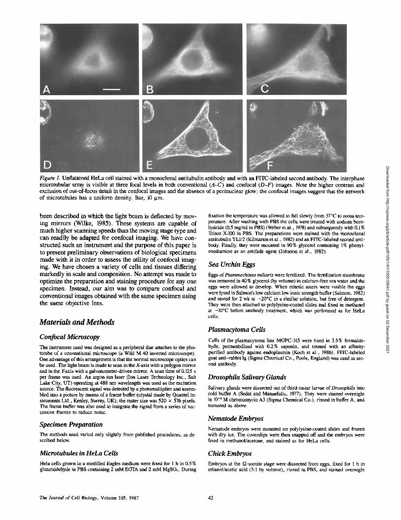
Figure 1. Unflattened HeLa cell stained with a monoclonal antitubulin antibody and with an FITC-labeled second antibody. The interphase microtubular array is visible at three focal levels in both conventional (A-C) and confocal (D-F) images. Note the higher contrast and exclusion of out-of-focus detail in the confocal images and the absence of a perinuclear glow; the confocal images suggest that the network of microtubules has a uniform density. Bar, 10 Ixm.
been described in which the light beam is deflected by mov- ing mirrors (Wilke, 1985). These systems are capable of much higher scanning speeds than the moving stage type and can readily be adapted for confocal imaging. We have con- structed such an instrument and the purpose of this paper is to present preliminary observations of biological specimens made with it in order to assess the utility of confocal imag- ing. We have chosen a variety of cells and tissues differing markedly in scale and composition. No attempt was made to optimize the preparation and staining procedure for any one specimen. Instead, our aim was to compare confocal and conventional images obtained with the same specimen using the same objective lens.
Materials and Methods
Confocal Microscopy The instrument used was designed as a peripheral that attaches to the pho- totube of a conventional microscope (a Wild M 40 inverted microscope). One advantage of this arrangement is that the normal microscope optics can be used. The light beam is made to scan in the X-axis with a polygon mirror and in the Y-axis with a galvanometer-driven mirror. A scan time of 0.125 s per frame was used. An argon ion laser (Ion Laser Technology Inc., Salt Lake City, UT) operating at 488 nm wavelength was used as the excitation source. The fluorescent signal was detected by a photomultiplier and assem- bled into a picture by means of a frame buffer (crystal made by Quantel In- struments Ltd., Kenley, Surrey, UK); the raster size was 520 x 576 pixels. The frame buffer was also used to integrate the signal from a series of suc- cessive frames to reduce noise.
Specimen Preparation The methods used varied only slightly from published procedures, as de- scribed below.
Microtubules in HeLa Cells Hela cells grown in a modified Eagles medium were fixed for 1 h in 0.5% glutaraldehyde in PBS containing 2 mM EGTA and 2 mM MgSO4. During
fixation the temperature was allowed to fall slowly from 37°C to room tem- perature. After washing with PBS the cells were treated with sodium boro- hydride (0.5 mg/ml in PBS) (Weber et al., 1978) and subsequently with 0.1% Triton X-D0 in PBS. The preparations were stained with the monoclonal antitubulin YL1/2 (Kilmartin et al., 1982) and an FITC-labeled second anti- body. Finally, they were mounted in 90% glycerol containing 1% phenyl- enediamine as an antifade agent (Johnson et al., 1982).
Sea Urchin Eggs Eggs of Psammechinus miliaris were fertilized. The fertilization membrane was removed in 40% glycerol (by volume) in calcium-free sea water and the eggs were allowed to develop. When mitotic asters were visible the eggs were lysed in Salmon's low calcium low ionic strength buffer (Salmon, 1982) and stored for 2 wk at - 20°C in a similar solution, but free of detergent. They were then attached to polylysine-coated slides and fixed in methanol at -10°C before antibody treatment, which was performed as for HeLa cells.
Plasmacytoma Cells Cells of the plasmacytoma line MOPC-315 were fixed in 3.5% formalde- hyde, permeabilized with 0.2% saponin, and treated with an afffinity- purified antibody against endoplasmin (Koch et al., 1986). FITC-labeled goat anti-rabbit Ig (Sigma Chemical Co., Poole, England) was used as sec- ond antibody.
Drosophila Salivary Glands Salivary glands were dissected out of third-instar larvae of Drosophila into cold buffer A (Sedat and Manuelidis, 1977). They were stained overnight in 10 -4 M chromomycin A3 (Sigma Chemical Co.), rinsed in buffer A, and mounted as above.
Nematode Embryos Nematode embryos were mounted on polylysine-coated slides and frozen with dry ice. The coverslips were then snapped off and the embryos were fixed in methanol/acetone, and stained as for HeLa cells.
Chick Embryos Embryos at the 12-somite stage were dissected from eggs, fixed for 1 h in ethanol/acetic acid (3:1 by volume), rinsed in PBS, and stained overnight
The Journal of Cell Biology, Volume 105, 1987 42
Dow
nloaded from http://rupress.org/jcb/article-pdf/105/1/41/1055159/41.pdf by guest on 02 D
ecember 2021

Figure 2. A mitotic spindle in a HeLa cell stained as in Fig. 1. A conventional image is shown in A, with, for comparison, a confocal image taken at a similar level of focus (B). Other confocal images at different levels are shown in C-E Note the spots in D and E that probably represent optical sections of individual microtubules or small bundles, and the dark images of chromosomes. Bar, 5 p.m.
in chromomycin A3 (Sigma Chemical Co.). The embryos were mounted and mounted in Gurr's Fluoromount (BDH Chemicals Ltd., Poole, En- whole in the same mountant as the HeLa cells, gland).
Drosophila Neurones Individual neurones in ganglia of Drosophila pupae were microinjected with the fluorescent dye Lucifer Yellow. Ganglia from larvae were backfilled via cut nerves with the same dye. The ganglia were dehydrated, cleared,
Results
It was found that in all cases the confocal image was superior to the conventional one in terms of contrast and lack of out-
White et al. Confocal Beam-Scan Epifluqeescence 43
Dow
nloaded from http://rupress.org/jcb/article-pdf/105/1/41/1055159/41.pdf by guest on 02 D
ecember 2021

Figure 3. Fertilized egg of a sea urchin (Psammechinus) stained with antitubulin. (A) Conventional image for comparison with (B) confocal. Note the improved detail in the confocal image at the pe- riphery and in the mitotic centers. Bar, 50 Ixm.
of-focus interference. The degree of improvement depended on the specimen, being most pronounced in specimens where the stained structures were present at high density and dispersed in three dimensions and least pronounced when they were few or restricted to a single plane.
The interphase array of microtubules in a relatively unflat- tened tissue culture cell (Fig. 1) showed the improvements clearly. In particular, the background glow due to out-of- focus fluorescence in the perinuclear region was eliminated, giving an impression of a more uniform density of microtu- bules throughout the cytoplasm.
The mitotic spindles of HeLa cells (which measure only 6 Ixm between poles) represent a difficult object for conven- tional microscopy: antitubulin staining yields images in which the spindle may appear almost uniformly bright except at the periphery (Fig. 2 A). By comparison, the confocal images showed a wealth of detail, varying according to the selected plane of focus (Fig. 2, B-F). Bright spots that are probably optical sections of individual microtubules or small bundles were seen (Fig. 2, D and E), and lines, probably represent- ing individual tubules, were observed, some crossing over each other at various angles. The chromosomes were also distinguishable as dark regions (Fig. 2 D). Similar improve- ments were also obtained with the dense microtubule array of the dividing sea urchin egg (Fig. 3).
Figure 4. A spherical plasmacytoma cell (line MOPC-315) stained with an antibody against endoplasmin (Koch et al., 1986). A shows the conventional image of a median optical section through the cell, B the equivalent confocal image, showing parallel concentric bright lines that probably correspond to sections of individual cistemae of the endoplasmic reticulum. Bar, 10 gm.
In many cases the improvements were dramatic, enabling structures to be seen within the cell that could not be detected by conventional means One example is the perinuclear orga- nization of the endoplasmic reticulum in plasmaeytoma cells (Fig. 4 B). In these spherical cells, the confocal image of a median optical section shows bright concentric lines, which probably represent sections of individual cisternae of the reticulum arranged parallel to the nuclear membrane. These could not be se n at all in the conventional image (Fig. 4 A). Even clearer images havebeen obtained with our microscope of the endoplasmic reticulum in flattened cells of a different cell line (Munro and Pelham, 1987).
The polytene chromosomes in the nuclei of salivary glands of Drosophila were examined in order to make possible a comparison with previous work: this material has been ex- tensively studied by workers seeking to reconstruct the three- dimensional arrangement of the chromosomes, using com- puter enhance ent of the conventioual image (Agard and Sedat, 1983). Because of the restriction in excitation wave-
The Journal of Cell Biology, Volume 105, 1987 44
Dow
nloaded from http://rupress.org/jcb/article-pdf/105/1/41/1055159/41.pdf by guest on 02 D
ecember 2021

Figure 5. Intact but slightly flattened nuclei in preparations of salivary glands of Drosophila larvae. The polytene chromosomes are revealed by staining with chromomycin A3. A and B are confocal and conventional images obtained from similar levels of focus; the confocal image shows improvements in the definition and contrast of the banded chromosomal structure. C-J is a series of confocal images taken through a single nucleus at successively deeper focal levels. The magnification in C-J is half that of A and B, but the same objective was used throughout. Bar, 10 ~tm.
length in our instrument to 488 nm, chromomycin A3 was used as the DNA-specific fluorochrome instead of DAPI which was often used previously. From a single nucleus (Fig. 5, C-J) a series of optical sections could be obtained. Each of the sections showed greater contrast and resolution than
the conventional equivalent (cf. Fig. 5 A with Fig. 5 B). In- deed the confocal image resembles the enhanced images ob- tained by Gruenbaum et al. (1984) by computational decon- volution techniques.
A number of multiceUular specimens were examined, in
White et al. Confocal Beam-Scan Epifluorescence 45
Dow
nloaded from http://rupress.org/jcb/article-pdf/105/1/41/1055159/41.pdf by guest on 02 D
ecember 2021

Figure 6. (A-C) Whole mount of an embryo of Caenorhabditis elegans stained with antitubulin and an FITC-labeled second antibody. The conventional image (A) is for comparison with a confocal image (B) and the same confocai image subjected to spatial filtering (C). (D-E) Median horizontal optical section through part of the head region of a chick embryo at the 12-somite stage. The numerous bright bodies are nuclei, stained with the DNA-specific fluorochrome chromomycin A3. The confocal image (E) shows better definition and con- trast of the cell layers of the optic vesicle, lens ectoderm, and amnion, even though the conventional image (D) was brought to the highest possible contrast during printing of the negative. (F and G) Single neurone within a ganglion of a Drosophila pupa, microinjected with the fluorescent dye Lucifer Yellow. The confocal image (G) reveals numerous dendrites, scarcely visible in the conventional image (F). (H and 1) Conventional (H) and confocal (I) images of an intact Drosophila ganglion, showing numerous cell bodies and axons, back filled with Lucifer Yellow. Bars: (A-C, F and G) 25 lira; (D-E) 100 Ixm; (H and I) 50 ~tm.
The Journal of Ceil Biology, Volume 105, 1987 46
Dow
nloaded from http://rupress.org/jcb/article-pdf/105/1/41/1055159/41.pdf by guest on 02 D
ecember 2021

order to assess the advantages of confocal imaging with thick specimens. It proved possible to explore in detail the mitotic spindle architecture of intact nematode embryos (Fig 6, A- C) as revealed by antitubulin staining (Hyman, A., and J. J. White, manuscript submitted for publication). As in the pre- vious examples, an objective lens of high NA (1.3) was used.
Theoretically, the thickness of the in focus region is a func- tion of the NA of the lens as in conventional microscopy. With lenses of NA 1.3 optical sections of ,'00.7 Ima may be obtained with confocal imaging (Brakenhoff et al., 1979). It was therefore of interest to see whether the confocal method would give any advantage when objectives of lower NA must, of necessity, be used (e.g., for low magnifications or thick specimens where the working distance is long). The chick embryo was examined with a x6.3 objective (NA 0.2). The optical sections (Fig. 6, D and E) taken within the head of the intact embryo show that confocal imaging is advanta- geous even in this situation. The confocal image is sharp and high in contrast in spite of the overlying thickness of 0.5 mm of fluorescent tissue, whereas the conventional image was so blurred that detail could be recorded photographically only with difficulty. Similar advantages were seen with neurones filled with the fluorescent dye Lucifer Yellow (Fig. 6, F-l). The presence of the intact ganglion around the neurones seri- ously impaired definition in the conventional images (Fig. 6, F and H): far greater detail of axons and dendrites was visi- ble in the confocal images (Fig 6, G and I).
We observed that when thick objects were optically sec- tioned in the confocal system, the limit to depth of sectioning was set by a falloff of intensity rather than by degradation of image quality. The falloff is presumably due to attenuation of the incident exciting and emergent fluorescent beams as they pass through the structure.
It is often a source of frustration, when using conventional epifluorescence, that structures can be seen visually yet can- not be captured on film. This is because the eye can discern small changes in intensity superimposed on a high back- ground if these changes have high spatial frequency com- ponents. The limited dynamic range of film makes such structures hard to photograph. By essentially removing the background out-of-focus components in an image, the confo- cal system made it possible to record such features on film without difficulty.
Preparations that would generally be considered to be overstained or to have unacceptably high levels of back- ground staining often appeared much better in the confocal system. Indeed, we found it advantageous to deliberately overstain, as judged by the criterion of the conventional image.
We found that bleaching was largely restricted to the focal plane being viewed, unlike the case with conventional mi- croscopy where the whole cell becomes uniformly bleached. When FITC was used, optimum results were obtained when the power of the argon ion laser was attenuated to 2 mW. At this level, photobleaching was approximately half as fast as in a conventional epifluorescence system. Interestingly, higher levels of excitation seemed to degrade the image qual- ity in a characteristic way: lightly stained regions increased disproportionately in brighmess, yielding an image of re- duced contrast. This may be due to some saturation effect that occurs at the very high instantaneous light fluxes (about 250,000x conventional) near the focus of the scanning laser
beam. Chromomycin, which has maximum excitation at 440 nm, is inefficiently excited by the 488-nm laser light and we found that with this fluorochrome full power could be used with no apparent degradation in image quality (Fig. 5).
The confocal imaging system was ~2.4 times more sensi- tive than direct photography. Optimum confocal images were obtained after integrating for around 100 frames, corre- sponding to an exposure of 12.5 s at the scanning rate of 8 frames per second. After this the beam could be turned off as the image was held in the frame store. The corresponding exposure time needed in a conventional microscope with a mercury arc source was '~30 s. When compared with a high- sensitivity television camera such as a silicon intensified tar- get (SIT) or intensified silicon intensified target (ISIT) cam- era, the confocal system was less sensitive. However, images from SIT and ISIT cameras cannot be usefully integrated over periods >,,020 s because of the relatively high levels of dark current and structured background noise inherent in these devices. In contrast, we found that it was possible to integrate images from the confocal system over a period of several minutes before the dark current of the photomul- tiplier became a problem. The confocal system is therefore able to detect signals of the same order of intensity as an ISIT camera, although with a higher integrated dose of exciting radiation. Generally, we found it easier to obtain images of reproducible exposure and contrast with the confocal system than with ordinary photography, since the integration could be allowed to continue automatically until peak white was at- tained somewhere on the screen and the film camera was per- manently set to encompass the intensity range from black to peak white.
Precise measurements of resolution in the plane of focus and along the optical axis are difficult to achieve, particularly in fluorescence systems. Detail at a resolution of 200 nm was visible in many of the confocal images (e.g., Fig. 5), but no attempt was made in the present work to separate the im- provement due to optical resolution from that due to in- creased contrast.
Operationally, the confocal imaging system proved easy to use: it was no more difficult than using a video camera on an ordinary microscope. The visual impression was, how- ever, quite novel, since the screen was completely black when the specimen was out of focus. The potential inconve- nience in locating specimens was not a serious problem, since, if necessary, the specimen could be located by viewing it directly in bright field before switching to the confocal im- aging mode.
Discussion
Confocal imaging has been demonstrated both theoretically and practically to give improved visibility of optical sections and improved resolution. These advantages are particularly apparent when the method is used with epifluorescence be- cause this type of visualization is seriously impaired by out- of-focus signal. We have demonstrated that a high speed beam-scanning laser confocal microscope can be used to good effect with a variety of cells and tissues. With all the specimens we have examined so far (including much material not described here) the confocal image has shown more use- able information than its conventional counterpart.
We have confirmed the previous demonstrations (e.g.,
White et al, Confocal Beam-ScanEpifluorescence 47
Dow
nloaded from http://rupress.org/jcb/article-pdf/105/1/41/1055159/41.pdf by guest on 02 D
ecember 2021

Brakenhoff et al., 1979; Wijnaendts van Resant et al., 1985) that detail at a resolution of 200 nm can be seen in the confo- cal images when an objective of high NA is used. To avoid loss of detail, this distance must span at least two lines in the video image. Consequently, the video system at present sets a lower limit to the optimum magnification, with a corre- sponding maximum coverage of field. Replacement of our 500 line video system with 1,000 line system would allow the use of lower magnifications without loss of detail.
Our instrument is used as an adjunct to a conventional mi- croscope and this increases its usefulness in practice, be- cause of the ease of alternating between normal and confocal modes. Such devices are likely to be commercially available s o o n .
As described above, good images have been obtained from old or badly stained immunofluorescence preparations in which there is a high level of nonspecific staining. This, to- gether with the success of chromomycin as a microanatomi- cal stain (Fig. 6 E), suggests that it may well be possible to use fluorescent dyes in the same way as the classical histolog- ical stains. It seems likely that optical confocal sectioning of whole mounts may prove a preferable alternative to the prep- aration of frozen sections.
The powerful new techniques for visualizing intraceUular calcium ion levels, pH, and other parameters would greatly benefit from confocal imaging. In particular, more accurate quantitative data should be obtainable for the mapping of these parameters in three dimensions, because of the exclu- sion of signals from out-of-focus regions.
Since the images produced by the confocal system are held in a digital frame store they are readily available for com- puter analysis. Deconvolution techniques such as those used by Agard and Sedat (1983) or the maximum entropy tech- niques described by Gull and Skilling (1984) could readily be applied. It should then be possible to obtain even further enhancement in resolution and signal-to-noise ratio. The confocal optical sections have been shown to be ideal for three-dimensional reconstruction from a series taken at suc- cessive levels of focus (Wijnaendts van Resandt et al., 1985) of the type previously carried out from conventional images (Skaer and Whytock, 1975; Agard and Sedat, 1983).
The relatively high sensitivity of a confocal imaging sys- tem that uses a photomultiplier detector opens up the exciting possibility of being able to visualize the changes in cytoar- chitecture that occur in living cells.
We thank Tony Hyman, Gordon Koch, Olav Sundin, and Mike Bate for their generous help in providing specimens for microscopy, and Richard Durbin and Mike Thompson for collaboration in optical and electronic aspects of the development of the confocal scanning system.
Received for publication 18 February 1987.
Referencss
Agard, D. A., and J. W. Sedat. 1983. Three-dimensional architecture ofa poly- tene nucleus. Nature (Lond.). 302:676-681.
Brakenhoff, G. J., P. Biota, and P. Barends. 1979. Confocal scanning light mi- croscopy with high aperture immersion lenses. J. Microsc. (Oxf.). 117:219- 232.
Brakenhoff, G. J., H. T. M. van der Voort, E. A. van Sprousen, W. A. M. Linnemans, and N. Nanninga. 1985. Three-dimensional chromatin distribu- tion in neuroblastoma nuclei shown by confocal scanning laser microscopy. Nature (Lond.). 317:748-749.
Gmenbaum, Y., M. Hochstrasser, D. Mathog, H. Saumweber, D. A. Agard, and J. W. Sedat. 1984. Spatial organisation of the Drosophila nucleus: a three-dimensional cytogenetic study. J. Cell Sci. l(Suppl.):223-234.
Gull, S. F., and J. Skilling. 1984. Maximum entropy method in image process- ing. 1. E. E. Proc. 131F:646-659.
Johnson, G. D., R. S. Davidson, K. C. McNamee, G. Russell, D. Goodwin, and E. J. Holborow. 1982~ Fading of immunofluorescence during micros- copy: a study of the phenomenon and its remedy. J. lmmunol. Methods. 55:231-242.
Kilmartin, J. V., B. Wright, and C. Milstein. 1982. Rat monoclonal antitubulin antibodies derived by using a new nonsecreting rat cell line. J. Cell Biol. 93:576-582.
Koch, G., M. Smith, D, Macer, P. Webster, and R. Mortara. 1986. Endoplas- mic reticulum contains a common, abundant calcium-binding glycoprotein, endoplasmin. J. Cell Sci. 86:217-232.
Munro, S., and H. R. B. Pelham. 1987. A C-terminal signal prevents secretion of luminal ER proteins. Cell. 48:899-907.
Paradise, A. M., R. Y. Tsien, and T. E. Machen. 1987. Digital image process- ing of intracellular pH in gastric oxyntic and chief cells. Nature (Lond.). 325:447-450.
Pttran, M., M. Hadravsk~, M. D. Egger, and R. Galambos. 1968. Tandem- scanning reflected-light microscope. J. Opt. Soc. Am. 58:661-664.
Ross, W. N., B. M~ Salzberg, L. B. Cohen, A. Grinvald, H. V. Davila, A. S. Waggoner, and C. H. Wang. 1977. Changes in absorption, fluorescence, dichroism and birefringence in stained giant axon: optical measurement of membrane potential. J. Membr. Biol. 33:141-183.
Salmon, E. D. 1982. Mitotic spindles isolated from sea urchin eggs with EGTA lysis buffers. Methods Cell Biol. 25:69-105.
Sedat, J. W., and L. Manuelidis. 1977. A direct approach to the structure of eukaryotic chromosomes. Cold Spring Harbor Syrup. Quant. Biol. 42:331- 350.
Sheppard, C. J. R., and T. Wilson. 1982. The image of a single point in micro- scopes of large numerical aperture. Proc. R. Soc. Lond. A. Phys. Sci. A379: 145-158.
Skaer, R. J., and S. Whytock. 1975. Interpretation of the three-dimensional structure of living nuclei by specimen tilt. J. Cell Sci. 19:1-10.
Taylor, D. L., P. A. Amato, K. Luby-Phelps, and P. McNeil. 1984. Fluores- cent analog cytochemistry. Trends Biochem. Sci. 9:88-91.
Tsien, R. Y., T. J. Rink, and M. Poenie. 1985. Measurement ofcytosolic free Ca 2+ in individual small cells using fluorescence microscopy with dual exci- tation wavelengths. Cell Calcium. 6:145-157.
Weber, K., P. C. Rathke, and M. Osborn. 1978. Cytoplasmic microtubular im- ages in glutaraldehyde-fixed tissue culture cells by electron microscopy and by immunofluorescence microscopy. Proc. Natl. Acad. Sci. USA. 75:1820- 1824.
Wijnaendts van Resandt, R. W., H. J. B. Marsman, R. Kaplan, J. Davoust, E. H. K. Stelzer, and R. Striker. 1985. Optical fluorescence microscopy in three dimensions: microtomoscopy. J. Microsc. 138:29-34.
Wilke, V. 1985. Optical scanning microscopy-the laser scan microscope. Scanning. 7:88-96.
Wilson, T., and C. J. R. Sheppard. 1984. Theory and Practice of Scanning Op- tical Microscopy. Academic Press, Inc., New York.
The Journal of Cell Biology, Volume 105, 1987 48
Dow
nloaded from http://rupress.org/jcb/article-pdf/105/1/41/1055159/41.pdf by guest on 02 D
ecember 2021