Embed Size (px)
Citation preview
1
An Evaluation of Ad-hoc Routing Protocols for
Wireless Sensor Networks
Geoff Martin
6 May 2004
BSc (Honours) Software Engineering
Supervisor: Dr. Alan Tully

2
3
Abstract
Wireless sensor networks are formed by a large number of sensor nodes which are commonly known as motes. These motes are small in size and have limited processing power, memory and battery life. Motes typically have sensors such as thermometers attached to them in order to gather data about the physical environment the device is a part of. Collectively they are capable of forming wireless ad-hoc networks in order to relay this sensor data throughout the network. In this dissertation a general overview of wireless sensor network technology is presented as well as an evaluation of several multi-hop routing protocols for use with these networks. In particular this dissertation evaluates the flooding and gossiping protocols as well as a modified version of the Low-Energy Adaptive Clustering Hierarchy (LEACH) protocol.

4
Declaration
I declare that this dissertation represents my own work except where otherwise stated.

5
Acknowledgements
I would like to thank Dr. Alan Tully for the help and guidance given throughout this dissertation and Gerry Tomlinson for his assistance in setting up TinyOS.

6
Table of Contents
ABSTRACT............................................................................................................3
DECLARATION ...................................................................................................4
ACKNOWLEDGEMENTS ..................................................................................5
1 INTRODUCTION .........................................................................................9 1.1 WHY THE PROJECT WAS CHOSEN..............................................................9 1.2 AIMS AND OBJECTIVES .............................................................................9 1.3 APPROACH..............................................................................................10
2 BACKGROUND ..........................................................................................11 2.1 WIRELESS SENSOR NETWORKS...............................................................11 2.2 USES OF WIRELESS SENSOR NETWORKS.................................................11
2.2.1 Military Applications .........................................................................11 2.2.2 Smart Buildings..................................................................................12 2.2.3 Habitat Monitoring of Seabird Colonies ...........................................14 2.2.4 Virtual Input Devices .........................................................................14 2.2.5 Forest Fire Tracking..........................................................................15
2.3 MOTE HARDWARE ..................................................................................15 2.3.1 Radio Frequency (RF) Mote ..............................................................16 2.3.2 Mini Mote...........................................................................................16 2.3.3 weC Mote ...........................................................................................16 2.3.4 Mica Mote ..........................................................................................16 2.3.5 Mica2 Mote ........................................................................................17 2.3.6 Mica2Dot Mote ..................................................................................17 2.3.7 Spec Mote...........................................................................................18 2.3.8 Intel Mote...........................................................................................18 2.3.9 Laser Mote .........................................................................................18 2.3.10 CCR Mote ......................................................................................19
2.4 TINYOS ..................................................................................................19 2.5 NESC.......................................................................................................19 2.6 TINYOS SIMULATOR (TOSSIM) ............................................................20 2.7 ROUTING IN WIRELESS SENSOR NETWORKS ...........................................21
2.7.1 Factors Influencing Protocol Choice ................................................21 2.7.2 Flooding.............................................................................................21 2.7.3 Gossiping ...........................................................................................22 2.7.4 Gradient Based Routing (GBR) .........................................................22 2.7.5 Low-Energy Adaptive Clustering Hierarchy (LEACH).....................23 2.7.6 Sensor Protocols for Information via Negotiation (SPIN) ................24 2.7.7 Directed Diffusion..............................................................................24 2.7.8 Rumour Routing.................................................................................24
3 SPECIFICATION........................................................................................26 3.1 OVERVIEW OF REQUIREMENTS ...............................................................26 3.2 ROUTING PROTOCOL SPECIFICATION ......................................................26
3.2.1 Routing Component Architecture ......................................................26 3.2.2 Multi-hop Packet Format......................................................................27
7
3.2.3 Flooding.............................................................................................27 3.2.4 Gossiping ...........................................................................................28 3.2.5 Modified LEACH ...............................................................................28
3.3 APPLICATION PROGRAM SPECIFICATION ................................................29 3.4 TIME SYNCHRONISATION........................................................................30 3.5 PROTOCOL SIMULATION SPECIFICATION.................................................30
3.5.1 Chosen Simulator...............................................................................30 3.5.2 Metrics ...............................................................................................30
4 PROTOCOL IMPLEMENTATION .........................................................32 4.1 COMPONENT OVERVIEW.........................................................................32 4.2 TIME SYNCHRONISATION (TIMESYNCM)................................................32
4.2.1 Initial Attempts...................................................................................32 4.2.2 Implementation of TimeSyncM ..........................................................33
4.3 ROUTING COMPONENTS..........................................................................33 4.3.1 Multi-hop Engine (MHEngineM).......................................................33 4.3.2 Flooding Protocol Path Selection Module (MHFloodingPSM) ........34 4.3.3 Gossiping Protocol Path Selection Module (MHGossipingPSM).....35 4.3.4 Modified LEACH Protocol Path Selection Module (MHLeachPSM)36
4.4 DRIVER APPLICATION (TEMPMONM).....................................................38 4.5 TESTING..................................................................................................38
4.5.1 Testing of TimeSyncM........................................................................38 4.5.2 Testing of MHFloodingPSM..............................................................39 4.5.3 Testing of MHGossipingPSM ............................................................40 4.5.4 Testing of MHLeachPSM...................................................................40 4.5.5 Testing of MHEngineM......................................................................41
4.6 PROBLEMS ENCOUNTERED......................................................................41
5 SIMULATION .............................................................................................43 5.1 TIME SYNCHRONISATION CALIBRATION .................................................43 5.2 MODIFICATIONS MADE TO MHENGINEM...............................................43 5.3 NETWORK TOPOLOGY.............................................................................44 5.4 SIMULATOR TEST CASES ........................................................................45 5.5 PROBLEMS ENCOUNTERED......................................................................46 5.6 RESULTS .................................................................................................46
5.6.1 Flooding Protocol Results .................................................................47 5.6.2 Gossiping Protocol Results................................................................48 5.6.3 Modified LEACH Protocol Results....................................................48 5.6.4 Reliability of Results ..........................................................................49
5.7 EVALUATION OF PROTOCOLS..................................................................49 5.7.1 The Flooding Protocol.......................................................................49 5.7.2 The Gossiping Protocol .....................................................................50 5.7.3 The Modified LEACH Protocol .........................................................50 5.7.4 Conclusion .........................................................................................51
6 PROJECT EVALUATION.........................................................................52 6.1 WHAT WENT WELL ................................................................................52 6.2 WHAT WENT LESS WELL .......................................................................52

8
7 CONCLUSION ............................................................................................54 7.1 WHAT HAS BEEN LEARNT FROM THIS PROJECT.....................................54 7.2 FUTURE WORK .......................................................................................54
REFERENCES.....................................................................................................55
APPENDIX A – CODE LISTING......................................................................57 TEMPMON.H .......................................................................................................57 TEMPMON.NC.....................................................................................................57 TEMPMONM.NC .................................................................................................59 TIMESYNCM..NC ................................................................................................63 TIMESYNCTEST.NC.............................................................................................68 TIMESYNCTESTM.NC .........................................................................................69 ROUTESELECT.NC...............................................................................................75 MH.H..................................................................................................................77 MHENGINEM.NC................................................................................................79 MHFLOODINGROUTER.NC..................................................................................91 MHFLOODINGPSM.NC.......................................................................................93 MHGOSSIPINGROUTER.NC .................................................................................99 MHGOSSIPINGPSM.NC ....................................................................................101 MHLEACHROUTER.NC .....................................................................................111 MHLEACHPSM.NC...........................................................................................113
APPENDIX B – SIMULATION.......................................................................131 SIMULATOR TEST RUN SHELL SCRIPT...............................................................131 PROCESSED SIMULATOR OUTPUT .....................................................................137
Test 1............................................................................................................137 Test 2............................................................................................................138 Test 3............................................................................................................139 Test 4............................................................................................................140 Test 5............................................................................................................142 Test 6............................................................................................................145 Test 7............................................................................................................147 Test 8............................................................................................................151 Test 9............................................................................................................156 Test 10..........................................................................................................160 Test 11..........................................................................................................164
9
1 Introduction
This project is concerned with wireless sensor networks which are a type of ad-hoc network. Wireless sensor networks consist of a large number of sensor devices which are commonly known as motes. Motes are small devices with sizes typically ranging from matchbox size to the size of a pen tip. Motes usually consist of a battery, low clock rate processor, a small amount of memory and a component to allow wireless communication. Motes have been built which use active communication (e.g. radio frequency or a laser module) and passive communication (e.g. a corner cube reflector to modulate and reflect laser beams aimed at the mote). Motes may also have sensors attached to them to monitor the physical environment in some way. These sensors can be built directly into the motes main board or can come as add on boards which can be connected in some way to the mote. Wireless sensor networks are very versatile and can be used in many different application areas. Recent examples of applications developed for these networks include tracking military vehicles and monitoring forest fires. To support these applications the TinyOS operating system has been developed to control the operation of the mote devices. Among other things TinyOS provides a customisable networking stack which provides message passing functions. This allows motes to form an ad-hoc network in order to communicate with other motes and possibly other types of devices. This project is concerned with routing in wireless sensor networks. The limited processing power, memory and battery life of the motes present many challenges when it comes to routing in these networks. This project will look at several routing protocols to assess their suitability for use in wireless sensor networks. 1.1 Why the Project was Chosen
Networking, in particular wireless networking has long been an interest of the author. Due to this interest wireless networking was chosen as the base theme for the project. Several variations of this general theme were developed and presented as possible projects. Two main themes were considered. These were security in wireless networks and routing in wireless networks. After considering both these themes it was decided to look at routing. Initially the idea was to look at 802.11x networks but as the protocols for these networks have been mostly standardised it was decided to look at other types of wireless networks. Wireless sensor networks were eventually chosen as they have only been developed recently and the protocols for these networks have not yet been standardised. 1.2 Aims and Objectives
The aims and objectives of this project are as follows:
• Learn about the technology and applications of wireless sensor networks.
10
• Understand the limitations of sensor network technology and to evaluate protocols based on these limitations.
• Understand the program structure of TinyOS and learn about developing modules to be integrated with TinyOS.
• Identify suitable routing protocols for use with wireless sensor networks based on the limitations of the technology.
• Implement a selection of these protocols to fit in with the TinyOS operating systems existing components.
• Evaluate the suitability of the implemented protocols using a network simulator and the actual hardware.
1.3 Approach
The project was divided into three main stages. The first stage was the research stage. During this stage various aspects of sensor network technology was investigated. This included among other things the uses of the technology, routing protocols for these networks and the architecture of TinyOS. The next stage of the project involved the implementation of several routing protocols for these networks. The protocols were built to work with the TinyOS simulator (TOSSIM) and the actual mote hardware. Finally TOSSIM was used to simulate the operation of the implemented protocols. The results were then analysed to determine the suitability of the chosen protocols for use in wireless sensor networks.
11
2 Background
2.1 Wireless Sensor Networks
Wireless sensor networks are comprised of a large number of small sensor devices which are commonly known as motes. These devices range in size from about the size of a matchbox to the size of a pen tip. The motes have a low clock rate processor on board as well as a small amount of memory. They also have some form of sensor attached to them in order to monitor some physical property. Collectively these motes are able to form themselves into autonomous ad-hoc networks using a variety of communication mediums. The most common medium used is radio frequency communication. In addition to being able to form networks autonomously protocols exist to allow sensor networks to reconfigure dynamically around moving nodes. These networks of motes are able to collect, process and store data from sensors. They are capable of sharing data with each other and of transmitting data through the network back to a base station. 2.2 Uses of Wireless Sensor Networks
Wireless sensor networks are extremely versatile and can be deployed in many different situations. The individual motes that make up a sensor network are relatively inexpensive and it is estimated that motes will soon cost as little as $1 each. They also require no maintenance once deployed as they automatically form a wireless ad-hoc network which is completely autonomous. Some areas in which sensor network technology could be used are discussed below. 2.2.1 Military Applications
The Smart Dust project [1] at the University of California Berkeley was sponsored by DARPA (Defense Advanced Research Projects Agency), the American Department of Defense central research and development organisation. Because of this a lot of the research at UC Berkeley has been focused on the military applications of wireless sensor network technology. One such application is battlefield surveillance. Motes equipped with suitable sensors could be deployed across a battlefield to monitor troop and vehicle movements. The motes would monitor their local area with their sensors for any movement. Once movement was detected this information would be processed and relayed back through the network to the command centre. In March 2001 an experiment was carried out at the 29 Palms military base in California as part of the Smart Dust project [2]. The aim of the experiment was to deploy a sensor network on a road from an unmanned aerial vehicle (UAV). The motes in this experiment consisted of a Rene motherboard, a sensor board containing a 2 axis magnetometer and a power board. Battery life varied from an hour to a few days depending on what parts of the mote were switched on. On the first day 8 motes were hand placed alongside a road. The motes successfully formed a network and began monitoring their magnetometers for any disturbances. All vehicles which drove by were detected by the network and the
12
motes were able to generate an estimate of the vehicles speed and direction by sharing sensor data. Later that day the UAV flew autonomously and successfully dropped 6 motes across the road. Unfortunately due to problems launching the UAV the batteries on the motes were drained and so the experiment had to be called off for the day. Two days later the UAV again delivered 6 motes along the road. The motes did not land in the planned locations due to high wind. However the motes successfully formed a network, synchronised their clocks and began monitoring their sensors. When vehicles passed close by the network again calculated the vehicles speed and direction and stored it in memory. Later the UAV returned to collect the data from the network. Once collected the UAV flew back to base camp and transferred the data it had collected. A more recent demonstration, the Pursuit-Evasion Game [3], took place in July 2003. The demonstration took place on a field with 100 Mica2Dot motes arranged in a rough 10x10 grid. In addition to the Mica2Dot motherboard each mote had a magnetometer board, an ultrasonic ranging board, an acoustic ranging board and a power conversion board. Each mote knew its own position within the network. These motes communicated through an ad-hoc wireless network arranged as a spanning tree with the base node being a command station. The other two components of the demonstration were the evader vehicle and the pursuer vehicles. The evader vehicle had no connection to the network and was controlled remotely. The pursuer vehicles were connected to the network via two on-board motes. One mote assumed the role of maintaining the connection to the rest of the network. The other motes job was to communicate with the pursuers on-board computer. Once the sensor network had been established the evader entered the field. Using their on-board sensors the motes detected the vehicle and passed this information through the network to the pursuers on board computers. The pursuing vehicles then worked out a course in order to intercept the evader. Once the pursuers got close to the evader the game was over. Sensor networks have already been used on a small scale in Afghanistan. With improved hardware and software technology and a larger number of motes it will be possible to monitor a large battlefield for troop and vehicle movement providing valuable tactical information about the area and the enemy. 2.2.2 Smart Buildings
There are many potential applications for sensor networks that are deployed within buildings. Example applications include structural integrity checking, energy management and climate control. The Center for Information Technology Research in the Interest of Society (CITRIS) program at UC Berkeley is looking at several applications of sensor network technology for use within buildings. One of the applications which the program is working on is structural monitoring of buildings, bridges and other structures [7]. In particular the project is looking at developing a way to check structures for hidden damage that occurs as the result of an earthquake. The
13
project is a collaboration between the Civil and Environmental Engineering department and the Electrical Engineering and Computer Science department. Damage to structures is not always visible externally. For example minor earth tremors may not cause any visible damage but could cause hidden cracks to develop in support columns and other parts of the structure. These defects weaken the building and could eventually fail during a bigger earthquake. Even after a major earthquake buildings may develop these hidden weaknesses. In order to check a structure thoroughly after an earthquake it is often necessary to close a building for months in order to inspect the structure in detail. This inspection requires partial de-construction of the building and, due to it being impossible to check the whole structure for hidden defects without de-constructing the entire building, this may not find all structural problems within that building. At present data from wired seismic accelerometers (used to measure movement) can be used to help look for any defects in a structure. However these accelerometers cost around $8000 plus for a single unit and are difficult to install. Because of this deployment of these devices is kept to a minimum and hence the data from these devices are of limited value. An alternative is to place motes equipped with accelerometers on key structural points on the structure. As motes are relatively cheap compared to the seismic accelerometers a large number of motes can be deployed throughout the building. Through a sensor network the motes would pass the data from their accelerometers back to a base computer. This would provide a better picture of how the structure moved during the seismic event and would also provide a better picture of the damage sustained during the event. The first step of the project is to develop a way of using the raw data from the sensor network to aid engineers assess damage to a structure. However eventually it is hoped that the motes on board processing abilities could be used to enable the sensor network to assess damage to a structure itself and signal that work was required at a particular location. The deployment of sensor networks in this way would speed up damage assessment and would drastically cut the time taken to declare a building safe after an earthquake. Another application which is being looked at by CITRIS is energy conservation [8]. Using a network of wireless motes it will be possible to monitor power usage, light levels and temperature. Energy monitors already exist but are bulky and cost about $1000 each to deploy. Installation of these devices also requires walls to be altered in order to take the sensors and to run cables. A network of motes however is inexpensive and easy to install. To monitor light levels and temperatures in rooms motes equipped with appropriate sensors can be placed within the room. To monitor power usage motes can be attached to power breakers on the circuits. The data provided by the motes in the sensor network will allow a picture of the power usage and conditions to be built about a particular building. This would indicate where energy was being used and provide focus points for any energy usage improvements. As with the structural monitoring application the sensor networks own processing power could eventually be harnessed to control power usage in a building. This would be a useful feature in areas which are suffering from a power supply shortage. The sensor network could limit the building to a set quota of power. If the quota is exceeded the network could issue a warning and if not heeded by the user the network could automatically shut down certain devices.
14
2.2.3 Habitat Monitoring of Seabird Colonies
Sensor networks have also been used to monitor the habitat of seabird colonies. On Great Duck Island in Maine a sensor network is being used to monitor the microclimates in and around the nesting burrows of the Leach's Storm Petrel [4]. The project is a collaboration between the Intel Research laboratory at Berkeley, the College of the Atlantic in Bar Harbor and the University of California Berkeley. The goal of the project is to develop a habitat monitoring kit to enable non-intrusive and non-disruptive monitoring of wildlife. In the spring of 2002 a network consisting of 32 motes was deployed across the island. These motes communicated using a low power radio and had temperature, humidity, barometric pressure and infrared sensors to enable habitat monitoring. In June 2003 a second generation network was deployed with 56 nodes. Over the next two months more than 100 extra burrow nodes were added to the network as well as 25 new weather station nodes. Each mote in the network periodically takes a sample from its on board sensors. These readings are passed through the network back to computer base stations on the island. The data received by these stations is then made available over the Internet via a satellite link. This allows researchers real-time access to the data collected by the sensor network. Without the use of sensor network technology the monitoring of the Leach's Storm Petrel on Great Duck Island would have to be done by hand throughout the nesting season. This can lead to nest abandonment or increased predation on chicks or eggs. Using a sensor network to monitor the habitat the motes can be placed in the burrows before the nesting season begins. After this they require virtually no maintenance and so the impact on the wildlife being monitored will be minimal. In theory most if not all habitat monitoring can be carried out without the need for humans to be present. This is of particular benefit in locations where any human presence is likely to be disruptive or where a species is particularly sensitive to humans. 2.2.4 Virtual Input Devices
By equipping motes with accelerometers and attaching them to an object it is possible to build a sensor network capable of monitoring the movement of an object. Each mote in the network would take samples from its on board accelerometer and pass it back to a computer via a wireless network. The computer would then interpret the data received from the motes to determine the movement of the object. This data could be interpreted in many different ways. Some potential applications include a virtual keyboard, a wearable mouse, sculpting of virtual clay, virtual musical instruments, gesture and sign language recognition and computer game controllers. At UC Berkeley as part of the Smart Dust research project an acceleration glove has been developed [5]. This glove consists of a controller on the wrist and 6 accelerometers, 1 on each fingertip and a 6th accelerometer on the back of the hand. The analogue signals from the accelerometers are passed to the controller through connecting wires. The controller converts these signals to a digital form
15
before transmitting the data to a computer over a radio link. As part of this project applications were developed to enable the glove to be used as a virtual keyboard (using gesture recognition) and as a wireless wearable mouse. This setup was designed to model the functionality of smart dust motes on fingers. The accelerometers could be replaced by smart dust motes applied to the finger nails. Because of the small size and weight of the motes the user should suffer no discomfort. The motes would form an autonomous wireless network which would relay movement information back to a computer for interpretation. 2.2.5 Forest Fire Tracking
Forest fire tracking is another application area for which sensor networks are being developed and deployed. The FireBug project [6] has used a sensor network to monitor the controlled burning of a forest in California. The project is a collaboration between the department of Civil and Environmental Engineering, the department of Landscape Architecture and Environmental Planning, the department of Earth and Planetary Sciences, and the department of Electrical Engineering and Computer Science at UC Berkeley. The FireBug sensor network consists of two types of node, a base station (node 0) and several FireBug motes (node 1 to n). Each FireBug mote is equipped with 5 sensors. These include a combined temperature and humidity sensor, a barometric pressure sensor, a GPS sensor, an accelerometer and a light intensity sensor. The network of motes is controlled through a command centre passing commands via the base station. Each mote sends the data from its on board sensors back to the base station which relays the data back to the command centre where it is stored and processed. The data gathered from the network could potentially be used to predict the behaviour of a fire. Fires create their own local weather systems, in particular winds. There have been instances when fires have moved behind fire fighters resulting in them becoming surrounded. Using the exact position of each mote from the motes on board GPS locator and the data from the other on board sensors it will be possible to build up a detailed model of a fires local weather system. This model could be used to help predict the fires future path. This would improve safety for fire fighters and also give valuable information about the fire which could be used to determine where resources should be deployed in order to best tackle the fire. 2.3 Mote Hardware
Over the last few years many different versions of motes have been designed and built by various companies and institutions. The size of these motes varies from roughly the size of a matchbox to the size of a pen tip. MEMS (Micro Electromechanical Systems) technology has been used to miniaturise components with an aim of implementing a mote on a single chip that fits into a volume of no more than a cubic millimetre. These motes have been nicknamed "Smart Dust". In this section various mote designs are looked at which use a variety of communication methods. For this project the Mica2 and Mica2Dot motes are available for use.

16
2.3.1 Radio Frequency (RF) Mote
The RF mote [9, 10] was an early mote version which was finished in the first part of 1999. The device was designed by Seth Hollar at UC Berkeley. It consists of an Atmel AT90LS8535 processor, a 916 MHz RF transceiver and 5 sensors (temperature, light, barometric pressure, a 2 axis accelerometer and a 2 axis magnetometer). It operates on a 3V lithium coin cell battery that can sustain a mote for 5 days of continuous operation or 1.5 years at a duty cycle of 1%. The mote uses a single radio carrier frequency to transmit data and so only one device is able to transmit at any one time. The RF mote has a communication range of about 5 - 30m at a rate of 5Kbps depending on conditions. The RF mote was designed to use a serial operating system where only a single task can occur at any one time. 2.3.2 Mini Mote
The Mini mote [9, 10] was designed by Seth Hollar and Christina Adela at UC Berkeley. The mote is a smaller version of the RF mote and has an Atmel AT90S2313 processor and an on-board temperature sensor. The Mini mote is cheaper than the RF mote due to its smaller size and simpler circuit design. It can communicate via a radio link at 10 Kbps over a distance of 20m depending on conditions. 2.3.3 weC Mote
The weC mote [9, 10] was designed by Seth Hollar and James McLurkin at UC Berkeley. The weC mote is an improved version of the Mini mote which has a number of additions and a slightly larger size. On-board it has temperature and light sensors as well as an integrated PCB antenna to improve the motes communication performance. The weC mote has a CPU clock rate of 4 MHz and is capable of being reprogrammed remotely through the sensor network it is part of. This allows it to be adapted to carry out different tasks from the one it was originally programmed to do without the mote having to be collected from the field. The weC mote uses the TinyOS operating system. 2.3.4 Mica Mote
The Mica mote [11] is a second generation commercial mote module that is manufactured by Crossbow in the United States. It is mainly used for research and development of low power wireless sensor networks. The Mica mote platform is built around the Atmel Atmega 128L processor which is capable of running at 4 MHz. The Mica mote has 128Kbytes of flash memory, a 4 Mbit serial flash, 4Kbytes of SRAM and a 4Kbyte EEPROM. TinyOS is used to control the mote and its sensors. The mote is able to communicate with the sensor network via a radio link which operates on the 916 or 433 MHz bands and can carry data at 40 Kbps over distances of up to 100 feet.
17
Power is provided from 2 AA batteries and the device has a battery life of roughly 1 year depending on the application. Sensor boards can be attached via a surface mount 51 pin connector that supports analogue input, I2C, SPI, UART and a multiplexed address/data bus. 2.3.5 Mica2 Mote
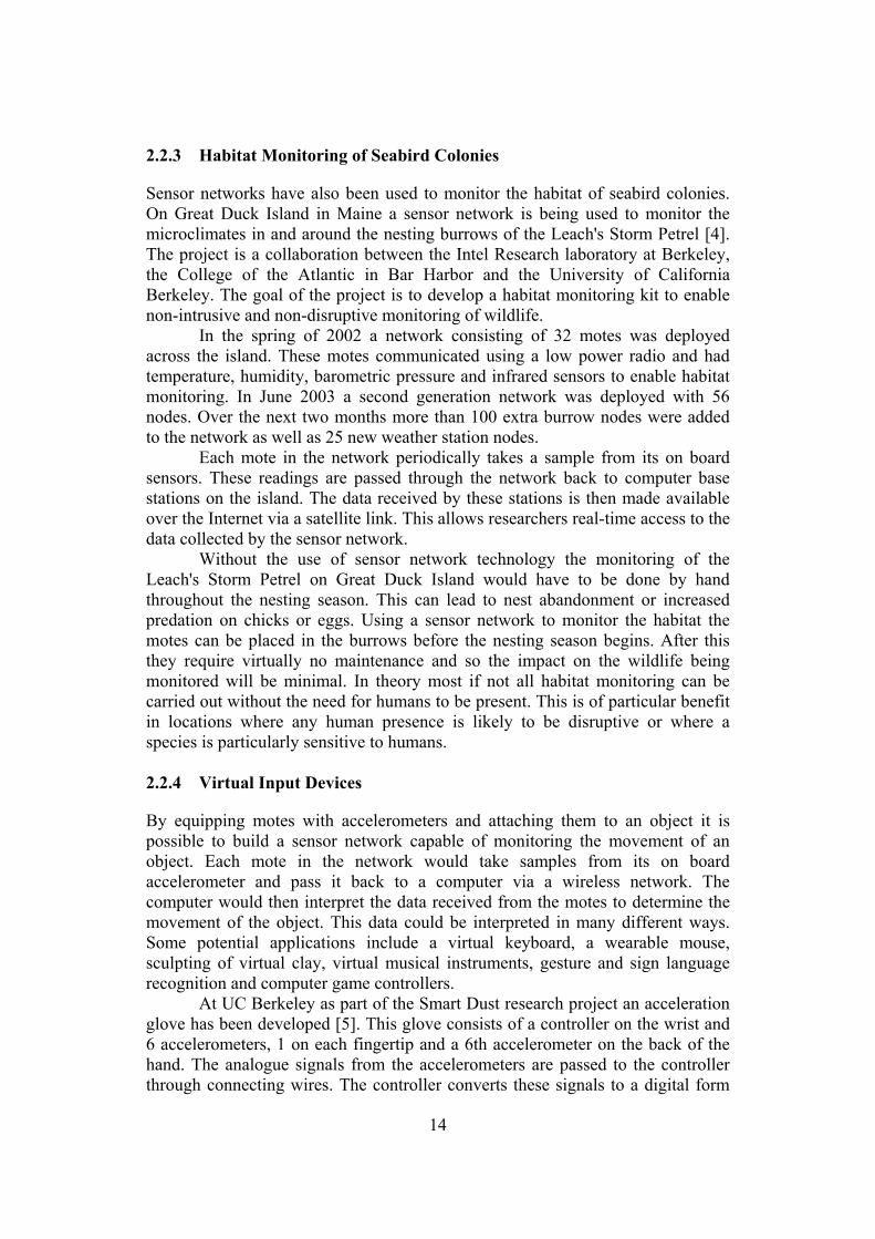
The Mica2 mote [11] is a third generation commercial mote. Like the Mica mote it is produced by Crossbow and used mainly for research and development. The Mica2 mote features several improvements over the original Mica mote. It uses the same processor as the Mica mote as well as the same surface mount 51 pin connector to attach various sensor boards to the mote. The mote also uses the same batteries as the Mica mote and has a similar battery life. However the Mica2 has 512Kbytes of serial flash which is more than the Mica mote. Also the radio transceiver operates on either the 433 MHz band or the 868/916 MHz bands with a data rate of 38.4 Kbps and a maximum outdoor range of roughly 500 feet. Like the Mica mote the Mica2 uses TinyOS in order to control the mote and its attached sensors. The Mica2 also allows every mote to function as a router and supports remote reprogramming over the sensor network.
Figure 2.1: Mica2 mote 2.3.6 Mica2Dot Mote
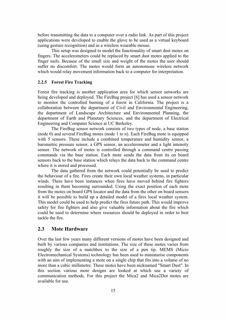
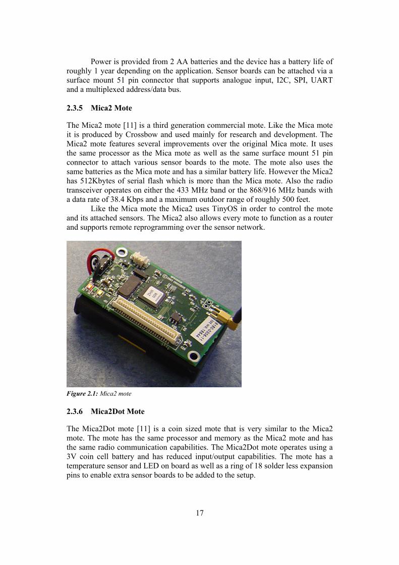
The Mica2Dot mote [11] is a coin sized mote that is very similar to the Mica2 mote. The mote has the same processor and memory as the Mica2 mote and has the same radio communication capabilities. The Mica2Dot mote operates using a 3V coin cell battery and has reduced input/output capabilities. The mote has a temperature sensor and LED on board as well as a ring of 18 solder less expansion pins to enable extra sensor boards to be added to the setup.
18
Figure 2.2: Mica2Dot mote 2.3.7 Spec Mote
Spec [12, 13] was developed by a team or researchers at UC Berkeley and is approximately 2mm2 by 2.5mm2 in size. Spec is a fully working single chip mote which has a RISC core and 3Kbytes of memory. Spec uses radio communication on the 902.4 MHz band. In tests Spec has been shown to communicate over 40ft indoors with a data rate of 19.2 Kbps. 2.3.8 Intel Mote
The aim of Intel's Deep Networking research project [14] was to develop a mote with more CPU power, digital signal processing, a more reliable radio and better security features. The modular design of the original Berkeley motes was maintained whilst Intel worked on improving battery life and reducing costs. In order to achieve this Intel aimed to maintain the operational duty cycle at 1% or less. The Intel mote consists of an ARM processor, SRAM and flash memory. Communication with other motes is via Bluetooth technology with the platform supporting alternative radio technologies as add on modules. Optional sensor boards and an optional power regulator are also available. The Intel mote software is based on TinyOS but has an Intel mote specific layer with added Bluetooth support, platform device drivers and a network layer for topology establishment and also to allow single and multi-hop routing. 2.3.9 Laser Mote
The laser mote [9, 10] uses active laser communication to send sensor data over long distances. The mote runs off 2 AA batteries and contains humidity, light, temperature and pressure sensors. The laser transmitter, a laser module from a laser pointer, needs to be manually pointed towards the receiver. These motes can only send data back to a base station as they have no receiver module on board. These motes have been shown to transmit weather data over a distance of 21 km in the San Francisco Bay area. In this experiment a CCD camera linked to a laptop
19
computer was used as the receiver. However due to the slow speed of the camera data was sent at extremely low data rates but with commercial high speed camera data rates in excess of 1 Kbps are possible. 2.3.10 CCR Mote
The CCR mote [9, 10] was designed at UC Berkeley by Seth Hollar and Farrah Santoso. The mote was equipped with a temperature sensor and uses a corner cube reflector (CCR) module to allow passive laser communication. MEMS technology was used to construct the CCR. In order to communicate first of all an interrogator must project a diverged laser beam in the general direction of the motes. This beam contains commands to be executed by the motes. The motes receive this signal and by modulating and reflecting the beam back to the interrogator the mote can send back data if the command requires it to return data. The communication range is a function of the laser beams intensity. 2.4 TinyOS
TinyOS [16], its libraries and applications are all written in the nesC language which is described in the section on nesC below. TinyOS is an operating system that is designed to manage the operation of a variety of mote devices as well as the sensors attached to them. TinyOS also provides a networking stack to allow the motes to form an ad-hoc network. Since TinyOS has been built using nesC it is built using components and interfaces. This results in a lot of flexibility to select alternative components such as different networking modules that implement different protocols. In order to customise motes for different purposes a single application can be integrated with the TinyOS structure. In many new mote versions the application can be changed remotely over the network after deployment. When TinyOS is compiled all selected components, custom components and the application is integrated into a single multi-threaded program. The TinyOS executable consists of two threads. One thread is used to execute tasks and the other thread is used to execute the hardware event handlers. Tasks are functions which can be deferred. Once they have been scheduled they run to completion without pre-empting each other. Hardware event handlers are called when a hardware interrupt occurs. The hardware event handlers again run to completion but are allowed to pre-empt the execution of a task or another hardware event handler. 2.5 nesC
The nesC language [15] is an extension of the C programming language which was designed to facilitate the implementation of the structuring concepts and execution model of TinyOS. nesC was primarily designed for use with embedded systems such as sensor networks. In nesC there is a separation of construction and composition. Programs are built out of components which are 'wired' together to form whole programs. In nesC components provide and use bidirectional interfaces which are the only way
20
to access a component. An interface declares a set of commands which must be implemented by the interface provider and a set of events which must be implemented by the user of that interface. If a component wishes to call a command in an interface it must implement the events associated with that interface. nesC allows multiple inheritance of interfaces and also allows a component to use multiple instances of the same interface. The nesC language has two types of components, modules and configurations. Modules contain the program code which implements defined interfaces. Configurations are used to connect interfaces used by modules to the interfaces provided by other modules. This is referred to as the wiring between modules. Every application in nesC must have a top level configuration that wires the modules of that application together. Concurrency is supported in nesC in a way which supports the concurrency model of TinyOS. Concurrency in nesC is based on run-to-completion tasks and interrupt handlers. Interrupt handlers may interrupt tasks as well as other interrupt handlers. 2.6 TinyOS Simulator (TOSSIM)
TOSSIM [17] is a discrete event simulator which has been designed to simulate sensor networks that use the TinyOS operating system. The main aim of TOSSIM is to provide a high fidelity simulation of TinyOS applications. In order to achieve this the focus of TOSSIM is to simulate the execution of TinyOS as opposed to simulating the real world. TOSSIM simulates TinyOS' behaviour at a very low level. The network is simulated at the bit level and every system interrupt is captured. Time in TOSSIM is not modelled accurately. While TOSSIM precisely times interrupts it does not attempt to model execution time. In a simulation a piece of code runs instantaneously. A 4 MHz time granularity is used which is the CPU clock speed of the Rene and Mica mote platforms. TOSSIM provides 2 basic radio models. The default "simple" model places every node in a single cell. Packets are transmitted over the radio without error and are received by every node in the network. With this model it is possible (but highly unlikely) that two nodes could transmit a packet at the same time with the result of both packets being corrupted due to the overlap of the signals. The "lossy" model places nodes in a directed graph where an edge (a,b) indicates that a packet sent by node a can be heard by node b. In addition a floating point number between 0 and 1 is assigned to each edge giving the probability of an error occurring on the link. Asymmetric links between nodes can be represented in this model due to the use of directed edges in the connectivity graph. A Java tool is provided with TinyOS to allow loss topologies to be generated. TOSSIM does not model any properties other than those above. In order to allow TOSSIM to be extended a socket based command API is provided. This API allows conditions within the network to be changed while the simulation is running. One tool which uses this API is TinyViz, a Java application which presents a GUI based front end to TOSSIM. Plug-ins can be developed for
21
TinyViz which interact with the simulator. For example plug-ins could include a module for monitoring power usage and an improved radio model. When using TOSSIM to test an application for a sensor network no major work is required to adapt the application to run on the simulator. TOSSIM builds directly from the TinyOS components and requires a TinyOS implementation to be provided in order to be able to run simulations using the application 2.7 Routing in Wireless Sensor Networks
2.7.1 Factors Influencing Protocol Choice
There are several factors which limit what routing protocols can be used in wireless sensor networks. The individual motes within the sensor network have limited resources. These resources include battery power, processing power and memory. The later two factors mean that any protocols employed within the network must not take up too much processor resources and should use as little memory as possible. In order to allow each mote to function for as long as possible the routing protocols employed must also be energy efficient. The topology of a sensor network may also influence protocol choice. This includes the number of nodes and the node density as well as the data movement within the network. For example, networks with a fixed base station receiving data from remote nodes require different protocols from networks where nodes send data to a mobile base station such as in the Pursuit-Evasion Game demonstration. 2.7.2 Flooding
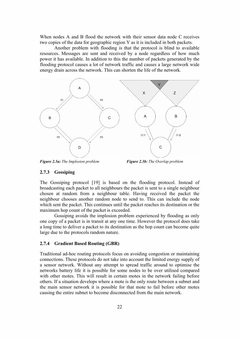
In the flooding protocol [19] each node receiving a data or management packet repeats the packet by broadcasting it. Only packets which are destined for the node itself or packets whose hop count has exceeded a preset limit are not forwarded. The main benefit of flooding is that it requires no costly topology maintenance or route discovery. Once sent a packet will follow all possible routes to its destination. If the network topology changes sent packets will simply follow the new routes added. Flooding does however have several problems. One such problem is implosion. Implosion is where a sensor node receives duplicate packets from its neighbours. Figure 2.3a illustrates the implosion problem. Node A broadcasts a data packet ([A]) which is received by all nodes in range (nodes B and C in this case). These nodes then forward the packet by broadcasting it to all nodes within range (nodes A and D). This results in node D receiving two copies of the packet originally sent by node A. This can result in problems determining if a packet is new or old due to the large volume of duplicate packets generated when flooding. Overlap is another problem which occurs when using flooding. If two nodes share the same observation region both nodes will witness an event at the same time and transmit details of this event. This results in nodes receiving several messages containing the same data from different nodes. Figure 2.3b illustrates the overlap problem. Nodes A and B both monitor geographic region Y.
22
When nodes A and B flood the network with their sensor data node C receives two copies of the data for geographic region Y as it is included in both packets. Another problem with flooding is that the protocol is blind to available resources. Messages are sent and received by a node regardless of how much power it has available. In addition to this the number of packets generated by the flooding protocol causes a lot of network traffic and causes a large network wide energy drain across the network. This can shorten the life of the network.
Figure 2.3a: The Implosion problem Figure 2.3b: The Overlap problem 2.7.3 Gossiping
The Gossiping protocol [19] is based on the flooding protocol. Instead of broadcasting each packet to all neighbours the packet is sent to a single neighbour chosen at random from a neighbour table. Having received the packet the neighbour chooses another random node to send to. This can include the node which sent the packet. This continues until the packet reaches its destination or the maximum hop count of the packet is exceeded. Gossiping avoids the implosion problem experienced by flooding as only one copy of a packet is in transit at any one time. However the protocol does take a long time to deliver a packet to its destination as the hop count can become quite large due to the protocols random nature. 2.7.4 Gradient Based Routing (GBR)
Traditional ad-hoc routing protocols focus on avoiding congestion or maintaining connections. These protocols do not take into account the limited energy supply of a sensor network. Without any attempt to spread traffic around to optimise the networks battery life it is possible for some nodes to be over utilised compared with other motes. This will result in certain motes in the network failing before others. If a situation develops where a mote is the only route between a subnet and the main sensor network it is possible for that mote to fail before other motes causing the entire subnet to become disconnected from the main network.

23
To fully optimise network paths in order to maximise energy efficiency requires future knowledge of all packets that are going to be transmitted. In a real world networking scenario future knowledge is not available. Optimal routing in energy constrained sensor networks is not possible. However it is possible to produce protocols which are energy efficient. One possible solution is to use a form of Gradient Based Routing (GBR) [18]. In its basic form GBR involves recording the minimum number of hops between nodes. Each node in the network can look at its neighbours hop count and use this to decide which node to forward the packet on to. This results in a network where the data is always sent via the optimal path. Also because sensor networks could potentially be made up of many thousands of nodes this scheme is only really suitable for use when each mote needs to communicate with only a small selection of nodes on the network. The basic GBR scheme could be modified to spread the data around the network in a more energy efficient way. The first way is a stochastic scheme. When using a basic GBR protocol if two paths have the same depth (or hop count) the same path is chosen each time. In an effort to spread the load more evenly across the network the stochastic scheme chooses a path at random from the available paths that have the same lowest depth. Another way to improve energy efficiency is to use an energy based scheme. In this scheme nodes are allowed to change their depths depending on their power level. If the nodes power level drops below a certain level it will, under this scheme, increase its depth. This will spread through the network and has the result of discouraging traffic from flowing through that node. Another possible way is to use a stream based scheme. In this scheme new streams are encouraged to take a different path from existing streams. Once a stream has been established nodes through which the stream run increase their depth. The nodes currently sending data through that node won't see the depth increase and so will not be discouraged from using the path. However other nodes see an increased depth and are therefore encouraged to find other routes through the network. 2.7.5 Low-Energy Adaptive Clustering Hierarchy (LEACH)
The LEACH protocol [20] is a dynamic cluster based protocol. The LEACH protocol assumes that the network consists of a remote base station and a set of homogeneous sensor nodes that are energy constrained. All sensor nodes are capable of direct communication with the base station but this is expensive in terms of energy usage. LEACH reduces the number of nodes that communicate directly with the base station by forming clusters. Leaf nodes connect to the cluster head which requires the least amount of power to communicate with. The cluster head nodes connect directly to the base station. Cluster head nodes allocate each leaf node that connects to it a time slot to communicate in. This allows the leaf nodes to sleep between its allocated communication slots. Once the cycle of slots has completed the data from that cycle is aggregated by the cluster head to save power and then it is sent back to the base station.
24
When the cluster heads are fixed the cluster heads are required to do a lot of work which requires a lot of energy. Eventually this would lead to node failure. In order to avoid this LEACH uses rounds. At the beginning of each round each node in the network decides if it should become a cluster head based on a probability factor and whether it has been a cluster head in a previous round. This results in dynamic clusters with each node taking a turn in forwarding packets to the base station. This reduces the energy drain on particular nodes caused by static clusters and spreads energy usage more evenly across the network. 2.7.6 Sensor Protocols for Information via Negotiation (SPIN)
The SPIN [21] family of protocols are an enhancement of the flooding protocol which is based on data-centric routing. Classic flooding as previously mentioned has three problems: implosion, overlap and resource blindness. In order to overcome the problems of implosion and overlap the SPIN family of protocols use a 3 way negotiation before sending data. When a node detects an event it advertises (ADV) the event by transmitting a description of the event. This avoids transmitting the full details of the event. This advertisement is picked up by neighbouring nodes and if they are interested in the data they reply requesting the data (REQ). When the original node receives a request it sends the data to the requesting node. The receiving node will then repeat the process by advertising the data. This prevents nodes from receiving duplicate packets (implosion) as data is only sent when requested. Also as data is described in the advertisement message the problem of overlap can be overcome by checking to see if the node has already received similar data relating to that event. The protocol described above is SPIN-1. SPIN-2 is an extension of SPIN-1 which attempts to overcome the resource blindness problem. Before taking part in the above protocol nodes poll their resources. If their resources fall below a threshold the node will not send or relay data packets. 2.7.7 Directed Diffusion
Directed diffusion [22] works by disseminating sensor tasks throughout the sensor network as an interest for named data. The dissemination of the interest sets up time stamped gradients in the network designed to draw data about events back to the originating node (the sink). When sensors detect events matching the request the event is sent towards the originator along multiple paths. The stored gradients give a direction and data rate and are used to determine the paths to be taken. Initially the sink requests a low data rate from the network. Once the sink begins to receive data back from the network it reinforces one or more paths with a higher data rate. The interest is periodically refreshed with a new time stamp by the sink to keep the interest up to date. 2.7.8 Rumour Routing
Rumour routing [23] is based on events and queries. Nodes maintain a list of events that the node knows about. When a node witnesses an event an entry is placed in the event table with a distance of zero to the event. The node also probabilistically generates an agent according to a specified probability.
25
An agent is a packet which has a long life and carries information about events. The agent carries an event table which it synchronises with every node along its path. After a certain number of hops the agent dies. A straightening algorithm is used to determine the agents path through the network which results in better dissemination of the events in the network. As wireless networks are inherently broadcast the path is thickened by having close by nodes, that are not the intended recipient of the agent, use the data in the agents event table to enhance its own event table. Expiration timestamps can be also used in cases where events are temporary. A query can be generated at any time by any node. Queries are targeted to an event. If the node has a route toward the event it forwards the query along the route. If it does not have a route it forwards the query to a random neighbour assuming that the query has not exceeded its time to live (TTL). Again a straightening algorithm is applied to the route in order to optimise the route chosen. If a query arrives at a node which has already been forwarded the node should send the query to a random neighbour. This compensates for loops brought about by node failure. Query packets also contain a list of recently seen nodes in order to avoid revisiting nodes.

26
3 Specification
3.1 Overview of Requirements
In order to complete the aims and objectives as outlined in the introduction the following are required:
• Implementations of the chosen routing protocols for the TinyOS platform.
• An application program for the TinyOS platform to generate network traffic.
• Time synchronisation between nodes in the network.
• Simulation of the implemented TinyOS components.
3.2 Routing Protocol Specification
The following three protocols were chosen for implementation:
• Flooding
• Gossiping
• And a modified version of LEACH
Flooding is one of the simplest protocols available and is often used as part of other protocols. Flooding was chosen for implementation and evaluation as it provides a base protocol to compare more elaborate protocols against. Gossiping is very similar to flooding but avoids the implosion problem by forwarding packets to a random neighbour. Gossiping was chosen in order to evaluate the improvements it offers over flooding. LEACH was designed to minimise power dissipation across the network and to spread the power usage evenly across the network. This is a desirable property for sensor networks and so a modified version of LEACH was chosen in order to evaluate the benefits of the protocol. 3.2.1 Routing Component Architecture
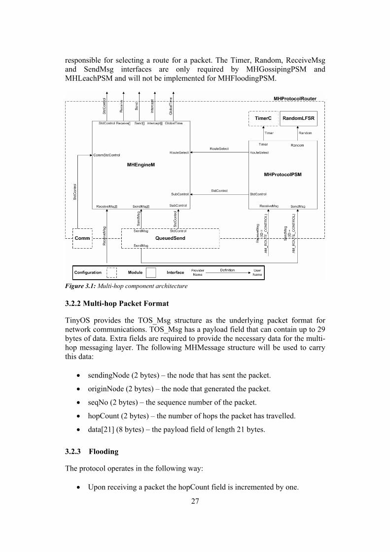
TinyOS includes an optional multi-hop routing layer for applications which require multi-hop functionality. For this dissertation a modified version of the architecture was used which only included the required interfaces. This architecture is shown in figure 3.1.
The MHEngineM component provides the overall packet movement logic for multi-hop routing. MHEngineM provides methods to send and receive packets over the network. It utilises the services of the route selection module to select the next hop for the packet to be sent.
MHProtocolPSM represents three path selection modules. The three components are MHFloodingPSM (Flooding), MHGossipingPSM (Gossiping) and MHLeachPSM (LEACH). These components maintain routing state and are
27
responsible for selecting a route for a packet. The Timer, Random, ReceiveMsg and SendMsg interfaces are only required by MHGossipingPSM and MHLeachPSM and will not be implemented for MHFloodingPSM.
Figure 3.1: Multi-hop component architecture 3.2.2 Multi-hop Packet Format
TinyOS provides the TOS_Msg structure as the underlying packet format for network communications. TOS_Msg has a payload field that can contain up to 29 bytes of data. Extra fields are required to provide the necessary data for the multi-hop messaging layer. The following MHMessage structure will be used to carry this data:
• sendingNode (2 bytes) – the node that has sent the packet.
• originNode (2 bytes) – the node that generated the packet.
• seqNo (2 bytes) – the sequence number of the packet.
• hopCount (2 bytes) – the number of hops the packet has travelled.
• data[21] (8 bytes) – the payload field of length 21 bytes.
3.2.3 Flooding
The protocol operates in the following way:
• Upon receiving a packet the hopCount field is incremented by one.

28
• Each node maintains a list of previously seen packets. This list is of a set size containing the details of the most recently seen packets. A combination of the originNode and seqNo fields is used as a unique identifier of a packet. If the originNode and seqNo fields of a received packet match any of the values in the list the packet will be dropped as a duplicate. This approach is an attempt to limit the implosion problem present when using flooding.
• If the packet is new a sensor node will forward the packet as long as the hopCount field has not reached the maximum value allowed. If the node is the base station the packet is forwarded regardless of its hopCount.
• If the node is the base station the packet will be forwarded to the UART address otherwise the packet will be broadcast to every node within range.
3.2.4 Gossiping
The Gossiping protocol relies on a neighbour table to keep a list of currently alive neighbour nodes. In order to maintain this list each node sends an advertisement packet periodically. The packet has the following structure:
• nodeID (2 bytes) – the address of the node
The protocol operates in the following way:
• Upon receiving a packet the hopCount field is incremented by one.
• If the node is the base station the packet is forwarded to the UART address.
• Other nodes forward the packet to a random neighbour from its neighbour table so long as the maximum hop count for the packet has not been exceeded. If no alive neighbour nodes are listed in the neighbour table the packet is dropped.
Gossiping does not require the use of a sequence number as only one copy of each packet will ever be in transit at any one time. 3.2.5 Modified LEACH
In the LEACH protocol described in section 2.7.5 cluster heads communicate directly with a remote base station. The Mica2 and Mica2Dot motes are incapable of supporting this as transmission range is very limited. The version of the LEACH protocol presented here is an attempt to overcome this problem. Cluster heads form a tree which has the base station at the root. Leaf nodes connect to the base station through a chosen cluster head. Like the original version of LEACH the operation of the protocol is split into distinct rounds. At the beginning of the round each node decides if it is to become a cluster head based on a fixed probability. The base station is always a cluster head and is responsible for initiating new rounds.

29
In order to maintain neighbour tables that are necessary for parent selection and to synchronise rounds each node must advertise its presence periodically. The following fields are used as part of a packet to transmit this information:
• addr (2 bytes) – address of node that is to become a cluster head.
• nodeID (2 bytes) – address of sending node.
• depth (2 bytes) – depth of sending node in the tree.
• round (1 byte) – current round according to sending node.
• isClusterHead (Boolean) – cluster head status of sending node.
• becomeClusterHead (Boolean) – indicates if the receiving node should become a cluster head.
Rounds are signalled in the protocol in the following way:
• Periodically the base station starts a new round by incrementing the round number.
• Gradually the new round is signalled to all nodes in the network by using the round field in the advertisement packet.
• When a node detects a new round it resets its neighbour table and decides whether to become a cluster head or leaf node for the next round.
During a round nodes in the network select a parent node periodically. The base station always has the UART address as its parent. Other nodes however choose its parent node based on neighbouring cluster heads depth in the tree. As it is possible for nodes to remain disconnected from the network due to a cluster head not being in range each node is able to request that another connected node become a cluster head. This occurs after a timeout period and is done through a normal advertisement message. The address of the node to become a cluster head is carried in the addr field. Packet transport under the protocol works as follows:
• Only cluster head nodes can forward packets for other nodes.
• Leaf nodes send newly generated packets to their parent nodes. If a valid parent is not available the packet is dropped.
• Cluster head nodes forward packets to their parent nodes. If a valid parent is not available the packet is dropped.
3.3 Application Program Specification
In order to gather data about the operation of the chosen routing protocols during simulation network traffic is required. In order to generate this traffic a simple

30
application is required which transmits data periodically using the multi-hop messaging services provided. The application chosen is a simple temperature monitor. The application periodically takes a temperature reading from a thermometer attached to the motes. This reading is then time stamped and sent to the base station using the multi-hop routing layer. The data is carried in an application packet which has the following format:
• address (2 bytes) – the address of the origin node.
• timestamp (4 bytes) – the time at which the packet was sent.
• reading (2 bytes) – the sensor reading.
3.4 Time Synchronisation
In order to measure the time taken for a packet to traverse the network some form of time synchronisation is required between all nodes in the network. TinyOS includes several contributed time synchronisation components such as the components provided by Vanderbilt University. These will be looked at in order to find a suitable implementation for integration with the system to be developed. 3.5 Protocol Simulation Specification
3.5.1 Chosen Simulator
In order to evaluate the protocols TOSSIM will be used. TOSSIM is provided free with TinyOS. It is designed to emulate a sensor network running TinyOS on a PC. In theory this should mean that code developed for the hardware will also work on the simulator without modification. 3.5.2 Metrics
The following metrics will be used when evaluating the protocols:
• Latency – The time taken to deliver a packet to the base station from the origin node will be looked at when evaluating the protocols. In addition the per hop time delay will also be looked at. Lower latency is preferable to higher latency.
• Battery usage – The amount of power used during the simulation will be monitored and used for evaluating the protocols. Batteries have a finite amount of power and nodes die once power runs out. For this reason lower power usage is preferable to higher power usage. In addition the distribution of power usage across the network will be looked at. Uniform drain is preferable.
• Loss of data – The number of packets received from a node at the base station will be compared with the number of packets sent by a node in

31
order to calculate the number of packets lost. A low packet loss rate is preferable to a high packet loss rate.
• Connectivity – The number of nodes that have a route to the base station will be used to assess the node connectivity provided by a particular routing protocol. More connected nodes in a network are preferable to fewer connected nodes.
32
4 Protocol Implementation
4.1 Component Overview
The following components were modified or created during implementation:
• TimeSyncM – This module provides a basic time synchronisation service for the network. Nodes synchronise to a network global time which is based on the local time of node 0.
• MHEngineM – This module is a modified version of MultiHopEngineM from the TinyOS multi-hop routing component library. This module is the main component of the multi-hop messaging layer and provides the packet movement logic.
• MHFloodingPSM - This module provides the route selection logic for the flooding protocol.
• MHGossipingPSM – This module provides the route selection logic for the gossiping protocol.
• MHLeachPSM – This module provides the route selection logic for the modified LEACH protocol.
• TempMonM – This module provides network traffic by sending packets containing sensor data periodically.
The nesC source code for all modules, configurations and interfaces can be found in Appendix A. 4.2 Time Synchronisation (TimeSyncM)
4.2.1 Initial Attempts
At first the aim was to use existing time synchronisation components for TinyOS. The contrib branch of the TinyOS tree contains a time synchronisation library that has been developed by Vanderbilt University [24]. When using this component all nodes in the network run the same algorithm, choosing a root of the network in the beginning. The root of the network maintains the global time with the rest of the nodes synchronising their clocks to this global time. Time synchronisation messages are sent periodically by each node in order to stay synchronised. Each node uses a certain number of previous messages to calculate the skew and offset of its local time compared to the global time. Unfortunately it was not possible to use this component for this dissertation. The library uses a custom high precision clock which does not currently have an implementation for TOSSIM.
33
4.2.2 Implementation of TimeSyncM
After failing to find an existing time synchronisation library which would work with TOSSIM a simple component was built to provide a limited time synchronisation service. Like the components produced by Vanderbilt University the implemented component uses the local time of a root node as the global time of the network. It was decided to use the local time of node 0 (the base station) as the global time of the network. The base station is automatically synchronised to global time with an offset of 0. Each node in the network once synchronised to global time, periodically broadcasts the global time as known by that node. Upon receiving a time synchronisation packet the receiving node adds a hop delay to the advertised time and treats this as the current global time. The hop delay is an algorithmic parameter which requires calibration. The difference between the nodes current local time and the received global time is calculated and stored as the offset of global time compared to local time. Once an offset has been calculated the node is considered to be synchronised to global time. The implemented time synchronisation module provides the GlobalTime interface which consists of two commands. The first command, isSynchronised, returns a Boolean value which indicates if the node is synchronised to global time. The second command, getGlobalTime, returns the current global time as known by the node in the form of an unsigned 32 bit integer. 4.3 Routing Components
4.3.1 Multi-hop Engine (MHEngineM)
The MHEngineM component implemented during this project is a modified version of the MultiHopEngineM component which is part of the standard TinyOS multi-hop routing library. A substantial amount of code was added to the original module to collect data about the operation of the multi-hop subsystem during a simulator run. As the code is designed only to be used when simulating the operation of the protocols the modifications are discussed in the next chapter. These modifications do not affect the packet movement logic provided by this module and are only included in the binary when SIM has been defined through the PFLAGS environment variable. Other than the above modifications the only other changes to the module was to use the GenericComm component rather than the GenericCommPromiscuous component and the removal of interfaces which weren’t required by the implemented protocols. The removed interfaces are Snoop, RouteControl and CommControl. The MHEngineM component provides the Send interface to the higher layers in the networking stack and uses the ReceiveMsg and SendMsg interfaces of lower networking layers to send and receive data itself. The RouteSelect interface is used to communicate with the path selection modules whose implementations are discussed below.
34
4.3.2 Flooding Protocol Path Selection Module (MHFloodingPSM)
MHFloodingPSM is the path selection module for the flooding protocol. It is responsible for providing the MHEngineM module with a route decision via the RouteSelect interface. When using the flooding protocol packets are sent to every node within range by addressing all packets to the broadcast address. The base station does not flood packets but instead addresses packets to the UART address. By choosing the next hop address in this way a valid route will always be available and so all packets passed to the module via the RouteSelect interface are provided with a route as long as the packet has not been forwarded by the node previously. A packet will also be dropped if the maximum hop count of the packet has been exceeded if the packet is to be flooded. In order to detect previously received packets a log is kept containing details about a set number of previously seen packets. Due to its limited size the log does not guarantee to detect all duplicate packets received. It does however limit the implosion problem which is present when using flooding. All packets sent using the flooding protocol are allocated a sequence number before being sent. A getSeqNo method is provided which returns the next sequence number to be used. The sequence numbers range from 0 to 29999 which provides a large enough sequence number space to prevent two unique packets from the same node carrying the same sequence number in a network at any one time. By combining a packets sequence number with the id of its originator node each unique packet has a unique identifier. When a node is successfully allocated a route by the module the packet sequence number and the node id of the origin node are stored in the previous packet log overwriting the oldest packet if there is no space available for a new entry. The addLogEntry method is provided which takes a node id and sequence number and adds a packets details to the log. Another method inLog is provided which takes a packets sequence number and origin id and checks if the packet has been recorded in the log previously. As mentioned previously MHEngineM uses this module to select a route via the RouteSelect interface. This interface requires three commands to be implemented. The first isActive returns a Boolean value indicating whether a valid route exists or not. As the flooding protocol always has a valid route this module simply returns true. The initializeFields command takes a packet and sets the fields to indicate that the packet is from this node. In order to do this it sets the origin node and sending node address fields to be the local node id and sets the packets hop count to be 0. The selectRoute command is used to select a route for a packet. If the packet is a new packet being sent from the node it is allocated a sequence number. Otherwise the hop count is incremented and the sending node field set to indicate that the current node is sending the packet. The packet is dropped if it is found in the previous packet log. Next the packets address field is set to indicate the next hop address. If the node is the base station it is set to the UART address otherwise it is set to the broadcast address. Finally for packets being sent to the broadcast address a check is made to make sure that the maximum hop count has not been
35
exceeded. If it has the packet is dropped. Otherwise a route has successfully been selected and success is indicated. 4.3.3 Gossiping Protocol Path Selection Module (MHGossipingPSM)
MHGossipingPSM is the path selection module for the gossiping protocol. It is responsible for providing the MHEngineM module with a route decision via the RouteSelect interface. When using the gossiping protocol packets are forwarded to a random neighbouring node or the UART address if the node is the base station. Packets are forwarded as long as the maximum hop count has not been exceeded. Sequence numbers and a previous packet log are not required by this protocol as only one copy of a packet will be in transit at any one time. Also it is possible for a packet to visit a node more than once due to the random path taken through the network. Therefore it is important that previously received packets are not dropped by the protocol. In order to send packets to random neighbours each node must maintain a neighbour table. The following details are stored in the neighbour table about each neighbouring node:
• The node id
• The number of packets received from the node
• The number of timer ticks since a packet was received from the node
• Whether the node is alive
• The strength of the link
Each node sets a timer to signal an event periodically. When this event occurs the node advertises its presence by sending just its node id. The advertise task has been provided to carry this out. The updateTable method is also executed which increments the number of timer ticks since a packet was received from a node and sets a nodes alive status to false if the number of timer ticks has exceeded a maximum value.
When a route update packet is received from another node the receive event of the ReceiveMsg interface is signalled. This calls the updateTableEntry method passing the node id and strength of the received packet to the method.
The updateTableEntry method searches the neighbour table for an entry corresponding to the node id passed to it. It also looks for the first dead node in the table and the node which has the lowest link strength whilst navigating the table. If the node id is in the table the method simply updates the entry setting the timer ticks to 0 and the alive status to true. The number of packets received is incremented and the strength is updated. If an entry does not exist in the table the following steps are taken:
• If a dead node was found in the table the entry corresponding to that node
is replaced with an entry for the new node.
36
• Otherwise if the number of entries in the table is less than the maximum number of entries the table can hold a new entry is added.
• Otherwise if the strength of the received packet is greater than the lowest strength in the table the entry corresponding to the lowest strength is replaced with an entry for the new node.
When adding a new entry to the table all the fields corresponding to that entry are set. The node id field is set to the node id of the new node being added. The received count field is reset to 1 and the number of timer ticks since the last packet was received is set to 0. The alive status is also set to true to indicate that the node is alive.
Like MHFloodingPSM the MHGossipingPSM provides the RouteSelect interface. The isActive command returns true if the neighbour table contains a single entry which is alive. The initilizeFields command works in exactly the same way as in the MHFloodingPSM module. The selectRoute command works in the following way. When supplied with a packet to address it first checks if the packet has arrived from another node. If it has it sets the sending node address to the local address and increments the hop count. Next if the node is the base station the node is addressed to the UART address. Otherwise a random node is chosen from the neighbour table as the address of the next hop. If no alive neighbours are available the packet is dropped. Finally the packet is dropped if the hop count has exceeded the maximum hop count allowed unless it is to be forwarded via the UART. 4.3.4 Modified LEACH Protocol Path Selection Module (MHLeachPSM)
MHLeachPSM is the path selection module for the modified LEACH protocol. It is responsible for providing the MHEngineM module with a route decision via the RouteSelect interface. As described in the specification section the LEACH protocol operates using rounds. At the start of each round each node in the network probabilistically decides if it is to become a cluster head for the next round. The base station node is automatically a cluster head. The protocol then forms a tree of cluster heads rooted at the base station in order to forward packets to the base station. Only cluster heads are allowed to forward packets. All nodes in the network have a parent address to which it sends packets to be forwarded. For the base station this address is the UART address. Other nodes choose the neighbouring cluster head with the lowest depth as its parent. Because the location of cluster head nodes varies across the network it is possible that some leaf nodes may not be in range of a cluster head. To get around this problem the protocol allows a leaf node to request that another leaf node become a cluster head after a certain timeout period. The base station uses a timer to control rounds. When the timer fires the base station uses the nextRound method to begin the next round. The new round number is then included in all outgoing route update packets. As nodes receive these route update packets they become aware of the new round and start to include the new round number in all their outgoing route update packets. This
37
continues and so the new round number is gradually propagated throughout the network. When the nodes in the network receive a route update message the receive event of the ReceiveMsg interface is signalled. If the packets round field is set to invalid the packet is ignored. Otherwise the isNewRound method is called to check to see if the round indicated by the packet is new. If it is a new round the startNewRound method is called. This method determines if the node becomes a cluster head, resets the neighbour table, changes the parent to invalid and the depth to infinity. Next the address field of the packet is looked at. If the nodes local address is given the node sets its cluster head status to be the same as the becomeClusterHead field in the route update packet. Finally the node id, depth, cluster head status and strength fields of the packet are passed to updateTableEntry to allow the neighbour table to be updated. The updateTableEntry searches the neighbour table for an entry corresponding to the given node id. At the same time it looks for the first dead node and also the leaf node and cluster head nodes in the table which have the highest depth in the tree. If the given node id corresponds to an existing entry in the table that entry is updated with the nodes current cluster head status, depth and strength. The timer ticks value is set to 0 and the entries alive status is set to true. If the node id does not correspond to an entry in the neighbour table the following occurs:
• If a dead node was found in the table the entry corresponding to that node is replaced with an entry for the new node.
• Otherwise if the number of entries in the table is less than the maximum number of entries the table can hold a new entry is added.
• Otherwise if the new node is a cluster head the leaf node of lowest strength is replaced with the new node if there are any leaf nodes in the table.
• Otherwise if the new node is a leaf node and the strength of the received packet is greater than the lowest strength leaf node value in the table the entry corresponding to the lowest strength leaf node is replaced with an entry for the new node if there are any leaf nodes in the table.
• Otherwise if the new node is a cluster head node and the strength of the received packet is greater than the lowest strength cluster head node value in the table the entry corresponding to the lowest strength cluster head node is replaced with an entry for the new node.
When adding a new entry to the table all the fields corresponding to that entry are set. The node id field is set to the node id of the new node added. The nodes cluster head status and depth are recorded and so is the strength of the link. The timer ticks value is reset to 0 and the entries alive status is set to true.
Every node in the network uses a timer which is used for route maintenance. Every time the timer event fires the updateTable and selectParent methods are called if the current round known by that node is valid. An advertise task is also posted to send a route information packet to indicate its status.
38
The updateTable method increments the timer tick value for each entry in the neighbour table. If the number of ticks has reached the maximum allowed the entries alive status is changed to false.
The selectParent method searches the neighbour table for the cluster head of lowest depth and sets this node to be the parent. If a connected cluster head cannot be found a timer tick is incremented. Once the timer tick for this method reaches a maximum value the method looks for a connected leaf node. If one is found an address variable is set and the node is asked to become a cluster head by the next route update packet. The timer tick value is reset to 0 every time a parent node is selected or a leaf node is chosen to become a cluster head.
The RouteSelect interface is also provided by this module. The isActive command returns true if the parent is valid and the initilizeFields command works in exactly the same was as for the MHFloodingPSM and MHGossipingPSM modules.
The selectRoute command addresses the packet to its parent node as long as a valid parent exists. If the packet was not generated by the local node the sending node field is set and the hop count incremented. The packet is only forwarded if the node is a cluster head. 4.4 Driver Application (TempMonM)
In order to generate network traffic a simple application was required. The application that was developed uses a timer to periodically request data from the temperature sensor and send the current reading over the network.
When the timer fires a call is made to the getData command of the ADC interface. Then if the node is synchronised to global time a sendData task is posted. In order to correctly calculate the transit time for the packet it is essential that the node is synchronised to global time.
When data is ready from the temperature sensor the ADC interfaces dataReady event is signalled. The new sensor reading is copied to a variable which holds the last reading.
The sendData task sends a packet containing the last sensor reading and a timestamp which gives the global time as known by the node when the packet was sent. 4.5 Testing
4.5.1 Testing of TimeSyncM
In order to determine that the time synchronisation components were working correctly temporary debug statements were added to the receive method in the source code. These debug statements print out the global time contained in the incoming time synchronisation packet (with the hop delay added), the current local time and the calculated offset between local time and the received global time. Debug statements were also added to the getGlobalTime method in order to check that the global time was being calculated correctly. When the module was tested in TOSSIM the output showed that the offset was being calculated correctly. However through using the time synchronisation
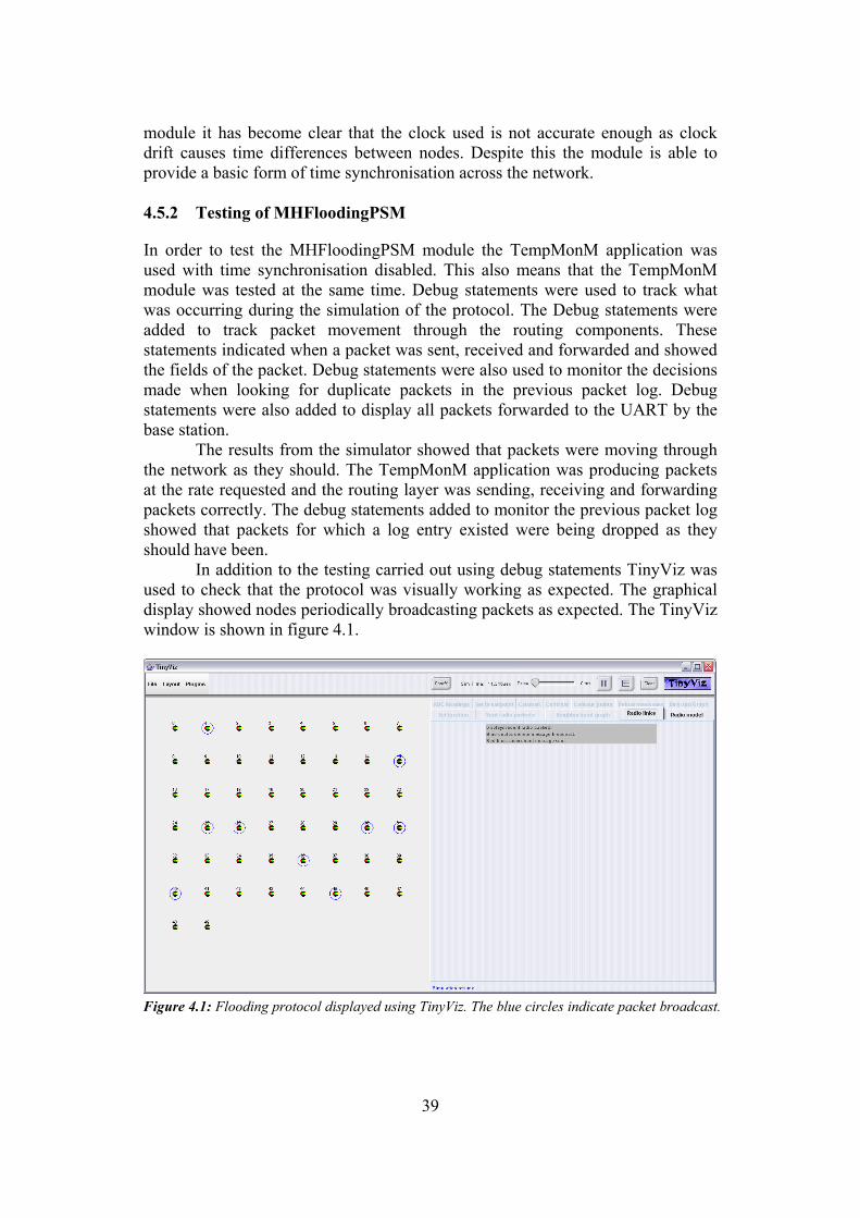
39
module it has become clear that the clock used is not accurate enough as clock drift causes time differences between nodes. Despite this the module is able to provide a basic form of time synchronisation across the network. 4.5.2 Testing of MHFloodingPSM
In order to test the MHFloodingPSM module the TempMonM application was used with time synchronisation disabled. This also means that the TempMonM module was tested at the same time. Debug statements were used to track what was occurring during the simulation of the protocol. The Debug statements were added to track packet movement through the routing components. These statements indicated when a packet was sent, received and forwarded and showed the fields of the packet. Debug statements were also used to monitor the decisions made when looking for duplicate packets in the previous packet log. Debug statements were also added to display all packets forwarded to the UART by the base station. The results from the simulator showed that packets were moving through the network as they should. The TempMonM application was producing packets at the rate requested and the routing layer was sending, receiving and forwarding packets correctly. The debug statements added to monitor the previous packet log showed that packets for which a log entry existed were being dropped as they should have been. In addition to the testing carried out using debug statements TinyViz was used to check that the protocol was visually working as expected. The graphical display showed nodes periodically broadcasting packets as expected. The TinyViz window is shown in figure 4.1.
Figure 4.1: Flooding protocol displayed using TinyViz. The blue circles indicate packet broadcast.
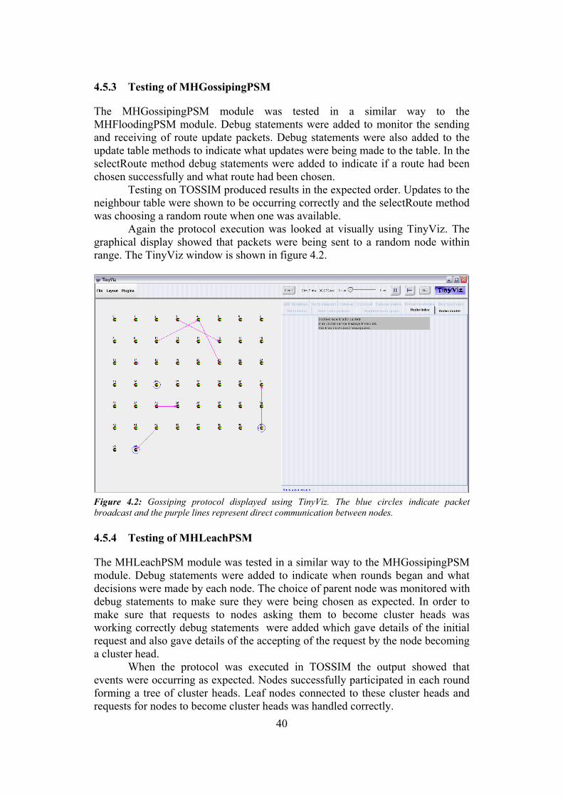
40
4.5.3 Testing of MHGossipingPSM
The MHGossipingPSM module was tested in a similar way to the MHFloodingPSM module. Debug statements were added to monitor the sending and receiving of route update packets. Debug statements were also added to the update table methods to indicate what updates were being made to the table. In the selectRoute method debug statements were added to indicate if a route had been chosen successfully and what route had been chosen.
Testing on TOSSIM produced results in the expected order. Updates to the neighbour table were shown to be occurring correctly and the selectRoute method was choosing a random route when one was available. Again the protocol execution was looked at visually using TinyViz. The graphical display showed that packets were being sent to a random node within range. The TinyViz window is shown in figure 4.2.
Figure 4.2: Gossiping protocol displayed using TinyViz. The blue circles indicate packet broadcast and the purple lines represent direct communication between nodes. 4.5.4 Testing of MHLeachPSM
The MHLeachPSM module was tested in a similar way to the MHGossipingPSM module. Debug statements were added to indicate when rounds began and what decisions were made by each node. The choice of parent node was monitored with debug statements to make sure they were being chosen as expected. In order to make sure that requests to nodes asking them to become cluster heads was working correctly debug statements were added which gave details of the initial request and also gave details of the accepting of the request by the node becoming a cluster head. When the protocol was executed in TOSSIM the output showed that events were occurring as expected. Nodes successfully participated in each round forming a tree of cluster heads. Leaf nodes connected to these cluster heads and requests for nodes to become cluster heads was handled correctly.
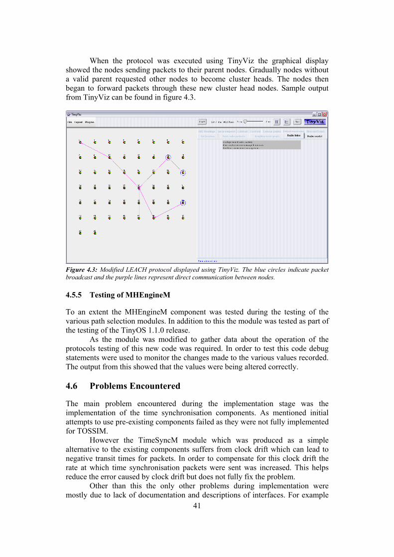
41
When the protocol was executed using TinyViz the graphical display showed the nodes sending packets to their parent nodes. Gradually nodes without a valid parent requested other nodes to become cluster heads. The nodes then began to forward packets through these new cluster head nodes. Sample output from TinyViz can be found in figure 4.3.
Figure 4.3: Modified LEACH protocol displayed using TinyViz. The blue circles indicate packet broadcast and the purple lines represent direct communication between nodes. 4.5.5 Testing of MHEngineM
To an extent the MHEngineM component was tested during the testing of the various path selection modules. In addition to this the module was tested as part of the testing of the TinyOS 1.1.0 release. As the module was modified to gather data about the operation of the protocols testing of this new code was required. In order to test this code debug statements were used to monitor the changes made to the various values recorded. The output from this showed that the values were being altered correctly. 4.6 Problems Encountered
The main problem encountered during the implementation stage was the implementation of the time synchronisation components. As mentioned initial attempts to use pre-existing components failed as they were not fully implemented for TOSSIM. However the TimeSyncM module which was produced as a simple alternative to the existing components suffers from clock drift which can lead to negative transit times for packets. In order to compensate for this clock drift the rate at which time synchronisation packets were sent was increased. This helps reduce the error caused by clock drift but does not fully fix the problem. Other than this the only other problems during implementation were mostly due to lack of documentation and descriptions of interfaces. For example

42
SysTimeC was used initially as the system clock. It was later discovered that this module used ¼ microseconds as the unit of time which caused the clock to revert to zero after approximately 20 minutes. This was not documented and caused problems when timing packet transit through the network.

43
5 Simulation
5.1 Time Synchronisation Calibration
In order to calibrate the per hop delay for the time synchronisation component the TimeSyncTestM module was developed. This module works by repeatedly passing a packet between nodes 0 and 1 in the network. The packet originates at node 0 and travels between the two nodes until it is received at node 0 with a hop count greater than or equal to 100. A debug statement is then used to output the total time taken as well as the total number of hops. The program then repeats the above algorithm until interrupted. The module is only suitable for calculating per hop delay on the simulator as the packet is not forwarded to a computer via the UART. The output from the module was then analysed using a spreadsheet package. It was found that the average delay per hop was 22ms. This was then used as the hop delay parameter for the TimeSyncM component. It is worth noting that this is a rough estimate of the delay as the TimeSyncTestM module does not take network load and other factors into account. 5.2 Modifications Made to MHEngineM
In order to evaluate the protocols with respect to the metrics given in the specification it was necessary to record some values to describe the operation of the protocols. Each node has three variables to allow it to keep track of the number of packets sent, received and forwarded by that node. In addition a fourth variable was introduced to track power usage. The hardware documentation indicates that transmission of a packet requires roughly 1/3 more power than required to receive a packet. Constants were defined to account for this. Receiving was considered to use 2 power units where as transmission was considered to use 3 units. Every time a packet was transmitted 3 units was added to the used power count and every time a packet was received 2 units was added to the count. The power usage figure does not take into account route maintenance packets and time synchronisation packets. In order to track the number of packets sent, forwarded and received by a node code was added to relevant methods to increment the corresponding variable every time a packet was sent, forwarded or received. Note that the number of packets sent refers to the number of packets generated by the local node which were then sent. It was also necessary to track the number of packets received from each node by the base station as well as the time taken for packets to reach the base station from those nodes. In order to do that a SimulationStats type was defined to record the following:
• Number of packets received.
• Total time taken for packets to travel from origin to base station.
• Total time taken per hop by the packets.
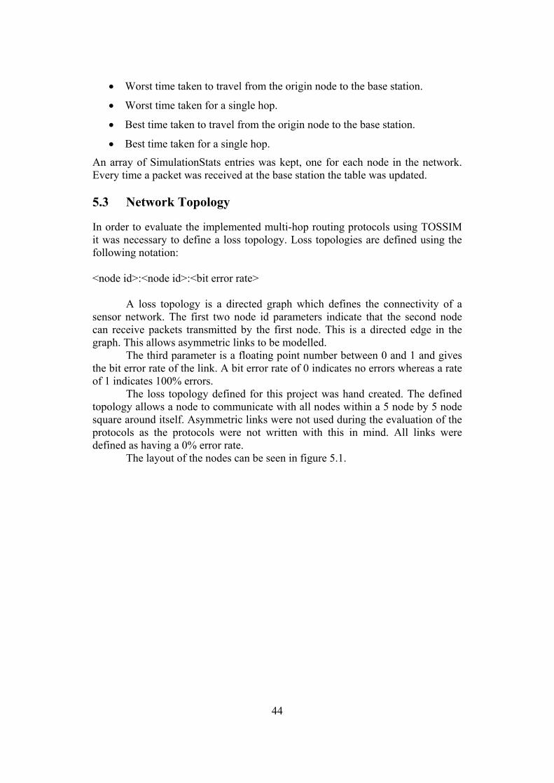
44
• Worst time taken to travel from the origin node to the base station.
• Worst time taken for a single hop.
• Best time taken to travel from the origin node to the base station.
• Best time taken for a single hop.
An array of SimulationStats entries was kept, one for each node in the network. Every time a packet was received at the base station the table was updated. 5.3 Network Topology
In order to evaluate the implemented multi-hop routing protocols using TOSSIM it was necessary to define a loss topology. Loss topologies are defined using the following notation: <node id>:<node id>:<bit error rate> A loss topology is a directed graph which defines the connectivity of a sensor network. The first two node id parameters indicate that the second node can receive packets transmitted by the first node. This is a directed edge in the graph. This allows asymmetric links to be modelled. The third parameter is a floating point number between 0 and 1 and gives the bit error rate of the link. A bit error rate of 0 indicates no errors whereas a rate of 1 indicates 100% errors. The loss topology defined for this project was hand created. The defined topology allows a node to communicate with all nodes within a 5 node by 5 node square around itself. Asymmetric links were not used during the evaluation of the protocols as the protocols were not written with this in mind. All links were defined as having a 0% error rate. The layout of the nodes can be seen in figure 5.1.
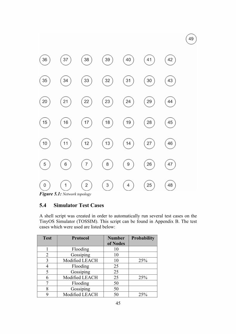
45
Figure 5.1: Network topology 5.4 Simulator Test Cases
A shell script was created in order to automatically run several test cases on the TinyOS Simulator (TOSSIM). This script can be found in Appendix B. The test cases which were used are listed below:
Test Protocol Number of Nodes
Probability
1 Flooding 10 2 Gossiping 10 3 Modified LEACH 10 25% 4 Flooding 25 5 Gossiping 25 6 Modified LEACH 25 25% 7 Flooding 50 8 Gossiping 50 9 Modified LEACH 50 25%
46
Test Protocol Number of Nodes
Probability
10 Modified LEACH 50 10% 11 Modified LEACH 50 50%
Each protocol was simulated with 10, 25 and 50 nodes in order to see what effect the size of the network has on the operation of the protocol. In addition to these tests the final three test cases look at the operation of the LEACH protocol for a network of 50 nodes with varying probabilities to see what affect the probability used has on the operation of the protocol. 5.5 Problems Encountered
Several problems were encountered during the simulation stage of the dissertation. Initially it was hoped to use TinyViz to gather data on how well the protocols worked under certain conditions. The first problem encountered when using TinyViz was the program freezing up during the simulation. This occurred when simulating any part of the implemented code and even occurs when using TinyViz to simulate the operation of applications which come with TinyOS and have been thoroughly tested. Eventually it was discovered that the problem was down to the debug statement output. Depending on what debugging output was chosen the amount of debugging output can become extremely large. TinyViz can not handle the volume of data output and freezes up. By limiting the debugging output this problem was solved. It was hoped that the auto run feature of TinyViz could be used to script simulation runs. However auto run would not work on any computer used during the dissertation. According to articles on the TinyOS mailing lists the problem is due to the TinyViz application changing the path at runtime which results in the system being unable to locate required components. No solution to this problem was found. It was eventually decided to use the command line TOSSIM interface for simulation. This provided all the output needed and also had the advantage of speeding up simulation due to the lack of a complex interface to manage. In order to model multi-hop networks using the command line simulator it was necessary to generate a loss topology. Initially an attempt was made to use LossyBuilder to generate a topology. LossyBuilder is a java tool which takes a list of node coordinates and generates a loss topology based on empirical data gathered by UC Berkeley. It is part of the net.tinyos.sim package which is provided with TinyOS. Unfortunately a documented bug in LossyBuilder resulted in more links between nodes being created than there should have been. After many attempts to generate a loss topology using LossyBuilder it was decided to write a loss topology from scratch. This loss topology was used with the simulator without any problems. 5.6 Results
The output from the simulator can be found in Appendix B. This output has been formatted using a spreadsheet package for readability. In order to evaluate the
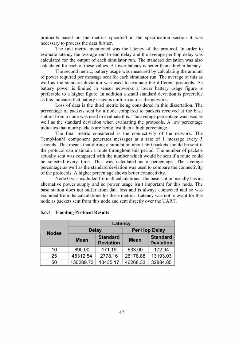
47
protocols based on the metrics specified in the specification section it was necessary to process the data further. The first metric mentioned was the latency of the protocol. In order to evaluate latency the average end to end delay and the average per hop delay was calculated for the output of each simulator run. The standard deviation was also calculated for each of these values. A lower latency is better than a higher latency. The second metric, battery usage was measured by calculating the amount of power required per message sent for each simulator run. The average of this as well as the standard deviation was used to evaluate the different protocols. As battery power is limited in sensor networks a lower battery usage figure is preferable to a higher figure. In addition a small standard deviation is preferable as this indicates that battery usage is uniform across the network. Loss of data is the third metric being considered in this dissertation. The percentage of packets sent by a node compared to packets received at the base station from a node was used to evaluate this. The average percentage was used as well as the standard deviation when evaluating the protocols. A low percentage indicates that more packets are being lost than a high percentage. The final metric considered is the connectivity of the network. The TempMonM component generates messages at a rate of 1 message every 5 seconds. This means that during a simulation about 360 packets should be sent if the protocol can maintain a route throughout this period. The number of packets actually sent was compared with the number which would be sent if a route could be selected every time. This was calculated as a percentage. The average percentage as well as the standard deviation was used to compare the connectivity of the protocols. A higher percentage shows better connectivity. Node 0 was excluded from all calculations. The base station usually has an alternative power supply and so power usage isn’t important for this node. The base station does not suffer from data loss and is always connected and so was excluded from the calculations for these metrics. Latency was not relevant for this node as packets sent from this node and sent directly over the UART. 5.6.1 Flooding Protocol Results
Latency Delay Per Hop Delay Nodes
Mean Standard Deviation Mean Standard
Deviation 10 890.00 171.19 633.00 172.94 25 45312.54 2778.16 26178.88 13193.03 50 130289.73 13435.17 46268.33 32884.85
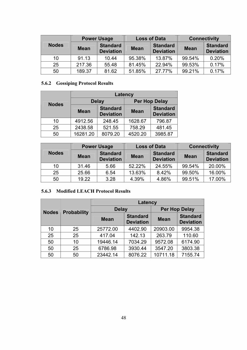
48
Power Usage Loss of Data Connectivity Nodes Mean Standard
Deviation Mean Standard Deviation Mean Standard
Deviation10 91.13 10.44 95.38% 13.87% 99.54% 0.20% 25 217.36 55.48 81.45% 22.94% 99.53% 0.17% 50 189.37 81.62 51.85% 27.77% 99.21% 0.17%
5.6.2 Gossiping Protocol Results
Latency Delay Per Hop Delay Nodes
Mean Standard Deviation Mean Standard
Deviation 10 4912.56 248.45 1628.67 796.87 25 2438.58 521.55 758.29 481.45 50 16281.20 8079.20 4520.20 3985.87
Power Usage Loss of Data Connectivity
Nodes Mean Standard Deviation Mean Standard
Deviation Mean Standard Deviation
10 31.46 5.66 52.22% 24.55% 99.54% 20.00% 25 25.66 6.54 13.63% 8.42% 99.50% 16.00% 50 19.22 3.28 4.39% 4.86% 99.51% 17.00%
5.6.3 Modified LEACH Protocol Results
Latency Delay Per Hop Delay Nodes Probability
Mean Standard Deviation Mean Standard
Deviation 10 25 25772.00 4402.90 20903.00 9954.38 25 25 417.04 142.13 263.79 110.60 50 10 19446.14 7034.29 9572.08 6174.90 50 25 6786.98 3930.44 3547.20 3803.38 50 50 23442.14 8076.22 10711.18 7155.74
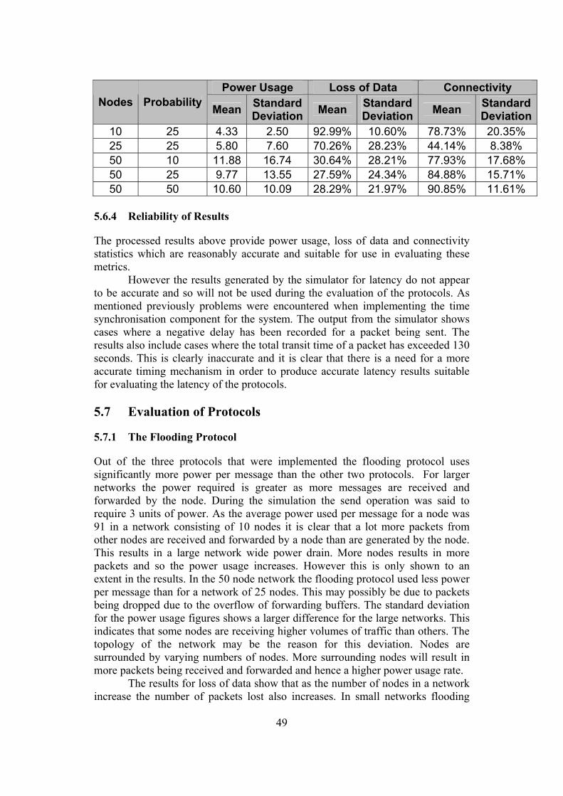
49
Power Usage Loss of Data Connectivity Nodes Probability Mean Standard
Deviation Mean Standard Deviation Mean Standard
Deviation10 25 4.33 2.50 92.99% 10.60% 78.73% 20.35% 25 25 5.80 7.60 70.26% 28.23% 44.14% 8.38% 50 10 11.88 16.74 30.64% 28.21% 77.93% 17.68% 50 25 9.77 13.55 27.59% 24.34% 84.88% 15.71% 50 50 10.60 10.09 28.29% 21.97% 90.85% 11.61%
5.6.4 Reliability of Results
The processed results above provide power usage, loss of data and connectivity statistics which are reasonably accurate and suitable for use in evaluating these metrics. However the results generated by the simulator for latency do not appear to be accurate and so will not be used during the evaluation of the protocols. As mentioned previously problems were encountered when implementing the time synchronisation component for the system. The output from the simulator shows cases where a negative delay has been recorded for a packet being sent. The results also include cases where the total transit time of a packet has exceeded 130 seconds. This is clearly inaccurate and it is clear that there is a need for a more accurate timing mechanism in order to produce accurate latency results suitable for evaluating the latency of the protocols. 5.7 Evaluation of Protocols
5.7.1 The Flooding Protocol
Out of the three protocols that were implemented the flooding protocol uses significantly more power per message than the other two protocols. For larger networks the power required is greater as more messages are received and forwarded by the node. During the simulation the send operation was said to require 3 units of power. As the average power used per message for a node was 91 in a network consisting of 10 nodes it is clear that a lot more packets from other nodes are received and forwarded by a node than are generated by the node. This results in a large network wide power drain. More nodes results in more packets and so the power usage increases. However this is only shown to an extent in the results. In the 50 node network the flooding protocol used less power per message than for a network of 25 nodes. This may possibly be due to packets being dropped due to the overflow of forwarding buffers. The standard deviation for the power usage figures shows a larger difference for the large networks. This indicates that some nodes are receiving higher volumes of traffic than others. The topology of the network may be the reason for this deviation. Nodes are surrounded by varying numbers of nodes. More surrounding nodes will result in more packets being received and forwarded and hence a higher power usage rate. The results for loss of data show that as the number of nodes in a network increase the number of packets lost also increases. In small networks flooding

50
delivers the vast majority of packets sent. However in larger networks more packets are received and forwarded by a node due to the nature of flooding. This results in the overflow of forwarding buffers which causes many packets to be dropped. As all packets are broadcast to every node within range while flooding the connectivity of the flooding protocol is very good. No routing setup is required and so every node in the network was connected from the start of the simulation to the end of the simulation. 5.7.2 The Gossiping Protocol
When compared to the other protocols gossiping uses a medium amount of power. Power usage ranges from 31 in a small network of 10 nodes to 19 in a large network of 50 nodes. The standard deviation is small showing that all nodes use roughly the same amount of power. The small range of power usage values shows that no matter how large the network is each node uses roughly the same amount of power. The variance shown in the figures is due to the random nature of the protocols. The lower the number of hops taken to deliver a packet to the base station the less power that packet uses. The figures show that the gossiping protocol is the worst protocol in terms of loss of data. In smaller networks roughly half the packets sent are lost. In larger networks the loss rate increases drastically. In a 25 node network just over 13% of the packets sent were delivered. This decreased to just over 4% in a network of 50 nodes. As the number of nodes in a network increases the number of paths a packet can follow increases. On average the number of hops taken to traverse the network increases. Packets are dropped when the packets hop count reaches a maximum value. In larger networks it is more likely that a packets hop count will reach this value and so more packets are dropped. The connectivity experienced by the gossiping protocol is high. Once a node becomes aware of its neighbours it is able to send and forward packets. This results in good connectivity of the network and this is reflected by the high connectivity rate shown by the results. The standard deviation of these figures is however quite high. This may be due to the length of time it takes nodes to synchronise to global time. Nodes that are several hops from the base station will take longer to synchronise to global time and will therefore have a lower connectivity. 5.7.3 The Modified LEACH Protocol
The LEACH protocol uses the least amount of power of the three protocols per message sent. The average power usage increases as the number of nodes in the network increases. As the number of nodes in the network increases so does the hops required to traverse the network. This results in more forwarding of packets and hence an increase in power required to transmit a packet to the base station. The standard deviation for power use is roughly the same as the average. As cluster head nodes do the forwarding nodes which were always leaf nodes during the simulation will use less power than those nodes which were cluster heads at
51
least once during the simulation. The deviation could also be down to the lack of connectivity experienced by some nodes. The statistics collected for loss of data shows that more packets are lost in larger networks. In a network of 10 nodes over 92% of packets were delivered. This decreased to just over 70% of packets in a 25 node network and just over 30% in a 50 node network. In small networks a large proportion of the nodes select the base station as their parent and so most packets are delivered successfully. In larger networks the number of nodes that do not have a parent increases. As leaf nodes can select cluster head nodes that do not have a parent it is possible that leaf nodes will send packets to cluster heads that are unable to forward the packet. In large networks this happens more frequently and so the data loss rate increases. Connectivity depends on the distribution of cluster head nodes around the network. The figures gathered from the simulator show no pattern relating to the size of the network. The LEACH protocol has the worst connectivity as the connectivity of a node depends on whether a cluster head is within range of it. For a probability of 25% the connectivity was about 80% for networks of 10 nodes and 50 nodes. The network consisting of 25 nodes only had a connectivity of 44%. This lower value is probably due to the random distribution of cluster head nodes present during this simulation. Looking at the connectivity results for a network of 50 nodes with a varying probability it is clear that more cluster heads in a network results in better connectivity. For a probability of 10% there was a connectivity of about 78%. This increased to about 85% for a probability of 25% and about 91% for a probability of 50%. 5.7.4 Conclusion
All three protocols evaluated in this dissertation have advantages and disadvantages. Flooding uses a large amount of power and would drain the batteries of the nodes quickly. However it has a high connectivity in all cases and a very low loss rate for small networks. Gossiping uses significantly less power than flooding and has good connectivity. However the data loss rate is high due to packets being dropped once the maximum hop count is reached. The modified LEACH protocol uses the least amount of power and also spreads the power drain out across all nodes in a network. However it relies on the proximity of a node to a cluster head. If no cluster head is within range a node can not select a parent and remains disconnected from the network. The protocol as implemented for this dissertation has a high loss rate for larger networks. In conclusion it is clear that none of the protocols are really suitable for use in sensor networks as implemented. In large networks the loss rate of all three protocols is poor. When considering multi-hop routing flooding is of limited use. Extensions of the gossiping protocol which choose paths less randomly may work in sensor networks. Also with modifications it may be possible to improve the connectivity and loss rates present in the implementation of the LEACH protocol.
52
6 Project Evaluation During this dissertation all aims and objectives were met to varying degrees of success. In this section an overview is given on what went well during the course of the dissertation and what went less well. 6.1 What Went Well
One of the main objectives of the project was to learn about wireless sensor network technology and its applications. This objective was met during the research phase of this project. Knowledge has been gained about the hardware used in sensor networks as well as the applications of the technology such as structural monitoring of buildings. Another objective was to learn about how TinyOS worked and how to build components for the system. During the implementation of the system knowledge was gained about the general structure of TinyOS. In particular the communication subsystem was looked at in detail during implementation and the multi-hop routing library was examined and modified. After implementing the protocols and application an understanding of the structure of nesC programs has been developed as well an understanding of the C language which nesC is based on. Another objective which has been completed successfully was to identify suitable routing protocols for use in sensor networks. During the research phase various protocols were looked at. After looking into these protocols it is now known that different classes of protocols exist for different types of applications. After carrying out research on sensor networks and routing it is now known what properties are desirable from sensor network routing protocols. To a certain extent the implementation of the routing components and application was successful as well. Although there were many problems three protocols were implemented which work on the TOSSIM platform as well as the actual mote hardware. These protocols are able to successfully send data back to a base station over a multi-hop network of motes. 6.2 What Went Less Well
During this project two objectives were not completed as well as had been hoped. The first objective was to implement the routing protocols for the TinyOS platform. Although partially successful many problems were discovered when simulating the protocols on TOSSIM. These problems also led to the objective of evaluating the protocols only being a partial success. Plans to evaluate the protocols using the latency had to be abandoned due to the highly inaccurate packet transit times gathered from TOSSIM. This is due to the failure to produce a reliable time synchronisation component. Given more time a solution may have been found to the clock drift but unfortunately time was not available. Other solutions were explored but yielded no results. Due to the problems with time synchronisation it took many attempts to gather data successfully from the simulator. As time was running out the planned simulator runs had to be cut back. It was hoped that more data would be available

53
from the simulator and that the data would be of a higher quality. Due to the limited data that was available the evaluation of the protocols was not carried out as well as it might have been.

54
7 Conclusion
Overall the project was a partial success. The flooding, gossiping and modified LEACH protocols were implemented with some degree of success and a basic evaluation of these protocols was carried out. The evaluation of the protocols showed that as implemented none of the protocols are really suitable for use in large sensor networks. All protocols suffered from high rates of data loss. However the protocols did work and were able to deliver packets to the base station with some success. During the design and implementation of the protocols it was clear that performance gains could have been made in places. These were deliberately left out in order to allow evaluation of the basic protocols. With these modifications and more the implemented protocols might prove to be more successful when used for routing packets in sensor networks. 7.1 What Has Been Learnt From This Project
The main success of this project has been the knowledge gained from working with the software and hardware. A good understanding of TinyOS and the nesC language has been developed. The initial research phase has also provided a general knowledge of sensor network technology and its many possible uses. Many problems came up during the course of the project and I have learnt from this experience. Working on this project has shown the importance of good planning and organisation as well as the need for good software engineering techniques. The time synchronisation module was not tested as fully as it should have been and this caused problems during later stages of the project. The importance of good documentation was also highlighted by the lack of documentation present in many parts of the TinyOS system. 7.2 Future Work
Due to time issues the final evaluation of the protocols carried out was basic. The most obvious work which could still be carried out is to fix the problem with the time synchronisation module in order to allow network latency timings to be gathered from the simulator. Carrying out more detailed simulator runs would also allow the protocols to be evaluated in more detail. From working on this project it is clear that there is still a need for good networking components for TinyOS. Future work could include improving the protocols developed during this dissertation and the development of new networking components for the system.

55
References
[1] K.S.J.Pister, Smart Dust Project Home Page, http://robotics.eecs.berkeley. edu/~pister/SmartDust/index.html, September 2003
[2] K.S.J.Pister, 29 Palms Fixed/Mobile Experiment, http://robotics.eecs. berkeley.edu/~pister/29Palms0103/index.html, May 2001 [3] S.Schaffert, Road to Pursuit/Evasion on a Sensor Network, http://www. eecs.berkeley.edu/~simic/EE298/nest.demo.ppt, August 2003 [4] Habitat Monitoring on Great Duck Island, http://www.greatduckisland.net, April 2004 [5] S.Hollar, J.K.Perng, K.S.J.Pister, Wireless Static Hand Gesture Recognition with Accelerometers - The Acceleration Sensing Glove, http://www-bsac.eecs.berkeley.edu/archive/users/hollar-seth/publications/ journalpapforglove4.pdf, June 2000 [6] FireBug Wildland fire monitoring system, http://firebug.sourceforge.net/, November 2003 [7] Smart Buildings Admit Their Faults, http://www.citris.berkeley.edu/ applications/disaster_response/smartbuildings.html, April 2004 [8] Brainy Buildings Conserve Energy, http://www.citris.berkeley.edu/ applications/energy/smartbuildings.html, April 2004 [9] S.E.Hollar, COTS Dust, http://www-bsac.eecs.berkeley.edu/archive/ users/hollar-seth/publications/cotsdust.pdf, December 2000 [10] S.E.Hollar, Macro-Motes, http://www-bsac.eecs.berkeley.edu/archive/ users/hollar-seth/macro_motes/macromotes.html, April 2004 [11] Crossbow - Wireless Sensor Networks Product Page, http://www. xbow.com/products/Wireless_Sensor_Networks.htm, April 2004 [12] S.Yang, Researchers create wireless sensor chip the size of glitter, http://www.berkeley.edu/news/media/releases/2003/06/04_sensor.shtml, June 2003 [13] J.Hill, Spec takes the next step toward the vision of true smart dust, http://www.cs.berkeley.edu/~jhill/spec/index.htm, January 2004 [14] Intel Research - Exploratory Research - Deep Networking, http://www. intel.com/research/exploratory/motes.htm, April 2004

56
[15] D.Gay, P.Levis, D.Culler and E.Brewer, nesC 1.1 Reference Manual, Included with the TinyOS 1.1.0 software, May 2003 [16] TinyOS Home Page, http://webs.cs.berkeley.edu/tos/index.html, April 2004 [17] P.Levis and N.Lee, TOSSIM: A Simulator for TinyOS Networks, Included with the TinyOS 1.1.0 software, September 2003 [18] C.Schurgers and M.B.Srivatava, Energy Efficient Routing in Wireless Sensor Networks, http://fleece.ucsd.edu/~curts/papers/MILCOM01.pdf, December 2002 [19] I.F.Akyildiz, W.Su, Y.Sankarasubramaniam and E.Cayirci, A Survery on Sensor Networks, IEEE Communications Magazine, August 2002, pages 102-114 [20] W.R.Heinzelman, A.Chandrakasan and H.Balakrishnan, Energy-Efficient Communication Protocol for Wireless Microsensor Networks, 33rd Hawaii International Conference on System Sciences, Volume 8, January 2000 [21] W.R.Heinzelman, J.Kulik and H.Balakrishnan, Adaptive Protocols for Information Dissemination in Wireless Sensor Networks, Mobile Computing and Networking, August 1999, pages 174-185 [22] C.Intanagonwiwat, R.Govindan, and D.Estrin, Directed Diffusion: A Scalable and Robust Communication Paradigm for Sensor Networks, Proceedings of 6th ACM/IEEE Mobicom Conference, August 2000 [23] D.Braginsky and D.Estrin, Rumor Routing Algorithm For Sensor
Networks, First Workshop on Sensor Networks and Applications (WSNA), September 2002
[24] M.Maroti, B.Kusy, G.Simon and A.Ledeczi, The Flooding Time
Synchronization Protocol, https://www.isis.vanderbilt.edu/projects/nest/ documentation/Vanderbilt_NEST_TimeSynch.pdf, February 2004
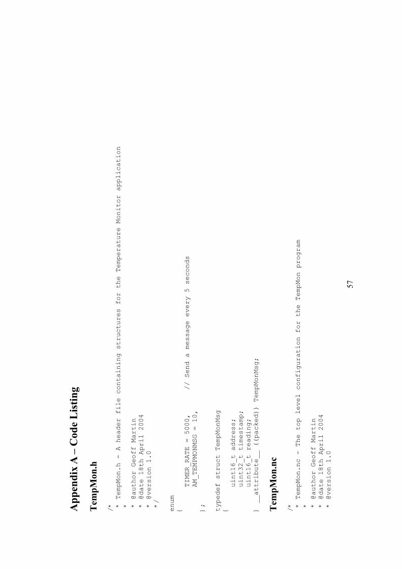
57
App
endi
x A
– C
ode
Lis
ting
Tem
pMon
.h
/*
* TempMon.h - A header file containing structures for the Temperature Monitor application
*
* @author Geoff Martin
* @date 18th April 2004
* @version 1.0
*/
enum
{
TIMER_RATE = 5000,
// Send a message every 5 seconds
AM_TEMPMONMSG = 10,
};
typedef struct TempMonMsg
{
uint16_t address;
uint32_t timestamp;
uint16_t reading;
} __attribute__ ((packed)) TempMonMsg;
Tem
pMon
.nc
/*
* TempMon.nc - The top level configuration for the TempMon program
*
* @author Geoff Martin
* @date 18th April 2004
* @version 1.0
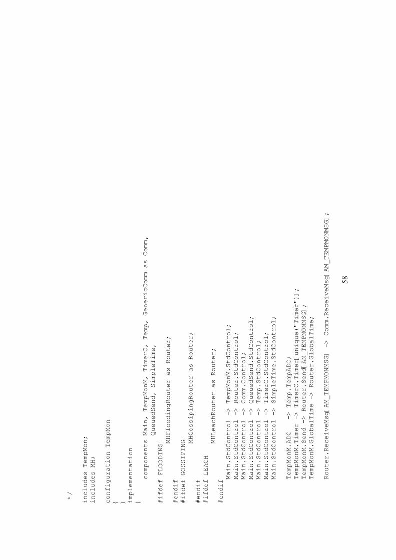
58
*/
includes TempMon;
includes MH;
configuration TempMon
{ } implementation
{
components Main, TempMonM, TimerC, Temp, GenericComm as Comm,
QueuedSend, SimpleTime,
#ifdef FLOODING
MHFloodingRouter as Router;
#endif
#ifdef GOSSIPING
MHGossipingRouter as Router;
#endif
#ifdef LEACH
MHLeachRouter as Router;
#endif
Main.StdControl -> TempMonM.StdControl;
Main.StdControl -> Router.StdControl;
Main.StdControl -> Comm.Control;
Main.StdControl -> QueuedSend.StdControl;
Main.StdControl -> Temp.StdControl;
Main.StdControl -> TimerC.StdControl;
Main.StdControl -> SimpleTime.StdControl;
TempMonM.ADC -> Temp.TempADC;
TempMonM.Timer -> TimerC.Timer[unique("Timer")];
TempMonM.Send -> Router.Send[AM_TEMPMONMSG];
TempMonM.GlobalTime -> Router.GlobalTime;
Router.ReceiveMsg[AM_TEMPMONMSG] -> Comm.ReceiveMsg[AM_TEMPMONMSG];

59
} T
empM
onM
.nc
/*
* TempMonM.nc - The implementation module for the TempMon application
*
* @author Geoff Martin
* @date 18th April 2004
* @version 1.0
*/
includes TempMon;
module TempMonM
{
provides
{
interface StdControl;
}
uses
{
interface Send;
interface ADC;
interface Timer;
interface GlobalTime;
}
} implementation
{
norace uint16_t sensorReading;
// Holds current sensor reading
bool sendBusy;
// Holds status of send
TOS_Msg mhMsg;
// Message to use when sending data
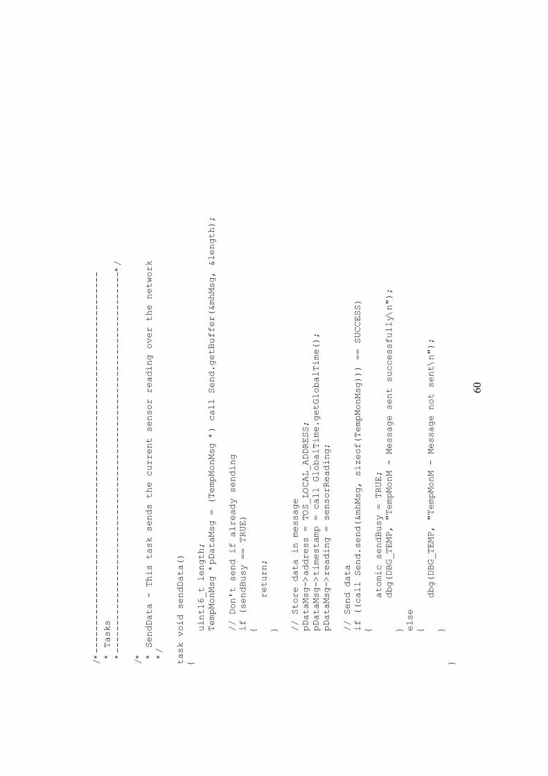
60
/*---------------------------------------------------------------------
* Tasks
*---------------------------------------------------------------------*/
/*
* SendData - This task sends the current sensor reading over the network
*/
task void sendData()
{
uint16_t length;
TempMonMsg *pDataMsg = (TempMonMsg *) call Send.getBuffer(&mhMsg, &length);
// Don't send if already sending
if (sendBusy == TRUE)
{
return;
}
// Store data in message
pDataMsg->address = TOS_LOCAL_ADDRESS;
pDataMsg->timestamp = call GlobalTime.getGlobalTime();
pDataMsg->reading = sensorReading;
// Send data
if ((call Send.send(&mhMsg, sizeof(TempMonMsg))) == SUCCESS)
{
atomic sendBusy = TRUE;
dbg(DBG_TEMP, "TempMonM - Message sent successfully\n");
}
else
{
dbg(DBG_TEMP, "TempMonM - Message not sent\n");
}
}
61
/*---------------------------------------------------------------------
* Provided Interface Commands
*---------------------------------------------------------------------*/
/*
* StdControl
*/
command result_t StdControl.init()
{
sendBusy = FALSE;
sensorReading = 0;
return SUCCESS;
}
command result_t StdControl.start()
{
call ADC.getData();
// Get reading from the ADC
return call Timer.start(TIMER_REPEAT, TIMER_RATE);
}
command result_t StdControl.stop()
{
return call Timer.stop();
}
/*---------------------------------------------------------------------
* Used Interface Events
*---------------------------------------------------------------------*/
/*
* Send
*/
62
// This event fires when sending is done
event result_t Send.sendDone(TOS_MsgPtr msg, result_t success)
{
atomic sendBusy = FALSE;
return SUCCESS;
}
/*
* ADC
*/
// This event fires when data is ready
async event result_t ADC.dataReady(uint16_t data)
{
dbg(DBG_TEMP, "TempMonM - Sensor reading taken from ADC\n");
atomic sensorReading = data;
return SUCCESS;
}
/*
* Timer
*/
// This event fires when the timer fires
event result_t Timer.fired()
{
call ADC.getData();
// Get reading from the ADC
// Send data if and only if the mote is syncronised to global time
if (call GlobalTime.isSynchronised() == SUCCESS)
{
post sendData();
}
return SUCCESS;
63
}
} T
imeS
yncM
..nc
/*
* TimeSyncM.nc - A module to handle time synchronisation
*
* @author Geoff Martin
* @date 18th April 2004
* @version 1.0
*/
includes AM;
module TimeSyncM
{
provides
{
interface StdControl;
interface GlobalTime;
}
uses
{
interface Timer;
interface Time;
interface ReceiveMsg;
interface SendMsg;
interface Leds;
}
} implementation
{
64
/*---------------------------------------------------------------------
* Types and Variables
*---------------------------------------------------------------------*/
/*
* Type Definitions
*/
typedef struct TimePacket
{
uint16_t nodeID;
uint32_t time;
} TimePacket;
/*
* Constants and variables
*/
enum
{
UPDATE_RATE = 5000,
// 5 seconds
HOP_DELAY = 22
// 22ms given by TimeSyncTest
};
int offset;
// Offset from actual time
bool synchronised;
// Is the mote synchronised
bool sendBusy;
// Sending busy flag
TOS_Msg timeMsg; // Message to store data to be sent in
/*---------------------------------------------------------------------
* Tasks
*---------------------------------------------------------------------*/
// Advertise current global time as known by this mote
task void advertise()
65
{
TimePacket *pTP = (TimePacket *) &timeMsg.data[0];
uint8_t length = sizeof(TimePacket);
// Don't send if already sending
if (sendBusy == TRUE)
{
return;
}
pTP->nodeID = TOS_LOCAL_ADDRESS;
pTP->time = call Time.getLow32() + offset;
// Send message
if (call SendMsg.send(TOS_BCAST_ADDR, length, &timeMsg) == SUCCESS)
{
// Toggle red LED to indicate transmit (Tx)
atomic
{
call Leds.redToggle();
}
atomic sendBusy = TRUE;
}
}
/*---------------------------------------------------------------------
* Provided Interface Commands
*---------------------------------------------------------------------*/
command result_t StdControl.init()
{
// Network synchronises on node 0
if (TOS_LOCAL_ADDRESS == 0)
{
66
offset = 0;
synchronised = TRUE;
}
else
{
synchronised = FALSE;
}
sendBusy = FALSE;
return SUCCESS;
}
command result_t StdControl.start()
{
return call Timer.start(TIMER_REPEAT, UPDATE_RATE);
}
command result_t StdControl.stop()
{
return call Timer.stop();
}
// Get if the mote is synchronised
command bool GlobalTime.isSynchronised()
{
return synchronised;
}
// Get the global time in milliseconds
command uint32_t GlobalTime.getGlobalTime()
{
// Return current global time or 0 if not synchronised
if (synchronised == TRUE)
{
return (call Time.getLow32() + offset);
67
}
else
{
return 0;
}
}
/*---------------------------------------------------------------------
* Used Interface Events
*---------------------------------------------------------------------*/
// Timer fired event
event result_t Timer.fired()
{
// Advertise global time if syncronised
if (synchronised == TRUE)
{
post advertise();
}
return SUCCESS;
}
// Receive message event
event TOS_MsgPtr ReceiveMsg.receive(TOS_MsgPtr m)
{
// Toggle red LED to indicate receive (Rx)
atomic
{
call Leds.redToggle();
}
// Determine time difference if not the base node
if (TOS_LOCAL_ADDRESS != 0)
{
TimePacket *pTP = (TimePacket *) m->data;
68
offset = (pTP->time + HOP_DELAY) - call Time.getLow32();
if (synchronised == FALSE)
{
synchronised = TRUE;
dbg(DBG_TEMP, "TimeSyncM - Node synchronised to global time\n");
}
}
return m;
}
// Event for signalling that send is done
event result_t SendMsg.sendDone(TOS_MsgPtr msg, result_t success)
{
atomic sendBusy = FALSE;
return SUCCESS;
}
} T
imeS
yncT
est.n
c
/*
* TimeSyncTest.nc - The configuration for the TimeSyncTest program
*
* @author Geoff Martin
* @date 18th April 2004
* @version 1.0
*/
configuration TimeSyncTest
{ } implementation
{
69
components Main, TimeSyncTestM, GenericComm, SimpleTime, TimerC;
Main.StdControl -> TimeSyncTestM.StdControl;
Main.StdControl -> GenericComm.Control;
Main.StdControl -> TimerC.StdControl;
Main.StdControl -> SimpleTime.StdControl;
TimeSyncTestM.SendMsg -> GenericComm.SendMsg[1];
TimeSyncTestM.ReceiveMsg -> GenericComm.ReceiveMsg[1];
TimeSyncTestM.Time -> SimpleTime.Time;
TimeSyncTestM.Timer -> TimerC.Timer[unique("Timer")];
} T
imeS
yncT
estM
.nc
/*
* TimeSyncTestM.nc - A module for determining the per hop delay between nodes
*
* @author Geoff Martin
* @date 18th April 2004
* @version 1.0
*/
includes AM;
module TimeSyncTestM
{
provides
{
interface StdControl;
}
uses
{
interface ReceiveMsg;
70
interface SendMsg;
interface Time;
interface Timer;
}
} implementation
{
/*---------------------------------------------------------------------
* Types and Variables
*---------------------------------------------------------------------*/
/*
* Type Definitions
*/
typedef struct TimePacket
{
uint16_t hops;
uint32_t time;
} __attribute__ ((packed)) TimePacket;
/*
* Node state
*/
TOS_Msg timeMsg; // Message to store data to be sent in
bool sendTimeBusy;
// Flag to indicate sending status
enum
{
HOPS = 100
};
// Select route for message
71
static result_t selectRoute(TOS_MsgPtr msg)
{
// If base send to 1
if (TOS_LOCAL_ADDRESS == 0)
{
msg->addr = 1;
return SUCCESS;
}
// If node 1 send to base
else if (TOS_LOCAL_ADDRESS == 1)
{
msg->addr = 0;
return SUCCESS;
}
return FAIL;
}
// Task to send the time at node
task void sendTime()
{
TimePacket *pTP = (TimePacket *) &timeMsg.data[0];
uint8_t length = sizeof(TimePacket);
pTP->hops = 0;
pTP->time = call Time.getLow32();
// Return if not a valid route
if (selectRoute(&timeMsg) != SUCCESS)
{
return;
}
// Return if already sending
if (sendTimeBusy == TRUE)
{
72
return;
}
// Send message
if (call SendMsg.send(TOS_BCAST_ADDR, length, &timeMsg) == SUCCESS)
{
atomic sendTimeBusy = TRUE;
}
}
/*---------------------------------------------------------------------
* Provided Interface Commands
*---------------------------------------------------------------------*/
/*
* StdControl
*/
command result_t StdControl.init()
{
sendTimeBusy = FALSE;
return SUCCESS;
}
command result_t StdControl.start()
{
// Delay first message by 10 seconds to give the network time to boot
if (TOS_LOCAL_ADDRESS == 0)
{
call Timer.start(TIMER_ONE_SHOT, 10000);
}
return SUCCESS;
}
command result_t StdControl.stop()
73
{
return SUCCESS;
}
/*---------------------------------------------------------------------
* Used Interface Events
*---------------------------------------------------------------------*/
// Event fires when message is received
event TOS_MsgPtr ReceiveMsg.receive(TOS_MsgPtr m)
{
uint32_t totalTime;
TimePacket *pTP = (TimePacket *) m->data;
pTP->hops++;
// Calculate time difference if base station and HOPS has been reached
if ((TOS_LOCAL_ADDRESS == 0) && (pTP->hops >= HOPS))
{
totalTime = (call Time.getLow32()) - pTP->time;
dbg(DBG_USR1, "TimeSyncTestM - Hops: %i, Time: %i\n", (int) pTP->hops, (int) totalTime);
post sendTime();
}
else // Forward
{
uint8_t length = sizeof(TimePacket);
// Drop if no route
if (selectRoute(m) != SUCCESS)
{
return m;
}
// Drop if already sending
74
if (sendTimeBusy == TRUE)
{
return m;
}
// Send message
if (call SendMsg.send(TOS_BCAST_ADDR, length, m) == SUCCESS)
{
atomic sendTimeBusy = TRUE;
}
}
return m;
}
// Event indicates that sending is done
event result_t SendMsg.sendDone(TOS_MsgPtr msg, result_t success)
{
atomic sendTimeBusy = FALSE;
return SUCCESS;
}
// Event fires when timer fires
event result_t Timer.fired()
{
post sendTime();
return SUCCESS;
}
}
75
Rou
teSe
lect
.nc
// $Id: RouteSelect.nc,v 1.3 2003/10/07 21:46:14 idgay Exp $
/*
tab:4
* "Copyright (c) 2000-2003 The Regents of the University of California.
* All rights reserved.
*
* Permission to use, copy, modify, and distribute this software and its
* documentation for any purpose, without fee, and without written agreement is
* hereby granted, provided that the above copyright notice, the following
* two paragraphs and the author appear in all copies of this software.
*
* IN NO EVENT SHALL THE UNIVERSITY OF CALIFORNIA BE LIABLE TO ANY PARTY FOR
* DIRECT, INDIRECT, SPECIAL, INCIDENTAL, OR CONSEQUENTIAL DAMAGES ARISING OUT
* OF THE USE OF THIS SOFTWARE AND ITS DOCUMENTATION, EVEN IF THE UNIVERSITY OF
* CALIFORNIA HAS BEEN ADVISED OF THE POSSIBILITY OF SUCH DAMAGE.
*
* THE UNIVERSITY OF CALIFORNIA SPECIFICALLY DISCLAIMS ANY WARRANTIES,
* INCLUDING, BUT NOT LIMITED TO, THE IMPLIED WARRANTIES OF MERCHANTABILITY
* AND FITNESS FOR A PARTICULAR PURPOSE. THE SOFTWARE PROVIDED HEREUNDER IS
* ON AN "AS IS" BASIS, AND THE UNIVERSITY OF CALIFORNIA HAS NO OBLIGATION TO
* PROVIDE MAINTENANCE, SUPPORT, UPDATES, ENHANCEMENTS, OR MODIFICATIONS."
*
* Copyright (c) 2002-2003 Intel Corporation
* All rights reserved.
*
* This file is distributed under the terms in the attached INTEL-LICENSE
* file. If you do not find these files, copies can be found by writing to
* Intel Research Berkeley, 2150 Shattuck Avenue, Suite 1300, Berkeley, CA,
* 94704. Attention: Intel License Inquiry.
*/
/*
* Authors:
Philip Levis
76
* Date last modified: 8/12/02
*
* The RouteSelect interface is part of the TinyOS ad-hoc routing
* system architecture. The component that keeps track of routing
* information and makes route selection decisions provides this
* interface. When a Send component wants to send a packet, it passes
* it to RouteSelect for its routing information to be filled in. This
* way, the Send component is entirely unaware of the routing
* header/footer structure.
*/
/**
* Interface to a route selection component in the TinyOS ad-hoc
* system architecture.
* @author Philip Levis
*
* modified by: Geoff Martin
* date: 18th April 2004
* modification made: getBuffer command removed as it is not needed
*/
includes AM;
interface RouteSelect {
/**
* Whether there is currently a valid route.
*
* @return Whether there is a valid route.
*/
command bool isActive();
/**
* Select a route and fill in all of the necessary routing
* information to a packet.
77
*
* @param msg Message to select route for and fill in routing information.
*
* @return Whether a route was selected succesfully. On FAIL the
* packet should not be sent.
*
*/
command result_t selectRoute(TOS_MsgPtr msg, uint8_t id);
/**
* Given a TOS_MstPtr, initialize its routing fields to a known
* state, specifying that the message is originating from this node.
* This known state can then be used by selectRoute() to fill in
* the necessary data.
*
* @param msg Message to select route for and fill in init data.
*
* @return Should always return SUCCESS.
*
*/
command result_t initializeFields(TOS_MsgPtr msg, uint8_t id);
} M
H.h
/*
* MH.h - A header file containing structures for multihop messaging
*
* @author Geoff Martin
* @date 18th April 2004
* @version 1.0
78
*/
#ifndef _TOS_MH_H
#define _TOS_MH_H
#include "AM.h"
// Default probability of 25%
#ifndef LEACH_PROBABILITY
#define LEACH_PROBABILITY 25
#endif
enum
{
AM_MHMESSAGE = 250,
AM_TIMESYNC = 100,
BASE_STATION_ADDRESS = 0,
FLOODING_MAX_HOP_COUNT = 100,
FLOODING_LOG_LENGTH = 250,
GOSSIPING_MAX_HOP_COUNT = 250,
GOSSIPING_NEIGHBOUR_TABLE_SIZE = 32,
GOSSIPING_ROUTE_UPDATE_RATE = 10000,
// 10 seconds
LEACH_ROUTE_UPDATE_RATE = 10000,
// 10 seconds
LEACH_ROUND_LENGTH = 600000,
// 10 minutes
LEACH_NEIGHBOUR_TABLE_SIZE = 32
};
typedef struct MHMessage
{
uint16_t sendingNode;
uint16_t originNode;
uint16_t seqNo;
79
uint16_t hopCount;
int8_t data[(TOSH_DATA_LENGTH - 8)];
} __attribute__ ((packed)) MHMessage;
#endif
MH
Eng
ineM
.nc
/*
* "Copyright (c) 2000-2003 The Regents of the University of California.
* All rights reserved.
*
* Permission to use, copy, modify, and distribute this software and its
* documentation for any purpose, without fee, and without written agreement is
* hereby granted, provided that the above copyright notice, the following
* two paragraphs and the author appear in all copies of this software.
*
* IN NO EVENT SHALL THE UNIVERSITY OF CALIFORNIA BE LIABLE TO ANY PARTY FOR
* DIRECT, INDIRECT, SPECIAL, INCIDENTAL, OR CONSEQUENTIAL DAMAGES ARISING OUT
* OF THE USE OF THIS SOFTWARE AND ITS DOCUMENTATION, EVEN IF THE UNIVERSITY OF
* CALIFORNIA HAS BEEN ADVISED OF THE POSSIBILITY OF SUCH DAMAGE.
*
* THE UNIVERSITY OF CALIFORNIA SPECIFICALLY DISCLAIMS ANY WARRANTIES,
* INCLUDING, BUT NOT LIMITED TO, THE IMPLIED WARRANTIES OF MERCHANTABILITY
* AND FITNESS FOR A PARTICULAR PURPOSE. THE SOFTWARE PROVIDED HEREUNDER IS
* ON AN "AS IS" BASIS, AND THE UNIVERSITY OF CALIFORNIA HAS NO OBLIGATION TO
* PROVIDE MAINTENANCE, SUPPORT, UPDATES, ENHANCEMENTS, OR MODIFICATIONS."
*
* Copyright (c) 2002-2003 Intel Corporation
* All rights reserved.
*
* This file is distributed under the terms in the attached INTEL-LICENSE
* file. If you do not find these files, copies can be found by writing to
* Intel Research Berkeley, 2150 Shattuck Avenue, Suite 1300, Berkeley, CA,
80
* 94704. Attention: Intel License Inquiry.
*/
/*
* A simple module that handles multihop packet movement. It accepts
* messages from both applications and the network and does the necessary
* interception and forwarding.
* It interfaces to an algorithmic componenet via RouteSelect. It also acts
* as a front end for RouteControl
*/
/*
* modified by: Geoff Martin
* date: 18/04/2004
*
* Note: In order to enable the code to record details about the operation of
* the protocol SIM must be defined. In addition the number of nodes
* must be assigned to SIM.
*/
includes AM;
includes MH;
#ifndef MHOP_QUEUE_SIZE
#define MHOP_QUEUE_SIZE 32
#endif
module MHEngineM
{
provides
{
interface StdControl;
interface Receive[uint8_t id];
interface Send[uint8_t id];
interface Intercept[uint8_t id];

81
}
uses
{
interface ReceiveMsg[uint8_t id];
interface SendMsg[uint8_t id];
interface RouteSelect;
interface StdControl as SubControl;
interface StdControl as CommStdControl;
interface GlobalTime;
#ifdef SIM
interface Timer as SimTimer;
#endif
interface Leds;
}
} implementation
{
enum
{
FWD_QUEUE_SIZE = MHOP_QUEUE_SIZE, // Forwarding Queue
EMPTY = 0xff
};
/* Internal storage and scheduling state */
struct TOS_Msg FwdBuffers[FWD_QUEUE_SIZE];
struct TOS_Msg *FwdBufList[FWD_QUEUE_SIZE];
uint8_t iFwdBufHead, iFwdBufTail;
/***********************************************************************
* Simulation variables and methods
***********************************************************************/
#ifdef SIM
int sent, received, forwarded, usedBattery;
82
// Values to allow an approximation of used power. Transmit requires about 1/3 more power than receive
enum
{
RECEIVE = 2,
TRANSMIT = 3
};
// Allows the number of messages received at the base station to be tracked during simulation
typedef struct SimulationStats
{
uint32_t received;
uint32_t totalTime;
uint32_t totalHopTime;
uint32_t worstTime;
uint32_t worstHopTime;
uint32_t bestTime;
uint32_t bestHopTime;
} SimulationStats;
// Simulation statistics table
SimulationStats simStats[SIM];
// This method updates a nodes entry in the simulation statistics table
static void updateSimStats(uint16_t nodeID, uint32_t timeTaken, uint16_t hopCount)
{
uint32_t hopTime;
simStats[nodeID].received++;
// Avoids division by 0 and makes no difference to results
if (hopCount == 0)
{
hopCount++;
}
83
// Per hop time
hopTime = timeTaken / hopCount;
// Set worst and best time values when the first packet is received
if (simStats[nodeID].received == 1)
{
simStats[nodeID].worstTime = simStats[nodeID].bestTime = timeTaken;
simStats[nodeID].worstHopTime = simStats[nodeID].bestHopTime = hopTime;
}
// Add the time taken by the packet to the total time taken by all packets
simStats[nodeID].totalTime += timeTaken;
simStats[nodeID].totalHopTime += hopTime;
// If the time taken is the worst time so far
if (simStats[nodeID].worstTime < timeTaken)
{
simStats[nodeID].worstTime = timeTaken;
}
// If the time taken per hop is the worst time so far
if (simStats[nodeID].worstHopTime < hopTime)
{
simStats[nodeID].worstHopTime = hopTime;
}
// If the time taken is the best time so far
if (simStats[nodeID].bestTime > timeTaken)
{
simStats[nodeID].bestTime = timeTaken;
}
// If the time taken per hop is the best time so far
if (simStats[nodeID].bestHopTime > hopTime)
84
{
simStats[nodeID].bestHopTime = hopTime;
}
}
#endif
/***********************************************************************
* Initialization
***********************************************************************/
static void initialize()
{
int n;
for (n=0; n < FWD_QUEUE_SIZE; n++)
{
FwdBufList[n] = &FwdBuffers[n];
}
iFwdBufHead = iFwdBufTail = 0;
}
#ifdef SIM
// Initialize the simulation stats table
static void initializeSimStats()
{
int i;
sent = received = forwarded = usedBattery = 0;
if (TOS_LOCAL_ADDRESS == 0)
{
for (i = 0; i < SIM; i++)
{
simStats[i].received
=
simStats[i].totalTime
=
simStats[i].worstTime
=
simStats[i].bestTime = 0;
85
}
}
}
#endif
command result_t StdControl.init()
{
initialize();
#ifdef SIM
initializeSimStats();
#endif
call Leds.init();
call CommStdControl.init();
return call SubControl.init();
}
command result_t StdControl.start()
{
call CommStdControl.start();
#ifdef SIM
call SimTimer.start(TIMER_REPEAT, 1800000);
// Display results after 30 mins
#endif
return call SubControl.start();
}
command result_t StdControl.stop()
{
call SubControl.stop();
#ifdef SIM
call SimTimer.stop();
#endif
// XXX message doesn't get received if we stop then start radio
return call CommStdControl.stop();
}
/***********************************************************************
86
* Commands and events
***********************************************************************/
command result_t Send.send[uint8_t id](TOS_MsgPtr pMsg, uint16_t PayloadLen)
{
uint16_t usMHLength = offsetof(MHMessage,data) + PayloadLen;
if (usMHLength > TOSH_DATA_LENGTH)
{
dbg(DBG_TEMP, "MHEngineM - Sending of packet failed\n");
return FAIL;
}
call RouteSelect.initializeFields(pMsg,id);
if (call RouteSelect.selectRoute(pMsg,id) != SUCCESS)
{
dbg(DBG_TEMP, "MHEngineM - Sending of packet failed due to no route\n");
return FAIL;
}
if (call SendMsg.send[id](pMsg->addr, usMHLength, pMsg) != SUCCESS)
{
dbg(DBG_TEMP, "MHEngineM - Sending of packet failed\n");
return FAIL;
}
else
{
// Toggle red LED to indicate transmit (Tx)
atomic
{
call Leds.redToggle();
}
#ifdef SIM
sent++;
87
usedBattery+=TRANSMIT;
if (TOS_LOCAL_ADDRESS == 0)
{
MHMessage *pMH = (MHMessage *) pMsg->data;
TempMonMsg *pTM = (TempMonMsg *) pMH->data;
uint32_t timeTaken = call GlobalTime.getGlobalTime() - pTM->timestamp;
dbg(DBG_TEMP, "MHEngineM - Packet received at base station from node %i\n", pMH-
>originNode);
updateSimStats(pMH->originNode, timeTaken, pMH->hopCount);
}
#endif
}
dbg(DBG_TEMP, "MHEngineM - Sending of packet successfull\n");
return SUCCESS;
}
command void *Send.getBuffer[uint8_t id](TOS_MsgPtr pMsg, uint16_t* length)
{
MHMessage *pMHMsg = (MHMessage *)pMsg->data;
*length = TOSH_DATA_LENGTH - offsetof(MHMessage,data);
return (&pMHMsg->data[0]);
}
static TOS_MsgPtr mForward(TOS_MsgPtr pMsg, uint8_t id)
{
TOS_MsgPtr pNewBuf = pMsg;
if (((iFwdBufHead + 1) % FWD_QUEUE_SIZE) == iFwdBufTail)
{
dbg(DBG_TEMP, "MHEngineM - Forwarding of packet failed\n");
return pNewBuf;
}
if ((call RouteSelect.selectRoute(pMsg,id)) != SUCCESS)
88
{
dbg(DBG_TEMP, "MHEngineM - Forwarding of packet failed due to no route\n");
return pNewBuf;
}
if (call SendMsg.send[id](pMsg->addr,pMsg->length,pMsg) == SUCCESS)
{
// Toggle red LED to indicate transmit (Tx)
atomic
{
call Leds.redToggle();
}
#ifdef SIM
if (TOS_LOCAL_ADDRESS == 0)
{
MHMessage *pMH = (MHMessage *) pMsg->data;
TempMonMsg *pTM = (TempMonMsg *) pMH->data;
uint32_t timeTaken = call GlobalTime.getGlobalTime() - pTM->timestamp;
dbg(DBG_TEMP, "MHEngineM - Packet received at base station from node %i\n", pMH-
>originNode);
updateSimStats(pMH->originNode, timeTaken, pMH->hopCount);
}
forwarded++;
usedBattery+=TRANSMIT;
#endif
pNewBuf = FwdBufList[iFwdBufHead];
FwdBufList[iFwdBufHead] = pMsg;
iFwdBufHead++; iFwdBufHead %= FWD_QUEUE_SIZE;
}
dbg(DBG_TEMP, "MHEngineM - Forwarding of packet successfull\n");
return pNewBuf;
}
event TOS_MsgPtr ReceiveMsg.receive[uint8_t id](TOS_MsgPtr pMsg)
89
{
MHMessage *pMHMsg = (MHMessage *)pMsg->data;
uint16_t PayloadLen = pMsg->length - offsetof(MHMessage,data);
// Toggle red LED to indicate receive (Rx)
atomic
{
call Leds.redToggle();
}
// Ordinary message requiring forwarding
if (pMsg->addr == TOS_LOCAL_ADDRESS ||
pMsg->addr == TOS_BCAST_ADDR) // Addressed to local node or Broadcast address
{
if ((signal Intercept.intercept[id](pMsg,&pMHMsg->data[0],PayloadLen)) == SUCCESS)
{
pMsg = mForward(pMsg,id);
}
}
#ifdef SIM
received++;
usedBattery+=RECEIVE;
#endif
return pMsg;
}
event result_t SendMsg.sendDone[uint8_t id](TOS_MsgPtr pMsg, result_t success)
{
if (pMsg == FwdBufList[iFwdBufTail]) // Msg was from forwarding queue
{
iFwdBufTail++;
iFwdBufTail %= FWD_QUEUE_SIZE;
}
else
{

90
signal Send.sendDone[id](pMsg, success);
}
return SUCCESS;
}
default event result_t Send.sendDone[uint8_t id](TOS_MsgPtr pMsg, result_t success)
{
return SUCCESS;
}
default
event
result_t
Intercept.intercept[uint8_t
id](TOS_MsgPtr
pMsg,
void*
payload,
uint16_t
payloadLen)
{
return SUCCESS;
}
#ifdef SIM
// Print out simulator variables after 30 minutes
event result_t SimTimer.fired()
{
int i;
dbg(DBG_USR1, "Sent: %i, Received: %i, Forwarded: %i, Used Power: %i\n", sent, received, forwarded,
usedBattery);
if (TOS_LOCAL_ADDRESS == 0)
{
atomic
{
dbg(DBG_USR1,
"Node\tReceived\tBest\tHop
Best\tWorst\tHop
Worst\tAverage\tHop
Average\n");
for (i = 0; i < SIM; i++)
{
uint32_t average, hopAverage, recCount;
91
recCount = simStats[i].received;
// Makes no difference but avoids division by 0
if (recCount == 0)
{
recCount++;
}
average = simStats[i].totalTime / recCount;
hopAverage = simStats[i].totalHopTime / recCount;
dbg(DBG_USR1,
"%i\t%i\t%i\t%i\t%i\t%i\t%i\t%i\n",
i,
simStats[i].received,
simStats[i].bestTime,
simStats[i].bestHopTime,
simStats[i].worstTime,
simStats[i].worstHopTime,
average,
hopAverage);
}
}
}
return SUCCESS;
}
#endif
} M
HFl
oodi
ngR
oute
r.nc
/*
* MHFloodingRouter.nc - The configuration for the Flooding version of the router
*
* @author Geoff Martin
* @date 18th April 2004
* @version 1.0
*/
includes MH;
configuration MHFloodingRouter
92
{
provides
{
interface StdControl;
interface Receive[uint8_t id];
interface Send[uint8_t id];
interface Intercept[uint8_t id];
interface GlobalTime;
}
uses
{
interface ReceiveMsg[uint8_t id];
}
} implementation
{
components MHEngineM, MHFloodingPSM, GenericComm as Comm, QueuedSend, TimerC, SimpleTime, TimeSyncM,
LedsC;
StdControl = MHEngineM.StdControl;
Receive = MHEngineM.Receive;
Send = MHEngineM.Send;
ReceiveMsg = MHEngineM.ReceiveMsg;
Intercept = MHEngineM.Intercept;
GlobalTime = TimeSyncM.GlobalTime;
MHEngineM.CommStdControl -> Comm.Control;
#ifdef SIM
MHEngineM.SimTimer -> TimerC.Timer[unique("Timer")];
#endif
MHEngineM.SubControl -> QueuedSend.StdControl;
MHEngineM.SendMsg -> QueuedSend.SendMsg;
MHEngineM.SubControl -> MHFloodingPSM.StdControl;
93
MHEngineM.RouteSelect -> MHFloodingPSM.RouteSelect;
MHEngineM.Leds -> LedsC.Leds;
TimeSyncM.Leds -> LedsC.Leds;
MHEngineM.SubControl -> TimeSyncM.StdControl;
TimeSyncM.Timer -> TimerC.Timer[unique("Timer")];
TimeSyncM.Time -> SimpleTime.Time;
TimeSyncM.ReceiveMsg -> Comm.ReceiveMsg[AM_TIMESYNC];
TimeSyncM.SendMsg -> QueuedSend.SendMsg[AM_TIMESYNC];
MHEngineM.GlobalTime -> TimeSyncM.GlobalTime;
} M
HFl
oodi
ngPS
M.n
c
/*
* MHFloodingPSM.nc - The flooding logic for multihop messaging
*
* @author Geoff Martin
* @date 18th April 2004
* @version 1.0
*/
includes AM;
includes MH;
module MHFloodingPSM
{
provides
{
interface StdControl;
interface RouteSelect;
}

94
} implementation
{
/*---------------------------------------------------------------------
* Types and Variables
*---------------------------------------------------------------------*/
/*
* Type Definitions
*/
typedef struct LogEntry
{
uint16_t id;
uint16_t seqno;
} LogEntry;
/*
* Constant Definitions
*/
enum
{
MAX_HOP_COUNT = FLOODING_MAX_HOP_COUNT,
MAX_SEQ_NO = 30000,
// 0 - 29999 allowed
LOG_LENGTH = FLOODING_LOG_LENGTH
};
/*
* Node state
*/
uint16_t seqNo;
95
/*
* Previous message log to limit duplicate packets
*/
LogEntry messageLog[LOG_LENGTH];
uint16_t entries; // Number of entries
uint16_t index;
// Current index in log
// Get next sequence number
static uint16_t getSeqNo()
{
uint16_t temp = seqNo++;
seqNo = seqNo % MAX_SEQ_NO;
return temp;
}
/*---------------------------------------------------------------------
* Message log methods
*---------------------------------------------------------------------*/
// Add a new log entry
static void addLogEntry(uint16_t id, uint16_t seqno)
{
if (entries < LOG_LENGTH)
{
entries++;
}
messageLog[index].id = id;
messageLog[index++].seqno = seqno;
index = index % LOG_LENGTH;
}
96
// Find an entry in the log
static bool inLog(uint16_t id, uint16_t seqno)
{
int i;
for (i = 0; i < entries; i++)
{
if ((messageLog[i].id == id) && (messageLog[i].seqno == seqno))
{
return TRUE;
}
}
return FALSE;
}
/*---------------------------------------------------------------------
* Provided Interface Commands
*---------------------------------------------------------------------*/
/*
* StdControl
*/
command result_t StdControl.init()
{
seqNo = 0;
entries = 0;
index = 0;
return SUCCESS;
}
command result_t StdControl.start()
{
return SUCCESS;
97
}
command result_t StdControl.stop()
{
return SUCCESS;
}
/*
* RouteSelect
*/
command bool RouteSelect.isActive()
{
return TRUE;
// Always a valid route when flooding
}
// Select route for packet
command result_t RouteSelect.selectRoute(TOS_MsgPtr msg, uint8_t id)
{
MHMessage *pMHMsg = (MHMessage *) &msg->data[0];
// If packet has been generated by local node
if ((pMHMsg->originNode == TOS_LOCAL_ADDRESS) &&
(pMHMsg->hopCount == 0))
{
pMHMsg->seqNo = getSeqNo();
}
// If message is new at node
else if (inLog(pMHMsg->originNode, pMHMsg->seqNo) == FALSE)
{
pMHMsg->sendingNode = TOS_LOCAL_ADDRESS;
pMHMsg->hopCount++;
}
else
{

98
dbg(DBG_TEMP, "MHFloodingPSM - Failed to select route for duplicate packet\n");
return FAIL;
}
// If base station send to UART
if (TOS_LOCAL_ADDRESS == BASE_STATION_ADDRESS)
{
msg->addr = TOS_UART_ADDR;
}
else
{
msg->addr = TOS_BCAST_ADDR;
}
// Drop packet if hop count has exceeded maximum unless the packet is to be forwarded to the UART
if (pMHMsg->hopCount < MAX_HOP_COUNT || msg->addr == TOS_UART_ADDR)
{
addLogEntry(pMHMsg->originNode, pMHMsg->seqNo);
dbg(DBG_TEMP, "MHFloodingPSM - Route selected\n");
return SUCCESS;
}
dbg(DBG_TEMP, "MHFloodingPSM - Failed to select route\n");
return FAIL;
}
// Initilise fields for a new packet
command result_t RouteSelect.initializeFields(TOS_MsgPtr msg, uint8_t id)
{
MHMessage *pMHMsg = (MHMessage *) &msg->data[0];
pMHMsg->originNode = pMHMsg->sendingNode = TOS_LOCAL_ADDRESS;
pMHMsg->hopCount = 0;
return SUCCESS;
99
}
} M
HG
ossi
ping
Rou
ter.
nc
/*
* MHGossipingRouter.nc - The configuration for the Gossiping router
*
* @author Geoff Martin
* @date 18th April 2004
* @version 1.0
*/
includes MH;
configuration MHGossipingRouter
{
provides
{
interface StdControl;
interface Receive[uint8_t id];
interface Send[uint8_t id];
interface Intercept[uint8_t id];
interface GlobalTime;
}
uses
{
interface ReceiveMsg[uint8_t id];
}
} implementation
{
10
0
components MHEngineM, MHGossipingPSM, GenericComm as Comm, QueuedSend, TimerC, RandomLFSR, SimpleTime,
TimeSyncM, LedsC;
StdControl = MHEngineM.StdControl;
Receive = MHEngineM.Receive;
Send = MHEngineM.Send;
ReceiveMsg = MHEngineM.ReceiveMsg;
Intercept = MHEngineM.Intercept;
GlobalTime = TimeSyncM.GlobalTime;
MHEngineM.CommStdControl -> Comm.Control;
#ifdef SIM
MHEngineM.SimTimer -> TimerC.Timer[unique("Timer")];
#endif
MHEngineM.SubControl -> QueuedSend.StdControl;
MHEngineM.SendMsg -> QueuedSend.SendMsg;
MHEngineM.SubControl -> MHGossipingPSM.StdControl;
MHEngineM.RouteSelect -> MHGossipingPSM.RouteSelect;
MHGossipingPSM.Timer -> TimerC.Timer[unique("Timer")];
MHGossipingPSM.ReceiveMsg -> Comm.ReceiveMsg[AM_MHMESSAGE];
MHGossipingPSM.SendMsg -> QueuedSend.SendMsg[AM_MHMESSAGE];
MHGossipingPSM.Random -> RandomLFSR.Random;
MHEngineM.Leds -> LedsC.Leds;
TimeSyncM.Leds -> LedsC.Leds;
MHGossipingPSM.Leds -> LedsC.Leds;
MHEngineM.SubControl -> TimeSyncM.StdControl;
TimeSyncM.Timer -> TimerC.Timer[unique("Timer")];
TimeSyncM.Time -> SimpleTime.Time;
TimeSyncM.ReceiveMsg -> Comm.ReceiveMsg[AM_TIMESYNC];
10
1
TimeSyncM.SendMsg -> QueuedSend.SendMsg[AM_TIMESYNC];
MHEngineM.GlobalTime -> TimeSyncM.GlobalTime;
} M
HG
ossi
ping
PSM
.nc
/*
* MHGossipingPSM.nc - The gossiping logic for multihop messaging
*
* @author Geoff Martin
* @date 18th April 2004
* @version 1.0
*/
includes AM;
includes MH;
module MHGossipingPSM
{
provides
{
interface StdControl;
interface RouteSelect;
}
uses
{
interface Timer;
interface ReceiveMsg;
interface SendMsg;
interface Random;
interface Leds;
}
}
10
2
implementation
{
/*---------------------------------------------------------------------
* Types and Variables
*---------------------------------------------------------------------*/
/*
* Type Definitions
*/
typedef struct RoutePacket
{
uint16_t nodeID;
} __attribute__ ((packed)) RoutePacket;
typedef struct NeighbourTable
{
uint16_t nodeID;
// Node ID
uint16_t receivedCount;
// Number of messages received
uint16_t timerTicks;
// Timer ticks since last packet
bool nodeAlive;
// Node status
uint16_t strength;
// Strength of link
} NeighbourTable;
/*
* Constant Definitions
*/
enum
{
MAX_HOP_COUNT = GOSSIPING_MAX_HOP_COUNT,
NEIGHBOUR_TABLE_SIZE = GOSSIPING_NEIGHBOUR_TABLE_SIZE,
NEIGHBOUR_DEAD_TICKS = 5,
ROUTE_UPDATE_RATE = GOSSIPING_ROUTE_UPDATE_RATE
10
3
};
/*
* Node state
*/
TOS_Msg routeMsg; // Variable to use to store route messages
bool sendRouteBusy;
// Indicates that send is busy
/*
* Neighbour table and state
*/
NeighbourTable neighbourTable[NEIGHBOUR_TABLE_SIZE];
uint16_t entries;
/*---------------------------------------------------------------------
* Route table update
*---------------------------------------------------------------------*/
// Update entry in table
static void updateTableEntry(uint16_t id, uint16_t strength)
{
int entryIndex, lowestStrengthIndex, nodeDeadIndex;
uint16_t lowestStrength = 0;
lowestStrengthIndex = nodeDeadIndex = entries;
// Search table
for (entryIndex = 0; entryIndex < entries; entryIndex++)
{
// If an entry already exists
if (neighbourTable[entryIndex].nodeID == id)
{
break;
}
10
4
// Else if the node is dead
else if ((neighbourTable[entryIndex].nodeAlive == FALSE) && (nodeDeadIndex == entries))
{
nodeDeadIndex = entryIndex;
}
// Else if the node has the lowest strength in the table so far
else if ((neighbourTable[entryIndex].strength < lowestStrength) || (lowestStrengthIndex ==
entries))
{
lowestStrengthIndex = entryIndex;
lowestStrength = neighbourTable[entryIndex].strength;
}
}
if (entryIndex < entries)
// Update entry in table
{
dbg(DBG_TEMP, "MHGossipingPSM - Updating entry for node %i in neighbour table\n", id);
neighbourTable[entryIndex].receivedCount++;
neighbourTable[entryIndex].timerTicks = 0;
neighbourTable[entryIndex].nodeAlive = TRUE;
neighbourTable[entryIndex].strength = strength;
}
else if (nodeDeadIndex != entries)
// Replace a dead node
{
dbg(DBG_TEMP, "MHGossipingPSM - Replacing dead node %i for node %i in neighbour table\n",
neighbourTable[nodeDeadIndex].nodeID, id);
neighbourTable[nodeDeadIndex].nodeID = id;
neighbourTable[nodeDeadIndex].receivedCount = 1;
neighbourTable[nodeDeadIndex].timerTicks = 0;
neighbourTable[nodeDeadIndex].nodeAlive = TRUE;
neighbourTable[nodeDeadIndex].strength = strength;
}
else if (entries < NEIGHBOUR_TABLE_SIZE)
// Add a new entry if table not full
{
dbg(DBG_TEMP, "MHGossipingPSM - Adding entry for node %i in neighbour table\n", id);
10
5
neighbourTable[entries].nodeID = id;
neighbourTable[entries].receivedCount = 1;
neighbourTable[entries].timerTicks = 0;
neighbourTable[entries].nodeAlive = TRUE;
neighbourTable[entries++].strength = strength;
}
else if (strength > lowestStrength)
// Replace a node of a lower strength
{
dbg(DBG_TEMP, "MHGossipingPSM - Replacing node %i for node %i in neighbour table\n",
neighbourTable[lowestStrengthIndex].nodeID, id);
neighbourTable[lowestStrengthIndex].nodeID = id;
neighbourTable[lowestStrengthIndex].receivedCount = 1;
neighbourTable[lowestStrengthIndex].timerTicks = 0;
neighbourTable[lowestStrengthIndex].nodeAlive = TRUE;
neighbourTable[lowestStrengthIndex].strength = strength;
}
}
// Update table
task void updateTable()
{
int i;
for (i = 0; i < entries; i++)
{
// Only update ticks if node is alive - this avoids infinite ticks
if (neighbourTable[i].nodeAlive == TRUE)
{
neighbourTable[i].timerTicks++;
if (neighbourTable[i].timerTicks >= NEIGHBOUR_DEAD_TICKS)
{
dbg(DBG_TEMP, "MHGossipingPSM - Setting node %i as dead in neighbour table\n",
neighbourTable[i].nodeID);
neighbourTable[i].nodeAlive = FALSE;
10
6
}
}
}
}
/*---------------------------------------------------------------------
* Route advertisement
*---------------------------------------------------------------------*/
task void advertise()
{
RoutePacket *pRP = (RoutePacket *) &routeMsg.data[0];
uint8_t length = sizeof(RoutePacket);
// Don't send if channel is in use
if (sendRouteBusy == TRUE)
{
return;
}
pRP->nodeID = TOS_LOCAL_ADDRESS;
// Send data
if (call SendMsg.send(TOS_BCAST_ADDR, length, &routeMsg) == SUCCESS)
{
// Toggle red LED to indicate transmit (Tx)
atomic
{
call Leds.redToggle();
}
dbg(DBG_TEMP, "MHGossipingPSM - Advertising presence\n");
atomic sendRouteBusy = TRUE;
}
}
10
7
/*---------------------------------------------------------------------
* Provided Interface Commands
*---------------------------------------------------------------------*/
/*
* StdControl
*/
command result_t StdControl.init()
{
entries = 0;
sendRouteBusy = FALSE;
call Random.init();
return SUCCESS;
}
command result_t StdControl.start()
{
return call Timer.start(TIMER_REPEAT, ROUTE_UPDATE_RATE);
}
command result_t StdControl.stop()
{
return call Timer.stop();
}
/*
* RouteSelect
*/
// If an alive entry is found there is an active route
command bool RouteSelect.isActive()
{
int i;
10
8
bool alive = FALSE;
for (i = 0; i < entries; i++)
{
if (neighbourTable[i].nodeAlive == TRUE)
{
alive = TRUE;
break;
}
}
return alive;
}
// Select route
command result_t RouteSelect.selectRoute(TOS_MsgPtr msg, uint8_t id)
{
MHMessage *pMHMsg = (MHMessage *) &msg->data[0];
// If the packet has arrived from another node
if (pMHMsg->sendingNode != TOS_LOCAL_ADDRESS)
{
pMHMsg->sendingNode = TOS_LOCAL_ADDRESS;
pMHMsg->hopCount++;
}
// If the current node is the base station address to the UART
if (TOS_LOCAL_ADDRESS == BASE_STATION_ADDRESS)
{
msg->addr = TOS_UART_ADDR;
}
else if (entries > 0)
// Else pick a random entry
{
uint16_t num = call Random.rand() % entries;
int i;
10
9
for (i = 0; i < entries; i++)
{
if (neighbourTable[num].nodeAlive == TRUE)
{
msg->addr = neighbourTable[num].nodeID;
break;
}
else
{
num++;
num = num % entries;
}
}
if (i == entries)
{
dbg(DBG_TEMP, "MHGossipingPSM - Failed to select route\n");
return FAIL;
}
}
else
{
dbg(DBG_TEMP, "MHGossipingPSM - Failed to select route\n");
return FAIL;
}
// Drop packet if hop count has exceeded maximum unless the packet is to be forwarded to the UART
if (pMHMsg->hopCount < MAX_HOP_COUNT || msg->addr == TOS_UART_ADDR)
{
dbg(DBG_TEMP, "MHGossipingPSM - Route selected\n");
return SUCCESS;
}
dbg(DBG_TEMP, "MHGossipingPSM - Failed to select route - hop count exceeded\n");

11
0
return FAIL;
}
// Initilise routing fields for a new packet
command result_t RouteSelect.initializeFields(TOS_MsgPtr msg, uint8_t id)
{
MHMessage *pMHMsg = (MHMessage *) &msg->data[0];
pMHMsg->originNode = pMHMsg->sendingNode = TOS_LOCAL_ADDRESS;
pMHMsg->hopCount = 0;
return SUCCESS;
}
/*---------------------------------------------------------------------
* Used Interface Events
*---------------------------------------------------------------------*/
// Event occurs when the timer fires
event result_t Timer.fired()
{
post updateTable();
// Increment a timer tick since last message field and set as inactive if
above limit
post advertise();
return SUCCESS;
}
// Event occurs when a route update message arrives
event TOS_MsgPtr ReceiveMsg.receive(TOS_MsgPtr m)
{
RoutePacket *pRP = (RoutePacket *) m->data;
// Toggle red LED to indicate receive (Rx)
atomic
{
11
1
call Leds.redToggle();
}
dbg(DBG_TEMP, "MHGossipingPSM - Advertisment received from node %i\n", pRP->nodeID);
updateTableEntry(pRP->nodeID, m->strength);
return m;
}
// Event occurs when sending a route update message is finished
event result_t SendMsg.sendDone(TOS_MsgPtr msg, result_t success)
{
atomic sendRouteBusy = FALSE;
return SUCCESS;
}
} M
HL
each
Rou
ter.
nc
/*
* MHLeachRouter.nc - The configuration for the LEACH router
*
* @author Geoff Martin
* @date 18th April 2004
* @version 1.0
*/
includes MH;
configuration MHLeachRouter
{
provides
{
11
2
interface StdControl;
interface Receive[uint8_t id];
interface Send[uint8_t id];
interface Intercept[uint8_t id];
interface GlobalTime;
}
uses
{
interface ReceiveMsg[uint8_t id];
}
} implementation
{
components MHEngineM, MHLeachPSM, GenericComm as Comm, QueuedSend, TimerC, RandomLFSR, SimpleTime,
TimeSyncM, LedsC;
StdControl = MHEngineM.StdControl;
Receive = MHEngineM.Receive;
Send = MHEngineM.Send;
ReceiveMsg = MHEngineM.ReceiveMsg;
Intercept = MHEngineM.Intercept;
GlobalTime = TimeSyncM.GlobalTime;
MHEngineM.CommStdControl -> Comm.Control;
#ifdef SIM
MHEngineM.SimTimer -> TimerC.Timer[unique("Timer")];
#endif
MHEngineM.SubControl -> QueuedSend.StdControl;
MHEngineM.SendMsg -> QueuedSend.SendMsg;
MHEngineM.SubControl -> MHLeachPSM.StdControl;
MHEngineM.RouteSelect -> MHLeachPSM.RouteSelect;
MHLeachPSM.StatusTimer -> TimerC.Timer[unique("Timer")];
11
3
MHLeachPSM.RoundTimer -> TimerC.Timer[unique("Timer")];
MHLeachPSM.ReceiveMsg -> Comm.ReceiveMsg[AM_MHMESSAGE];
MHLeachPSM.SendMsg -> QueuedSend.SendMsg[AM_MHMESSAGE];
MHLeachPSM.Random -> RandomLFSR.Random;
MHEngineM.Leds -> LedsC.Leds;
TimeSyncM.Leds -> LedsC.Leds;
MHLeachPSM.Leds -> LedsC.Leds;
MHEngineM.SubControl -> TimeSyncM.StdControl;
TimeSyncM.Timer -> TimerC.Timer[unique("Timer")];
TimeSyncM.Time -> SimpleTime.Time;
TimeSyncM.ReceiveMsg -> Comm.ReceiveMsg[AM_TIMESYNC];
TimeSyncM.SendMsg -> QueuedSend.SendMsg[AM_TIMESYNC];
MHEngineM.GlobalTime -> TimeSyncM.GlobalTime;
} M
HL
each
PSM
.nc
/*
* MHLeachPSM.nc - The LEACH logic for multihop messaging
*
* @author Geoff Martin
* @date 18th April 2004
* @version 1.0
*/
includes AM;
includes MH;
module MHLeachPSM

11
4
{
provides
{
interface StdControl;
interface RouteSelect;
}
uses
{
interface Timer as RoundTimer;
interface Timer as StatusTimer;
interface ReceiveMsg;
interface SendMsg;
interface Random;
interface Leds;
}
} implementation
{
/*---------------------------------------------------------------------
* Types and Variables
*---------------------------------------------------------------------*/
/*
* Type Definitions
*/
typedef struct RoutePacket
{
// If addr is the broadcast address treat as a status message,
// If addr is a specific node address treat as a forwarding request
uint16_t addr;
uint16_t nodeID;
uint16_t depth;
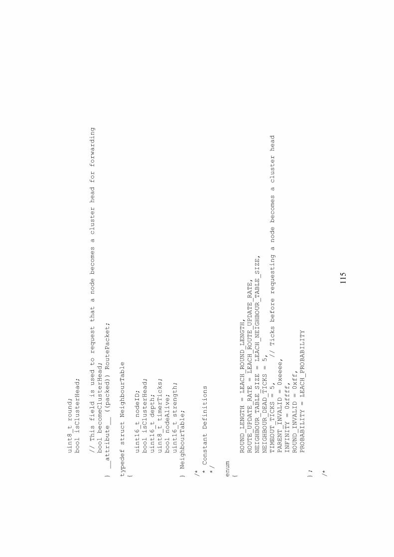
11
5
uint8_t round;
bool isClusterHead;
// This field is used to request that a node becomes a cluster head for forwarding
bool becomeClusterHead;
} __attribute__ ((packed)) RoutePacket;
typedef struct NeighbourTable
{
uint16_t nodeID;
bool isClusterHead;
uint16_t depth;
uint8_t timerTicks;
bool nodeAlive;
uint16_t strength;
} NeighbourTable;
/*
* Constant Definitions
*/
enum
{
ROUND_LENGTH = LEACH_ROUND_LENGTH,
ROUTE_UPDATE_RATE = LEACH_ROUTE_UPDATE_RATE,
NEIGHBOUR_TABLE_SIZE = LEACH_NEIGHBOUR_TABLE_SIZE,
NEIGHBOUR_DEAD_TICKS = 5,
TIMEOUT_TICKS = 5,
// Ticks before requesting a node becomes a cluster head
PARENT_INVALID = 0xeeee,
INFINITY = 0xffff,
ROUND_INVALID = 0xff,
PROBABILITY = LEACH_PROBABILITY
};
/*
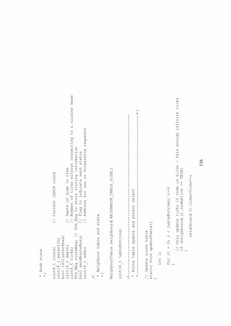
11
6
* Node state
*/
uint8_t round;
// Current LEACH round
uint16_t parentID;
bool isClusterHead;
uint16_t depth;
// Depth of node in tree
uint8_t ticks;
// Number of ticks without connecting to a cluster head
TOS_Msg routeMsg; // TOS_Msg to store routing information
bool sendRouteBusy;
// Flag to indicate send status
uint16_t addr;
// Address for use in forwarding requests
/*
* Neighbour table and state
*/
NeighbourTable neighbours[NEIGHBOUR_TABLE_SIZE];
uint16_t tableEntries;
/*---------------------------------------------------------------------
* Route table update and parent select
*---------------------------------------------------------------------*/
// Update route table
static void updateTable()
{
int i;
for (i = 0; i < tableEntries; i++)
{
// Only update ticks if node is alive - this avoids infinite ticks
if (neighbours[i].nodeAlive == TRUE)
{
neighbours[i].timerTicks++;
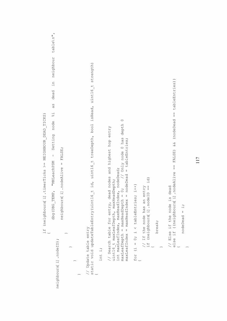
11
7
if (neighbours[i].timerTicks >= NEIGHBOUR_DEAD_TICKS)
{
dbg(DBG_TEMP, "MHLeachPSM - Setting node %i as dead in neighbour table\n",
neighbours[i].nodeID);
neighbours[i].nodeAlive = FALSE;
}
}
}
}
// Update table entry
static void updateTableEntry(uint16_t id, uint16_t treeDepth, bool isHead, uint16_t strength)
{
int i;
// Search table for entry, dead nodes and highest hop entry
uint16_t maxLeafDepth, maxHeadDepth;
int maxLeafIndex, maxHeadIndex, nodeDead;
maxLeafDepth = maxHeadDepth = 0;
// Only node 0 has depth 0
maxLeafIndex = maxHeadIndex = nodeDead = tableEntries;
for (i = 0; i < tableEntries; i++)
{
// If the node has an entry
if (neighbours[i].nodeID == id)
{
break;
}
// Else if the node is dead
else if ((neighbours[i].nodeAlive == FALSE) && (nodeDead == tableEntries))
{
nodeDead = i;
}
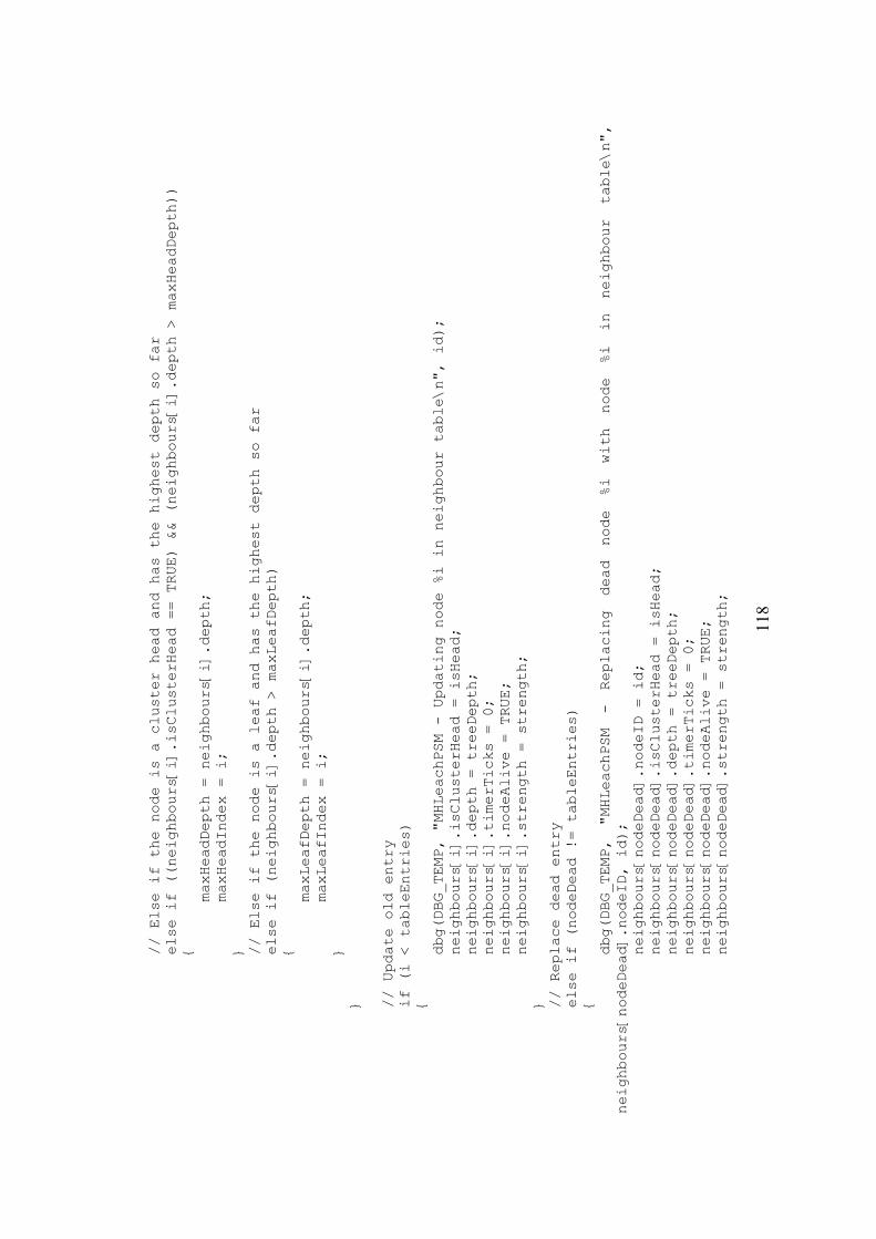
11
8
// Else if the node is a cluster head and has the highest depth so far
else if ((neighbours[i].isClusterHead == TRUE) && (neighbours[i].depth > maxHeadDepth))
{
maxHeadDepth = neighbours[i].depth;
maxHeadIndex = i;
}
// Else if the node is a leaf and has the highest depth so far
else if (neighbours[i].depth > maxLeafDepth)
{
maxLeafDepth = neighbours[i].depth;
maxLeafIndex = i;
}
}
// Update old entry
if (i < tableEntries)
{
dbg(DBG_TEMP, "MHLeachPSM - Updating node %i in neighbour table\n", id);
neighbours[i].isClusterHead = isHead;
neighbours[i].depth = treeDepth;
neighbours[i].timerTicks = 0;
neighbours[i].nodeAlive = TRUE;
neighbours[i].strength = strength;
}
// Replace dead entry
else if (nodeDead != tableEntries)
{
dbg(DBG_TEMP, "MHLeachPSM - Replacing dead node %i with node %i in neighbour table\n",
neighbours[nodeDead].nodeID, id);
neighbours[nodeDead].nodeID = id;
neighbours[nodeDead].isClusterHead = isHead;
neighbours[nodeDead].depth = treeDepth;
neighbours[nodeDead].timerTicks = 0;
neighbours[nodeDead].nodeAlive = TRUE;
neighbours[nodeDead].strength = strength;
11
9
}
// If there is space in the table for a new node
else if (tableEntries < NEIGHBOUR_TABLE_SIZE)
{
dbg(DBG_TEMP, "MHLeachPSM - Adding node %i to neighbour table\n", id);
neighbours[tableEntries].nodeID = id;
neighbours[tableEntries].isClusterHead = isHead;
neighbours[tableEntries].depth = treeDepth;
neighbours[tableEntries].timerTicks = 0;
neighbours[tableEntries].nodeAlive = TRUE;
neighbours[tableEntries++].strength = strength;
}
// Replace leaf node with cluster head node
else if ((isHead == TRUE) && (maxLeafIndex != tableEntries))
{
dbg(DBG_TEMP, "MHLeachPSM - Replacing leaf node %i with cluster head %i in neighbour table\n",
neighbours[maxLeafIndex].nodeID, id);
neighbours[maxLeafIndex].nodeID = id;
neighbours[maxLeafIndex].isClusterHead = isHead;
neighbours[maxLeafIndex].depth = treeDepth;
neighbours[maxLeafIndex].timerTicks = 0;
neighbours[maxLeafIndex].nodeAlive = TRUE;
neighbours[maxLeafIndex].strength = strength;
}
// Replace leaf node with leaf node of lower depth
else if ((maxLeafIndex != tableEntries) && (maxLeafDepth > treeDepth))
{
dbg(DBG_TEMP, "MHLeachPSM - Replacing leaf node %i with leaf node %i in neighbour table\n",
neighbours[maxLeafIndex].nodeID, id);
neighbours[maxLeafIndex].nodeID = id;
neighbours[maxLeafIndex].isClusterHead = isHead;
neighbours[maxLeafIndex].depth = treeDepth;
neighbours[maxLeafIndex].timerTicks = 0;
neighbours[maxLeafIndex].nodeAlive = TRUE;
neighbours[maxLeafIndex].strength = strength;
12
0
}
// Replace cluster head with cluster head closer to base station
else if ((isHead == TRUE) && (maxHeadIndex != tableEntries) && (maxHeadDepth > treeDepth))
{
dbg(DBG_TEMP, "MHLeachPSM - Replacing cluster head %i with cluster head %i in neighbour
table\n", neighbours[maxHeadIndex].nodeID, id);
neighbours[maxHeadIndex].nodeID = id;
neighbours[maxHeadIndex].isClusterHead = isHead;
neighbours[maxHeadIndex].depth = treeDepth;
neighbours[maxHeadIndex].timerTicks = 0;
neighbours[maxHeadIndex].nodeAlive = TRUE;
neighbours[maxHeadIndex].strength = strength;
}
}
// Select parent
static void selectParent()
{
int i;
uint16_t minLeafDepth, minHeadDepth;
int minLeafIndex, minHeadIndex;
ticks++;
minLeafDepth = minHeadDepth = INFINITY;
minLeafIndex = minHeadIndex = tableEntries;
for (i = 0; i < tableEntries; i++)
{
// If node is a cluster head and has the lowest depth
if ((neighbours[i].isClusterHead == TRUE) && (neighbours[i].depth < minHeadDepth))
{
minHeadDepth = neighbours[i].depth;
minHeadIndex = i;
}
// Else if node is a leaf and has the lowest leaf depth
else if (neighbours[i].depth < minLeafDepth)
12
1
{
minLeafDepth = neighbours[i].depth;
minLeafIndex = i;
}
}
// Choose the lowest depth cluster head
if (minHeadIndex != tableEntries)
{
parentID = neighbours[minHeadIndex].nodeID;
depth = neighbours[minHeadIndex].depth + 1;
ticks = 0;
dbg(DBG_TEMP, "MHLeachPSM - New parent selected (ID: %i)\n", parentID);
return;
}
// If timeout has occurred request forwarding from connected leaf node
else if (ticks >= TIMEOUT_TICKS)
{
// Ask a node to become a cluster head every TIMEOUT_TICKS if a suitable node exists;
if (minLeafIndex != tableEntries)
{
atomic addr = neighbours[minLeafIndex].nodeID;
}
ticks = 0; // Set ticks to 0 to restart timeout
}
parentID = PARENT_INVALID;
dbg(DBG_TEMP, "MHLeachPSM - Could not select new parent\n");
depth = INFINITY;
}
/*---------------------------------------------------------------------
* Round Control
*---------------------------------------------------------------------*/
12
2
// Get next round
static void nextRound()
{
round = (round + 1) % ROUND_INVALID;
}
// As round lengths are long accept r as new round if it isn't the current round or previous round
static bool isNewRound(uint8_t r)
{
// Node is advertising invalid round
if (r == ROUND_INVALID)
{
return FALSE;
}
// This node hasn't got a valid round yet
else if (round == ROUND_INVALID)
{
return TRUE;
}
else
{
uint8_t previous;
if (round == 0)
{
previous = ROUND_INVALID - 1;
}
else
{
previous = round--;
}
if ((r != round) && (r != previous))
{
return TRUE;
12
3
}
else
{
return FALSE;
}
}
}
/*---------------------------------------------------------------------
* Route advertisement
*---------------------------------------------------------------------*/
task void advertise()
{
RoutePacket *pRP = (RoutePacket *) &routeMsg.data[0];
uint8_t length = sizeof(RoutePacket);
// If busy sending don't send again
if (sendRouteBusy == TRUE)
{
return;
}
pRP->addr = addr;
atomic addr = TOS_BCAST_ADDR;
pRP->nodeID = TOS_LOCAL_ADDRESS;
pRP->depth = depth;
pRP->round = round;
pRP->isClusterHead = isClusterHead;
// Set fields for forwarding request
if (pRP->addr != TOS_BCAST_ADDR)
{
12
4
dbg(DBG_TEMP, "MHLeachPSM - Requesting node %i become a cluster head\n", pRP->addr);
pRP->becomeClusterHead = TRUE;
}
else
{
pRP->becomeClusterHead = FALSE;
}
// Send message
if (call SendMsg.send(TOS_BCAST_ADDR, length, &routeMsg) == SUCCESS)
{
// Toggle red LED to indicate transmit (Tx)
atomic
{
call Leds.redToggle();
}
dbg(DBG_TEMP, "MHLeachPSM - Advertising presence (Cluster Head: %i)\n", (int) isClusterHead);
atomic sendRouteBusy = TRUE;
}
}
/*---------------------------------------------------------------------
* Initialisation and code to start a new round
*---------------------------------------------------------------------*/
static void init()
{
tableEntries = 0;
ticks = 0;
addr = TOS_BCAST_ADDR;
// Normal route packet - no forwarding request
if (TOS_LOCAL_ADDRESS == BASE_STATION_ADDRESS)
{
round = 0;
12
5
parentID = TOS_UART_ADDR;
isClusterHead = TRUE;
depth = 0;
}
else
{
round = ROUND_INVALID;
parentID = PARENT_INVALID;
isClusterHead = FALSE;
depth = INFINITY;
}
}
// Start new round
static void startNewRound(uint8_t r)
{
// Decide on cluster had status
uint16_t probability = ((uint16_t) PROBABILITY) * (0xffff / 100);
uint16_t randNo = call Random.rand();
bool clusterStatus = randNo < probability;
dbg(DBG_TEMP, "MHLeachPSM - Round %i started (Cluster Head: %i)\n", r, (int) clusterStatus);
atomic
{
round = r;
ticks = 0;
tableEntries = 0;
parentID = PARENT_INVALID;
depth = INFINITY;
addr = TOS_BCAST_ADDR;
isClusterHead = clusterStatus;
}
}
12
6
/*---------------------------------------------------------------------
* Provided Interface Commands
*---------------------------------------------------------------------*/
/*
* StdControl
*/
command result_t StdControl.init()
{
init();
return call Random.init();
}
command result_t StdControl.start()
{
// Start round timer on base station
if (TOS_LOCAL_ADDRESS == BASE_STATION_ADDRESS)
{
call RoundTimer.start(TIMER_REPEAT, ROUND_LENGTH);
}
return call StatusTimer.start(TIMER_REPEAT, ROUTE_UPDATE_RATE);
}
command result_t StdControl.stop()
{
call RoundTimer.stop();
return call StatusTimer.stop();
}
/*
* RouteSelect
*/

12
7
// If parent is valid a route exists
command bool RouteSelect.isActive()
{
if (parentID != PARENT_INVALID)
{
return TRUE;
}
return FALSE;
}
// Select route
command result_t RouteSelect.selectRoute(TOS_MsgPtr msg, uint8_t id)
{
MHMessage *pMHMsg = (MHMessage *) &msg->data[0];
// If packet has been generated by local node
if ((pMHMsg->originNode == TOS_LOCAL_ADDRESS) &&
(pMHMsg->hopCount == 0))
{
if (parentID != PARENT_INVALID)
{
dbg(DBG_TEMP, "MHLeachPSM - Routing to node %i\n", parentID);
msg->addr = parentID;
return SUCCESS;
}
}
else
{
// Set fields for forwarding if node is a cluster head
if ((isClusterHead == TRUE) && (parentID != PARENT_INVALID))
{
pMHMsg->sendingNode = TOS_LOCAL_ADDRESS;
pMHMsg->hopCount++;
dbg(DBG_TEMP, "MHLeachPSM - Routing to node %i\n", parentID);
msg->addr = parentID;
12
8
return SUCCESS;
}
}
dbg(DBG_TEMP, "MHLeachPSM - Could not select route\n");
return FAIL;
}
// Initilise routing fields for new packet
command result_t RouteSelect.initializeFields(TOS_MsgPtr msg, uint8_t id)
{
MHMessage *pMHMsg = (MHMessage *) &msg->data[0];
pMHMsg->originNode = pMHMsg->sendingNode = TOS_LOCAL_ADDRESS;
pMHMsg->hopCount = 0;
return SUCCESS;
}
/*---------------------------------------------------------------------
* Used Interface Events
*---------------------------------------------------------------------*/
// Event fires when base station is to change round
event result_t RoundTimer.fired()
{
dbg(DBG_TEMP, "MHLeachPSM - Round Timer fired\n");
nextRound();
return SUCCESS;
}
// Event fires to indicate that node must advertise presence
event result_t StatusTimer.fired()
{
if ((TOS_LOCAL_ADDRESS != BASE_STATION_ADDRESS) && (round != ROUND_INVALID))
{
12
9
updateTable();
selectParent();
}
post advertise();
return SUCCESS;
}
// Event fires when message is received
event TOS_MsgPtr ReceiveMsg.receive(TOS_MsgPtr m)
{
// Toggle red LED to indicate receive (Rx)
atomic
{
call Leds.redToggle();
}
// Base station doesn't need to know about any other node
if (TOS_LOCAL_ADDRESS != BASE_STATION_ADDRESS)
{
RoutePacket *pRP = (RoutePacket *) m->data;
// Ignore messages when round is invalid
if (pRP->round != ROUND_INVALID)
{
// Start new round if its a new round
if (isNewRound(pRP->round) == TRUE)
{
startNewRound(pRP->round);
}
// If the packet is a forwarding request for this node
else if (pRP->addr == TOS_LOCAL_ADDRESS)
{
isClusterHead = pRP->becomeClusterHead;
13
0
if (pRP->becomeClusterHead == TRUE)
{
dbg(DBG_TEMP, "MHLeachPSM - Becoming cluster head at request of node %i\n",
pRP->nodeID);
}
}
dbg(DBG_TEMP,
"MHLeachPSM
-
Received
advert
(Origin
ID:
%i,
Cluster
Head:
%i,
Depth: %i)\n", pRP->nodeID, (int) pRP->isClusterHead, pRP->depth);
updateTableEntry(pRP->nodeID, pRP->depth, pRP->isClusterHead, m->strength);
}
}
return m;
}
// Event fires when sending is done
event result_t SendMsg.sendDone(TOS_MsgPtr msg, result_t success)
{
atomic sendRouteBusy = FALSE;
return SUCCESS;
}
}
13
1
App
endi
x B
– S
imul
atio
n
Sim
ulat
or T
est R
un S
hell
Scri
pt
#!/bin/bash
export DBG=usr1
rm -rf build
echo ----------------------------
echo - Beginning Simulation Run -
echo ----------------------------
echo
echo Test 1 of 11
echo ------------
echo
echo Protocol: Flooding
echo Motes: 10
echo
unset PFLAGS
export PFLAGS='-DFLOODING -DSIM=10'
make pc
./build/pc/main.exe -a=random -rf=/opt/tinyos-1.x/apps/TempMonitor/topology.nss -t=1900 10
> ./Results/test1.out
echo
echo Test 1 Done!
rm -rf build
echo
echo Test 2 of 11
echo ------------
echo

13
2
echo Protocol: Gossiping
echo Motes: 10
echo
unset PFLAGS
export PFLAGS='-DGOSSIPING -DSIM=10'
make pc
./build/pc/main.exe -a=random -rf=/opt/tinyos-1.x/apps/TempMonitor/topology.nss -t=1900 10
> ./Results/test2.out
echo
echo Test 2 Done!
rm -rf build
echo
echo Test 3 of 11
echo ------------
echo
echo Protocol: LEACH
echo Motes: 10
echo Probability: 25%
echo
unset PFLAGS
export PFLAGS='-DLEACH -DLEACH_PROBABILITY=25 -DSIM=10'
make pc
./build/pc/main.exe -a=random -rf=/opt/tinyos-1.x/apps/TempMonitor/topology.nss -t=1900 10
> ./Results/test3.out
echo
echo Test 3 Done!
rm -rf build
echo
echo Test 4 of 11
echo ------------
echo
echo Protocol: Flooding
echo Motes: 25
13
3
echo
unset PFLAGS
export PFLAGS='-DFLOODING -DSIM=25'
make pc
./build/pc/main.exe -a=random -rf=/opt/tinyos-1.x/apps/TempMonitor/topology.nss -t=1900 25
> ./Results/test4.out
echo
echo Test 4 Done!
rm -rf build
echo
echo Test 5 of 11
echo ------------
echo
echo Protocol: Gossiping
echo Motes: 25
echo
unset PFLAGS
export PFLAGS='-DGOSSIPING -DSIM=25'
make pc
./build/pc/main.exe -a=random -rf=/opt/tinyos-1.x/apps/TempMonitor/topology.nss -t=1900 25
> ./Results/test5.out
echo
echo Test 5 Done!
rm -rf build
echo
echo Test 6 of 11
echo ------------
echo
echo Protocol: LEACH
echo Motes: 25
echo Probability: 25%
echo
unset PFLAGS
13
4
export PFLAGS='-DLEACH -DLEACH_PROBABILITY=25 -DSIM=25'
make pc
./build/pc/main.exe -a=random -rf=/opt/tinyos-1.x/apps/TempMonitor/topology.nss -t=1900 25
> ./Results/test6.out
echo
echo Test 6 Done!
rm -rf build
echo
echo Test 7 of 11
echo ------------
echo
echo Protocol: Flooding
echo Motes: 50
echo
unset PFLAGS
export PFLAGS='-DFLOODING -DSIM=50'
make pc
./build/pc/main.exe -a=random -rf=/opt/tinyos-1.x/apps/TempMonitor/topology.nss -t=1900 50
> ./Results/test7.out
echo
echo Test 7 Done!
rm -rf build
echo
echo Test 8 of 11
echo ------------
echo
echo Protocol: Gossiping
echo Motes: 50
echo
unset PFLAGS
export PFLAGS='-DGOSSIPING -DSIM=50'
make pc
13
5
./build/pc/main.exe -a=random -rf=/opt/tinyos-1.x/apps/TempMonitor/topology.nss -t=1900 50
> ./Results/test8.out
echo
echo Test 8 Done!
rm -rf build
echo
echo Test 9 of 11
echo ------------
echo
echo Protocol: LEACH
echo Motes: 50
echo Probability: 25%
echo
unset PFLAGS
export PFLAGS='-DLEACH -DLEACH_PROBABILITY=25 -DSIM=50'
make pc
./build/pc/main.exe -a=random -rf=/opt/tinyos-1.x/apps/TempMonitor/topology.nss -t=1900 50
> ./Results/test9.out
echo
echo Test 9 Done!
rm -rf build
echo
echo Test 10 of 11
echo -------------
echo
echo Protocol: LEACH
echo Motes: 50
echo Probability: 10%
echo
unset PFLAGS
export PFLAGS='-DLEACH -DLEACH_PROBABILITY=10 -DSIM=50'
make pc
13
6
./build/pc/main.exe -a=random -rf=/opt/tinyos-1.x/apps/TempMonitor/topology.nss -t=1900 50
> ./Results/test10.out
echo
echo Test 10 Done!
rm -rf build
echo
echo Test 11 of 11
echo -------------
echo
echo Protocol: LEACH
echo Motes: 50
echo Probability: 50%
echo
unset PFLAGS
export PFLAGS='-DLEACH -DLEACH_PROBABILITY=50 -DSIM=50'
make pc
./build/pc/main.exe -a=random -rf=/opt/tinyos-1.x/apps/TempMonitor/topology.nss -t=1900 50
> ./Results/test11.out
echo
echo Test 11 Done!
rm -rf build
echo

13
7
Proc
esse
d Si
mul
ator
Out
put
For e
ach
sim
ulat
or te
st tw
o ta
bles
are
pre
sent
ed. T
he fi
rst t
able
giv
es th
e nu
mbe
r of p
acke
ts se
nt, r
ecei
ved
and
forw
arde
d by
a n
ode
as w
ell
as th
e po
wer
it u
sed
durin
g th
e si
mul
ator
run.
The
seco
nd ta
ble
was
mai
ntai
ned
by th
e ba
se s
tatio
n an
d gi
ves
the
num
ber o
f pac
kets
rece
ived
by
the
base
sta
tion
from
a n
ode
as
wel
l as t
imin
g da
ta a
bout
the
pack
ets r
ecei
ved
from
that
nod
e.
Tes
t 1
Nod
e Se
nt
Rec
eive
d Fo
rwar
ded
Pow
er
Use
d
0 35
9 14
349
3076
39
003
1
359
1252
9 25
28
3371
9
2 35
9 92
69
2524
27
187
3
357
1198
8 25
20
3260
7
4 35
8 14
214
2667
37
503
5
359
1133
5 27
25
3192
2
6 35
8 12
490
2522
33
620
7
359
9255
25
23
2715
6
8 35
8 11
989
2524
32
624
9
358
1422
5 26
70
3753
4
Nod
e R
ecei
ved
Bes
t H
op B
est
Wor
st
Hop
Wor
st
Ave
rage
H
op
Ave
rage
0
359
0 0
0 0
0 0
1 35
9 10
10
-2
2 -2
2 67
7 67
7 2
359
10
10
4964
49
64
794
794
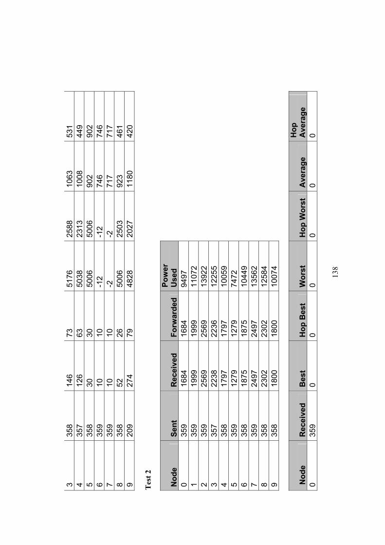
13
8
3 35
8 14
6 73
51
76
2588
10
63
531
4 35
7 12
6 63
50
38
2313
10
08
449
5 35
8 30
30
50
06
5006
90
2 90
2 6
359
10
10
-12
-12
746
746
7 35
9 10
10
-2
-2
71
7 71
7 8
358
52
26
5006
25
03
923
461
9 20
9 27
4 79
48
28
2027
11
80
420
Tes
t 2
Nod
e Se
nt
Rec
eive
d Fo
rwar
ded
Pow
er
Use
d
0 35
9 16
84
1684
94
97
1
359
1999
19
99
1107
2
2 35
9 25
69
2569
13
922
3
357
2238
22
36
1225
5
4 35
8 17
97
1797
10
059
5
359
1279
12
79
7472
6 35
8 18
75
1875
10
449
7
359
2497
24
97
1356
2
8 35
8 23
02
2302
12
584
9
358
1800
18
00
1007
4
Nod
e R
ecei
ved
Bes
t H
op B
est
Wor
st
Hop
Wor
st
Ave
rage
H
op
Ave
rage
0
359
0 0
0 0
0 0
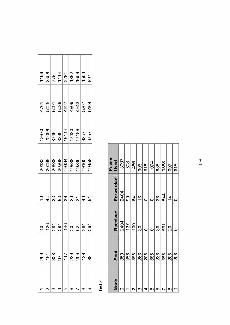
13
9
1 29
9 10
10
20
132
1267
0 47
61
1199
2
181
126
44
2009
8 20
098
5025
23
58
3 32
8 28
4 33
20
538
8746
50
91
775
4 97
28
4 63
20
368
8330
50
86
1114
5
117
146
39
1943
4 18
114
4627
32
91
6 23
9 20
20
19
688
1748
0 46
09
1862
7
206
62
31
1928
6 17
186
4643
16
59
8 12
9 26
4 40
19
160
9257
52
07
1503
9
88
294
51
1945
8 67
57
5164
89
7 T
est 3
Nod
e Se
nt
Rec
eive
d Fo
rwar
ded
Pow
er
Use
d
0 35
9 24
04
2404
13
097
1
358
127
90
1598
2 35
8 10
0 64
14
66
3
266
30
16
906
4
206
0 0
618
5
358
0 0
1074
6 23
6 36
36
88
8
7 35
8 59
1 54
4 38
88
8
205
20
14
697
9
206
0 0
618
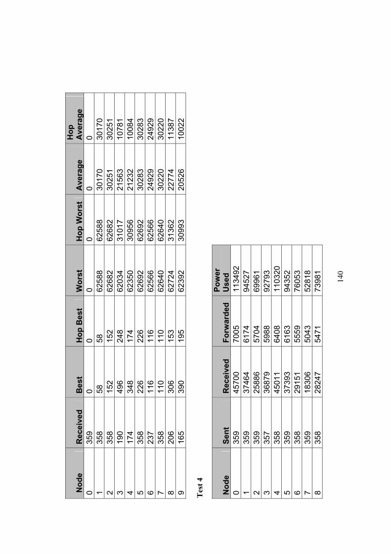
14
0
Nod
e R
ecei
ved
Bes
t H
op B
est
Wor
st
Hop
Wor
st
Ave
rage
H
op
Ave
rage
0
359
0 0
0 0
0 0
1 35
8 58
58
62
588
6258
8 30
170
3017
0 2
358
152
152
6268
2 62
682
3025
1 30
251
3 19
0 49
6 24
8 62
034
3101
7 21
563
1078
1 4
174
348
174
6235
0 30
956
2123
2 10
084
5 35
8 22
6 22
6 62
692
6269
2 30
283
3028
3 6
237
116
116
6256
6 62
566
2492
9 24
929
7 35
8 11
0 11
0 62
640
6264
0 30
220
3022
0 8
206
306
153
6272
4 31
362
2277
4 11
387
9 16
5 39
0 19
5 62
392
3099
3 20
526
1002
2 T
est 4
Nod
e Se
nt
Rec
eive
d Fo
rwar
ded
Pow
er
Use
d
0 35
9 45
700
7005
11
3492
1 35
9 37
464
6174
94
527
2
359
2588
6 57
04
6996
1
3 35
7 36
879
5988
92
793
4
358
4501
1 64
08
1103
20
5
359
3739
3 61
63
9435
2
6 35
8 29
151
5559
76
053
7
359
1830
6 50
43
5281
8
8 35
8 28
247
5471
73
981
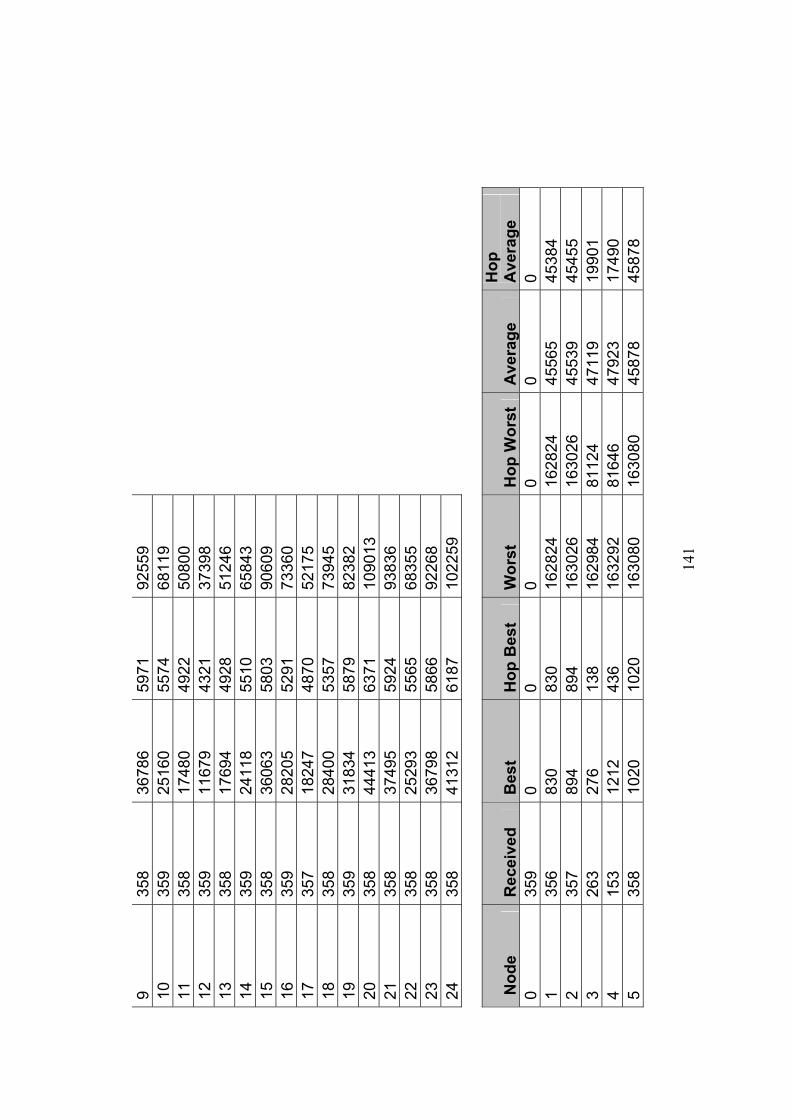
14
1
9 35
8 36
786
5971
92
559
10
35
9 25
160
5574
68
119
11
35
8 17
480
4922
50
800
12
35
9 11
679
4321
37
398
13
35
8 17
694
4928
51
246
14
35
9 24
118
5510
65
843
15
35
8 36
063
5803
90
609
16
35
9 28
205
5291
73
360
17
35
7 18
247
4870
52
175
18
35
8 28
400
5357
73
945
19
35
9 31
834
5879
82
382
20
35
8 44
413
6371
10
9013
21
358
3749
5 59
24
9383
6
22
358
2529
3 55
65
6835
5
23
358
3679
8 58
66
9226
8
24
358
4131
2 61
87
1022
59
Nod
e R
ecei
ved
Bes
t H
op B
est
Wor
st
Hop
Wor
st
Ave
rage
H
op
Ave
rage
0
359
0 0
0 0
0 0
1 35
6 83
0 83
0 16
2824
16
2824
45
565
4538
4 2
357
894
894
1630
26
1630
26
4553
9 45
455
3 26
3 27
6 13
8 16
2984
81
124
4711
9 19
901
4 15
3 12
12
436
1632
92
8164
6 47
923
1749
0 5
358
1020
10
20
1630
80
1630
80
4587
8 45
878
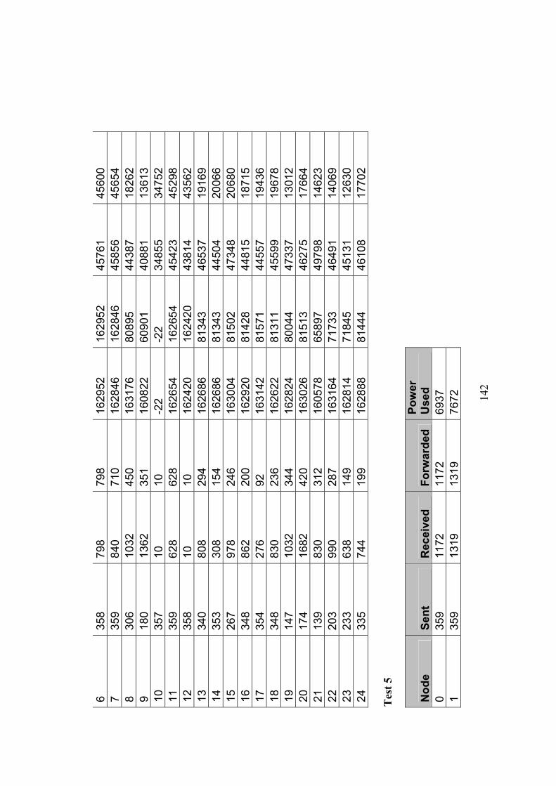
14
2
6 35
8 79
8 79
8 16
2952
16
2952
45
761
4560
0 7
359
840
710
1628
46
1628
46
4585
6 45
654
8 30
6 10
32
450
1631
76
8089
5 44
387
1826
2 9
180
1362
35
1 16
0822
60
901
4088
1 13
613
10
357
10
10
-22
-22
3485
5 34
752
11
359
628
628
1626
54
1626
54
4542
3 45
298
12
358
10
10
1624
20
1624
20
4381
4 43
562
13
340
808
294
1626
86
8134
3 46
537
1916
9 14
35
3 30
8 15
4 16
2686
81
343
4450
4 20
066
15
267
978
246
1630
04
8150
2 47
348
2068
0 16
34
8 86
2 20
0 16
2920
81
428
4481
5 18
715
17
354
276
92
1631
42
8157
1 44
557
1943
6 18
34
8 83
0 23
6 16
2622
81
311
4559
9 19
678
19
147
1032
34
4 16
2824
80
044
4733
7 13
012
20
174
1682
42
0 16
3026
81
513
4627
5 17
664
21
139
830
312
1605
78
6589
7 49
798
1462
3 22
20
3 99
0 28
7 16
3164
71
733
4649
1 14
069
23
233
638
149
1628
14
7184
5 45
131
1263
0 24
33
5 74
4 19
9 16
2888
81
444
4610
8 17
702
Tes
t 5
Nod
e Se
nt
Rec
eive
d Fo
rwar
ded
Pow
er
Use
d
0 35
9 11
72
1172
69
37
1
359
1319
13
19
7672
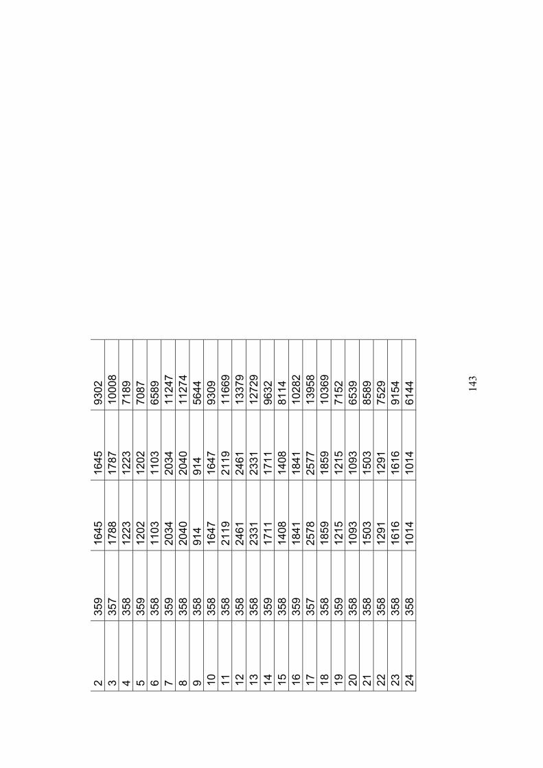
14
3
2 35
9 16
45
1645
93
02
3
357
1788
17
87
1000
8
4 35
8 12
23
1223
71
89
5
359
1202
12
02
7087
6 35
8 11
03
1103
65
89
7
359
2034
20
34
1124
7
8 35
8 20
40
2040
11
274
9
358
914
914
5644
10
358
1647
16
47
9309
11
358
2119
21
19
1166
9
12
358
2461
24
61
1337
9
13
358
2331
23
31
1272
9
14
359
1711
17
11
9632
15
358
1408
14
08
8114
16
359
1841
18
41
1028
2
17
357
2578
25
77
1395
8
18
358
1859
18
59
1036
9
19
359
1215
12
15
7152
20
358
1093
10
93
6539
21
358
1503
15
03
8589
22
358
1291
12
91
7529
23
358
1616
16
16
9154
24
358
1014
10
14
6144

14
4
Nod
e R
ecei
ved
Bes
t H
op B
est
Wor
st
Hop
Wor
st
Ave
rage
H
op
Ave
rage
0
359
0 0
0 0
0 0
1 73
23
2 42
83
94
7468
24
95
1485
2
74
442
91
1221
8 79
88
2783
13
54
3 63
30
8 31
87
10
2903
25
52
408
4 33
55
8 55
71
16
1779
26
41
556
5 33
44
2 10
4 10
972
1097
2 25
41
1957
6
61
336
84
1009
4 88
74
2617
18
20
7 70
40
0 77
12
080
1208
0 27
15
1318
8
49
442
68
1235
6 24
71
2724
64
4 9
19
484
62
8600
35
47
3155
64
4 10
66
10
10
-2
2 -2
2 62
3 26
7 11
11
9 24
2 39
11
858
8028
25
81
725
12
49
74
37
1170
0 58
50
2845
10
59
13
48
600
49
8772
23
75
2604
56
0 14
33
15
8 34
80
18
2672
21
28
482
15
62
420
58
8212
24
75
2791
60
2 16
68
23
2 43
88
86
2765
23
88
409
17
115
148
28
1228
6 26
77
2849
28
9 18
26
14
6 73
88
78
2812
29
29
667
19
3 43
2 21
6 36
32
1210
17
03
562
20
27
380
80
5894
14
63
1806
57
5 21
6
540
93
3940
65
6 19
55
291
22
14
656
82
4614
23
07
2243
71
0
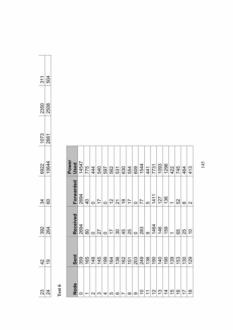
14
5
23
42
392
34
6922
10
73
2350
31
1 24
19
26
4 60
10
644
2661
25
08
504
Tes
t 6
Nod
e Se
nt
Rec
eive
d Fo
rwar
ded
Pow
er
Use
d
0 35
9 26
94
2694
14
547
1
165
80
40
775
2
148
0 0
444
3
145
27
17
540
4
199
0 0
597
5
164
17
12
562
6
136
30
21
531
7
162
45
18
630
8
151
25
17
554
9
203
0 0
609
10
24
9 28
3 77
15
44
11
13
6 9
5 44
1
12
190
1464
14
11
7731
13
140
146
127
1093
14
190
159
136
1296
15
139
1 1
422
16
15
3 65
52
74
5
17
130
25
8 46
4
18
129
10
2 41
3
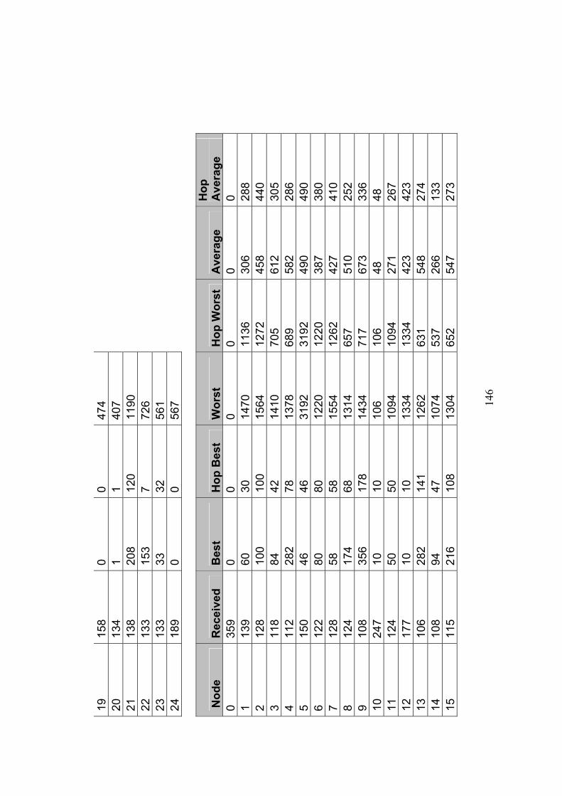
14
6
19
158
0 0
474
20
13
4 1
1 40
7
21
138
208
120
1190
22
133
153
7 72
6
23
133
33
32
561
24
18
9 0
0 56
7
Nod
e R
ecei
ved
Bes
t H
op B
est
Wor
st
Hop
Wor
st
Ave
rage
H
op
Ave
rage
0
359
0 0
0 0
0 0
1 13
9 60
30
14
70
1136
30
6 28
8 2
128
100
100
1564
12
72
458
440
3 11
8 84
42
14
10
705
612
305
4 11
2 28
2 78
13
78
689
582
286
5 15
0 46
46
31
92
3192
49
0 49
0 6
122
80
80
1220
12
20
387
380
7 12
8 58
58
15
54
1262
42
7 41
0 8
124
174
68
1314
65
7 51
0 25
2 9
108
356
178
1434
71
7 67
3 33
6 10
24
7 10
10
10
6 10
6 48
48
11
12
4 50
50
10
94
1094
27
1 26
7 12
17
7 10
10
13
34
1334
42
3 42
3 13
10
6 28
2 14
1 12
62
631
548
274
14
108
94
47
1074
53
7 26
6 13
3 15
11
5 21
6 10
8 13
04
652
547
273
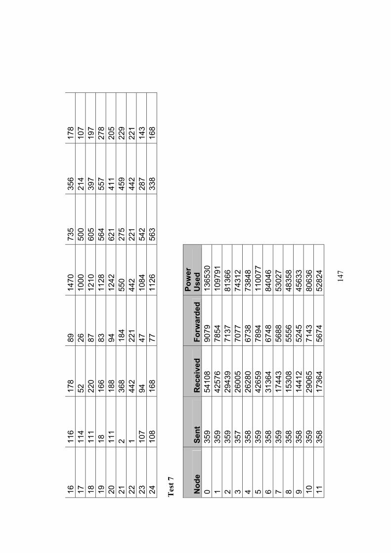
14
7
16
116
178
89
1470
73
5 35
6 17
8 17
11
4 52
26
10
00
500
214
107
18
111
220
87
1210
60
5 39
7 19
7 19
18
16
6 83
11
28
564
557
278
20
111
188
94
1242
62
1 41
1 20
5 21
2
368
184
550
275
459
229
22
1 44
2 22
1 44
2 22
1 44
2 22
1 23
10
7 94
47
10
84
542
287
143
24
108
168
77
1126
56
3 33
8 16
8 T
est 7
Nod
e Se
nt
Rec
eive
d Fo
rwar
ded
Pow
er
Use
d
0 35
9 54
108
9079
13
6530
1 35
9 42
576
7854
10
9791
2 35
9 29
439
7137
81
366
3
357
2600
5 70
77
7431
2
4 35
8 26
280
6738
73
848
5
359
4265
9 78
94
1100
77
6
358
3136
4 67
48
8404
6
7 35
9 17
443
5688
53
027
8
358
1530
8 55
56
4835
8
9 35
8 14
412
5245
45
633
10
35
9 29
065
7143
80
636
11
35
8 17
364
5674
52
824
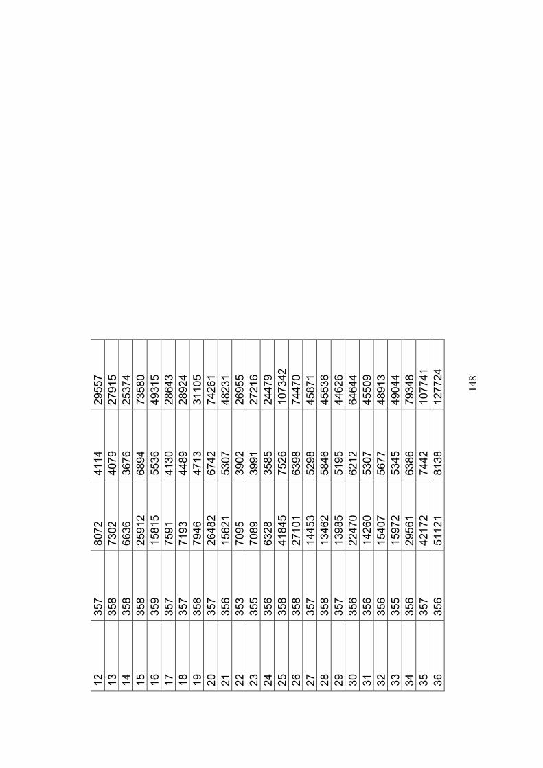
14
8
12
357
8072
41
14
2955
7
13
358
7302
40
79
2791
5
14
358
6636
36
76
2537
4
15
358
2591
2 68
94
7358
0
16
359
1581
5 55
36
4931
5
17
357
7591
41
30
2864
3
18
357
7193
44
89
2892
4
19
358
7946
47
13
3110
5
20
357
2648
2 67
42
7426
1
21
356
1562
1 53
07
4823
1
22
353
7095
39
02
2695
5
23
355
7089
39
91
2721
6
24
356
6328
35
85
2447
9
25
358
4184
5 75
26
1073
42
26
35
8 27
101
6398
74
470
27
35
7 14
453
5298
45
871
28
35
8 13
462
5846
45
536
29
35
7 13
985
5195
44
626
30
35
6 22
470
6212
64
644
31
35
6 14
260
5307
45
509
32
35
6 15
407
5677
48
913
33
35
5 15
972
5345
49
044
34
35
6 29
561
6386
79
348
35
35
7 42
172
7442
10
7741
36
356
5112
1 81
38
1277
24
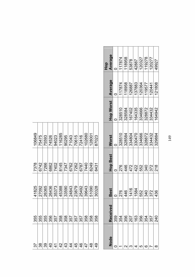
14
9
37
355
4182
5 73
78
1068
49
38
35
5 27
092
6742
75
475
39
35
5 26
365
7266
75
593
40
35
6 26
436
6862
74
526
41
35
7 35
373
7402
94
023
42
35
8 45
388
8145
11
6285
43
358
3359
0 73
47
9029
5
44
357
2484
3 67
62
7104
3
45
357
2387
9 72
62
7061
5
46
357
2549
2 67
87
7241
6
47
358
3964
3 74
40
1026
80
48
35
8 51
090
8249
12
8001
49
358
3032
8 84
31
8702
3
Nod
e R
ecei
ved
Bes
t H
op B
est
Wor
st
Hop
Wor
st
Ave
rage
H
op
Ave
rage
0
359
0 0
0 0
0 0
1 35
4 27
6 27
6 32
8510
32
8510
11
7874
11
7874
2
356
446
446
3285
84
3285
84
1189
58
1189
58
3 20
7 14
16
472
3348
04
1674
02
1268
87
5387
8 4
163
1584
42
2 33
0470
16
4335
13
7883
42
887
5 35
6 55
2 55
2 33
4666
33
4666
12
0364
12
0327
6
354
340
340
3288
72
3288
72
1195
77
1192
78
7 35
7 37
2 37
2 33
4432
33
4432
12
0441
12
0277
8
240
436
218
3298
84
1649
42
1218
08
4992
7

15
0
9 21
2 77
6 25
4 33
5392
15
0432
13
1487
38
873
10
355
10
10
-22
-22
9704
4 97
044
11
355
138
138
3282
76
3282
76
1180
54
1176
14
12
353
10
10
3279
78
3279
78
1173
17
1173
17
13
293
606
303
3306
94
1653
47
1194
85
4582
8 14
26
8 20
02
504
3363
30
1656
40
1313
19
4345
7 15
21
0 62
6 31
3 33
7350
16
8675
12
6210
55
894
16
296
670
223
3363
62
1669
82
1292
59
5514
6 17
31
6 53
2 17
7 33
7160
16
7158
12
2242
49
912
18
130
1340
26
8 33
5382
16
4099
12
8998
44
939
19
86
4570
91
4 33
4870
12
2263
14
2201
31
692
20
156
1232
40
7 33
7532
16
4324
13
5645
44
818
21
177
350
116
3356
70
1489
03
1361
12
3748
7 22
24
2 16
40
410
3369
58
1621
80
1344
21
4160
0 23
18
2 37
40
374
3392
40
1580
76
1442
75
3126
3 24
15
9 27
04
450
3338
16
1015
02
1320
83
2358
1 25
13
7 38
34
577
3316
96
9982
5 12
6235
30
447
26
150
3268
30
7 33
5892
10
7660
13
3342
30
710
27
218
2298
76
6 33
1174
11
0391
12
7295
32
063
28
123
1362
17
0 33
3456
90
680
1305
11
2541
9 29
10
1 69
90
998
3360
74
6721
4 14
2519
22
306
30
123
6326
79
0 32
8518
77
160
1414
10
2280
3 31
11
4 30
02
428
3296
90
8228
7 14
8138
24
592
32
144
2340
58
5 33
7308
10
9392
14
1671
25
149
33
215
2898
57
9 33
8280
10
7717
13
6062
33
811
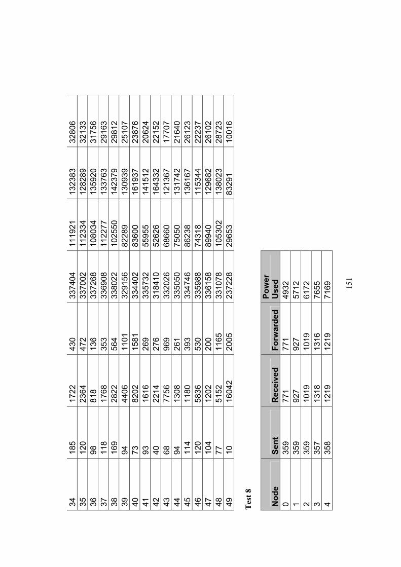
15
1
34
185
1722
43
0 33
7404
11
1921
13
2383
32
806
35
120
2364
47
2 33
7002
11
2334
12
8289
32
133
36
98
818
136
3372
68
1080
34
1359
20
3175
6 37
11
8 17
68
353
3369
08
1122
77
1337
63
2916
3 38
16
9 28
22
564
3380
22
1025
50
1423
79
2981
2 39
94
44
06
1101
32
9156
82
289
1309
39
2510
7 40
73
82
02
1581
33
4402
83
600
1619
37
2387
6 41
93
16
16
269
3357
32
5595
5 14
1512
20
624
42
40
2214
27
6 31
8410
52
626
1643
32
2215
2 43
68
77
56
969
3320
26
6866
0 12
1367
17
707
44
94
1308
26
1 33
5050
75
050
1317
42
2164
0 45
11
4 11
80
393
3347
46
8623
8 13
6167
26
123
46
120
5836
53
0 33
5988
74
318
1153
44
2223
7 47
10
4 12
02
200
3361
58
8994
0 12
9682
26
102
48
77
5152
11
65
3310
78
1053
02
1380
23
2872
3 49
10
16
042
2005
23
7228
29
653
8329
1 10
016
Tes
t 8
Nod
e Se
nt
Rec
eive
d Fo
rwar
ded
Pow
er
Use
d
0 35
9 77
1 77
1 49
32
1
359
927
927
5712
2 35
9 10
19
1019
61
72
3
357
1318
13
16
7655
4 35
8 12
19
1219
71
69
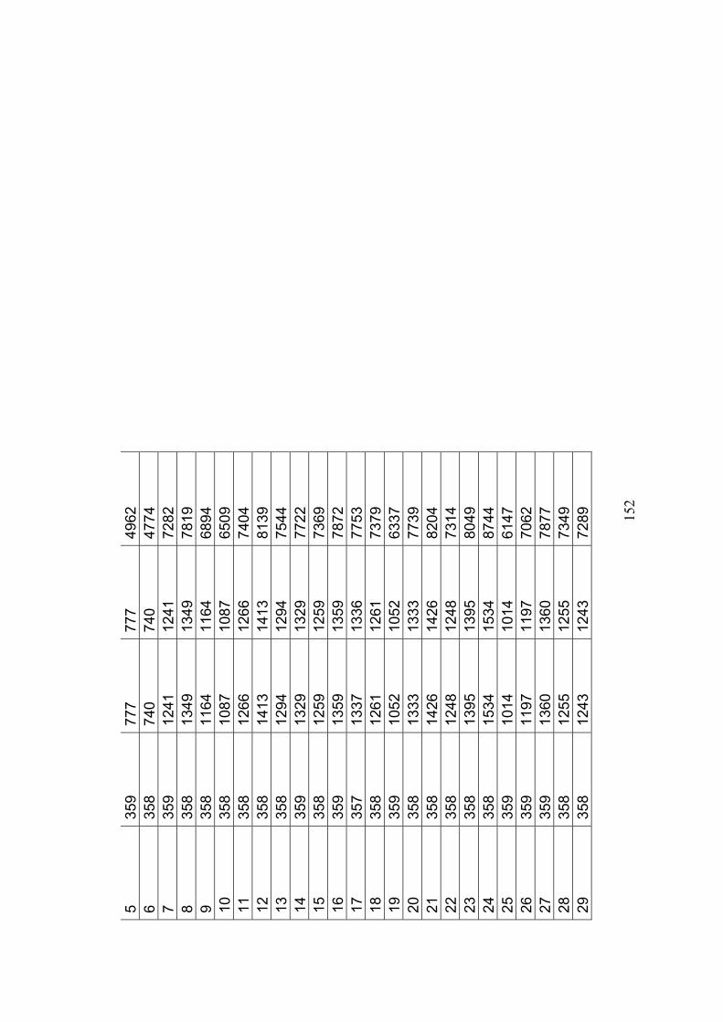
15
2
5 35
9 77
7 77
7 49
62
6
358
740
740
4774
7 35
9 12
41
1241
72
82
8
358
1349
13
49
7819
9 35
8 11
64
1164
68
94
10
35
8 10
87
1087
65
09
11
35
8 12
66
1266
74
04
12
35
8 14
13
1413
81
39
13
35
8 12
94
1294
75
44
14
35
9 13
29
1329
77
22
15
35
8 12
59
1259
73
69
16
35
9 13
59
1359
78
72
17
35
7 13
37
1336
77
53
18
35
8 12
61
1261
73
79
19
35
9 10
52
1052
63
37
20
35
8 13
33
1333
77
39
21
35
8 14
26
1426
82
04
22
35
8 12
48
1248
73
14
23
35
8 13
95
1395
80
49
24
35
8 15
34
1534
87
44
25
35
9 10
14
1014
61
47
26
35
9 11
97
1197
70
62
27
35
9 13
60
1360
78
77
28
35
8 12
55
1255
73
49
29
35
8 12
43
1243
72
89
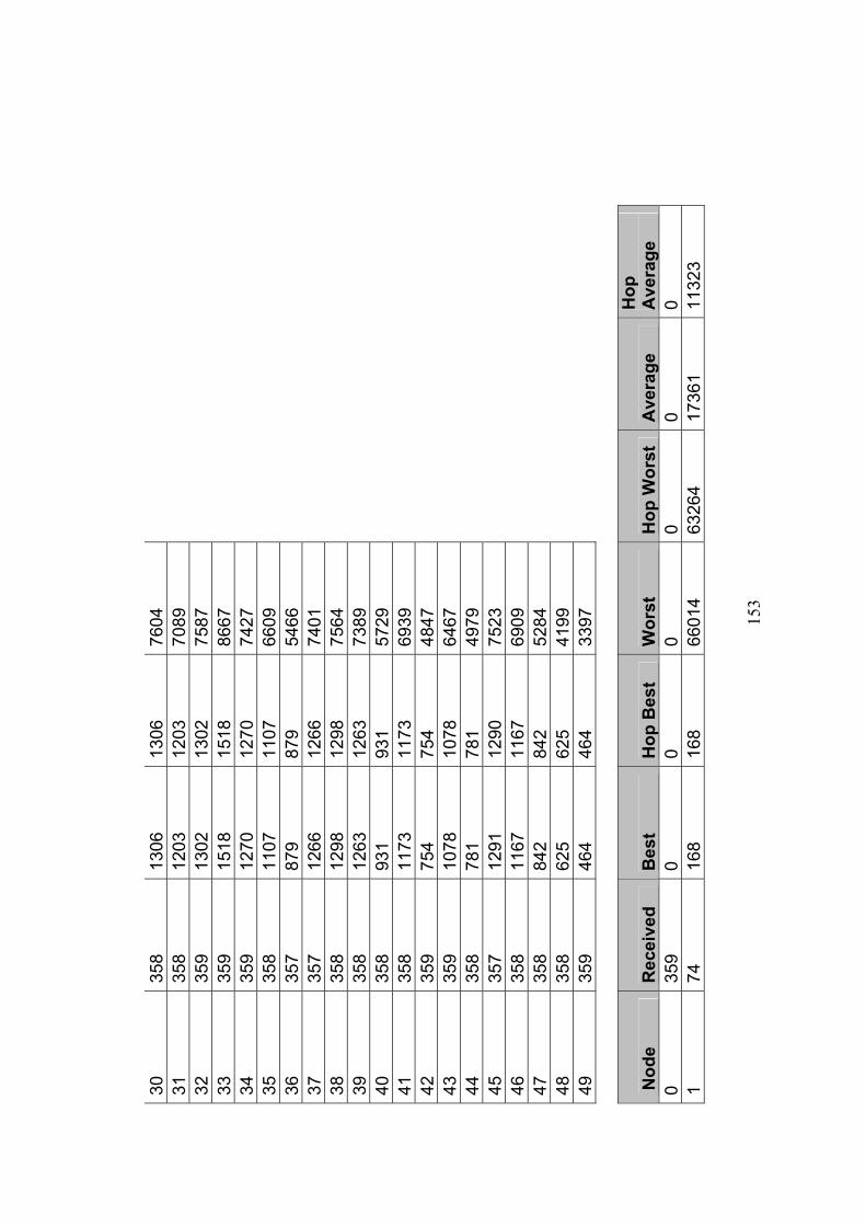
15
3
30
358
1306
13
06
7604
31
358
1203
12
03
7089
32
359
1302
13
02
7587
33
359
1518
15
18
8667
34
359
1270
12
70
7427
35
358
1107
11
07
6609
36
357
879
879
5466
37
357
1266
12
66
7401
38
358
1298
12
98
7564
39
358
1263
12
63
7389
40
358
931
931
5729
41
358
1173
11
73
6939
42
359
754
754
4847
43
359
1078
10
78
6467
44
358
781
781
4979
45
357
1291
12
90
7523
46
358
1167
11
67
6909
47
358
842
842
5284
48
358
625
625
4199
49
359
464
464
3397
Nod
e R
ecei
ved
Bes
t H
op B
est
Wor
st
Hop
Wor
st
Ave
rage
H
op
Ave
rage
0
359
0 0
0 0
0 0
1 74
16
8 16
8 66
014
6326
4 17
361
1132
3
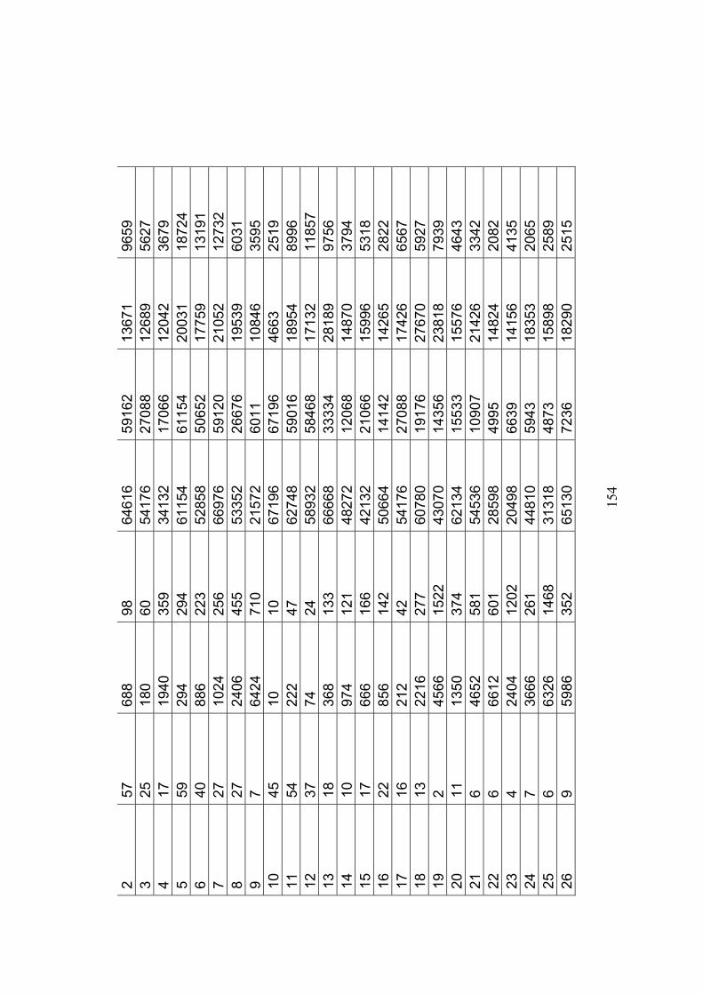
15
4
2 57
68
8 98
64
616
5916
2 13
671
9659
3
25
180
60
5417
6 27
088
1268
9 56
27
4 17
19
40
359
3413
2 17
066
1204
2 36
79
5 59
29
4 29
4 61
154
6115
4 20
031
1872
4 6
40
886
223
5285
8 50
652
1775
9 13
191
7 27
10
24
256
6697
6 59
120
2105
2 12
732
8 27
24
06
455
5335
2 26
676
1953
9 60
31
9 7
6424
71
0 21
572
6011
10
846
3595
10
45
10
10
67
196
6719
6 46
63
2519
11
54
22
2 47
62
748
5901
6 18
954
8996
12
37
74
24
58
932
5846
8 17
132
1185
7 13
18
36
8 13
3 66
668
3333
4 28
189
9756
14
10
97
4 12
1 48
272
1206
8 14
870
3794
15
17
66
6 16
6 42
132
2106
6 15
996
5318
16
22
85
6 14
2 50
664
1414
2 14
265
2822
17
16
21
2 42
54
176
2708
8 17
426
6567
18
13
22
16
277
6078
0 19
176
2767
0 59
27
19
2 45
66
1522
43
070
1435
6 23
818
7939
20
11
13
50
374
6213
4 15
533
1557
6 46
43
21
6 46
52
581
5453
6 10
907
2142
6 33
42
22
6 66
12
601
2859
8 49
95
1482
4 20
82
23
4 24
04
1202
20
498
6639
14
156
4135
24
7
3666
26
1 44
810
5943
18
353
2065
25
6
6326
14
68
3131
8 48
73
1589
8 25
89
26
9 59
86
352
6513
0 72
36
1829
0 25
15
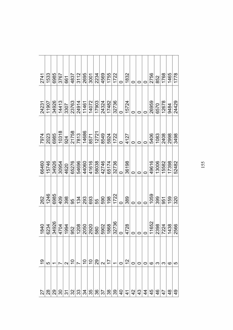
15
5
27
19
1840
26
2 66
460
7974
24
231
2741
28
5
6234
12
46
1574
6 20
23
1190
7 15
33
29
1 34
926
6985
34
926
6985
34
926
6985
30
7
4704
40
9 30
954
1031
8 14
413
3767
31
2
1994
39
8 46
20
924
3307
66
1 32
10
95
2 95
65
276
2175
8 23
763
4837
33
7
1208
13
4 54
696
7813
24
914
3112
34
10
20
50
293
4406
0 14
686
1146
1 26
95
35
10
2920
69
3 41
616
8571
14
072
3001
36
29
58
0 55
58
038
1272
1 17
903
2234
37
2
5902
59
0 42
746
8549
24
324
4569
38
17
18
68
198
6517
4 59
24
1748
2 17
55
39
1 32
736
1722
32
736
1722
32
736
1722
40
0
0 0
0 0
0 0
41
12
4728
38
9 36
198
4127
15
724
1832
42
0
0 0
0 0
0 0
43
0 0
0 0
0 0
0 44
0
0 0
0 0
0 0
45
6 11
652
1059
49
616
5406
26
959
2756
46
3
2398
39
9 13
006
1083
65
70
852
47
3 72
24
951
1558
2 24
08
1267
8 17
68
48
6 14
38
159
1739
8 29
98
9484
14
65
49
5 25
66
320
5248
2 34
98
2442
9 17
78
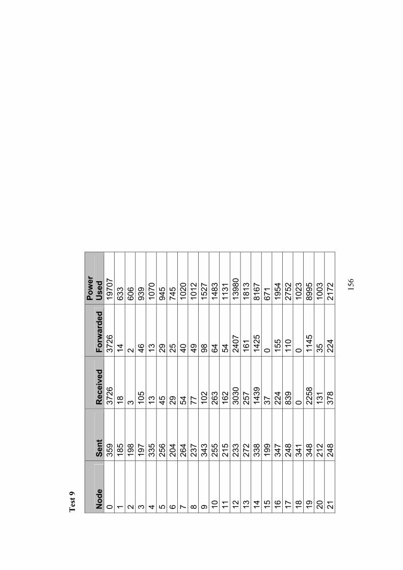
15
6
Tes
t 9
Nod
e Se
nt
Rec
eive
d Fo
rwar
ded
Pow
er
Use
d
0 35
9 37
26
3726
19
707
1
185
18
14
633
2
198
3 2
606
3
197
105
46
939
4
335
13
13
1070
5 25
6 45
29
94
5
6 20
4 29
25
74
5
7 26
4 54
40
10
20
8
237
77
49
1012
9 34
3 10
2 98
15
27
10
25
5 26
3 64
14
83
11
21
5 16
2 54
11
31
12
23
3 30
30
2407
13
980
13
27
2 25
7 16
1 18
13
14
33
8 14
39
1425
81
67
15
19
9 37
0
671
16
34
7 22
4 15
5 19
54
17
24
8 83
9 11
0 27
52
18
34
1 0
0 10
23
19
34
8 22
58
1145
89
95
20
21
2 13
1 35
10
03
21
24
8 37
8 22
4 21
72
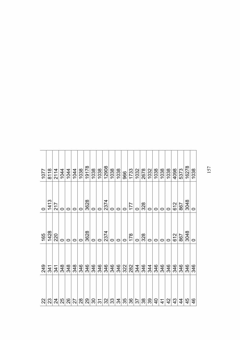
15
7
22
249
165
0 10
77
23
34
1 14
28
1413
81
18
24
34
1 22
0 21
7 21
14
25
34
8 0
0 10
44
26
34
8 0
0 10
44
27
34
8 0
0 10
44
28
34
6 0
0 10
38
29
34
6 36
28
3628
19
178
30
34
6 0
0 10
38
31
34
6 0
0 10
38
32
34
6 23
74
2374
12
908
33
34
6 0
0 10
38
34
34
6 0
0 10
38
35
32
2 0
0 96
6
36
282
178
177
1733
37
344
0 0
1032
38
346
328
328
2678
39
344
0 0
1032
40
346
0 0
1038
41
346
0 0
1038
42
346
0 0
1038
43
346
612
612
4098
44
346
867
867
5373
45
346
3048
30
48
1627
8
46
346
0 0
1038
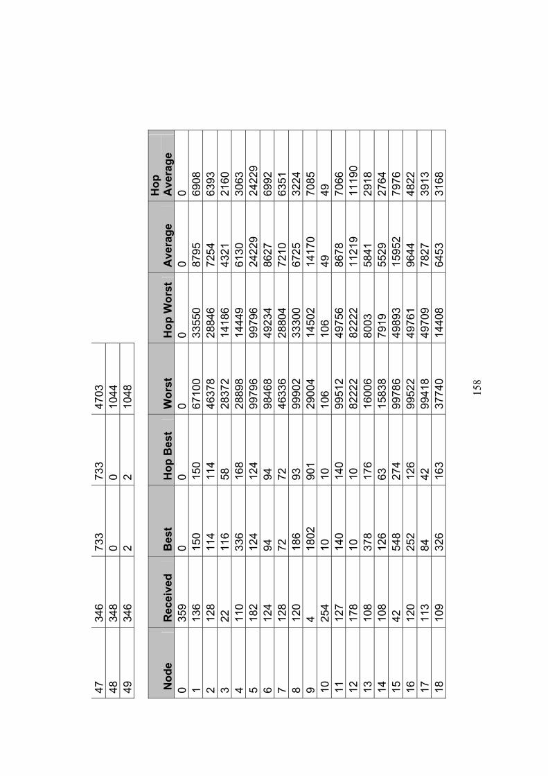
15
8
47
346
733
733
4703
48
348
0 0
1044
49
346
2 2
1048
Nod
e R
ecei
ved
Bes
t H
op B
est
Wor
st
Hop
Wor
st
Ave
rage
H
op
Ave
rage
0
359
0 0
0 0
0 0
1 13
6 15
0 15
0 67
100
3355
0 87
95
6908
2
128
114
114
4637
8 28
846
7254
63
93
3 22
11
6 58
28
372
1418
6 43
21
2160
4
110
336
168
2889
8 14
449
6130
30
63
5 18
2 12
4 12
4 99
796
9979
6 24
229
2422
9 6
124
94
94
9846
8 49
234
8627
69
92
7 12
8 72
72
46
336
2880
4 72
10
6351
8
120
186
93
9990
2 33
300
6725
32
24
9 4
1802
90
1 29
004
1450
2 14
170
7085
10
25
4 10
10
10
6 10
6 49
49
11
12
7 14
0 14
0 99
512
4975
6 86
78
7066
12
17
8 10
10
82
222
8222
2 11
219
1119
0 13
10
8 37
8 17
6 16
006
8003
58
41
2918
14
10
8 12
6 63
15
838
7919
55
29
2764
15
42
54
8 27
4 99
786
4989
3 15
952
7976
16
12
0 25
2 12
6 99
522
4976
1 96
44
4822
17
11
3 84
42
99
418
4970
9 78
27
3913
18
10
9 32
6 16
3 37
740
1440
8 64
53
3168
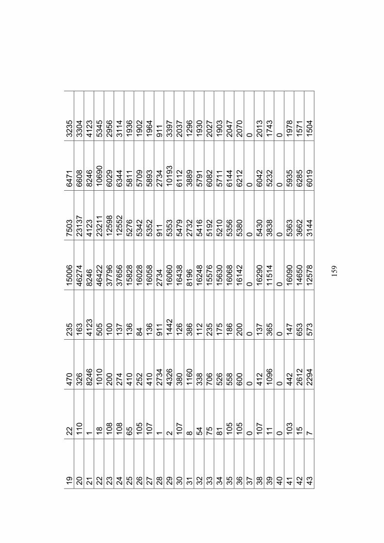
15
9
19
22
470
235
1500
6 75
03
6471
32
35
20
110
326
163
4627
4 23
137
6608
33
04
21
1 82
46
4123
82
46
4123
82
46
4123
22
18
10
10
505
4642
2 23
211
1069
0 53
45
23
108
200
100
3779
6 12
598
6029
29
56
24
108
274
137
3765
6 12
552
6344
31
14
25
65
410
136
1582
8 52
76
5811
19
36
26
105
252
84
1602
8 53
42
5709
19
02
27
107
410
136
1605
8 53
52
5893
19
64
28
1 27
34
911
2734
91
1 27
34
911
29
2 43
26
1442
16
060
5353
10
193
3397
30
10
7 38
0 12
6 16
438
5479
61
12
2037
31
8
1160
38
6 81
96
2732
38
89
1296
32
54
33
8 11
2 16
248
5416
57
91
1930
33
75
70
6 23
5 15
576
5192
60
82
2027
34
81
52
6 17
5 15
630
5210
57
11
1903
35
10
5 55
8 18
6 16
068
5356
61
44
2047
36
10
5 60
0 20
0 16
142
5380
62
12
2070
37
0
0 0
0 0
0 0
38
107
412
137
1629
0 54
30
6042
20
13
39
11
1096
36
5 11
514
3838
52
32
1743
40
0
0 0
0 0
0 0
41
103
442
147
1609
0 53
63
5935
19
78
42
15
2612
65
3 14
650
3662
62
85
1571
43
7
2294
57
3 12
578
3144
60
19
1504
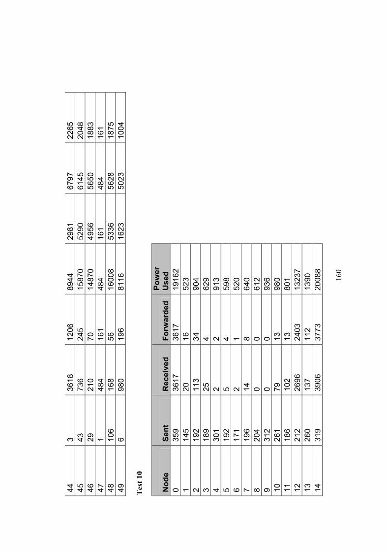
16
0
44
3 36
18
1206
89
44
2981
67
97
2265
45
43
73
6 24
5 15
870
5290
61
45
2048
46
29
21
0 70
14
870
4956
56
50
1883
47
1
484
161
484
161
484
161
48
106
168
56
1600
8 53
36
5628
18
75
49
6 98
0 19
6 81
16
1623
50
23
1004
T
est 1
0
Nod
e Se
nt
Rec
eive
d Fo
rwar
ded
Pow
er
Use
d
0 35
9 36
17
3617
19
162
1
145
20
16
523
2
192
113
34
904
3
189
25
4 62
9
4 30
1 2
2 91
3
5 19
2 5
4 59
8
6 17
1 2
1 52
0
7 19
6 14
8
640
8
204
0 0
612
9
312
0 0
936
10
26
1 79
13
98
0
11
186
102
13
801
12
21
2 26
96
2403
13
237
13
26
0 13
7 11
2 13
90
14
31
9 39
06
3773
20
088
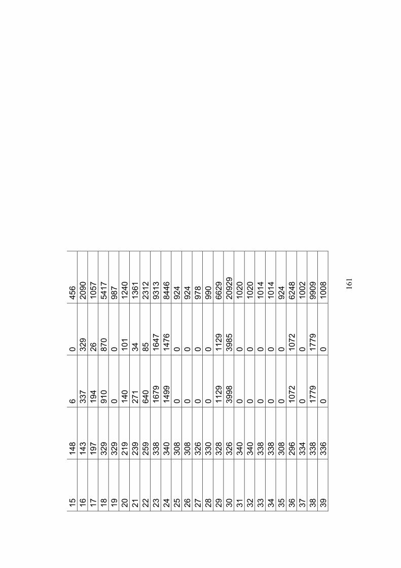
16
1
15
148
6 0
456
16
14
3 33
7 32
9 20
90
17
19
7 19
4 26
10
57
18
32
9 91
0 87
0 54
17
19
32
9 0
0 98
7
20
219
140
101
1240
21
239
271
34
1361
22
259
640
85
2312
23
338
1679
16
47
9313
24
340
1499
14
76
8446
25
308
0 0
924
26
30
8 0
0 92
4
27
326
0 0
978
28
33
0 0
0 99
0
29
328
1129
11
29
6629
30
326
3998
39
85
2092
9
31
340
0 0
1020
32
340
0 0
1020
33
338
0 0
1014
34
338
0 0
1014
35
308
0 0
924
36
29
6 10
72
1072
62
48
37
33
4 0
0 10
02
38
33
8 17
79
1779
99
09
39
33
6 0
0 10
08
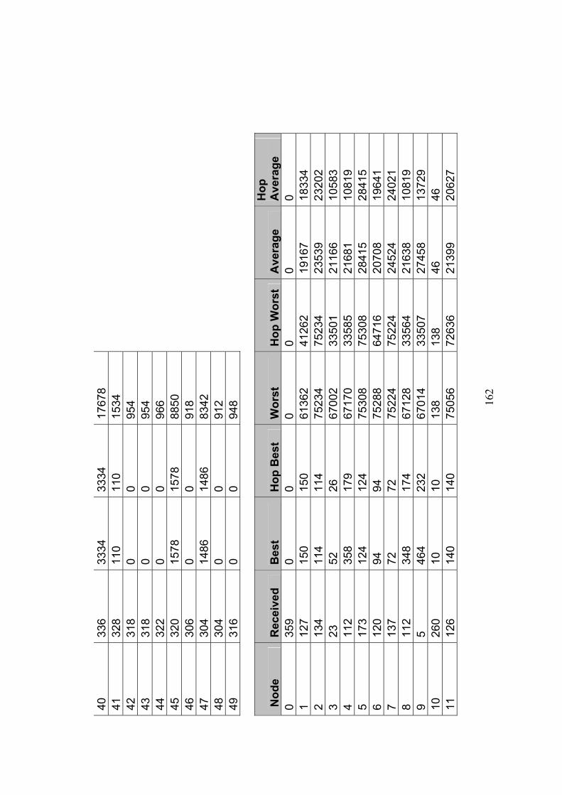
16
2
40
336
3334
33
34
1767
8
41
328
110
110
1534
42
318
0 0
954
43
31
8 0
0 95
4
44
322
0 0
966
45
32
0 15
78
1578
88
50
46
30
6 0
0 91
8
47
304
1486
14
86
8342
48
304
0 0
912
49
31
6 0
0 94
8
Nod
e R
ecei
ved
Bes
t H
op B
est
Wor
st
Hop
Wor
st
Ave
rage
H
op
Ave
rage
0
359
0 0
0 0
0 0
1 12
7 15
0 15
0 61
362
4126
2 19
167
1833
4 2
134
114
114
7523
4 75
234
2353
9 23
202
3 23
52
26
67
002
3350
1 21
166
1058
3 4
112
358
179
6717
0 33
585
2168
1 10
819
5 17
3 12
4 12
4 75
308
7530
8 28
415
2841
5 6
120
94
94
7528
8 64
716
2070
8 19
641
7 13
7 72
72
75
224
7522
4 24
524
2402
1 8
112
348
174
6712
8 33
564
2163
8 10
819
9 5
464
232
6701
4 33
507
2745
8 13
729
10
260
10
10
138
138
46
46
11
126
140
140
7505
6 72
636
2139
9 20
627
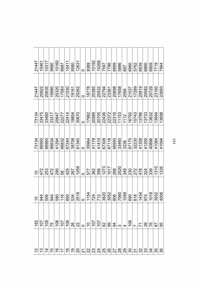
16
3
12
182
10
10
7313
4 73
134
2144
7 21
447
13
107
944
472
6695
0 33
475
2092
2 10
461
14
109
506
253
6696
0 33
480
2063
5 10
317
15
75
944
472
6663
4 33
317
1998
0 99
90
16
108
580
290
4129
4 20
647
2032
0 10
160
17
107
116
58
6683
2 22
277
1758
3 86
87
18
108
850
425
6724
4 22
414
2103
0 10
411
19
26
534
267
3970
8 19
854
1916
1 95
80
20
22
2518
12
59
6134
0 30
670
2526
2 12
631
21
0 0
0 0
0 0
0 22
10
11
54
577
3596
4 17
982
1877
8 93
89
23
107
724
362
4117
8 20
589
2038
5 10
192
24
107
712
356
4141
0 20
705
2053
2 10
266
25
62
3820
12
73
6730
8 22
436
2279
4 75
97
26
99
3052
10
17
6711
8 22
372
2336
1 77
86
27
94
806
268
6695
0 22
316
2069
8 68
99
28
3 75
60
2520
33
460
1115
3 17
658
5886
29
4
1048
34
9 33
36
1112
20
94
697
30
108
690
230
6717
0 16
792
2103
7 69
60
31
7 81
8 27
2 32
230
1074
3 17
289
5762
32
71
14
34
478
4135
8 13
786
2081
9 69
39
33
39
974
324
4120
0 13
733
2058
2 68
60
34
76
1018
33
9 40
896
1363
2 20
729
6909
35
87
39
32
1310
41
084
1369
4 23
160
7719
36
95
40
06
1335
41
094
1369
8 22
693
7564
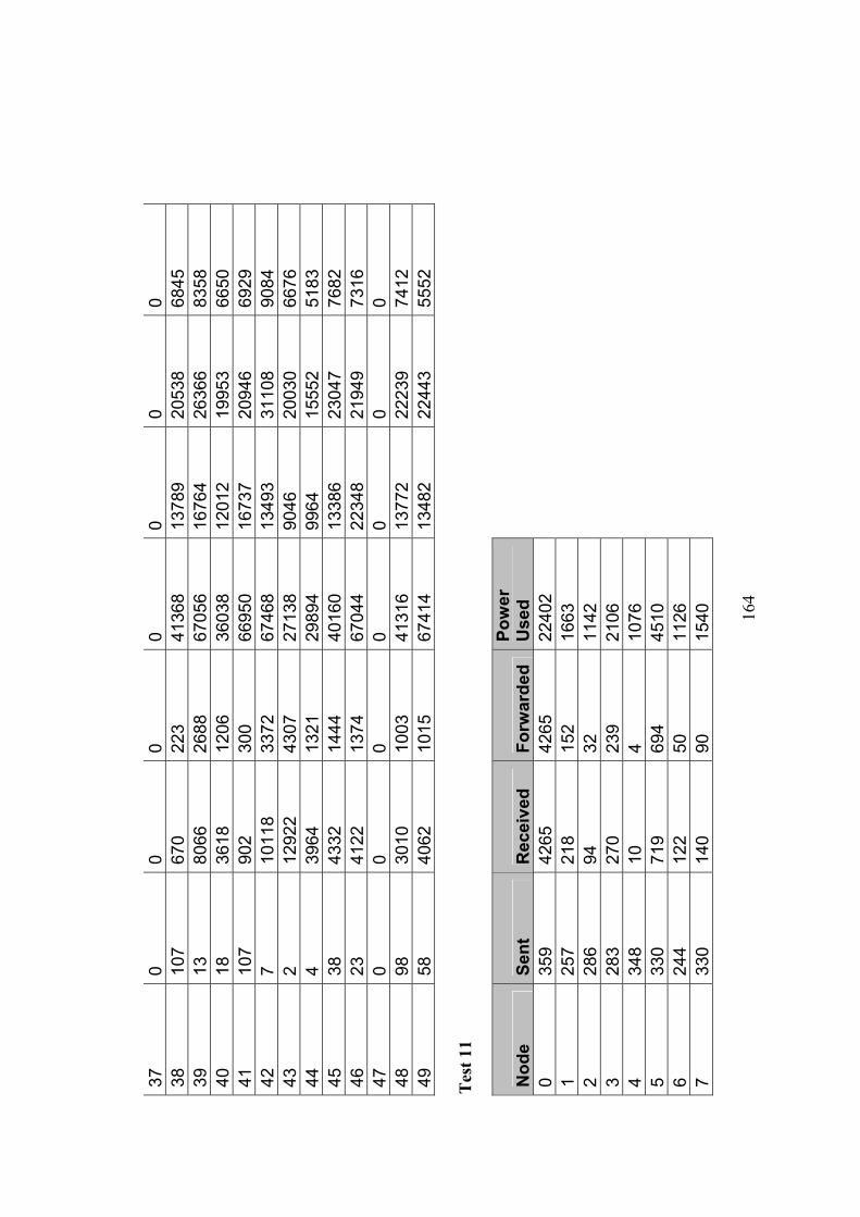
16
4
37
0 0
0 0
0 0
0 38
10
7 67
0 22
3 41
368
1378
9 20
538
6845
39
13
80
66
2688
67
056
1676
4 26
366
8358
40
18
36
18
1206
36
038
1201
2 19
953
6650
41
10
7 90
2 30
0 66
950
1673
7 20
946
6929
42
7
1011
8 33
72
6746
8 13
493
3110
8 90
84
43
2 12
922
4307
27
138
9046
20
030
6676
44
4
3964
13
21
2989
4 99
64
1555
2 51
83
45
38
4332
14
44
4016
0 13
386
2304
7 76
82
46
23
4122
13
74
6704
4 22
348
2194
9 73
16
47
0 0
0 0
0 0
0 48
98
30
10
1003
41
316
1377
2 22
239
7412
49
58
40
62
1015
67
414
1348
2 22
443
5552
T
est 1
1
Nod
e Se
nt
Rec
eive
d Fo
rwar
ded
Pow
er
Use
d
0 35
9 42
65
4265
22
402
1
257
218
152
1663
2 28
6 94
32
11
42
3
283
270
239
2106
4 34
8 10
4
1076
5 33
0 71
9 69
4 45
10
6
244
122
50
1126
7 33
0 14
0 90
15
40
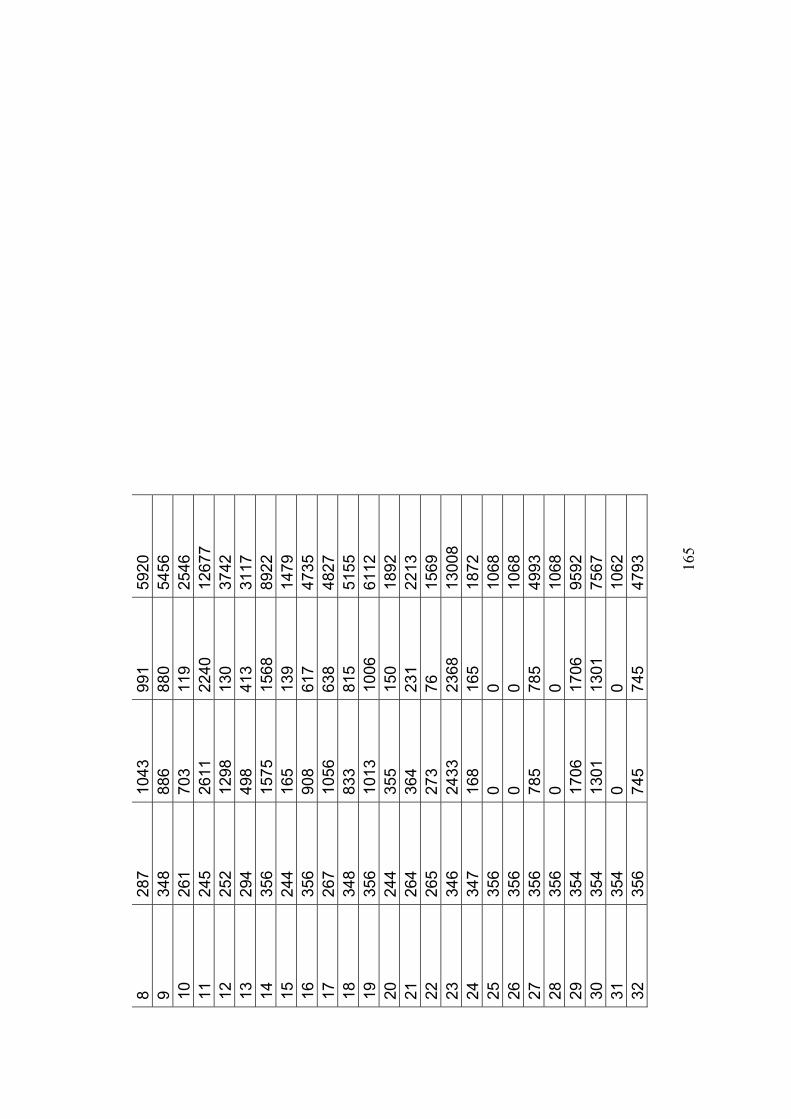
16
5
8 28
7 10
43
991
5920
9 34
8 88
6 88
0 54
56
10
26
1 70
3 11
9 25
46
11
24
5 26
11
2240
12
677
12
25
2 12
98
130
3742
13
294
498
413
3117
14
356
1575
15
68
8922
15
244
165
139
1479
16
356
908
617
4735
17
267
1056
63
8 48
27
18
34
8 83
3 81
5 51
55
19
35
6 10
13
1006
61
12
20
24
4 35
5 15
0 18
92
21
26
4 36
4 23
1 22
13
22
26
5 27
3 76
15
69
23
34
6 24
33
2368
13
008
24
34
7 16
8 16
5 18
72
25
35
6 0
0 10
68
26
35
6 0
0 10
68
27
35
6 78
5 78
5 49
93
28
35
6 0
0 10
68
29
35
4 17
06
1706
95
92
30
35
4 13
01
1301
75
67
31
35
4 0
0 10
62
32
35
6 74
5 74
5 47
93
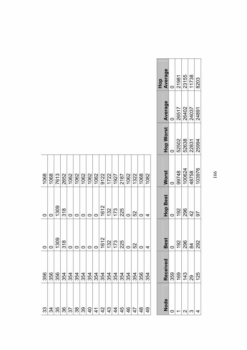
16
6
33
356
0 0
1068
34
356
0 0
1068
35
356
1309
13
09
7613
36
354
318
318
2652
37
354
0 0
1062
38
354
0 0
1062
39
354
0 0
1062
40
354
0 0
1062
41
354
0 0
1062
42
354
1612
16
12
9122
43
354
132
132
1722
44
354
173
173
1927
45
354
225
225
2187
46
354
0 0
1062
47
354
52
52
1322
48
356
0 0
1068
49
354
4 4
1082
Nod
e R
ecei
ved
Bes
t H
op B
est
Wor
st
Hop
Wor
st
Ave
rage
H
op
Ave
rage
0
359
0 0
0 0
0 0
1 16
9 19
2 19
2 99
748
5250
2 26
517
2198
1 2
143
296
296
1006
24
5263
8 26
402
2315
5 3
29
84
42
4875
8 22
831
2403
7 11
738
4 12
5 29
2 97
10
3976
25
994
2489
1 82
03

16
7
5 19
8 30
6 30
6 10
5596
10
5596
37
572
3679
8 6
135
226
226
1037
12
5185
6 27
331
2398
0 7
141
254
254
1005
50
4634
6 26
925
2320
8 8
134
218
109
1039
02
3463
4 27
059
1262
9 9
36
2426
80
8 46
064
1535
4 22
050
7429
10
24
8 10
10
99
750
9975
0 45
3 45
3 11
13
6 19
4 19
4 10
0350
46
114
2683
7 23
468
12
178
10
10
9998
0 99
980
2128
0 21
280
13
116
186
93
4589
4 22
947
2366
0 11
830
14
87
290
96
4609
4 15
364
2341
4 78
78
15
131
342
171
1057
24
5286
2 29
614
1472
1 16
13
5 26
8 13
4 10
0328
50
164
2793
3 13
966
17
128
52
26
9983
0 49
915
1965
6 98
05
18
126
234
117
1036
70
3455
6 26
477
1253
6 19
20
27
6 92
45
422
1514
0 23
026
7803
20
12
8 25
0 12
5 10
3734
50
201
2690
2 13
165
21
3 40
90
2045
82
054
4102
7 38
882
1944
1 22
38
41
32
2066
10
3754
41
048
2982
3 14
223
23
88
1014
50
7 10
0180
33
393
2682
1 12
823
24
120
624
208
1004
14
2510
3 25
282
8327
25
9
3490
11
63
3536
0 11
786
1802
0 60
06
26
95
374
124
4912
8 15
396
2478
5 82
18
27
108
302
100
4601
0 15
336
2392
8 79
75
28
10
196
65
4593
6 15
312
1446
0 48
20
29
28
3680
12
26
8168
6 16
337
2671
8 85
16
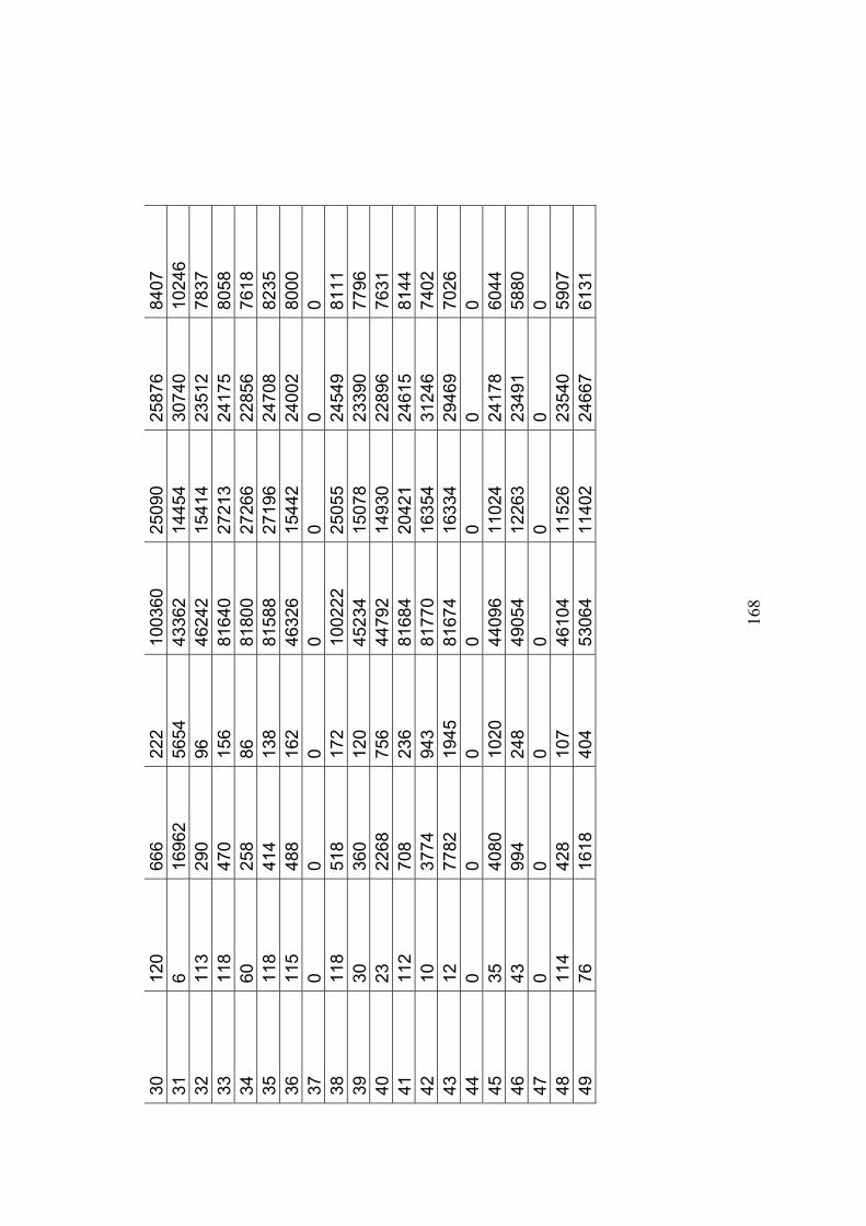
16
8
30
120
666
222
1003
60
2509
0 25
876
8407
31
6
1696
2 56
54
4336
2 14
454
3074
0 10
246
32
113
290
96
4624
2 15
414
2351
2 78
37
33
118
470
156
8164
0 27
213
2417
5 80
58
34
60
258
86
8180
0 27
266
2285
6 76
18
35
118
414
138
8158
8 27
196
2470
8 82
35
36
115
488
162
4632
6 15
442
2400
2 80
00
37
0 0
0 0
0 0
0 38
11
8 51
8 17
2 10
0222
25
055
2454
9 81
11
39
30
360
120
4523
4 15
078
2339
0 77
96
40
23
2268
75
6 44
792
1493
0 22
896
7631
41
11
2 70
8 23
6 81
684
2042
1 24
615
8144
42
10
37
74
943
8177
0 16
354
3124
6 74
02
43
12
7782
19
45
8167
4 16
334
2946
9 70
26
44
0 0
0 0
0 0
0 45
35
40
80
1020
44
096
1102
4 24
178
6044
46
43
99
4 24
8 49
054
1226
3 23
491
5880
47
0
0 0
0 0
0 0
48
114
428
107
4610
4 11
526
2354
0 59
07
49
76
1618
40
4 53
064
1140
2 24
667
6131