Embed Size (px)
Citation preview
570 IEEE/ASME TRANSACTIONS ON MECHATRONICS, VOL. 19, NO. 2, APRIL 2014
An Energy-Saving Pressure-Compensated HydraulicSystem With Electrical Approach
Tao Wang and Qingfeng Wang, Member, IEEE
Abstract—Mobile hydraulic systems are developed toward bet-ter control performance and higher energy efficiency. Pressurecompensators, which govern the pressure drops over the controlorifices, are widely used in multiactuator systems to improve theiroperability. However, additional energy is also dissipated in thecompensators especially under the overrunning load conditions.This paper presents a novel energy-saving system, where the com-pensator is designed as a regeneration device consisting of a hy-draulic motor and an electric generator. Then, hydraulic energycan be regenerated and pressure compensation function is real-ized by adapting the electromagnetic torque of the generator to theload as well. The close-loop control of the generator is designedby effective pressure drop estimation. The proposed energy-savingsystem and controller are implemented on an experimental plat-form of hybrid excavators which is equipped with an electric energystorage device. The experimental results show both good controlperformance and significant energy-saving effect.
Index Terms—Energy saving, hybrid system, hydraulic actuator,pressure compensation, regeneration.
I. INTRODUCTION
IN RECENT years, energy crisis and environmental pollutionhave become more and more serious problems that the world
has to face. A lot of efforts have been spent to save energy andreduce emission in various fields. Hydraulic systems are widelyemployed in industry applications, but they are remarkably inef-ficient with efficiencies ranging from 6 to 40% [1]. Therefore, itis meaningful to exploit the energy-saving potential of hydraulictransmissions.
Developing efficient hydraulic systems is an important ap-proach to save the energy of fluid power, which is usually cate-gorized into two types. One is to match the pump output powerto the desired power and the other is to regenerate the recov-erable energy of actuators such as braking kinetic energy andgravitational potential energy.
In the first type of efficient systems, a typical one is the loadsensing (LS) system which has been widely applied to mobile
Manuscript received July 24, 2012; revised November 8, 2012; acceptedFebruary 21, 2013. Date of publication March 19, 2013; date of current versionFebruary 20, 2014. Recommended by Technical Editor Y. Li. This work wassupported in part by the National Natural Science Foundation of China underGrant 50875233 and in part by the National High Technology Research andDevelopment Program of China under Grant 2010AA044401.
The authors are with the State Key Laboratory of Fluid Power Trans-mission and Control, Zhejiang University, Hangzhou 310027, China (e-mail:[email protected]; [email protected]).
Color versions of one or more of the figures in this paper are available onlineat http://ieeexplore.ieee.org.
Digital Object Identifier 10.1109/TMECH.2013.2250296
hydraulic machines. The basic idea of the LS technique is to con-trol the flow supply via the feedback of the highest loaded pres-sure [2]. However, the LS system is prone to oscillation due tothe feedback control, so its damping and stability should be care-fully checked [3], [4]. In traditional control valves, the meter-inand meter-out orifices are mechanically connected, which re-sults in extra metering losses under some working conditions.A step forward from the LS system with single-spool valves isto decouple the metering control orifices in the valves so as tosave more energy [5], [5]. A pump-controlled system is a furtherone which is more efficient than a throttle governing system be-cause throttle losses are eliminated thoroughly within the mainhydraulic lines. But this system leads to the challenging con-troller design due to the presence of nonlinearity and high-orderdynamic characteristics [7]–[9].
Energy regeneration can be realized through three ap-proaches: cross connection, hydraulic storage, and electricalstorage. Yao and Liu studied an energy-saving electro-hydraulicsystem where a single-rod cylinder is controlled by five indepen-dent cartridge valves [10]–[13]. Four valves constitute an indi-vidual metering system and the extra one governs the connectionof the two chambers of the cylinder for energy recovery. Thehydraulic storage approach is to convert the recoverable energyto hydraulic form, store it in an accumulator, and release it byusing secondary components or auxiliary cylinders [14]–[17].Since a hydraulic accumulator usually requires large installationspace, increasing its energy density will significantly improveits application [18]. In the electrical regeneration system, therecoverable energy is converted to electrical form which canbe directly delivered to any electrical actuators. Thus, it is asuitable energy-saving approach for hybrid or electrical powerdriven hydraulic machines which have been equipped with bat-teries or super capacitors [19]–[22]. However, the controllabilityof hydraulic actuators in large mobile machines such as exca-vators will become worse when they are controlled by the ro-tational speeds of electric generators instead of the openings ofvalves [23].
Good control performance is also an important aspect thathydraulic systems pursue. In one-pump multiactuator systems,pressure compensators are often used to govern the pressuredrops over the control orifices so that the effects of load varia-tions are reduced and different actuators can thereby be operatedalmost without cross talking [6]. However, the disadvantage isthat the pump should supply additional energy consumed inthe use of compensators, especially under the overrunning loadconditions [24].
This paper presents an energy-saving pressure-compensatedhydraulic system which combines a pressure compensator and
1083-4435 © 2013 IEEE. Personal use is permitted, but republication/redistribution requires IEEE permission.See http://www.ieee.org/publications standards/publications/rights/index.html for more information.

WANG AND WANG: AN ENERGY-SAVING PRESSURE-COMPENSATED HYDRAULIC SYSTEM WITH ELECTRICAL APPROACH 571
Fig. 1. Basic idea. (a) Traditional pressure compensator. (b) Proposedstructure.
an electrical regeneration device together. This system can re-alize the functions of pressure compensation and energy regen-eration simultaneously. The recoverable energy, which includesexcess pump supplied and external input such as gravitationalpotential energy, is converted to electrical form and reused whenthere is a requirement. The regeneration device is mainly com-posed of a hydraulic motor and a vector-controlled generator.The pressure drop over the metering orifice is controlled to a rel-atively low level by adapting the electromagnetic torque of thegenerator to the load. A sensorless close-loop controller is de-signed based on the effective pressure drop estimation. Finally,the proposed energy-saving system and controller are tested onan experimental platform of hybrid excavators under variousworking modes. The experimental results show both good con-trol performance and significant energy-saving effect.
The rest of the paper is organized as follows. System schemeis introduced in Section II. Performance analysis is presentedin Section III. Experimental setup and evaluation are given inSection IV, and conclusions are drawn in Section V.
II. SYSTEM SCHEME
A. Configuration
The basic idea of this study is shown in Fig. 1. It aims to realizethe functions of pressure compensation and energy regenerationsimultaneously. In the proposed structure, the traditional reduc-ing valve is replaced with a regeneration device consisting of ahydraulic motor and a coaxially coupled electrical generator.
Fig. 2 shows the schematic diagram of the proposed hydraulicsystem. It can be used in the applications where multiple actu-ators work together. Furthermore, the energy saving is moreconsiderable when the load difference between two actuators islarger. The load condition can be either overrunning or resis-tive, which is determined by the direction and magnitude of theexternal force. The oil supply adopts the highest operated loadthrough shuttle valves and sets the pump pressure to the sum ofthe dominant load pressure and a constant margin. The hydraulicmotor and the electrical generator are used to convert hydraulicenergy to electrical form and provide compensated pressure.To make the system compact and efficient, an axial piston hy-draulic motor and a permanent magnet synchronous generatorare preferable candidates due to their high efficiencies and powerdensities. Batteries and super capacitors are usually employed
Fig. 2. Schematic diagram of the proposed hydraulic system.
Fig. 3. Energy distributions. (a) Resistive load. (b) Overrunning load.
as the common electric energy storage devices. It is relativelyeconomical to apply this system to a hybrid or electrical powerdriven hydraulic machine, for this machine has been equippedwith an electric energy storage device. Otherwise, the extra costof the storage device will weaken the energy-saving advantageof the proposed system.
B. Recoverable Energy
It is necessary to evaluate the recoverable energy under dif-ferent load conditions. The energy distributions in the mainhydraulic circuits are shown in Fig. 3, where Ps is the pumpsupplied pressure, Pm is the motor inlet pressure, Q1 and Q2are the piston side and rod side flow rates of the cylinder, ΔPinand ΔPout are the pressure drops over the meter-in and meter-out orifices, Fex is the external force, and vc is the cylindervelocity.

572 IEEE/ASME TRANSACTIONS ON MECHATRONICS, VOL. 19, NO. 2, APRIL 2014
Neglecting frictional and leakage losses, the recoverable en-ergy under resistive load can be expressed as
Er =∫
Pm Q2dt
=∫
(PsQ1 − ΔPinQ1 − Fexvc − ΔPoutQ2) dt. (1)
Under overrunning load, the expression is written as
Eo =∫
Pm Q1dt
=∫
(PsQ2 − ΔPinQ2 + Fexvc − ΔPoutQ1) dt. (2)
According to (1) and (2), it can be observed that when theload is overrunning, both of the excess pump supplied and exter-nal input energy are recoverable. But when the load is resistive,only the excess pump supplied energy can be regenerated. Fur-thermore, if the loaded pressure of the present actuator is thehighest one, there will be no recoverable energy, for the powersupply just satisfies the requirement of actuator consumption.Therefore, the recoverable energy is closely related with loadconditions.
C. Function Realization
How to control the pressure drop over the orifice to a low con-stant is the critical problem to solve. The traditional hydrauliccompensator employs the pressure oil from the two ports of thegoverning orifice as pilot supplies. Similarly, a direct idea is touse pressure drop close-loop control with the feedback of pres-sure sensors, but it takes the expense of additional hardware.A simple and economical approach is developed to realize thecompensation function and described as follows. First, the flowrate through the orifice is calculated based on the rotationalspeed information of the vector-controlled permanent magnetmachine. Second, the pressure drop over the orifice is estimatedaccording to the inverse flow mapping of the orifice. Third, aproportional feedback controller is tuned to govern the pressuredrop.
As shown in Fig. 1, neglecting oil compression, the flow ratecan be calculated as
Qc = ωm Dm /(2πηv ) (3)
where ωm is the rotational speed, Dm is the displacement, andηv is the volume efficiency of the hydraulic motor. The variationof ηv is neglected reasonably according to experimental tests. Alookup table is suggested to obtain more accurate results, espe-cially when the leakage flow of the hydraulic motor is relativelylarge.
The flow rate through the orifice is expressed as
Qv = Kqxv
√ΔPv (4)
where Kq is the flow gain coefficient of the orifice, xv is thevalve spool displacement, and ΔPv is the pressure drop over theorifice. In the experiments, the valve dynamics can be neglectedand the spool displacement is directly related to the controlsignal by a known static mapping [25]. Thus, the pressure drop
can be estimated by substituting the calculated flow rate into(4), and given as
ΔPc = Q2c
/(Kqxv )2
. (5)
The accuracy of the inverse flow mapping can be ensured byspecifications and tests of the orifice, and a small modeling erroris tolerant to some extent. Then a simple feedback controller ofpressure drop is designed based on the effective estimation. Theelectromagnetic torque command of the electric generator isgiven as
Tg = λ (ΔPc − ΔP0) Dm /(2π) (6)
where λ is the proportional gain and ΔP0 is the desired pressuredrop, which is a predetermined constant. As can be seen fromthe expression, the regeneration torque of the generator will beincreased to reduce the orifice dissipation when the pressuredrop over the orifice is larger than the desired value. The valueof Tg is saturated with upper and lower limits, which are themaximum torque of the generator and zero, respectively, inorder to avoid that the generator is overloaded or works in themotor mode.
III. PERFORMANCE ANALYSIS
A. Steady-State Analysis
The model of a conventional throttle-governing single-rodcylinder has been well established in [25]. Compared with theconventional system, the main difference of the proposed one isto drive the regeneration device with the meter-out oil insteadof return to tank. So, this study mainly concentrates on theregeneration device as shown in Fig. 1. The practical pressuredrop over the orifice is written as
ΔPv = Pi − Pm (7)
where Pi is the input pressure of the orifice and Pm is the inputpressure of the hydraulic motor.
At steady state, neglecting frictional torque, the regenerationdevice is torque-balanced and expressed as
Tg − PmDm /(2π) = 0. (8)
According to (6)–(8) and replacing the calculated pressuredrop with the practical value, the following expression can beobtained:
ΔPv =1
λ + 1Pi +
λ
λ + 1ΔP0 . (9)
It can be seen that the pressure drop is close to the prede-termined constant when the proportional gain is properly large.Then, the input pressure of the orifice has little effect on theflow rate and the regeneration device is equivalent to a hydrauliccompensator.
B. Frequency Response
Linearization is carried out at a nominal operating point to an-alyze the system’s frequency response. In the linearized model,the flow rate through the orifice can be expressed as
Qv = Kvqxv + Kvp (Pi − Pm ) (10)

WANG AND WANG: AN ENERGY-SAVING PRESSURE-COMPENSATED HYDRAULIC SYSTEM WITH ELECTRICAL APPROACH 573
where Kvq is the linearized flow gain and Kvp is the flow-pressure coefficient. The estimated pressure drop is given as
ΔPc = Kmω ωm +Kmxxv (11)
where Kmω and Kmx are the differentials of the estimatedpressure drop to the rotational speed and the spool displacement,respectively.
The flow equation of the chamber between the orifice and thehydraulic motor is given as
Vm
βe
dPm
dt= Qv − ωm Dm
2π− Ct (Pm − Pr ) (12)
where Vm is the chamber volume and Ct is the total leakage co-efficient of the hydraulic motor, which is the sum of the internalleakage coefficient and the external leakage coefficient, and Pr
is the tank pressure, which is approximately considered as zero.The dynamics of the rotor of the regeneration device is ex-
pressed as
Jtdωm
dt=
PmDm
2π− Tg − Tf − Bm ωm (13)
where Jt is the total moment of inertia, Tf is the coulombfrictional torque, and Bm is the combined coefficient of dampingand viscous frictional torques.
The transfer function from the input pressure to the flow ratecan be obtained by taking the Laplace transform of (6) and (10)–(13) and solving the equation set as (14) shown at the bottom ofthe page.
From (14), it can be seen that the magnitude of the transferfunction is very small at the low frequency range because theflow-pressure coefficient of the orifice Kvp is usually muchlarger than the leakage coefficient Ct . At the high frequencyrange, the magnitude is almost equal to Kvp , which meansthat the pressure compensation function is disabled. Therefore,the operating frequency should be designed far away from thedisabled frequency range.
It is necessary to quantify the parameters for detailed analysis.At the operating point, Pi is 10 MPa and Qv is 8.33e-4 m3 /s. Thevalues of other parameters are shown in Table I. Fig. 4 shows thefrequency responses of Qv /(KvpPi) under different proportionalgains. It can be observed that the magnitude becomes smallerand the operating frequency range becomes narrower with theincrease of the proportional gain. Therefore, the design of thecontrol parameter should take the practical motion frequency ofactuators into consideration to guarantee the system’s pressurecompensation function. The value of the proportional gain ischosen as 12.0 in the experiments.
TABLE IPARAMETERS FOR DYNAMIC ANALYSIS
Fig. 4. Frequency responses under different proportional gains.
IV. EXPERIMENTAL RESEARCH
A. Experimental Platform
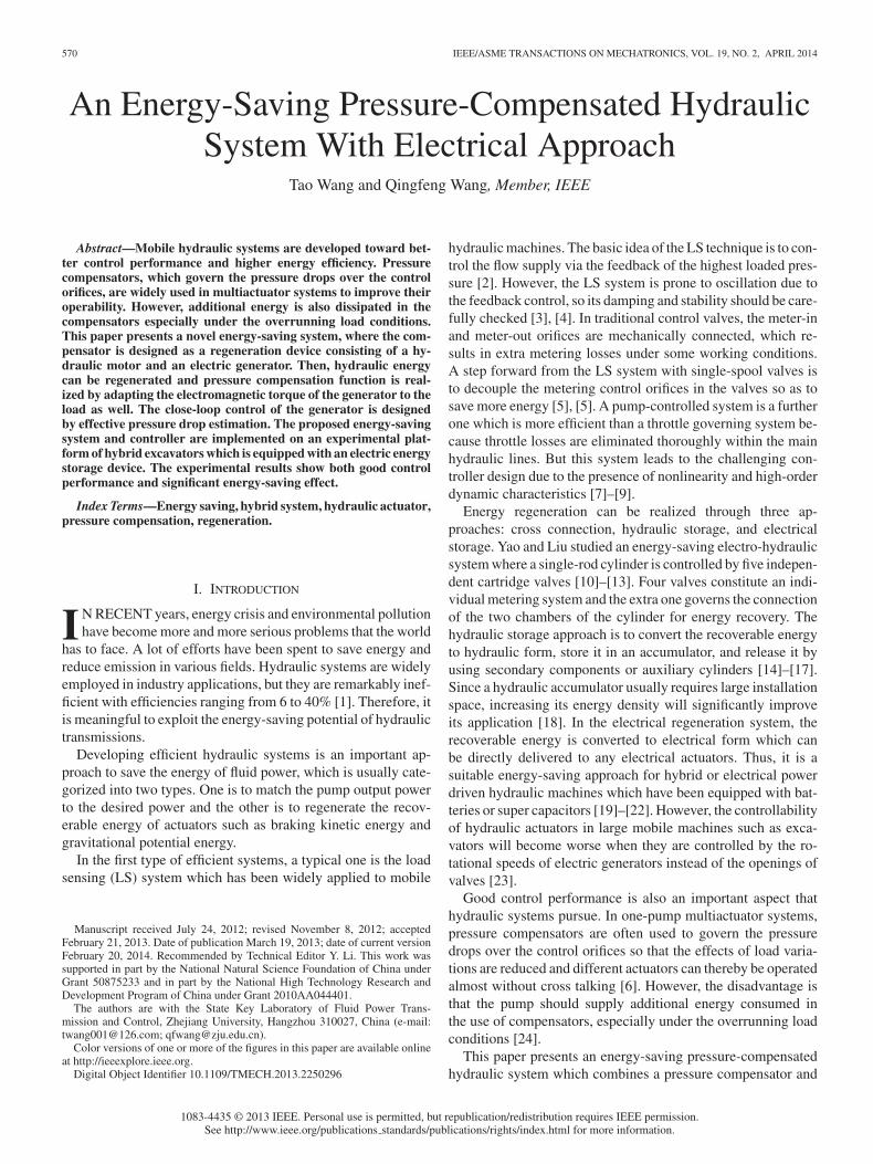
The proposed energy-saving system and controller are im-plemented on an experimental platform of hybrid excavators asshown in Fig. 5.
In the platform, the piston and rod diameters of the cylinderare 0.115 and 0.065 m, respectively. The pump, which is drivenby a hybrid power source consisting of an engine and an elec-tric machine, can maximally supply 0.002 m3 hydraulic oil persecond with 31.5 MPa pressure. The nominal flow rate of theproportional directional flow valve is 1.67e-3 m3 /s. The fixeddisplacement of the hydraulic motor is 5.5e-5 m3 . The pump,valve, and motor are all Bosch Rexroth products. The permanentmagnet synchronous generator, which is specially designed tosatisfy the requirements of the regeneration application, has a
Qv (s)Pi (s)
= Kvp
JtVm
βes2 +
[JtCt + Vm
βe
(λDm
2π Kmω + Bm
)]s +
(λDm
2π Kmω + Bm
)Ct + D 2
m
4π 2
JtVm
βes2 +
[Jt (Kvp + Ct) + Vm
βe
(λDm
2π Kmω + Bm
)]s +
(λDm
2π Kmω + Bm
)(Kvp + Ct) + D 2
m
4π 2
(14)
574 IEEE/ASME TRANSACTIONS ON MECHATRONICS, VOL. 19, NO. 2, APRIL 2014
Fig. 5. Experimental platform schematic diagram for hybrid excavators.
Fig. 6. Partial hardware of the experimental platform.
maximum electromagnetic torque of 160 Nm. The super capac-itor is a Maxwell product of which the capacity and nominalvoltage are 6.25 F and 400 V. The converter is an Infineonproduct of which the maximum current and voltage are 200 Aand 600 V. The real-time control algorithm is implemented ina digital signal processing card dSPACE DS1104. A rotationalposition sensor with 3200 pulses per revolution is used to de-tect the rotor position and speed information of the generatorfor vector control and flow rate calculation. The sampling rateis 10 kHz in the vector control of the generator and 1 kHz
Fig. 7. Velocity step responses without load.
Fig. 8. Velocity step responses with load.
in other situations. The experimental system is also equippedwith auxiliary sensors including flow meters, pressure sensors,displacement sensors, torque sensors, and current and voltagesensors, which are used to monitor the system’s states. Fig. 6shows partial hardware of the platform.
B. Basic Motion Tests
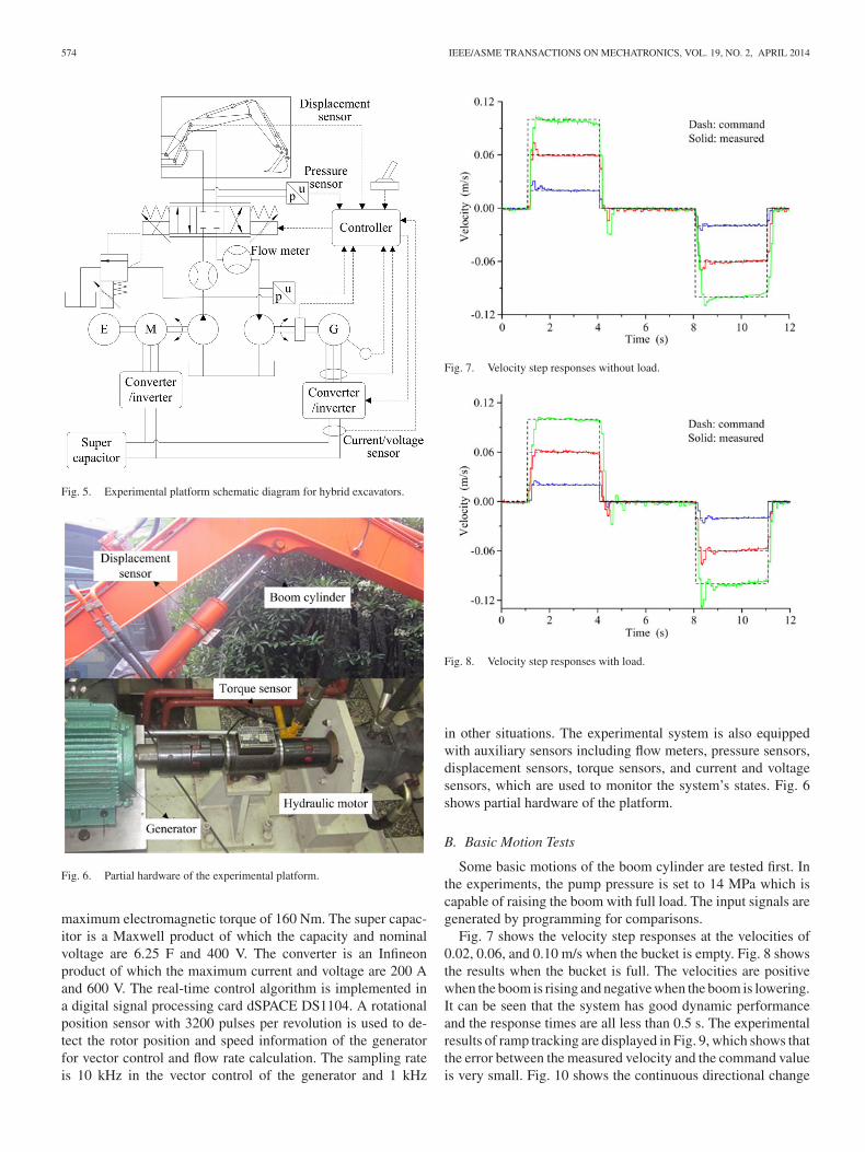
Some basic motions of the boom cylinder are tested first. Inthe experiments, the pump pressure is set to 14 MPa which iscapable of raising the boom with full load. The input signals aregenerated by programming for comparisons.
Fig. 7 shows the velocity step responses at the velocities of0.02, 0.06, and 0.10 m/s when the bucket is empty. Fig. 8 showsthe results when the bucket is full. The velocities are positivewhen the boom is rising and negative when the boom is lowering.It can be seen that the system has good dynamic performanceand the response times are all less than 0.5 s. The experimentalresults of ramp tracking are displayed in Fig. 9, which shows thatthe error between the measured velocity and the command valueis very small. Fig. 10 shows the continuous directional change

WANG AND WANG: AN ENERGY-SAVING PRESSURE-COMPENSATED HYDRAULIC SYSTEM WITH ELECTRICAL APPROACH 575
Fig. 9. Velocity ramp tracking without load.
Fig. 10. Continuous directional change of velocity without load.
of velocity. It can be observed that the practical velocity anddisplacement vary smoothly without oscillation. It also showsthat the overshoot can be reduced by adding a proper ramp to astep input signal.
C. Pressure Compensation Function
Then, experiments are carried out to verify the compensationfunction. Since the boom cylinder is a single rod and asymmet-ric, the predetermined pressure drops over the metering orificeare set to 0.5 MPa when the boom is rising and 2 MPa whenlowering. Fig. 11 shows the experimental results at velocity of0.06 m/s. It can be observed that the actual pressure drops areclose to the desired constants and the generator torque is adaptiveto the load pressure. The regenerated energy is indicated by thecharging currents and voltage variations. As shown in Fig. 11,more energy is regenerated under no-load condition than underloaded condition when the boom is rising. And the conclusion isjust the opposite when the boom is lowering. Therefore, the ex-perimental results are consistent with the analytical expressions(1) and (2) in Section II.
Fig. 12 shows the experimental results under simulated loaddisturbance, which is realized by changing the pump pressure.The pump pressure becomes 17 from 14 MPa at 4 s and backs to14 MPa at 12 s. It can be seen that the pressure drop over the ori-fice is kept constant, although the load condition is changed. Inaddition, the velocity variations due to the sudden disturbancesare less than 10%.
Fig. 13 shows the experimental results in digging operation.In this operation, the bucket hits the ground during loweringprocess. The load condition becomes very large resistive loadand the lowering velocity is near to zero. Thus, there is almostno energy to recover. As shown in Fig. 13, the rod side pressurequickly increases and the piston side pressure decreases as soonas the hit happens at 4 s. The torque control command of thegenerator saturates to zero, for the calculated pressure dropbecomes much smaller than the predetermined value. Therefore,the digging operation can be well performed in the proposedsystem.
D. Energy-Saving Evaluation
To evaluate the energy-saving effect, some definitions aremade as follows:
Es =∫
PsQsdt (15)
Ec =∫
(P1Q1 − P2Q2) dt (16)
Em =∫
Pm Qm dt (17)
Ee =∫
UeIedt (18)
where Es is the pump supplied energy, Qs is the pump flow rate,Ec is the cylinder energy consumption, Em is the recoverableenergy in the inlet chamber of the hydraulic motor, Ee is regen-erated electrical energy in the super capacitor, and Ue and Ie arethe voltage and charging current of the super capacitor. It shouldbe mentioned that the cylinder energy consumption is negativewhen the external input energy is larger than the frictional lossesin the cylinder.
Considering a total rising and lowering cycle, some indexesrelated with efficiency are defined as
ηhyd = Em /Es (19)
ηreg = Ee/Em (20)
ηtot = Ee/Es (21)
where ηhyd denotes the ratio of the recoverable hydraulic energyto the pump supplied energy, ηreg denotes the energy conversionefficiency of the regeneration device, and ηtot denotes the totalregeneration efficiency.
The energy distributions are calculated in the process whenthe boom cylinder rises and lowers for 3 s, respectively, witha velocity of 0.06 m/s. Both of the no-load and loaded condi-tions are researched and the results are shown in Table II. Thetotal quantities of regenerated energy are approximately equal

576 IEEE/ASME TRANSACTIONS ON MECHATRONICS, VOL. 19, NO. 2, APRIL 2014
Fig. 11. Experimental results at velocity of 0.06 m/s. (a) Rising with resistive load. (b) Lowering with overrunning load.
TABLE IIENERGY-SAVING EVALUATION
to each other under the two load conditions. Table III shows thedetailed data of efficiencies. It can be seen that more than 50% of
TABLE IIIREGENERATION EFFICIENCIES
pump-supplied energy is recoverable and more than 30% is re-generated. The energy conversion efficiency of the regenerationdevice is about 60%, which is related to the hydraulic motor,the electric generator, and the super capacitor.

WANG AND WANG: AN ENERGY-SAVING PRESSURE-COMPENSATED HYDRAULIC SYSTEM WITH ELECTRICAL APPROACH 577
Fig. 12. Experimental results with simulated disturbance.
Fig. 13. Experimental results in digging operation.
V. CONCLUSION
In this paper, an electric regeneration device was used totake the place of a traditional hydraulic compensator in or-der to obtain a more efficient hydraulic system. The pressure-compensated function was realized by a simple feedback controlof an estimated pressure drop. The effectiveness of the proposedsystem and controller was validated by substantial experimentalresults under various load conditions and operating modes. Theresults show that both good control performance and significantenergy-saving effect are achieved.
Considering the cost of the electric energy storage device,it is recommended to apply this system to hybrid or electricalpower driven hydraulic machines. Future work will focus onpractical application, and some additional points such as systemreliability, optimized, and integrated design of the regenerationdevice will be studied.
REFERENCES
[1] K. A. Stelson, “Saving the world’s energy with fluid power,” in Proc. 8thJFPS Int. Symp. Fluid Power, Oct. 25–28, 2011, pp. 1–7.
[2] R. Finzel, S. Helduser, and D.-S. Jang, “Electro-hydraulic control systemsfor mobile machinery with low energy consumption,” in Proc. 7th Int.Conf. Fluid Power Transm. Control, 2009, pp. 214–219.
[3] D. Wu, R. Burton, G. Schoenau, and D. Bitner, “Establishing operatingpoints for a linearized model of a load sensing system,” Int. J. Fluid Power,vol. 3, no. 2, pp. 47–54, Aug. 2002.
[4] D. Lovrec, M. Kastrevc, and S. Ulaga, “Electro-hydraulic load sensingwith a speed-controlled hydraulic supply system on forming-machines,”Int. J. Adv. Manuf. Technol., vol. 41, no. 11–12, pp. 1066–1075, Apr. 2009.
[5] Y. Liu, B. Xu, H. Yang, and D. Zeng, “Modeling of separate meter in andseparate meter out control system,” in Proc. IEEE/ASME Int. Conf. Adv.Intell. Mechatronics., Jul. 2009, pp. 227–232.
[6] B. Eriksson and J.-O. Palmberg, “Individual metering fluid power systems:challenges and opportunities,” in Proc. Inst. Mech. Eng., J. Syst. ControlEng., Mar. 2011, vol. 225, no. 2, pp. 196–211.
[7] J. Grabbel and M. Ivantysynova, “An investigation of swash plate controlconcepts for displacement controlled actuators,” Int. J. Fluid Power, vol. 6,no. 2, pp. 19–36, Aug. 2005.
[8] Y. Lin, Y. Shi, and R. Burton, “Modeling and robust discrete-time sliding-mode control design for a fluid power electrohydraulic actuator (EHA)system,” IEEE/ASME Trans. Mechatronics, vol. 18, no. 1, pp. 1–10, Feb.2013.
[9] L. Wang, W. J. Book, and J. D. Huggins, “Application of singular pertur-bation theory to hydraulic pump controlled systems,” IEEE/ASME Trans.Mechatronics, vol. 17, no. 2, pp. 251–259, Apr. 2012.
[10] S. Liu and B. Yao, “Energy-saving control of single-rod hydraulic cylin-ders with programmable valves and improved working mode selection,”paper presented at the Int. Off-Highway Powerplant Congr., Las Vegas,NV, USA, 2002, Paper 2002-01-1343.
[11] S. Liu and B. Yao, “Automated onboard modeling of cartridge valve flowmapping,” IEEE/ASME Trans. Mechatronics, vol. 11, no. 4, pp. 381–388,Aug. 2006.
[12] S. Liu and B. Yao, “Coordinate control of energy saving programmablevalves,” IEEE Trans. Control Syst. Technol., vol. 16, no. 1, pp. 34–45, Jan.2008.
[13] B. Yao, “Integrated mechatronic design of precision and energy savingelectro hydraulic systems,” in Proc. 7th Int. Conf. Fluid Power Transm.Control, 2009, pp. 360–372.
[14] X. G. Liang and T. Virvalo, “An energy recovery system for a hydrauliccrane,” in Proc. Inst. Mech. Eng., J. Mech. Eng. Sci., Jun. 2001, vol. 215,no. 6, pp. 737–744.
[15] T. H. Ho and K. K. Ahn, “Design and control of a closed-loop hydraulicenergy-regenerative system,” Autom. Constr., vol. 22, pp. 444–458, Mar.2012.
[16] T. H. Ho and K. K. Ahn, “Speed control of a hydraulic pressure couplingdrive using an adaptive fuzzy sliding-mode control,” IEEE/ASME Trans.Mechatronics, vol. 17, no. 5, pp. 976–986, Oct. 2012.

578 IEEE/ASME TRANSACTIONS ON MECHATRONICS, VOL. 19, NO. 2, APRIL 2014
[17] H. Yang, W. Sun, and B. Xu, “New investigation in energy regenerationof hydraulic elevators,” IEEE/ASME Trans. Mechatronics, vol. 12, no. 5,pp. 519–526, Oct. 2007.
[18] P. Y. Li, J. D. Van de Ven, and C. Sancken, “Open accumulator conceptfor compact fluid power energy storage,” in Proc. ASME Int. Mech. Eng.Congress R&D Expo., 2007, pp. 127–140.
[19] T. O. Andersen, M. R. Hansen, H. C. Pedersen, and F. Conrad, “Regen-eration of potential energy in hydraulic forklift trucks,” in Proc. 6th Int.Conf. Fluid Power Transm. Control, 2005, pp. 302–306.
[20] T. Minav, P. Immonen, L. Laurila, V. Vtorov, J. Pyrhonen, and M. Niemela,“Electric energy recovery system for a hydraulic forklift - theoretical andexperimental evaluation,” IET Electric Power Appl., vol. 5, no. 4, pp. 377–385, Apr. 2011.
[21] T. Minav, J. Pyrhonen, and L. Laurila, “Permanent magnet synchronousmachine sizing: effect on the energy efficiency of an electrohydraulicforklift,” IEEE Trans. Ind. Electron., vol. 59, no. 6, pp. 2466–2474, Jun.2012.
[22] B.-I. Kang and S. B. Oh, “A study on the boom energy regenerationsystem for a hybrid excavator,” in Proc. 7th Int. Fluid Power Conf., 2010,pp. 129–142.
[23] T. L. Lin, Q. F. Wang, B. Z. Hu, and W. Gong, “Research on the energyregeneration systems for hybrid hydraulic excavators,” Autom. Constr.,vol. 19, no. 8, pp. 1016–1026, Dec. 2010.
[24] P. Marani, G. Aasaloni, and R. Paoluzzic, “Load Sensing with activeregeneration system,” in Proc. 7th JFPS Int. Symp. Fluid Power, 2008,pp. 617–622.
[25] B. Yao, F. Bu, J. Reedy, and G. T.-C. Chiu, “Adaptive robust motion controlof single-rod hydraulic actuators: theory and experiments,” IEEE/ASMETrans. Mechatronics, vol. 5, no. 1, pp. 79–91, Mar. 2000.
Tao Wang received the B.Eng. degree from ZhejiangUniversity, Hangzhou, China, in 2008, where he iscurrently working toward the Ph.D. degree in mecha-tronic control engineering.
His research interests include permanent-magnetmachines and energy recovery.
Qingfeng Wang (M’11) received the M.Eng. andPh.D. degrees in mechanical engineering from Zhe-jiang University, Hangzhou, China, in 1988 and 1994,respectively.
In 1994, he became a faculty member with Zhe-jiang University, where he was promoted to the rankof Professor in 1999. He was the Director of the StateKey Laboratory of Fluid Power Transmission andControl at Zhejiang University from 2001 to 2005and currently serves as the Director of the Institute ofMechatronic Control Engineering. His research inter-
ests include electro-hydraulic control components and systems, hybrid powersystems and energy saving techniques for construction machinery, and systemsynthesis for mechatronic equipment.