Embed Size (px)
Citation preview

An endoscopic capsule robot: a meso-scale engineering case study
This article has been downloaded from IOPscience. Please scroll down to see the full text article.
2009 J. Micromech. Microeng. 19 105007
(http://iopscience.iop.org/0960-1317/19/10/105007)
Download details:
IP Address: 193.205.81.1
The article was downloaded on 20/09/2009 at 16:58
Please note that terms and conditions apply.
The Table of Contents and more related content is available
HOME | SEARCH | PACS & MSC | JOURNALS | ABOUT | CONTACT US

IOP PUBLISHING JOURNAL OF MICROMECHANICS AND MICROENGINEERING
J. Micromech. Microeng. 19 (2009) 105007 (11pp) doi:10.1088/0960-1317/19/10/105007
An endoscopic capsule robot: ameso-scale engineering case study
Claudio Quaglia1, Elisa Buselli1, Robert J Webster III2, Pietro Valdastri1,Arianna Menciassi1,3 and Paolo Dario1,3
1 Scuola Superiore Sant’Anna—CRIM Lab, Viale R Piaggio 34, Pisa, Italy2 Department of Mechanical Engineering, Vanderbilt University, 2301 Vanderbilt Place, Nashville,TN, USA3 Italian Institute of Technology Network, Genova, Italy
E-mail: [email protected]
Received 10 August 2009Published 16 September 2009Online at stacks.iop.org/JMM/19/105007
Abstract
A number of unique challenges arise in fabricating and assembling complex mechanisms atthe meso-scale (hundreds of microns to centimetres). In general, for a complex multi-partmechanism at this length scale, no single machining technique can produce all the necessaryparts—or often even a single individual part. Towards developing a comprehensive set of ‘bestpractices’ for combining multiple precision micromachining operations at the meso-scale, wepresent a case study on fabricating and assembling an endoscopic capsule robot. Existingpassive imaging capsules have proven exceptionally useful in the diagnosis of thegastrointestinal tract, and robotic capsules promise to enhance their diagnostic capabilities andenable non-invasive treatment delivery. In this case study, we describe the fabrication of arobotic capsule (2.6 cm3 in volume) containing a complex mechanism consisting of 72components, each of which requires a variety of meso- or even micro-scale features. Wedescribe the manufacturing processes used to produce these components and features(combinations of high precision, multiply refixtured computer numerical control processes,sink and wire electro discharge machining , laser cutting, etc). These results contribute to theemerging framework of best practices in meso-scale design and manufacture, illustrating waysto effectively combine several processes to produce a complex meso-scale device.
(Some figures in this article are in colour only in the electronic version)
1. Introduction
The meso-scale can be defined as the dimensions thatlie between the traditional macro and micro-scales, fromhundreds of microns to centimetres [1, 2]. This length scalepresents a number of unique design and fabrication challenges.Components often must be fabricated in a multi-step processrequiring refixturing between steps and/or combinations ofseveral different manufacturing technologies to create asingle part. Assemblies made from such components mustbe carefully designed with appropriate tolerances betweentheir reference surfaces. Strategies must also be developedfor maintaining manufacturing accuracy when refixturing ormoving parts between machines. Developing a generalframework of best practices for such meso-scale design,fabrication and assembly tasks can be facilitated by case
studies such as the endoscopic capsule robot that we discuss inthis paper. Such case studies serve to elucidate the challengesand possible solutions involved in creating complex assembliesat the meso-scale.
In this paper, we present the design, fabrication andassembly of a novel wireless endoscopic capsule robotintended for medical applications (see figures 1–3). Capsulerobots must be small enough to swallow and require complexminiature mechanisms in order to control their position andorientation. The prototype we discuss in this paper matchesthe dimensions of commercial, Food and Drug Administration(FDA) approved ‘camera pills’ [3] almost exactly. It isa cylinder 11.1 mm in diameter and 27 mm long and itcontains 72 components. Fabricating these componentsrequired the combination of a number of manufacturingtechniques including computer numerical control (CNC),
0960-1317/09/105007+11$30.00 1 © 2009 IOP Publishing Ltd Printed in the UK

J. Micromech. Microeng. 19 (2009) 105007 C Quaglia et al
Figure 1. The assembled endoscopic capsule robot that is the focusof our case study. Its internal components are shown in figure 3.
Figure 2. CAD drawing of the assembled internal components ofthe capsule robot. Component dimensions range from 23.6 mm(length of the capsule body) to 0.4 mm (diameter of the pins).
Figure 3. Fabricated internal mechanical components of the capsulerobot before assembly. The assembly procedure is discussed insection 5, and the assembled prototype is shown in figure 1.
sink and wire electro discharge machining (EDM) and lasercutting.
The paper is organized as follows: section 2 presentsrelated work in meso-scale design and fabrication, as well asthe background and medical motivation for capsule robots.In section 3, we discuss individual components themselves,material choices and fabrication procedures. Then, in section 4we present experimental assessment of fabrication accuracy ofindividual components. In section 5, we discuss the assembly
procedure for the capsule robot. Section 6 summarizes anddiscusses results, highlighting the lessons learned from thiscase study for future meso-scale design and manufacturingtasks.
2. Background and related work
2.1. Background on meso-scale fabrication
Meso-scale components with complex features areincreasingly required in aerospace, electronics, biomedicineand communications, among other applications. A survey ofcurrently available techniques for the meso-scale reveals twomain approaches: scaling up technologies typically appliedin microelectromechanical systems (MEMS) or scaling downmacro-scale techniques using ultra-precision machining [4].MEMS techniques are generally used for micro-fabricationand are limited to thick 2D structures and a narrow class of(mainly silicon-based and thus fragile) materials [5].
Ultra-precision machines can overcome these problems,since they can machine 3D geometry using many types ofmaterials. However, they do not allow batch fabrication, thusrequiring considerable time to reproduce large numbers ofsmall features or to make multiple copies of a given part.Some recent innovative approaches, such as shape depositionmanufacturing (SDM), may eventually overcome this. Whilestill in early stages of development, SDM has the potential tocreate moulds with complex shapes for forming multi-materialmeso-scale devices [6, 7].
Another challenge associated with scaling down large-scale machining techniques is obtaining sufficiently highaccuracy for miniaturized components. This is notstraightforward, due to the lack of small and precise tools andthe inertia of the machine tool, which can lead to substantialerrors at the meso-scale. Other effects that may be neglectedat the macro-scale can also become critical at the meso-scale(e.g. lattice microstructure and surface effects). In orderto overcome the limitations of current technologies, manyresearchers are developing new machines and tools specificallydesigned for meso-scale products [8–10], aiming towardsthe design of microfactories integrating these machines [11],eventually assisted by robotic technologies [12]. A surveyof the current efforts in mechanical micro-machining researchand applications is available in [13].
Until such technologies achieve their promise and reachmaturity, the best available options for precise fabrication atthe meso-scale are the use of advanced, but still in principletraditional, ultra-precision machines. Thus, in this work, wepresent a centimetre-scale robot with most components in themeso-scale domain and several features in the micro-scale,completely developed by ultra-precision machines. A reviewof the state of the art in ultra-precision machining is availablein [14]. A discussion on the limits of EDM technology anda description of a new method to machine complex micro-cavities are available in [15]. It is also possible to use thisapproach in tandem with the computer-aided design (CAD)software to produce small features with exceedingly highprecision [16], by compensating for electrode wear during
2

J. Micromech. Microeng. 19 (2009) 105007 C Quaglia et al
the machining process. Our interest in the present paper isnot to probe the fundamental limits of such manufacturingtechnologies, but rather to investigate means of combiningultra-precision machining techniques to produce a complexmeso-scale mechanism.
2.2. Medical motivation for capsule robots
Encapsulating a camera within a pill is a recent innovationin medical technology [17] which enables non-invasivevisual diagnosis deep within the intestine. The imagesreturned by these wireless capsule endoscopes (WCEs) areextremely valuable medically. They can reveal the locationand severity of lesions or bleeding, enable inspection ofpotentially cancerous growths in the intestinal wall, permitvisual assessment of the overall health of the gastrointestinal(GI) tract, etc. An expanded discussion of the clinical valueof WCEs can be found in [18].
Despite these revolutionary capabilities, current WCEsare unable to directly control their position and orientationwithin the GI tract and must rely on peristalsis—musclecontractions that ordinarily move food during digestion—topropel themselves. This means that they cannot adjust theirspeed, stop or reverse direction, which limits both the quantityand quality of images returned from the site of interest. Suchlimitations are particularly problematic in the large intestinewhere WCEs tumble unpredictably due to the large differencebetween capsule diameter and intestine diameter.
A possible solution consists in a miniature propulsionsystem integrated within the WCE [19]. In particular, anapproach that is particularly well suited to the challengingenvironment of the GI tract is of legged locomotion [20]. Inprior work, the authors have presented a series of increasinglyadvanced prototype capsules for robotic legged locomotion[21, 22].
The most advanced of these legged capsule robots to dateis the 12-leg prototype, for which the design methodology,medical considerations and control strategies can be found in[23]. In following sections, we describe the fabrication of thisrobot as a case study on meso-scale component design andfabrication.
2.3. Capsule robot case-study overview
The capsule robot shown in figure 1 contains twomotors (Namiki Precision Jewel Co. Ltd), each of whichindependently controls a set of six legs. As shown in figure 2,each motor is coupled to a lead screw through a geartransmission. As the lead screw rotates, a nut connectedby pins to leg holders translates axially with respect to thecapsule. The leg holders are also connected via a slotted pinconnection to the capsule exterior wall. Thus, the leg set opensand closes in an ‘umbrella-like’ manner as the nut translates.As can be seen in figures 2 and 3, there are a large numberof meso- and even micro-scale features on the componentsin this mechanism, and thus its fabrication is an illuminatingcase-study in meso-scale engineering.
Figure 4. The two faces of one of the caps. The two cylindricalprotrusions, that are the reference surfaces, are 3.85 mm in diameterand the inter-axis spacing is 6.8 mm.
3. Fabricating capsule robot components
In this section, we describe the manufacturing proceduresfor the components shown in figure 3. We begin with thecapsule cap and body that provide the outer casing for thecapsule and then proceed inward along the kinematic chainfrom the leg to the leg holder to the lead screw to the gearsthat couple lead screws to motor shafts. In addition to a briefdescription of each component, we describe each fabricationstrategy employed and the rationale behind it. Most of the72 components were fabricated using one or more of thesemachines:
(1) Lathe (17D, EMCOMAT, Germany);(2) CNC 5 axis milling machine (HSPC, KERN, Germany);(3) Sink EDM (T1-T4 SR-HPM, Sarix, Switzerland);(4) Wire EDM (AP 200 L, Sodick, Japan);(5) Laser machining: (Nd-YAG laser, Trumpf, Germany).
3.1. The cap
3.1.1. Description. There are four caps, two for eachend of the capsule. Each has a diameter of 11.1 mm andwas machined to house bushings, gears and electronics (seefigure 4). The caps also contain two reference surfaces each,to allow repeatable connection between caps and the capsulebody. These features are highlighted in figure 4.
The caps and body were machined in Ergal 7075 usingthe HSPC KERN milling machine. Ergal has a unique blendof machinability, wear resistance and lightness that make it apopular material choice in airplane manufacture.
3.1.2. Fabrication strategy. The cap was machined startingfrom a rod workpiece. It was fixtured on the HSPC KERNchuck and both the internal and external surfaces and all theholes and reference surfaces were machined on one side. Theworkpiece was then cut to the proper length using a lathe.It was then inverted and refixtured on the HSPC KERN formachining of the opposite side (see figure 4 for the twofinished faces, and figure 5 for refixturing images). In orderto perform this step maintaining correct reference to the sidewhich was already shaped, a custom cap fixture was fabricateddirectly on the HSPC KERN. It was built using a cylindrical
3

J. Micromech. Microeng. 19 (2009) 105007 C Quaglia et al
Figure 5. The custom cap fixture used for refixturing the caps onthe machine. The holes shown are 3.95 mm in diameter. The rightimage shows the fixture with a cap in place on it, just aftermachining the cap’s second face.
workpiece, into which was machined a negative cap profile(figure 5). After machining, this cap fixture was left in placeon the HSPC KERN, to remove chuck jaw refixturing as asource of error. The cap was then bonded to the cap fixtureusing cyanoacrylate glue and the second face of the cap wasmachined. To disassemble the cap from the cap fixture afterremoval from the HSPC KERN, both the parts were dippedinto an acetone solvent to release the glue.
The critical dimensions of the cap fixture were the twoholes that guarantee a precise assembly with the cap. Thedistances between the hole centres in the fixture were designedto be slightly bigger than in the cap, in order to obtain an easyand accurate placement. Therefore, we chose a tolerance of−0.03 mm for this parameter. Given this assumption, theinterference with the cap should not exceed 0.06 mm. Seesection 4.1 for further details on these dimensions.
An additional challenge in cap fabrication was machiningthe several thin regions (approximately 150 μm) theycontained. Through a trial and error procedure performed withthe HSPC KERN, it was determined that these thin regionscould be fabricated without significant material deformationprovided that the tool feed was reduced approximately 30%from the tool supplier recommendations for Ergal.
3.2. The body
3.2.1. Description. The capsule body has a diameter of11.1 mm and a length of 23.6 mm and houses all internalcomponents. Twelve 14.1 mm slits for the legs are cut into itsexternal surface, along with 0.4 mm diameter holes for eachof the pins that support the leg holders at the capsule wall (seefigure 6).
3.2.2. Fabrication strategy. Creating the internal features ofthe capsule body (figures 7 and 8) required two processes—one from each end of the cylinder—for two reasons. First,small internal features require use of a small-diameter endmill, which must have a correspondingly short cuttinglength to prevent tool chatter. Second, the internal geometrydoes not go all the way through the capsule—a ‘plate’ of
Figure 6. The capsule body is 11.1 mm in diameter, 23.6 mm longand its smallest features are 12 holes of 0.4 mm diameter.
Figure 7. The fabricated capsule body, made from Ergal.
Figure 8. An axial view of the capsule, showing assembled motors(right and left circular parts) and the central nut.
material 1.5 mm thick is left in the middle of the capsule bodyto support the bushings which hold the ends of the lead screws.
Thus, the capsule body began as a solid cylindrical Ergalworkpiece 11.1 mm in diameter, which was machined on oneend (side A shown in figure 7) using the HSPC KERN to createthe profile shown in figure 8. Then the workpiece was cut tolength using a lathe in preparation for machining side B. In
4
J. Micromech. Microeng. 19 (2009) 105007 C Quaglia et al
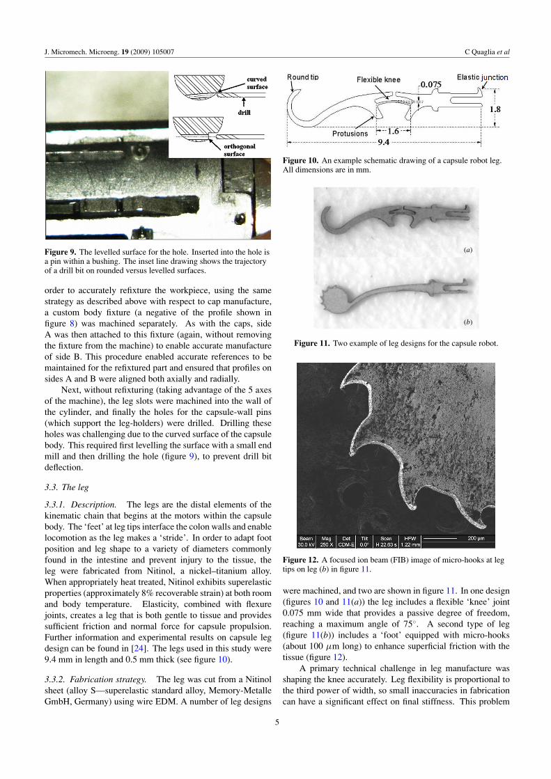
Figure 9. The levelled surface for the hole. Inserted into the hole isa pin within a bushing. The inset line drawing shows the trajectoryof a drill bit on rounded versus levelled surfaces.
order to accurately refixture the workpiece, using the samestrategy as described above with respect to cap manufacture,a custom body fixture (a negative of the profile shown infigure 8) was machined separately. As with the caps, sideA was then attached to this fixture (again, without removingthe fixture from the machine) to enable accurate manufactureof side B. This procedure enabled accurate references to bemaintained for the refixtured part and ensured that profiles onsides A and B were aligned both axially and radially.
Next, without refixturing (taking advantage of the 5 axesof the machine), the leg slots were machined into the wall ofthe cylinder, and finally the holes for the capsule-wall pins(which support the leg-holders) were drilled. Drilling theseholes was challenging due to the curved surface of the capsulebody. This required first levelling the surface with a small endmill and then drilling the hole (figure 9), to prevent drill bitdeflection.
3.3. The leg
3.3.1. Description. The legs are the distal elements of thekinematic chain that begins at the motors within the capsulebody. The ‘feet’ at leg tips interface the colon walls and enablelocomotion as the leg makes a ‘stride’. In order to adapt footposition and leg shape to a variety of diameters commonlyfound in the intestine and prevent injury to the tissue, theleg were fabricated from Nitinol, a nickel–titanium alloy.When appropriately heat treated, Nitinol exhibits superelasticproperties (approximately 8% recoverable strain) at both roomand body temperature. Elasticity, combined with flexurejoints, creates a leg that is both gentle to tissue and providessufficient friction and normal force for capsule propulsion.Further information and experimental results on capsule legdesign can be found in [24]. The legs used in this study were9.4 mm in length and 0.5 mm thick (see figure 10).
3.3.2. Fabrication strategy. The leg was cut from a Nitinolsheet (alloy S—superelastic standard alloy, Memory-MetalleGmbH, Germany) using wire EDM. A number of leg designs
Figure 10. An example schematic drawing of a capsule robot leg.All dimensions are in mm.
(a)
(b)
Figure 11. Two example of leg designs for the capsule robot.
Figure 12. A focused ion beam (FIB) image of micro-hooks at legtips on leg (b) in figure 11.
were machined, and two are shown in figure 11. In one design(figures 10 and 11(a)) the leg includes a flexible ‘knee’ joint0.075 mm wide that provides a passive degree of freedom,reaching a maximum angle of 75◦. A second type of leg(figure 11(b)) includes a ‘foot’ equipped with micro-hooks(about 100 μm long) to enhance superficial friction with thetissue (figure 12).
A primary technical challenge in leg manufacture wasshaping the knee accurately. Leg flexibility is proportional tothe third power of width, so small inaccuracies in fabricationcan have a significant effect on final stiffness. This problem
5

J. Micromech. Microeng. 19 (2009) 105007 C Quaglia et al
Figure 13. A longitudinal section of the leg holder. Its total lengthis 7.38 mm, while its minimum feature, the pin guide, is 0.4 mmwide. The inset shows the leg seats.
was addressed by using an initial rough cut, followed by severalfinishing passes to cut the knee to the desired dimensions.
Laser cutting was also investigated as an alternativefabrication technique, given its higher speed if compared towire EDM. Thus legs in the shapes represented in figures 10and 11(a) were also cut using the laser cutter mentionedpreviously.
3.4. The leg holder
3.4.1. Description. Working inward along the kinematicchain, each leg snaps into a leg-holder (figure 13), whichinterfaces with a pin at the capsule wall and a pin on thenut threaded onto the lead screw (see figure 2). The legholder was fabricated from steel (all components in the capsulethat are subject to high mechanical stresses or friction weremachined in steel to reduce wear and prolong the life of thecapsule).
3.4.2. Fabrication strategy. The external profile of the legholder was machined using wire EDM and the pockets intowhich the legs snap (the ‘leg seats’) were fabricated usingsink EDM. For this purpose, an electrode that was a negativeof the leg seat was fabricated both using the HSPC KERN(rough shaping to enable fixturing of the part in the sink EDMmachine) and wire EDM (for cutting the electrode profile).The resulting negative electrodes are shown in figure 14.The negative electrode has the dimensions of the leg seatpocket: a rectangular profile 0.9 mm wide and 0.5 mm thick.Unfortunately, the electrical arcs used in plunge etching dogradually wear away the electrode material. For this reason,we fabricated several electrode negatives for the leg seats,as shown in figure 14. In particular, three electrodes wererequired to machine each leg holder.
The pin guide (see figure 13) was machined by wire EDMstarting from a smaller diameter hole made with a standarddrill. In order to achieve high surface quality with the wireEDM, we refined the shape through several finishing passesafter an initial rough cut.
3.5. The lead screw
3.5.1. Description. Two steel lead screws were used to drivethe nuts that impart force to the leg holders. On one end
Figure 14. A photo taken after using the electrode negatives tocreate the leg seat pockets in the leg holders. This photo shows fourelectrodes 0.9 mm wide by 0.5 mm thick after a single use.
Figure 15. Drawing of the lead screw tip that interfaces with thegear. φ = 0.45 mm and l = 0.28 mm.
a smooth cylindrical profile was created to interface with abushing at the centre of the capsule. On the other end, theprofile shown in figure 15 was created to enable it to interfacewith the larger central gear that can be seen in figure 2.
3.5.2. Fabrication strategy. The lead screw began as acommercial threaded rod (ISO M1 with a triangular profile).The primary considerations in choosing this profile were sizeand cost—it is useful to choose a small standard screw sizeso that a commercial tap can be used to thread the nuts. Thethreads were removed on short sections near the end of the leadscrew. Thus, the primary fabrication challenge was shaping theend geometry shown in figure 15. This geometry is composedof two profiles, namely a φ = 0.45 mm cylindrical regionand a flattened tab 0.28 mm thick, which is inserted into thegear. A relatively large clearance (0.05 mm) is used at thescrew–gear interface, making the assembly less sensitive tosmall positioning errors between the body and the caps.
We first attempted to fabricate the profile shown infigure 15 using the HSPC KERN. However, this method causedplastic deformation of the screw tip, so we opted for wire EDM.
3.6. The gears
3.6.1. Description. A gear transmission is included betweenthe lead screw and motor to transmit and amplify torque fromthe motor to the lead screw. Gears with 17 and 40 teethwere fabricated to create this transmission. The smaller gearwas attached to the motor shaft through the hole shown in
6

J. Micromech. Microeng. 19 (2009) 105007 C Quaglia et al
Figure 16. The brass gear. The design value for the addendumradius is 1.140 mm.
figure 16. Since the fabrication method for both sizes ofgear was the same, we discuss only the smaller gear in detailbelow.
3.6.2. Fabrication strategy. The traditional approach totoothed gear fabrication takes advantage of dedicated tools,based on standard modules. However, due to the stringentsize requirements associated with fitting the entire mechanismin the available space inside the capsule, we required gearswith modules smaller than those commercially available. Onepossible solution to this is to construct a customized toolfor gear fabrication. However, this would have substantiallyincreased the time and cost of the fabrication process.
Thus, we chose to use wire EDM to directly fabricate thegears. We believe that this approach is most useful for smallquantities of custom module gears. When large quantitiesof identical gears are required, we suggest fabrication of adedicated gear cutting tool for use on a gear cutting machineto achieve the desired module.
A brass plate was first machined using the HSPC KERNto create a round central hole. This hole was then enlargedand shaped as shown in figure 16 using the wire EDM. Thisparticular quasi-rectangular shape was required to insert themotor shaft into the hole. We chose a custom module of0.12 mm, which is a trade-off between the gear dimensionconstraints and ease of fabrication.
The wire EDM machine requires as input the Cartesiancoordinates of sufficiently closely spaced points on the gearprofile. We began with the characteristic parameters of thetoothed gears (the module m and the number of teeth z).Then, applying standard gear theory [25], we developeda spreadsheet-driven software program that generated thecoordinates of the profile points (figure 17). Finally, thesedata were exported in a file that was compatible with themachine.
As regards tolerance, a maximum deviation of −5 μmfrom the gear parameters’ nominal values was adopted inorder to obtain a correct assembly among the gear and theother components of the mechanism. This tolerance wouldallow for an acceptable clearance, thus guaranteeing properoperation of the device.
Figure 17. Shown above are curves taken from the output of thespreadsheet software that were used to define the gear tooth shape:(1) tooth profile, (2) evolvent curve; (3) profile of the curve easing;(4) addendum circle; (5) pitch circle; (6) base circle; (7) root circle.
Figure 18. Measurement data from the VideoCheck machine. Thecap (left) and the cap fixture (right).
4. Characterization and measurements
After manufacturing each of the components of the capsulerobot as described in section 3 above, we conducted a seriesof measurements to evaluate the errors on specific featuresthat are important to the overall function of the capsule robot.In particular, we used a digital optical microscope (MX-5040RZ, Hirox, USA) and a Multisensor coordinate measurementmachine (Benchtop VideoCheck R© EA 400, Werth, Germany).In this section, we describe the results of these validationexperiments.
4.1. The cap
Using the VideoCheck, we measured both the cap and the capfixture described in section 3.1 (figure 18).
The measured value of interference is
In =(
C − A + B
2
)−
(F − D + E
2
)= −0.0039 mm.
This interference enabled an accurate axial positioning andrigid fixturing (when combined with glue, as described insection 3.1) of the cap on the fixture.
7

J. Micromech. Microeng. 19 (2009) 105007 C Quaglia et al
Figure 19. Two leg flexure joints machined with differenttechniques: (left) wire EDM; (right) laser cutting.
Figure 20. Cross-sections of knee flexure joints manufactured,using (left) wire EDM, and (right) laser cutting.
4.2. The leg
We measured the knee associated with the leg design shownin figure 10, because it is the most critical part regardingmanufacture. In particular, we compared the quality of wireEDM and laser cutting techniques. A first evaluation wasmade by optical microscope as shown in figure 19.
The two legs were then imaged using a focused ion beam(FIB) microscope (200 THP, FEI, USA) and figure 20 showscross sections of the knee. The leg cut by wire EDM has arectangular cross-section as planned, while the cross-sectionof the laser cut knee is triangular. The knee can be modelled asa beam subject to bending; thus, according to elementary beamtheory, the relationship between the applied bending momentM and the curvature κ of the beam is
κ = M
EI, (1)
where E is the elastic modulus of the material and I is the cross-sectional inertia of the beam. Thus, all material propertiesand moments being equal, a beam with a triangular profileof a given height will have 1/3 the flexural rigidity (EI )of a rectangular beam of the same height (see figure 20).This reduction in rigidity is not acceptable for the devisedapplication.
4.3. The leg holder
We measured the length and the width of the pin guide, thediameter of the pin hole where the leg holder connects to the
Figure 21. Measurement results of the leg holder.
Table 1. Measurement results for the leg holder.
Design Average Minimum Maximum Standardvalue value value value deviation(mm) (mm) (mm) (mm) (mm)
A 0.4 0.406 0.403 0.408 0.0015B 1.7 1.717 1.641 1.809 0.058C 0.5 0.504 0.501 0.507 0.002D 0.9 0.921 0.911 0.934 0.008E 0.5 0.523 0.511 0.538 0.009
nut and the dimensions of the leg seat. These measurementswere repeated for six leg holders. In figure 21, one example ofthe measurements is shown and all the results are summarizedin table 1.
The hole for the pin (C) and the width of the guide (A)were machined with a good precision and repeatability. Thevariability in the length of the guide does not affect either theassembly or the functioning of the robot; in fact, the guide waspurposely cut long enough that the pin never reaches eitherend of the slot. The measured values for the leg seat presentsome errors, but this is not a problem thanks to the elasticityof the leg junction.
4.4. The lead screw
The machined tip of the lead screw, where it connects with thegear (see figure 15), was observed by the optical microscopeand the value of φ was calculated to be 0.452 mm, comparedwith a design value of 0.450 mm. It has to fit a bushingof 0.455 mm in diameter. With regard to l, we measured0.270 mm, compared with a planned value of 0.280 mm, inorder to fit a 0.29 mm hole in the big toothed gear.
The clearance between the flattened tab and the gear is animportant part of the design because it allows easy assemblyof the components and reduces the risk of damaging the screw.
An example optical microscope image of the lead screwtip is shown in figure 22.
4.5. The gears
To verify the manufacture quality for the small gear,dimensional control was carried out with the VideoChecksystem mentioned earlier. From the measurement system,we obtained the coordinates of points along the gear profile(figure 23). These data were used to calculate the actual gearparameters, which were compared with the design parametersfor the gear (table 2).
8

J. Micromech. Microeng. 19 (2009) 105007 C Quaglia et al
Figure 22. Optical microscope image of the lead screw tip.
Figure 23. Picture of the tooth profile taken by the VideoCheckmachine.
Table 2. Data for the toothed gear. Half-pitch of openings and teeth.Statistical data are obtained considering all the teeth of the gear
Design Average Max. Min.(mm) (mm) (mm) (mm) SD
Opening 0.1884 0.20 0.23 0.19 0.02Teeth 0.1884 0.17 0.20 0.16 0.01
First we note that the gear profile is not perfectly centredwith the gear rotation axis. This is probably due to switchingthe part from the HSPC KERN to the wire EDM. Second,the teeth are slightly smaller than their intended dimensions.This was related to the wire EDM fabrication and could becompensated for by adjusting the profile by the wire and arcdimensions. However, for our purposes it is preferable forgears to be slightly undersized rather than slightly oversized,since undersized gears can mesh with one another. We alsonote that these gears functioned well in our prototype at thedimensions given in table 2.
5. Assembly process
Assembling all the small parts in a meso-scale robot isa challenging operation requiring close attention to avoiddamaging components during assembly. Figure 24 presentsan exploded view of the capsule, illustrating how the parts fittogether.
The general procedure for assembling the capsule is asfollows. Starting with the capsule body, the motors wereinserted and held in place with glue. Next, the bushings wereinserted. Then the subassembly of the nut and leg holders
Figure 24. Exploded view of the capsule robot.
was separately assembled and inserted into each end of thecapsule. In the next step, the two lead screws were insertedin each nut. The caps and gears were then assembled on eachend, followed by snapping one leg into each leg holder usingthe flexure attachment visible in figure 10 at the base of theleg.
One assembly challenge was the insertion of the nut andleg holders into the capsule body, due to the narrow spacebetween the components. Another was in attaching the gearto the screw: care was necessary to prevent breaking the verythin screw tip. An additional challenge was inserting the motorinto the body before the glue dried, fixing it in place.
These challenges led to some broken components duringinitial assembly. Furthermore, care was necessary to keep themechanism clean and free of dirt and chips from the fabricationprocess. With respect to parts fixed by glue, the main challengewas to apply the correct amount of glue. Excessive gluewould spread to unintended locations, while an insufficientamount of glue would dry too rapidly to allow components toseat properly. Fortunately, it was possible to remove the gluewith a solvent, enabling the correct amount to be determinedvia trial and error. None of these assembly challenges wasinsurmountable—the assembled capsule functioned very wellin comparison to overall design objectives regarding footforces and ranges of motion—see [26] for details on theseissues.
6. Discussion and conclusion
The fabrication of a centimetre-size robot, with mostcomponents in the meso-scale domain, was presented inthis paper as a case study on the use of multiple precisionmachining technologies and refixturing processes to createmeso-scale components that can be assembled into complexmechanisms. Many of the components created have complex3D shapes and also present features in the micro-scale.
The single parts and their dimensional features aresummarized in table 3, together with the manufacturingtechniques used to fabricate them, the advantages/disadvantages of the selected solutions and the averagedimensional errors of the finished components. From thetable one can observe that the most complex parts requiredthe synergetic use of several different precision machiningtechniques. One of the main challenges in this case is
9

J. Micromech. Microeng. 19 (2009) 105007 C Quaglia et al
Table 3. Single parts and their dimensional features, manufacturing techniques adopted, advantages/disadvantages of the selected solutionand average dimensional errors of the finished components.
Capsule part Dimensional featuresManufacturingtechniques Advantages/disadvantages Fabrication errors
Cap � = 11.1 mm; smallest features:several 150 μm thick regions
Two HSCP KERNprocesses, one perside
−Particular care was required forpart refixturing
28 μm error in 6.8 mminter-axis spacing
Body � = 11.1 mm; l = 23.6 mm;smallest features: 12 holes of0.4 mm diameter around theexternal surface
Two HSCP KERNprocesses, one perside
−Particular care was required forpart refixturing;−Drilling lateral holes on theexternal surface required asurface levelling procedure.
N/A—no features in thebody requiredexceptionally hightolerances for overalldevice function
Leg l = 9.4 mm; smallest features:0.075 mm thick flexible knee.0.1 mm hooks
Wire EDM + Rectangular profile;−Rougher surface than laser
N/A—legs functionedaccording to designobjectives
Leg l = 9.4 mm; smallest features:0.075 mm wide flexible knee
Laser cutting + Faster than Wire EDM;−Triangular profile
Material erosion impairedcorrect knee shaping
Leg holder l = 7.38 mm; smallest features:0.4 mm wide pin guide
Wire EDM, SinkEDM;The Sink EDMelectrode requiredHSPC KERN andWire EDM
−3 Sink EDM electrodes arerequired to machine 1 leg-holder
8 μm error in 0.4 mm pinguide width; 7 μm errorfor the 0.5 mm hole
Lead screw Relevant features: φ =0.45 mm; l = 0.28 mm
Wire EDM + Plastic deformation wasavoided thanks to the selectedfabrication process
2 μm on φ; 10 μm on l
Gears Addendum radius = 1.140 mm;module = 0.12 mm
HSPC KERN andWire EDM
+ This procedure enabledcompletely customizable gearmodules;−A purposely developedspreadsheet was required to inputthe Cartesian coordinates to theWire EDM
41 μm error for the0.1884 mm half pitch
(a) (b)
Figure 25. The capsule moving in a porcine colon. (a) Externalview in a phantom model and (b) endoscopic view.
maintaining accurate references when moving a part betweenmachines or refixturing it on a given machine.
After fabrication, several measurement techniques wereused to characterize individual parts and compare them to theoriginal design intent. The final test in whether manufacturingaccuracy was sufficient was assembly of the capsule andverification of its function. We were able to successfullyassemble the 72 parts into a working capsule robot thatsuccessfully utilized legged locomotion to travel through theporcine colon (see [26, 27] as well as figure 25).
In initial tests the capsule achieved a maximum speedof 50 mm min−1, which is suitable for performing an entire
colonoscopy in a length of time consistent with conventionalcolonoscopy. The capsule prototype is also able to climb inany direction—including vertically against gravity.
The results presented in this paper on capsule componentmanufacture and assembly illustrate the unique challengesintrinsic to the meso-scale. Perhaps more importantly,they also provide examples of solutions to meso-scalemanufacturing challenges. We believe that the combination ofthese results with those of other researchers will strengthen theemerging framework of best practices in meso-scale design,manufacture and assembly. This will lay the foundation formany innovative future devices.
Acknowledgments
This material is based in part upon work supported by theIntelligent Microsystem Center, KIST, South Korea, in partby the European Commission in the framework of VECTORFP6 European Project EU/IST-2006-033970, as well as theNational Science Foundation GRFP.
The authors would like to thank Novineon HealthcareTechnology Partners GmbH, in Tubingen (Germany), forassistance during the testing phase of the device. The magneticencoder was developed by Sensitec GmbH and laser cuttingof the legs was performed by Endosmart GmbH within the
10

J. Micromech. Microeng. 19 (2009) 105007 C Quaglia et al
framework of the VECTOR European Project. The authorsare also grateful to N Funaro, C Filippeschi and G Favati forprototype manufacture, as well as M Quirini and C Stefaninifor their invaluable technical support.
References
[1] Receveur R A M, Lindemans F W and de Rooij N F 2007Microsystem technologies for implantable applicationsJ. Micromech. Microeng. 17 R50–80
[2] Fujimasa I 1996 Micromachines: A New Era in MechanicalEngineering (New York: Oxford University Press)
[3] http://www.givenimaging.com[4] Suryaprakash M V 2004 Precision Engineering (Oxford:
Alpha Science International)[5] Madou M J 2002 Fundamentals of Microfabrication: The
Science of Miniaturization (Boca Raton, FL: CRC Press)[6] Cheng Y and Lai J 2008 Fabrication of meso-scale underwater
vehicle components by rapid prototyping process J. Mater.Process. Technol. 201 640–4
[7] Cham J G, Bailey S A, Clark J E, Full R J and Cutkosky M R2002 Fast and robust: hexapedal robots via shapedeposition manufacturing Int. J. Robot. Res.21 869–82
[8] Vogler M P, Liu X, Kapoor S G, DeVor R E and Ehmann K F2002 Development of meso-scale machine tool (mMT)systems Trans. NAMRI/SME 30 653–61
[9] Kim Y T, Park S J and Lee S J 2005 Micro/meso-scale shapesmachining by micro EDM process Int. J. Precis. Eng.Manuf. 6 5–11
[10] Chae J and Park S S 2007 High frequency bandwidthmeasurements of micro cutting forces Int. J. Mach. ToolsManuf. 47 1433–41
[11] Okazaki Y, Mishima N and Ashida K 2002 Microfactory andmicro machine tools 1st Korea Japan Conf. PositioningTechnol. pp 150–5
[12] Eisinberg A, Menciassi A, Dario P, Seyfried J, Estana Rand Woern H 2006 Teleoperated assembly of a micro-lenssystem by means of a micro-manipulation workstationAssem. Autom. 27 123–33
[13] Chae J, Park S S and Freiheit T 2006 Investigation ofmicro-cutting operations Int. J. Mach. Tools Manuf.46 313–32
[14] Dornfeld D A 2006 Recent advances in mechanicalmicromachining Ann. CIRP 55 2
[15] Yu Y Z 1998 Micro-EDM for three-dimensional cavities—development of the uniform wear method Ann. CIRP 47 1
[16] Rajurkar K P 2000 3D Micro-EDM using CAD/CAM Ann.CIRP 49 1
[17] Iddan G, Meron G, Glukhovsky A and Swain P 2000 Wirelesscapsule endoscopy Nature 405 417
[18] Waterman M and Eliakim R 2008 Capsule enteroscopy of thesmall intestine Abdom. Imag. 34 452–8
[19] Park H, Park S, Yoon E, Kim B, Park J and Park S 2007Paddling based microrobot for capsule endoscopes IEEEInt. Conf. on Robotics and Automationpp 3377–82
[20] Dario P, Ciarletta P, Menciassi A and Kim B 2004 Modelingand experimental validation of the locomotion ofendoscopic robots in the colon Int. J. Robot. Res. 23 549–56
[21] Quirini M, Menciassi A, Scapellato S, Stefanini C and Dario P2008 Design and fabrication of a motor legged capsule forthe active exploration of the gastrointestinal tractIEEE-ASME Trans. Mechatronics 13 169–79
[22] Quirini M, Menciassi A, Scapellato S, Dario P, Rieber F,Ho C N, Schostek S and Schurr M O 2008 Feasibility proofof a legged locomotion capsule for the GI tract Gastrointest.Endosc. 67 1153–8
[23] Quirini M, Webster R J III, Menciassi A and Dario P 2007Design of a pill-sized 12-legged endoscopic capsule robotIEEE Int. Conf. on Robotics and Automationpp 1856–62
[24] Buselli E, Valdastri P, Quirini M, Menciassi A and Dario P2009 Superelastic leg design optimization for anendoscopic capsule with active locomotion Smart Mater.Struct. 18 015001
[25] Childs R 2003 Mechanical Design (London:Butterworth-Heinemann) chapter 6
[26] Valdastri P, Webster R J III, Quaglia C, Quirini M,Menciassi A and Dario P 2009 A new mechanism formeso-scale legged locomotion in compliant tubularenvironments IEEE Trans. on Robot. at press(doi:10.1109/TRO.2009.2014127)
[27] Menciassi A, Valdastri P, Harada K and Dario P 2008 Singleand multiple robotic capsules for endoluminal diagnosisand surgery IEEE/RAS-EMBS Int. Conf. on BiomedicalRobotics and Biomechatronics pp 238–43
11


![Superelastic leg design optimization for an endoscopic ... · would enable a more reliable and precise control of the capsule position and speed [6, 7]. An innovative device for the](https://img.dokumen.tips/doc/110x75/6044e0fc2076f87e4c09f9a0/superelastic-leg-design-optimization-for-an-endoscopic-would-enable-a-more-reliable.jpg)