Embed Size (px)
Citation preview

1.0 IntroductionDesigning for electromagnetic compatibility (EMC) is one of the most difficult challenges for electronic systemdesigners. Almost all-electronic equipment is required to meet one or more EMC standards at the system orproduct level. One of the most challenging subsystems when speaking about EMC is the power supply or in thiscase the dc/dc power module. All modern dc/dc converters are composed of one or more switching stagescontaining both pulsed voltages and currents, which generate a broad noise spectrum resulting in electromag-netic interference (EMI).
This application note will give an overview of electromagnetic interference (EMI), the different standards and reg-ulations, how these standards and regulations relate to dc/dc power modules, suggestions for external filteringsolutions, and suggested layout and grounding practices.
The first step in designing systems for EMI compliance is to understand that the different standards and regula-tions do not directly apply to the dc/dc power module but to the overall system. Regardless, understanding andminimizing the emissions emanating from the power module is a good beginning to EMI system compliance.
2.0 General OverviewElectromagnetic interference (more commonly known as EMI) refers to how different sets of electronic equipmentinteract with each other, usually in a negative manner. The recent advances in semiconductor devices and large-scale integration has dramatically reduced the size of electronic equipment while increasing the probability forelectromagnetic interference between the different systems and subsystems. Today's electronic designers mustmake sure their solutions work in an environment of high EMI. It is not practical to ask new product designersto test their equipment under all conditions and possible end-user configurations, therefore strict emissions regu-lations have been established. In the United States the Federal Communications Commission (FCC) regulates theuse of radio and wire communications. Part of its responsibility concerns the control of electromagnetic inter-ference. The standards for the allowed levels of electromagnetic emissions are outlined in part 15 of the FCCrules and regulations. These rules apply to almost all-electronic equipment. Under these rules, limits are placedon the maximum allowable radiated emissions in the frequency range between 30 to 1000 MHz and on themaximum allowable conducted emissions on the AC power line in the frequency range of 0.450 to 30 MHz.
Radiated EmissionsRadiated emissions refer to interference that is coupled through the air. It is the belief of the FCC that at fre-quencies below 30 MHz the primary cause of EMI occurs by allowing RF to flow through the AC power lineswhere it subsequently radiates into neighboring equipment (conducted emissions).
SynQor - Advancing the Power Curve • 888-567-9596 • www.synqor.com Page 1
EMI CharacteristicsApplication Note 00-08-02 Rev. 04 - 6/25/02
Summary:This application note will give an overview of electromagnetic interfer-ence (EMI), the appropriate standards and regulations, how these stan-dards and regulations relate to dc/dc power modules, suggestions forexternal filtering solutions, and suggested layout and grounding prac-tices.

SynQor - Advancing the Power Curve • 888-567-9596 • www.synqor.com Page 2
Application Note 00-08-02 Rev. 04 EMI Characteristics
All electronic equipment that generates pulses of any kind in excess of 10,000 pulses per second (> 10 kHz)is subjected to these regulations. Electronic equipment is divided into two classes according to the FCC:
• Class A: Electronic equipment that is marked for use in a commercial, industrial, orbusiness environment [2].
• Class B: Electronic equipment that is marketed for use in a residential environment,notwithstanding its use in a commercial, industrial, or business environment [2].
Class B equipment is more likely to be located in close proximity to radio and television receivers, therefore,the emissions limits for these devices is more restrictive relative to Class A. As it was stated before, compli-ance is the responsibility of the end-product manufacturer.
Tables 1 and 2 show the different radiated emissions limits for both Class A and Class B. A true compari-son of these limits cannot be made unless they are compared at the same distance. The Class A limits canbe extrapolated to a distance of 3-m by using a 1/r extrapolation where r is the distance between the sourceand the receiving equipment. In general, Class B limits are more restrictive by a factor of 3 (~ 10 dB) asshown in Figure 1.
Frequency (MHz)
Measuring Distance (m)
Field Strength (µV/m)
30 - 88 30 30
88 - 216 30 50
216 - 1000 30 70
Table 1: FCC Class A Radiated Emmissions Limits [2].
Frequency (MHz)
Measuring Distance (m)
Field Strength (µV/m)
30 - 88 3 100
88 - 216 3 150
216 - 1000 3 200
Table 2: FCC Class B Radiated Emmissions Limits [2].
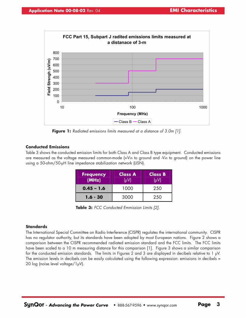
Conducted EmissionsTable 3 shows the conducted emission limits for both Class A and Class B type equipment. Conducted emissionsare measured as the voltage measured common-mode (+Vin to ground and -Vin to ground) on the power lineusing a 50-ohm/50-µH line impedance stabilization network (LISN).
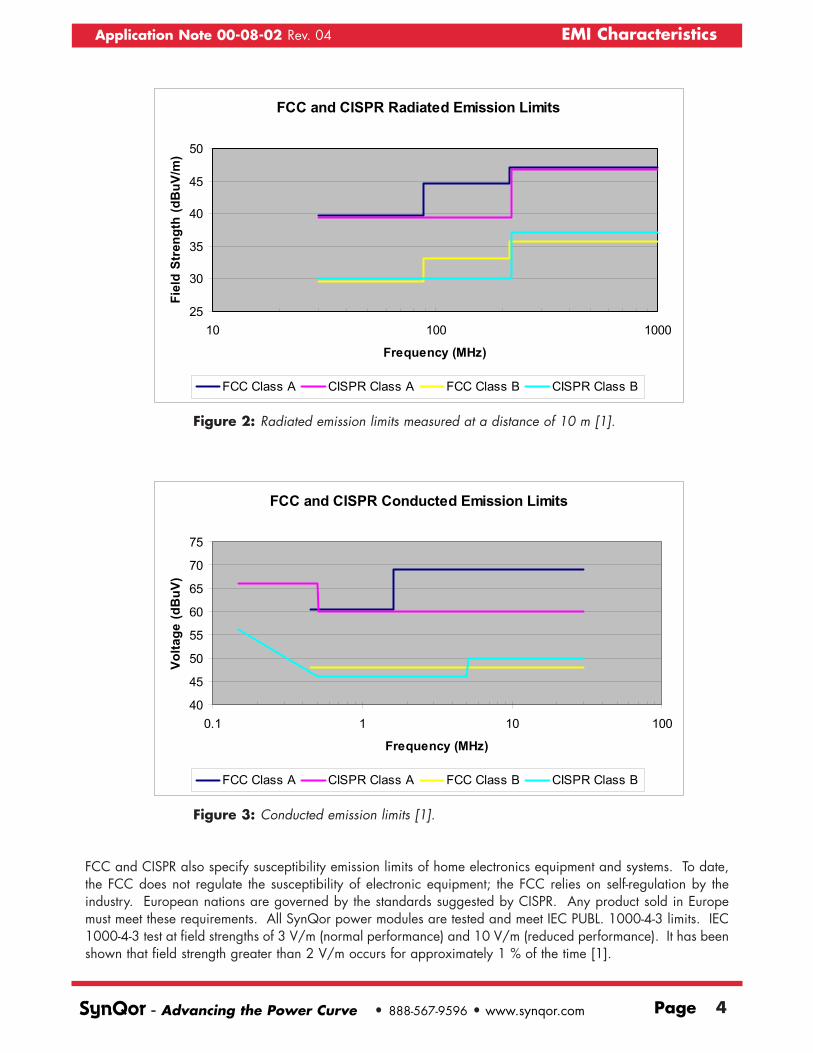
StandardsThe International Special Committee on Radio Interference (CISPR) regulates the international community. CISPRhas no regulator authority, but its standards have been adopted by most European nations. Figure 2 shows acomparison between the CISPR recommended radiated emission standard and the FCC limits. The FCC limitshave been scaled to a 10 m measuring distance for this comparison [1]. Figure 3 shows a similar comparisonfor the conducted emission standards. The limits in Figures 2 and 3 are displayed in decibels relative to 1 µV.The emission levels in decibels can be easily calculated using the following expression: emissions in decibels =20 log (noise level voltage/1µV).
SynQor - Advancing the Power Curve • 888-567-9596 • www.synqor.com Page 3
Application Note 00-08-02 Rev. 04 EMI Characteristics
Figure 1: Radiated emissions limits measured at a distance of 3.0m [1].
FCC Part 15, Subpart J radited emissions limits measured at a distanace of 3-m
0100200300400500600700800
10 100 1000
Frequency (MHz)
Fiel
d St
reng
h (u
V/m
)
Class B Class A
Frequency (MHz)
Class A (µV)
Class B (µV)
0.45 – 1.6 1000 250
1.6 - 30 3000 250
Table 3: FCC Conducted Emmission Limits [2].
FCC and CISPR also specify susceptibility emission limits of home electronics equipment and systems. To date,the FCC does not regulate the susceptibility of electronic equipment; the FCC relies on self-regulation by theindustry. European nations are governed by the standards suggested by CISPR. Any product sold in Europemust meet these requirements. All SynQor power modules are tested and meet IEC PUBL. 1000-4-3 limits. IEC1000-4-3 test at field strengths of 3 V/m (normal performance) and 10 V/m (reduced performance). It has beenshown that field strength greater than 2 V/m occurs for approximately 1 % of the time [1].
SynQor - Advancing the Power Curve • 888-567-9596 • www.synqor.com Page 4
Application Note 00-08-02 Rev. 04 EMI Characteristics
Figure 2: Radiated emission limits measured at a distance of 10 m [1].
FCC and CISPR Radiated Emission Limits
25
30
35
40
45
50
10 100 1000
Frequency (MHz)
Fiel
d St
reng
th (d
BuV
/m)
FCC Class A CISPR Class A FCC Class B CISPR Class B
Figure 3: Conducted emission limits [1].
FCC and CISPR Conducted Emission Limits
40
45
50
55
60
65
70
75
0.1 1 10 100
Frequency (MHz)
Volta
ge (d
BuV
)
FCC Class A CISPR Class A FCC Class B CISPR Class B
Another standard that is sometimes relevant is the EN300 386-2. This standard is relevant only for telecommu-nications equipment and it applies to equipment with either AC or DC power mains. For systems with DC inputmains the EN300 386-2 standard specifies levels identical to the one specified by CISPR Class A limits.However, the EN300 386-2 standard extends to lower frequencies (20 kHz - 150 kHz). All of the SynQorpower modules operate with switching frequencies in excess of 150 kHz. Therefore, typical power modules donot affect the low frequency emission levels of the system.
3.0 EMC For Power ModulesThe first step in tackling the EMI problem is a thorough understanding of the requirements and how it relates toyour system. Remember, there are no conducted or radiated emission restrictions that apply to power modulesas a stand-alone product. Power modules are considered one of many components of modern telecom or com-puter equipment. The requirements apply to the system. The end product must meet a set of conducted and radi-ated emission levels that depends on the equipment usage and country into which it is being sold. Due to thefact that EMI is a system level requirement, it is not practical nor economical for high-power modules to meeteither the conducted and radiated limits as a stand-alone component. Most high-power modules supplied bySynQor or any other manufacturer will probably not comply with the conducted and radiated limits specified bythe different standards without some effort in the design of the system to limit noise.
3.1 Conducted EMIMost electronic equipment has only one interface with the power source. It is at this interface that the conduct-ed emission standards apply. In most applications, power modules are usually isolated from the main powersource by EMI filters, circuit breakers, fuses, transient protection devices, DC/DC converters, and/or AC/DCpower converters. Therefore, in most applications the conducted emissions radiating from the power-module donot appear directly at the power mains. It is very possible that the system will meet the conducted EMI limitswithout any of the power modules meeting the EMC standard as a stand-alone component. Many systems willmeet all EMI standards by simply using a single EMI filter at the input of the power mains.
AC/DC and DC/DC converters by nature generate significant levels of both conducted and radiated noise.Furthermore, if these noises are not suppressed close to the source, they can very easily couple to other areasof the system, greatlyincreasing the complexityof the problem.Therefore, it is recom-mended to have somelevel of EMI suppressionlocal to each power mod-ule.
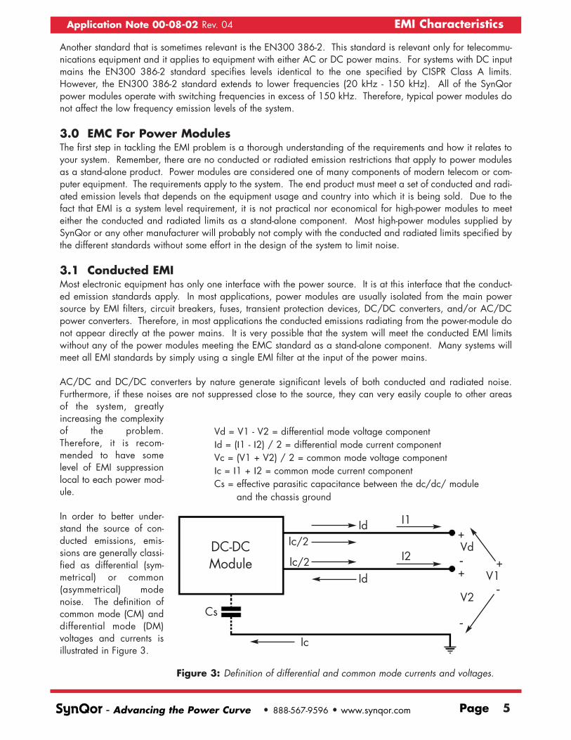
In order to better under-stand the source of con-ducted emissions, emis-sions are generally classi-fied as differential (sym-metrical) or common(asymmetrical) modenoise. The definition ofcommon mode (CM) anddifferential mode (DM)voltages and currents isillustrated in Figure 3.
SynQor - Advancing the Power Curve • 888-567-9596 • www.synqor.com Page 5
Application Note 00-08-02 Rev. 04 EMI Characteristics
Figure 3: Definition of differential and common mode currents and voltages.
Vd = V1 - V2 = differential mode voltage componentId = (I1 - I2) / 2 = differential mode current componentVc = (V1 + V2) / 2 = common mode voltage componentIc = I1 + I2 = common mode current componentCs = effective parasitic capacitance between the dc/dc/ module
and the chassis ground
DC-DCModule
Cs
Ic
Id
IdIc/2
I1
I2Vd
V1
V2
+
-
-
-
+
+Ic/2

The natural operation of dc/dc converters results in differential mode type currents and voltages. SynQor hasadded an input filter to all of its power modules to decrease the DM noise emitted by the converter. The com-mon mode noise emitted by the module cannot be directly determined since there is no direct coupling mecha-nism. The common mode current level is directly related to the effective parasitic capacitance between the powermodule and chassis ground. SynQor's power modules utilize an open frame design with no baseplate and nochassis ground connection. Not having a baseplate greatly reduces the effective capacitance between the mod-ule and chassis ground. Therefore, common mode currents are greatly reduced relative to typical power mod-ules.
Figures 4 and 5 show a comparison of how the SynQor power modules differ from the traditional dc/dc mod-ule relative to their coupling mechanism for common mode emissions. Both of these figures present a simplifiedversion of the common mode emissions problem in dc/dc modules. It is well known that there are many differ-ent coupling mechanisms between the power module and chassis ground. But at the same time as power sup-ply designers, we recognize that the semiconductor devices in conjunction with the power transformer representthe major sources of common mode voltages and currents. Figure 4 shows the traditional implementation ofhigh-power dc/dc modules. Capacitance Cs1 represents the effective parasitic capacitance between the base-plate and chassis ground. Capacitance Cs1 is usually very small, its value is directly related to the size of thebaseplate, the proximity of the baseplate to chassis ground, and the size and shape of the chassis ground. Inmany high-power modules the baseplate is directly connected to chassis ground shorting capacitance Cs1.Capacitance Cs2 is the parasitic capacitance between the semiconductor devices and the baseplate. In orderto maximize the thermal performance of the module, in the traditional solution, a very thin thermal pad sepa-rates the "tab" of the semiconductor devices and the baseplate. This type of construction results in significantparasitic capacitance between the semiconductors and the baseplate. Capacitance Cs2 provides an easy cou-pling mechanism for common mode currents to flow into the chassis ground, especially when the baseplate isconnected to chassis ground.
SynQor - Advancing the Power Curve • 888-567-9596 • www.synqor.com Page 6
Application Note 00-08-02 Rev. 04 EMI Characteristics
Figure 4: Traditional physical design for high power dc/dc modules.
Baseplate
Baseplate
Cs2
Cs1
SemiconductorDevices
Thermal Pad
Cs1 - parasitic capacitance between baseplate and chassis
Cs2 - parasitic capacitance between semiconductor and baseplate
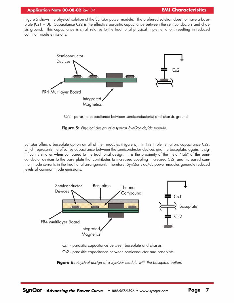
Figure 5 shows the physical solution of the SynQor power module. The preferred solution does not have a base-plate (Cs1 = 0). Capacitance Cs2 is the effective parasitic capacitance between the semiconductors and chas-sis ground. This capacitance is small relative to the traditional physical implementation, resulting in reducedcommon mode emissions.
SynQor offers a baseplate option on all of their modules (Figure 6). In this implementation, capacitance Cs2,which represents the effective capacitance between the semiconductor devices and the baseplate, again, is sig-nificantly smaller when compared to the traditional design. It is the proximity of the metal "tab" of the semi-conductor devices to the base plate that contributes to increased coupling (increased Cs2) and increased com-mon mode currents in the traditional arrangement. Therefore, SynQor's dc/dc power modules generate reducedlevels of common mode emissions.
SynQor - Advancing the Power Curve • 888-567-9596 • www.synqor.com Page 7
Application Note 00-08-02 Rev. 04 EMI Characteristics
Figure 5: Physical design of a typical SynQor dc/dc module.
Cs2
SemiconductorDevices
IntegratedMagnetics
FR4 Multilayer Board
Figure 6: Physical design of a SynQor module with the baseplate option.
Cs1
Cs2
SemiconductorDevices
ThermalCompound
IntegratedMagnetics
FR4 Multilayer Board
Baseplate
Baseplate
Cs2 - parasitic capacitance between semiconductor(s) and chassis ground
Cs1 - parasitic capacitance between baseplate and chassis
Cs2 - parasitic capacitance between semiconductor and baseplate

Table 4 summarizes the EMC related characteristics of selected SynQor modules. Please consult the individualdatasheet for specific data on each module. The switching frequency is listed to help understand the noise spec-trum and help in the design of an external filter. It is important to note that the switching frequency of the mod-ules has a tolerance of +/- 17 % over temperature. The table summarizes the characteristics of the input filter.Most modules have a Pi type filter at the input. C1 is the capacitance connected directly at the input pins. C2is the second capacitor of the Pi filter. In all of the SynQor modules, the inductor is located in the +Vin lead.
Figures 7, and 8 show the conducted emissions of the 25A quarter-brick and the 50A half-brick 3.3V modulesoperating at full load with the aid of an external filter. The modules were tested in an independent Lab (KTL ofDallas) in accordance with the accepted CISPR standards. The modules were loaded with a passive resistiveload to avoid any possible interaction between the "dynamic load" and the module. The units were mountedon a four layer test board where the bottom layer was used for a chassis ground plane. The results show peakmeasurements relative to the average Class B (CISPR) limits. The implementation of the two external filters usedis summarized in Figure 9. The suggested filters allow for the modules to meet CISPR Class B conducted emis-sions limits. Capacitors CYS1 and CYS2 are added to minimize the electromagnetic interference emanatingfrom the output cables in the 5 to 30 MHz frequency range. These capacitors could be omitted if the output dis-tribution bus is relatively short in length.
SynQor - Advancing the Power Curve • 888-567-9596 • www.synqor.com Page 8
Application Note 00-08-02 Rev. 04 EMI Characteristics
Table 4: EMC characteristics of the SynQor power modules. Refer to individual technicaldatasheets for information on specific modules.
Module Type
Nominal Operating Frequency
(kHz)
Input Filter Input
Capacitance C1, C2 (µF)
Input Inductor
(µH)
PQ48150QGA06NNS 270 2nd order 0, 2.46 4.7
PQ48120QGA08NNS 215 2nd order 0, 2.46 4.7
PQ48060QGA17NNS 215 2nd order 0, 2.46 4.7
PQ48050QGA20NNS 300 2nd order 0, 2.46 4.7
PQ48033QGA25NNS 240 2nd order 0, 2.46 4.7
PQ48025QGA25NNS 200 2nd order 0, 2.46 4.7
PQ48020QGA25NNS 270 2nd order 0, 2.46 4.7
PQ48018QGA25NNS 240 2nd order 0, 2.46 4.7
PQ48015QGA25NNS 200 2nd order 0, 2.46 4.7
PQ48050HTA33NNS 200 Pi 1.64, 3.28 4.1
PQ48033HTA50NNS 260 Pi 1.64, 3.28 4.1
PQ48025HTA60NNS 200 Pi 1.64, 3.28 4.1
PQ48020HTA60NNS 200 Pi 1.64, 3.28 4.1
PQ48018HTA60NNS 200 Pi 1.64, 3.28 4.1
PQ48015HTA60NNS 260 Pi 1.64, 3.28 4.1

SynQor - Advancing the Power Curve • 888-567-9596 • www.synqor.com Page 9
Application Note 00-08-02 Rev. 04 EMI Characteristics
Figure 7a: Conducted emission from 150 kHz to 600 kHz for the 25A quarter-brick using theEMI filter shown in Figure 9a [6]. The data shown corresponds to the emission meas-ured in the positive input lead. The 50-dBµV level is shown as a reference.
Figure 7b: Conducted emission from 500 kHz to 30 MHz for the 25A quarter-brick using theEMI filter shown in Figure 9a [6]. The data shown corresponds to the emission meas-ured in the positive input lead. The 50-dBµV level is shown as a reference.

SynQor - Advancing the Power Curve • 888-567-9596 • www.synqor.com Page 10
Application Note 00-08-02 Rev. 04 EMI Characteristics
Figure 8a: Conducted emission from 150 kHz to 600 kHz for the 50A half-brick using the EMIfilter shown in Figure 9b [6]. The data shown corresponds to the emission measuredin the positive input lead. The 60-dBµV level is shown as a reference.
Figure 8b: Conducted emission from 500 kHz to 30 MHz for the 50A half-brick using the EMIfilter shown in Figure 9b [6]. The data shown corresponds to the emission measuredin the positive input lead. The 60-dBµV level is shown as a reference.

SynQor - Advancing the Power Curve • 888-567-9596 • www.synqor.com Page 11
Application Note 00-08-02 Rev. 04 EMI Characteristics
Figure 9a: External filter used with the PQ48033QGA25NNS (quarter-brick 25A/3.3V)power module.
Figure 9b: External filter used with the PQ48033HTA50NNS (half-brick 50A/3.3V)power module.
Filter Mod. # 4
Filter Mod. # 5
Rload
CYS1CY1
CY1 = CY2 = CYS1 =CYS2 = 2700 pF / 2000V ceramic capacitor from AVXCD1 = CD2 = 3 x 1µF /100V ceramic capacitor from AVXL1 = inductor (Pulse part# P0422)CE = 33µF /100V electrolytic capacitor, Refer to “Input System Instability” application note for details.Iout = 25 Amps
CY2
CE
CE
CD1CD2
L1
CYS2
35 -
75Vd
c
PQ48033QGA25NNS
DC/DC Converter
Rload
CYS1CY1
CY1 = CY2 = CYS1 =CYS2 = 2700 pF / 2000V ceramic capacitor from AVXCD1 = CD2 = CD3 = 2 x 1µF /100V ceramic capacitor from AVXL1 = inductor (Pulse part# P0353)CE = 33µF /100V electrolytic capacitorIout = 50 Amps
CY2
CD1
CD2CD3
L1L2
CYS2
35 -
75Vd
c
PQ48033HTA50NNS
DC/DC Converter
3.2 Radiated EMIAgain it is important to remember that only the system needs to meet the required standards. Radiated emis-sions are of importance in the 30 MHz to 1000 MHz range. Metal enclosures in addition to power and groundplanes provide significant attenuation to electromagnetic emissions in the frequency range in question.Therefore, most physical system solutions will provide enough attenuation and allow the system to meet radiat-ed emission standards with relative ease. It is neither practical nor economical to demand the typical dc/dcmodule to meet radiated EMC standards as a stand-alone product.
A one-piece metal "box" with no opening or cracks would be the ideal shield to radiated noise, but this is nota practical solution. When designing for radiated emissions it is important to minimize the size of any openingin the chassis box. The size of any opening in addition to its location relative to the source of radiated EMI isof great importance as it concerns radiated EMI. Furthermore, any location where two or more metal pieces ofthe chassis box meet needs to make electrical contact to maintain the integrity of the shield.
Again, radiated emissions are classified into differential and common mode depending on the source.Differential-mode noise radiates from small loop antennas. Loop antennas can be defined as the area enclosedby a current carrying loop. The magnitude of the field is proportional to the magnitude of the current, theenclosed area, and the square of the oscillating frequency. Reducing the area enclosed by any current loop caneasily minimize differential-mode noise. Great care has been taken in the layout of all SynQor power modulesto reduce differential mode radiation.
On the other hand, common-mode radiation is harder to control and usually determines the overall radiated emis-sion performance of the product. Common-mode radiation usually emanates from the input and output cables.Due to their relatively long length, input and output mains are good transmitters of EMI noise. Input and outputcables behave as monopole antennas driven by a voltage. Decoupling both input and output mains with ceram-ic capacitors to chassis ground close to the power module suppresses the excitation voltage. Great care has tobe taken not to exceed the leakage current requirement (this is a safety requirement) when adding capacitorsfrom any point to chassis ground in systems powered by an AC distribution.
For reference, Table 5 shows radiated emissions levels for a 25A quarter-brick 3.3Vout module operating at fullload. The module was tested with the external filter suggested in Figure 9a in place. Again, a resistive loadbank was used to obtain these results. The tables show peak measurements of the radiated emissions levels rel-ative to the average Class B limits as suggested by CISPR. The data shows that the module and filter combina-tion fails CISPR Class B emissions standards by only a few dBs. The module was tested in an outdoor inde-pendent test facility at KTL of Dallas.
The conducted and radiated emissions levels reported for the different modules should be used as a referenceonly. The emissions levels are very dependent on the physical configuration and grounding practices of the sys-tem under test.
SynQor - Advancing the Power Curve • 888-567-9596 • www.synqor.com Page 12
Application Note 00-08-02 Rev. 04 EMI Characteristics

SynQor - Advancing the Power Curve • 888-567-9596 • www.synqor.com Page 13
Application Note 00-08-02 Rev. 04 EMI Characteristics
Frequency (MHz)
Antenna Polarization
Reading (dBµV/m)
Class B limit (dBµV/m)
Diff. (dB)
Type of Measurement
30.17 H 30.9 30.0 0.9 Peak 30.66 H 1.929.7 30.0 -0.3 Peak 36.20 H 1.637.1 30.0 7.1 Peak 37.71 H 37.8 30.0 7.8 Peak 48.76 H 28.7 30.0 -1.3 Peak 52.03 H 31.2 30.0 1.2 Peak 86.46 H 23.4 30.0 -6.6 Peak
108.80 H 27.5 30.0 -2.5 Peak 141.28 H 43.5 30.0 13.5 Peak 142.80 H 43.5 30.0 13.5 Peak 160.38 H 32.8 30.0 2.8 Peak 165.13 H 32.5 30.0 2.5 Peak 208.90 H 29.2 30.0 -0.8 Peak 221.90 H 27.4 30.0 -2.6 Peak 228.48 H 28.1 30.0 -1.9 Peak
36.20 V 48.2 30.0 18.2 Peak 36.20 V 32.4 30.0 2.4 Quasi-Peak 37.75 V 48.0 30.0 18.0 Peak 37.75 V 32.4 30.0 2.4 Quasi-Peak 50.30 V 40.5 30.0 10.5 Peak 50.30 V 25.5 30.0 -4.4 Quasi-Peak 52.03 V 36.3 30.0 6.3 Peak 62.84 V 33.8 30.0 3.8 Peak 74.60 V 28.2 30.0 -1.8 Peak 85.96 V 31.1 30.0 1.1 Peak
119.13 V 35.5 30.0 5.5 Peak 125.40 V 36.1 30.0 6.1 Peak 142.50 V 41.8 30.0 11.8 Peak 142.50 V 32.3 30.0 2.3 Quasi-Peak 144.00 V 42.4 30.0 12.4 Peak 144.00 V 32.4 30.0 2.4 Quasi-Peak 165.10 V 30.1 30.0 0.1 Peak 208.80 V 28.1 30.0 -1.9 Peak 224.90 V 26.3 30.0 -3.7 Peak
302.57 H 26.0 37.0 -11.0 Peak 343.57 H 27.8 37.0 -9.2 Peak 377.50 H 25.1 37.0 -11.9 Peak
301.87 V 23.0 37.0 -14.0 Peak 334.08 V 19.9 37.0 -17.1 Peak 438.00 V 22.6 37.0 -14.4 Peak
Table 5: Radiated emissions of a 25A Quarter-brick 3.3V module with the external filtershown in Figure 9a.

4.0 Layout and Grounding PracticesGreat care should be taken in the layout and grounding practices used for the module and system in general.A list of suggestions that will minimize conducted and radiated emissions include:
1. Add both, low frequency tantalum and high frequency ceramic capacitors to the dc/dcmodule output bus. Place at least one of each as close as possible to the output termi-nals of the module.
2. Add both, low frequency electrolytic and high frequency ceramic capacitor to the dcinput distribution bus. Place at least one of each as close as possible to the input ter-minals of the module.
3. Use short leads on all filter and decoupling components. Minimize all circuit loops thatcarry significant current.
4. Minimize parasitic inductances by using wide distribution traces over ground planes.
5. Place a Y-capacitor between input and output ground planes. Return all common modenoise to the input ground.
Additional details about all of these topics can be found in [1,4].
5.0 References[1] Ott, Henry, W., Noise Reduction Techniques in Electronic Systems, Second Edition, John Wiley & Sons, NewYork, 1988.
[2] Code of Federal Regulations, Title 47 (47CFR). Part 15, Subpart J. "Computing Devices."
[3] CISPR, Publication 22. "Limits and Methods of Measurements of Radio Interference Characteristics ofInformation Technology Equipment," 1985.
[4] Thihanyi, Laszlo, Electromagnetic Compatibility in Power Electronics, 10th edition, J. K. Eckert & Company,Inc., Sarasota, Florida, 1995.
[5] Ferreira, J.A., Winlock, P.R., and Holm, S.R., "Sources, Paths and Traps of Conducted EMI in Switch ModeCircuits,"
[6] KTL Engineering test report # 0L0073EUS
SynQor - Advancing the Power Curve • 888-567-9596 • www.synqor.com Page 14
Application Note 00-08-02 Rev. 04 EMI Characteristics
155 Swanson Rd., Boxboro, MA 01719 Phone: 978-849-0600
Toll Free: 888-567-9596Fax: 978-849-0602
Web: www.synqor.come-mail: [email protected]: 065-0000004-PDF Author: Richard Farrington