Embed Size (px)
Citation preview

1146 IEEE TRANSACTIONS ON MICROWAVE THEORY AND TECHNIQUES, VOL. 51, NO. 4, APRIL 2003
An Efficient Numerical Interface Between FDTD andHaar MRTD—Formulation and Applications
Costas D. Sarris, Member, IEEE,and Linda P. B. Katehi, Fellow, IEEE
Abstract—A hybrid finite-difference time-domain (FDTD)/Haarmultiresolution time-domain (MRTD) technique for the time-do-main analysis of microwave structures is proposed in this paper.The salient features of the presented algorithm are, first, its in-herent stability that stems from the matching of the dispersionproperties of FDTD and Haar MRTD and, second, its applicabilityto arbitrarily high wavelet order MRTD schemes. Thus, the ap-plication of the MRTD technique to the modeling of open struc-tures and inhomogeneous circuit geometries is facilitated. In par-ticular, the straightforward implementation of perfectly matchedlayer type and Mur’s absorbing boundary conditions is attained.The fact that the proposed interface involves no spatial or temporalinterpolations or extrapolations indicates its potential to efficientlyconnect FDTD and Haar MRTD.
Index Terms—Finite-difference time-domain (FDTD), multi-resolution analysis, multiresolution time-domain (MRTD).
I. INTRODUCTION
T HE time-domain characterization of microwave struc-tures, often encountered in wireless front-end applications
such as filter, resonator, or feed components, usually includesthe modeling of fine detail complex boundaries and regions ofdynamically varying field distributions [1]. For this purpose,dense gridding conditions are necessary for the extraction ofan accurate solution to the problem at hand. Nevertheless, theimplementation of a uniformly dense mesh for an electricallylarge structure translates to computationally burdensome simu-lations, as a result of both the size of the domain (in cells) andthe stability-related restriction on the time step of a finite-dif-ference time-domain (FDTD) type of scheme, imposed by thesmall dimensions of the unit cell. Hence, the incorporation oflocal mesh refinement techniques into conventional time-do-main solvers is motivated as a means of alleviating the overallcost of modeling structures with localized geometric details.
Standard subgridding techniques involve spatio-temporal in-terpolations or extrapolations at the boundaries of different res-olution parts of the numerical grid [2], [3] that render the rig-
Manuscript received March 3, 2002; revised December 2, 2002. This workwas supported by the U.S. Army Communications and Electronics Commandand by the Department of Defense High-Performance Computing Moderniza-tion Program under the “Efficient Numerical Solutions to Large Scale TacticalCommunication Problems” Project DAAD19-00-1-0173.
C. D. Sarris was with the Radiation Laboratory, Department of ElectricalEngineering and Computer Science, University of Michigan at Ann Arbor, AnnArbor, MI 48109-2122 USA. He is now with the E. S. Rogers Sr. Departmentof Electrical and Computer Engineering, University of Toronto, Toronto, ON,Canada M5S 3G4.
L. P. B. Katehi was with the Radiation Laboratory, Department of ElectricalEngineering and Computer Science, University of Michigan at Ann Arbor, AnnArbor, MI 48109-2122 USA. She is now with the Department of Electrical andComputer Engineering, Purdue University, West Lafayette, IN 47097 USA.
Digital Object Identifier 10.1109/TMTT.2003.809620
Fig. 1. Coarse rectangular mesh for a layered coplanar-waveguide structurewith cells containing variable dielectric permittivity and electric conductivityprofiles.
orous enforcement of the divergence-free nature of the magneticfield and the continuity conditions a rather subtle issue. Fur-thermore, a higher order static subgridded FDTD algorithm thatneeds no interpolatory operations has been recently proposed in[4]. However, as time-domain simulations of microwave geome-tries typically register the history of a wide-band pulse propaga-tion along a computational domain, adaptively imposing densegridding conditions only in and around the pulse and the prod-ucts of its retro-reflections can further extend the efficiency of atechnique. Thus, if allowing for a relatively coarse mesh is onechallenge that novel numerical schemes are expected to meet,a second, but equally important one, is adaptivity, translating tothe possibility of dynamic mesh refinement at regions of the do-main that are electromagnetically active at a certain time step.
Wavelet-based numerical algorithms stemming from the mul-tiresolution time-domain (MRTD) technique [5] offer a naturalframework for the implementation of dynamic mesh refinementin the sense demonstrated in [6]. For homogeneous domains,the computational efficiency of the former is expected to in-crease with the order of the multiresolution expansion. Yet, thecomplexity of conductor, dielectric, and boundary modeling thatthey present, also increasing with wavelet order, seriously com-promises their potential applicability to state-of-the-art devices.In particular, whenever a single cell includes variable materialproperties (such as dielectric and/or conducting layers), directMRTD update equations are replaced by matrix expressions, re-sulting from the discretization of constitutive relations [5], [13].These cases are encountered in typical microwave devices suchas microstrip lines and coplanar waveguides (Fig. 1). In addi-tion, the most effective mesh truncation technique today, theperfectly matched layer (PML) absorber, is itself an inhomo-geneous uniaxially anisotropic (both electrically and magneti-cally) material.
The aforementioned contradiction was addressed by the au-thors in [7] and [8] by means of a hybrid approach that con-nected the FDTD technique with the Haar wavelet-based MRTDvia a numerical interface. The purpose of this approach was to
0018-9480/03$17.00 © 2003 IEEE

SARRIS AND KATEHI: EFFICIENT NUMERICAL INTERFACE BETWEEN FDTD AND HAAR MRTD 1147
establish an efficient algorithm, allowing for the combinationof the versatility of FDTD with the adaptivity of MRTD, em-ploying the first in geometrically complex parts of the domainand the second in homogeneous regions. This paper presents theideas of [8] in greater extent.
In the past, interfaces between different numerical methodshave been developed in order to address specific problems of in-terest. In [9], the frequency-domain method of moments (MoM)was coupled to the FDTD technique for the analysis of groundpenetrating radar (GPR) problems, where GPR antenna opera-tion wasmodeled by the MoM, while the inhomogeneous ground(including dielectric stratification) was incorporated in an FDTDmesh. In [10], a Daubechies scaling-function-based wavelet-Galerkin scheme was coupled to FDTD for the modeling ofwedge loaded two-dimensional waveguide structures, appar-ently leading to significant computational savings compared toits pure FDTD counterpart. Still, the general applicability andefficiency of the scheme was questionable, given the largely dif-ferent dispersion characteristics of the two methods. Moreover,a hybridization of the transmission line matrix (TLM) methodand MRTD was pursued in [11], where the issue of dealing withdisparate dispersion methods was explicitly addressed via aconditionally stable space–time interpolation scheme. Finally,[12] demonstrated a technique for including FDTD-modeledlumped elements in a three-dimensional domain simulated bythe Haar wavelet-based MRTD formulation that was introducedin [13] and was restricted to one wavelet level.
This paper proposes an interface between a Haar waveletMRTD scheme of an arbitrary number of wavelet levelsand FDTD technique. Under certain conditions, which arementioned in [14], the two schemes are characterized by thesame dispersion properties; a fact that is utilized in order tocouple them with no interpolations or extrapolations and withabsolutely no spurious reflections at their interface. This paperis organized as follows. First, the formulation of an arbitrary-order Haar MRTD scheme is presented. Noting that the dis-persion equation for the latter coincides with the dispersionequation of an FDTD scheme of the same spatial resolution,a simple connection algorithm between the two is proposed.Emphasis is placed on the implementation problems that arisein the application of update equations at the boundaries of thetwo domains. Validation studies include the analysis of two-dimensional dielectric cavity structures under various FDTD/MRTD mesh configurations. Finally, the method is applied formesh truncation in open-domain problems and the modeling ofstructures with metal inserts such as a fin-loaded cavity.
II. TWO-DIMENSIONAL HYBRID ARBITRARY ORDER HAAR
MRTD/FDTD SCHEME: FORMULATION
A. MRTD, FDTD Equations
A two-dimensional system of the following Maxwell’s equa-tions corresponding to waves:
(1)
(2)
(3)
with is considered and discretized throughthe MoM-based technique of [5]. In the MRTD region, thefield components are expanded in a Haar wavelet basis oforders in the -direction and in the -direc-tion, respectively, the scaling cell size being . Asexplained in [14], if an electric field scaling cell is centeredat , the corresponding scaling cell must becentered at , with , whilethe one at , with . Inthe FDTD region, the field components are expanded in a pulsebasis, introducing the cell dimensions ,
. For example, the expansion in the MRTD regionis cast in the form
(4)
where the standard definitions (given, for example, in [14]) havebeen used for the Haar scaling and wavelet functions, ,and the pulse functions(which compose the temporal basis ofthe method). In the FDTD region, is written as
where the definition of theth-order scaling functionwith has been adopted. The
use of Haar wavelets in the MRTD region effectively divideseach scaling cell into subcells of size
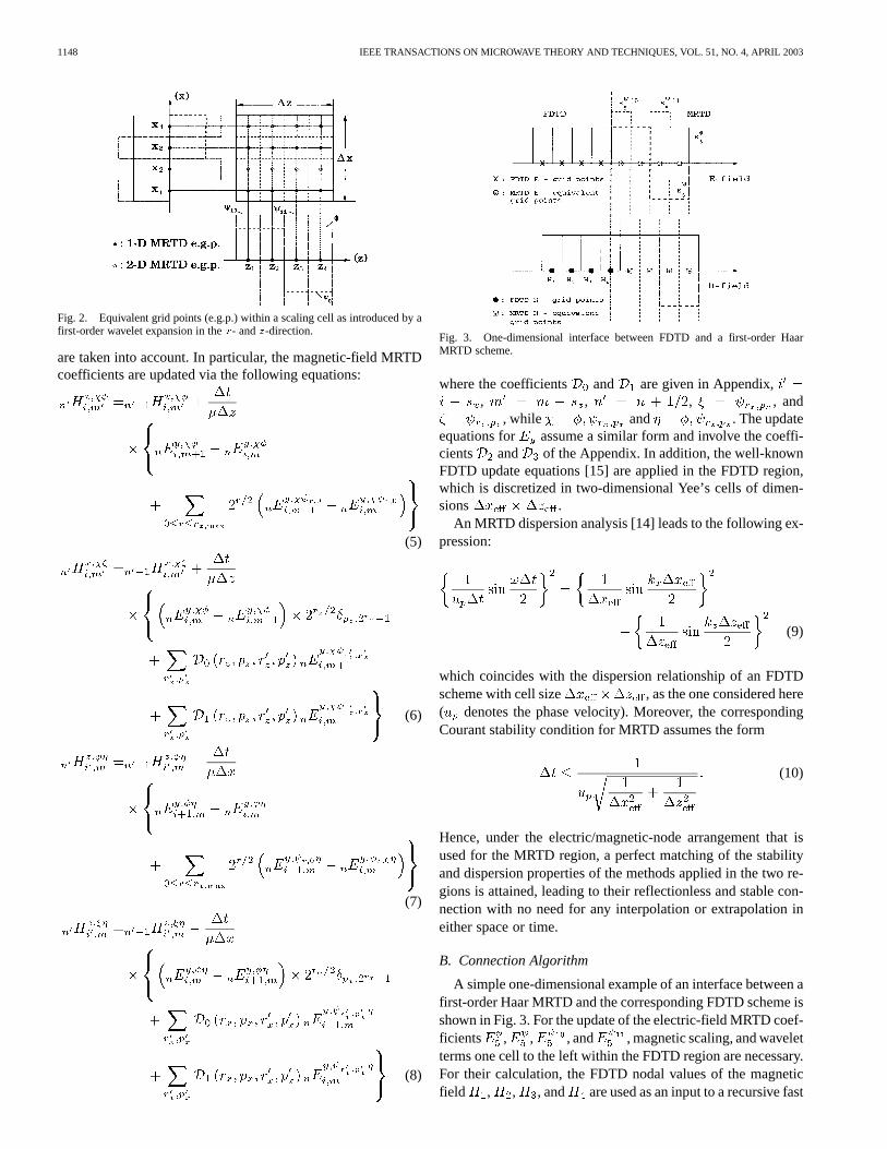
by , in the sense shown in Fig. 2, where the caseof a first-order scheme (with two wavelet levels) in both the-and -direction scheme is depicted. The MRTDequivalent gridpointsare grid nodes, where field values are computed as linearcombinations of the scaling and wavelet terms that appear in (4).A matrix formulation that further illustrates the computation ofnodal field values at the equivalent grid points from the coeffi-cients of (4) is provided in [13].
Upon substitution of all field component expansions [such as(4)] into Maxwell’s equations (1)–(3), the Galerkin’s method isapplied for the derivation of field update equations. To this end,Haar integral expressions, which are provided in the Appendix,
1148 IEEE TRANSACTIONS ON MICROWAVE THEORY AND TECHNIQUES, VOL. 51, NO. 4, APRIL 2003
Fig. 2. Equivalent grid points (e.g.p.) within a scaling cell as introduced by afirst-order wavelet expansion in thex- andz-direction.
are taken into account. In particular, the magnetic-field MRTDcoefficients are updated via the following equations:
(5)
(6)
(7)
(8)
Fig. 3. One-dimensional interface between FDTD and a first-order HaarMRTD scheme.
where the coefficients and are given in Appendix,, , , , and
, while and . The updateequations for assume a similar form and involve the coeffi-cients and of the Appendix. In addition, the well-knownFDTD update equations [15] are applied in the FDTD region,which is discretized in two-dimensional Yee’s cells of dimen-sions .
An MRTD dispersion analysis [14] leads to the following ex-pression:
(9)
which coincides with the dispersion relationship of an FDTDscheme with cell size , as the one considered here( denotes the phase velocity). Moreover, the correspondingCourant stability condition for MRTD assumes the form
(10)
Hence, under the electric/magnetic-node arrangement that isused for the MRTD region, a perfect matching of the stabilityand dispersion properties of the methods applied in the two re-gions is attained, leading to their reflectionless and stable con-nection with no need for any interpolation or extrapolation ineither space or time.
B. Connection Algorithm
A simple one-dimensional example of an interface between afirst-order Haar MRTD and the corresponding FDTD scheme isshown in Fig. 3. For the update of the electric-field MRTD coef-ficients , , , and , magnetic scaling, and waveletterms one cell to the left within the FDTD region are necessary.For their calculation, the FDTD nodal values of the magneticfield , , , and are used as an input to a recursive fast

SARRIS AND KATEHI: EFFICIENT NUMERICAL INTERFACE BETWEEN FDTD AND HAAR MRTD 1149
Fig. 4. Reflectionless propagation through a one-dimensional FDTD/fourth-order MRTD interface.
wavelet transform (FWT). Thus, the wavelet decomposition ofthe magnetic field at that cell is deduced and employed for theelectric-field updates of MRTD at the FDTD/MRTD boundary.In the case of an FDTD to MRTD transition, an inverse fastwavelet transform (IFWT) is applied to derive FDTD coeffi-cients (nodal field values) from MRTD terms. It is noted thatboth the FWT and IFWT are characterized by an optimal com-plexity of . In addition, their computational implementa-tion is relatively simple.
As a computational validation of these interface principles,the propagation of a 0–5-GHz Gaussian pulse through anFDTD/fourth-order MRTD interface is shown in Fig. 4. Thecell size for the FDTD region (andeffectivecell size for MRTD)is 2.4 mm, while the MRTD scaling cell size is 76.8 mm. Thetime step is 0.9 of the Courant limit. The interface for theelectric-field nodes is located at cell 1440. Smooth and stabletransition from the MRTD to FDTD region is observed, asexpected.
Next, a two-dimensional FDTD/MRTD connection algorithmis presented for the case where an FDTD region encloses anMRTD one. An application of interest for this case is the termi-nation of an MRTD mesh in an FDTD PML absorber, which al-lows for MRTD domain truncation via existing absorber codes.Similar concepts can be employed for interfaces of other types.
To begin, data transfer from the MRTD to FDTD is addressed.For the update of all FDTD grid points whose stencil extendsinto the MRTD region, it suffices to retrieve the nodal fieldvalues of the electric field one FDTD cell within the MRTDregion (Fig. 5). Thus, the complete determination of the tan-gential electromagnetic-field components across the boundaryof the FDTD domain is allowed for. The independent solutionof this region then becomes possible since the MRTD calculatedtangential fields are used as boundary conditions for FDTD. Inconsequence, the problem is reduced to calculating nodal fieldvalues along the boundary of the MRTD region, which is ex-actly the function of the IFWT (see [16]) that is carried out atthe optimal complexity of .
Conversely, for the update of the MRTD boundary mag-netic-field coefficients, FDTD electric-field nodes extendingover one scaling cell within the FDTD region are wavelettransformed via a FWT routine. If this scaling cell extends
Fig. 5. FDTD update from MRTD data.
Fig. 6. MRTD update from FDTD data.
beyond the domain, zero field values are used. This is possibleand physically correct for both closed- and open-domainproblems, provided that a perfect conductor backed absorberis typically used for the simulation of an open boundary.Fig. 6 schematically explains this procedure for a case where
. It is noted that no FDTD grid points aresought for at the (shaded) corner region shown in Fig. 6. This isdue to the fact that MRTD, just as FDTD, uses a cross-shapedstencil for the update of all grid points. Computing the elec-tric-field MRTD coefficients from the FDTD data via anFWT and updating the tangential magnetic-field componentcoefficients via the standard MRTD finite-difference equationsdetermines, again, the tangential electromagnetic-field compo-nents across the boundary of the MRTD region. This, in turn,is sufficient for its independent MRTD-based solution.
Evidently, all operations that implement this connection al-gorithm are performed at the same time step, during the updateof the electric-field coefficients in both regions, in an absolutelystable fashion, due to the matching of the dispersion propertiesof the two schemes. Furthermore, the same principles lead to in-terfaces between wavelet schemes of an arbitrary basis and theones that are formulated by the corresponding scaling functionsonly, provided that the effective resolutions in the two regionsare kept the same. It is also noted that the extension of the inter-face algorithm to three dimensions is accomplished by treatingeach face of Yee’s cell according to the method that has been setforth in this study.

1150 IEEE TRANSACTIONS ON MICROWAVE THEORY AND TECHNIQUES, VOL. 51, NO. 4, APRIL 2003
Fig. 7. Empty rectangular-cavity geometry and interface of a 3� 3 orderMRTD/FDTD mesh configuration (dimensions are given in FDTD cells, MRTDmesh is 2� 2).
Fig. 8. Time- and frequency-domain patterns of electric field(E ) sampledwithin the cavity of Fig. 7, as obtained by the FDTD and hybrid scheme.
Fig. 9. Empty rectangular-cavity geometry and interface of a 3� 4 orderMRTD/FDTD mesh configuration (dimensions are given in FDTD cells, MRTDmesh is 1� 1).
III. N UMERICAL RESULTS: VALIDATION
Several two-dimensional air-filled square resonators havebeen analyzed in various FDTD/MRTD mesh configurationsfor validation purposes. The choice of those configurations wasmade in order to demonstrate that the stability and accuracyof the algorithm was preserved under any gridding conditions,these being either related to the order of the MRTD scheme orthe proximity of the MRTD region to the hard boundary of thedomain. The dimensions of the cavity structures in all figuresare given in FDTD cells (or MRTDequivalentgrid points).Figs. 7–10 depict two case studies for MRTD/FDTD mesh con-figurations. In the first case (Fig. 7), an MRTD scheme of order3 in both the - and -direction forms a mesh of 2 2 scalingcells corresponding to 32 32 FDTD cells, asymmetricallyplaced within an FDTD region that is terminated into the metalboundaries of the cavity. The whole domain corresponds to
Fig. 10. Time- and frequency-domain patterns of electric field(E ) sampledwithin the cavity of Fig. 9, as obtained by the FDTD and hybrid scheme.
Fig. 11. Empty square-cavity geometry and interface of a 4� 4 orderMRTD/FDTD mesh configuration (dimensions are given in FDTD cells,MRTD mesh is 1� 1).
36 40 FDTD cells of dimension 1 cm 1 cm. A pure MRTDscheme would model these electric walls by means of imagetheory, necessitating the introduction of several images ofhigh-order wavelet terms [5]. On the other hand, enclosing theMRTD region in an FDTD one facilitates the treatment of thesehard boundaries, whose FDTD modeling amounts to settingthe tangential to perfect electric conducting (PEC) electric fieldnodal values equal to zero. Similarly, in the second case, anMRTD scheme of orders 3 and 4 in the- and -direction,respectively, forms a 1 1 scaling mesh and is interfaced withFDTD of cell size 1 cm 1 cm. The total domain correspondsto 20 39 FDTD cells. Cavity resonances that are derived viaa pure FDTD scheme and the proposed interface-based methodagree well (in both the time and frequency domains), as shownin Figs. 8 and 10. In all cases, the time step was set equal to 0.9of the Courant stability limit.
A third validation case is shown in Fig. 11. In that case, theMRTD region is symmetrically placed within the FDTD meshand only two FDTD cells away from the boundary. The MRTDscheme is of order 4 in both directions, hence, giving rise toa single scaling cell mesh in the MRTD region. The effectivecell size is again 1 cm 1 cm and the time step equal to 0.9 ofthe Courant limit. The patterns of the and modes,derived via the interface algorithm, are shown in Figs. 12 and 13.The smooth patterns confirm the correctness of the scheme andthe absence of any type of spurious effects that would corruptits performance. This observation is also in agreement with theHaar MRTD dispersion analysis in [14].

SARRIS AND KATEHI: EFFICIENT NUMERICAL INTERFACE BETWEEN FDTD AND HAAR MRTD 1151
Fig. 12. Electric-field pattern for theTE mode of the empty cavity of Fig. 8(4� 4 MRTD).
Fig. 13. Electric-field pattern for theTE mode of the empty cavity of Fig. 8(4� 4 MRTD).
IV. NUMERICAL RESULTS: APPLICATIONS
A. Metal Fin Loaded Cavity
The method of this paper is applied for the simulation of ametal fin loaded cavity, similar to the one presented in [11]. Thisstructure is chosen for the reason that the presence of the metalfin within the domain restricts the order of the MRTD schemethat can be employed for its analysis. In particular, whenever ascaling cell greater than the fin dimensions is chosen, the utmostcare is necessary for the compensation of the unphysical cou-pling of the regions below and above the fin, which is caused bythe scaling function defining the fin cell (or wavelets extendingbeyond the fin limits). However, the strategies that are followedin this case (e.g., domain split [17]) result in a local increaseof operations and consumption of computational resources andbring about practical implementation problems, especially whenone is interested in developing generic wavelet-based computer-aided design (CAD) tools.
For the interface-based solution of the problem, the griddingconditions are given in Fig. 14. In the MRTD region, a secondby second-order scheme is employed (44 scaling cells). Thetime step is set at 0.8 of the Courant limit and FDTD cells of1 cm 1 cm are used. As an excitation, a Gaussian pulse, withits 3-dB frequency chosen to be equal to , being thecutoff frequency of the mode of the cavity, is applied inthe FDTD region (at the plane cm). Under these con-ditions, a stable performance of the code was obtained. Thededuced electric-field spatial distribution is shown in Fig. 15.Moreover, in order to demonstrate the stability of the solution,
Fig. 14. Metal fin loaded cavity geometry and interface of a 2� 2 orderMRTD/ FDTD mesh configuration (dimensions are given in FDTD cells, MRTDmesh is 4� 4).
Fig. 15. Electric-field distribution in the metal fin loaded cavity (dominant TEmode).
Fig. 16. Electric-field sampled within the fin loaded cavity as a function oftime for time steps 18 000–20 000.
the electric field, sampled at the point ( cm,cm), is plotted as a function of time for an arbitrary interval
of 18 000–20 000 time steps, as shown in Fig. 16. It is noted thatno late-time instabilities were observed over as many as 100 000time steps.
B. PML Mesh Termination for MRTD
A typical problem related to higher order and multiresolu-tion formulations of finite-difference schemes is the inherentlycomplex modeling of boundary and material conditions. Forhigh-order Haar wavelet schemes, a formulation for a matched-layer absorber that was proposed in [18] highlighted the diffi-culty of such efforts that essentially stems from the samplingof varying electric and magnetic conductivities by a multilevelbasis. Furthermore, it may seem necessary that the absorberregion of an MRTD mesh be discretized by at least the de-grees of freedom of a single MRTD cell. However, for high-order schemes, this would lead to absorber regions that are much

1152 IEEE TRANSACTIONS ON MICROWAVE THEORY AND TECHNIQUES, VOL. 51, NO. 4, APRIL 2003
Fig. 17. Concept of MRTD mesh termination via an FDTD/MRTD interface.
Fig. 18. Slab waveguide geometry.
longer than the ones typically used in FDTD applications. Forexample, terminating an MRTD with five wavelet levels (fourth-order scheme) in just a single cell of it is equivalent to using anFDTD absorber of 64 grid points per direction. Nevertheless, ex-cellent performance of just 8–16 cell optimized FDTD-uniaxialperfectly matched layer (UPML) absorbers has been recentlydemonstrated [19], prompting the quest for MRTD absorbersthat may extend over afraction of an MRTD scaling cell.
In this paper, the concept of the FDTD/MRTD interface isemployed for the implementation of a UPML termination of anMRTD domain. In particular, an FDTD-UPML region enclosesan MRTD one and the interface algorithm is applied for the re-flectionless connection of the two. In case the FDTD region cor-responds to a fraction of a scaling cell, the application of MRTDupdate equations needs FDTD grid points beyond the conductorthat backs the PML. The latter are simply zeroed out and fedback as such to the FWT routine. This concept is explained fora one-dimensional case of a second-order MRTD scheme (witheight equivalent grid points per cell) terminated into a four-cellFDTD PML (half a scaling cell), as shown in Fig. 17.
Using this method, the waveguide structure of Fig. 18, alsopresented in [6] and [7], is solved by a fourth-order MRTDscheme, truncated with a six- and eight-grid-point PML corre-sponding to 0.1875 and 0.25 of a scaling cell, which, in thiscase, is 8 mm. A 0–30-GHz Gaussian pulse excitation is used,and the reflection coefficient from the slab is calculated. Thescaling cell is , while the five wavelet levels succes-sively refine the resolution of the scheme to . An impor-tant principle of multiresolution analysis is thus demonstrated.Loss of accuracy and aliasing due to the violation of the Nyquistlimit at the scaling function level is recursively compensated forby the higher order wavelets. Fig. 19 depicts comparative plots
Fig. 19. Numerical and theoreticalS for the slab geometry.
Fig. 20. Unthresholded to the total number (in percentage) of zeroth-orderwavelet coefficients at each time step for a fourth-order Haar MRTD simulationof the problem of Fig. 18.
of the numerical results derived by the two termination types,along with the theoretical form derived by transmission-linetheory. Evidently, all three sets of results are in good correlationwith each other.
Thresholding of Haar wavelet coefficients is applied based onthe condition
where is a predefined threshold. Hence, the amplitude of thethreshold is adapted to the orderof each wavelet coefficientthrough the use of a normalization term . This choice isdue to the fact that the maximum absolute value of the basisfunction is . Thresholding then amounts to omit-ting wavelet terms whose maximum contribution to the fieldvalue is less than. For two different threshold valuesand 10 , the number of wavelet coefficients that are abovethreshold is computed at each time step. The resultant plots forwavelets of orders 0–3 are shown in Figs. 20–23. Evidently, de-spite small differences between them, all four curves have a sim-ilar pattern: Around time-step 2000, unthresholded wavelet co-efficients are doubled as a result of the pulse incidence on thedielectric slab, which generates an additional (reflected) wave-front. The PML absorption of the two wavefronts, symmetri-cally generated by the source in the middle of the domain, then

SARRIS AND KATEHI: EFFICIENT NUMERICAL INTERFACE BETWEEN FDTD AND HAAR MRTD 1153
Fig. 21. Unthresholded to total number (in percentage) of first-order waveletcoefficients at each time step for a fourth-order Haar MRTD simulation of theproblem of Fig. 18.
Fig. 22. Unthresholded to total number (in percentage) of second-orderwavelet coefficients for a fourth-order Haar MRTD simulation of the problemof Fig. 18.
Fig. 23. Unthresholded to total number (in percentage) of third-order waveletcoefficients, at each time step for a fourth-order Haar MRTD simulation of theproblem of Fig. 18.
causes a step-wise decrease in the number of active wavelet co-efficients. Finally, the absorption of the reflected wavefront sig-nals the end of the simulation and the decay of the number ofunthresholded coefficients to almost zero. Overall, thresholdingof wavelet coefficients yields a compression in memory require-ments by 64.6% (in 8192 time steps). It is also noted that, the
Fig. 24. Case study for the interface-based termination of a two-dimensionalMRTD domain.
Fig. 25. FDTD UPML interfaced with a 0� 0 order MRTD (MRTD mesh is32� 32).
Fig. 26. FDTD-UPML interfaced with a 2� 2 order MRTD (MRTD mesh is8� 8).
higher the order of wavelet terms, the higher the number ofsteady-state unthresholded wavelets (that theoretically shouldbe zero). This stems from the fact that high-order wavelets areexcited by numerical errors due to the finite discretization ofthe domain and absorber. This observation presents an ultimatelimit for the efficiency of wavelet methods, but also underlinesthe importance of MRTD mesh termination studies. Obviously,inefficient absorbers produce significant reflection errors thatexcite high-order wavelet terms, keeping them above thresholdeven at late simulation times.
Moreover, a two-dimensional eight-cell UPML with theo-retical reflection coefficient and fourth-orderpolynomial conductivity variation is used to terminate MRTDmeshes that correspond to a 6464 FDTD domain (Fig. 24).The three case studies are depicted in Figs. 25–27 and corre-spond to MRTD orders 0 0, 2 2, and 4 4, respectively. Anelectric-current excitation of the form
(11)

1154 IEEE TRANSACTIONS ON MICROWAVE THEORY AND TECHNIQUES, VOL. 51, NO. 4, APRIL 2003
Fig. 27. FDTD-UPML interfaced with a 4� 4 order MRTD (MRTD mesh is2� 2).
Fig. 28. Comparison of FDTD and MRTD/FDTD interface results for the threecase studies of Figs. 25–27.
with and GHz is applied in the middle ofthe domain. The FDTD cell size is set equal to 2.5 mm2.5 mmand the time step is ps. Time-domain field wave-forms are then sampled at the points indicated as inFigs. 25–27, corresponding to FDTD cells , ,and of the 64 64 domain. The results, shown in Fig. 28,demonstrate an excellent agreement between the pure FDTDscheme and the FDTD-UPML terminated MRTD. It is notedthat the UPML regions in these three examples extend over 4, 1,and 0.25 MRTD cells, respectively, demonstrating the ability ofthe interface to provide MRTD absorbing boundary conditions(ABCs) with efficiency and complexity that are independent ofthe order of the underlying wavelet expansion.
In addition, Fig. 29 depicts the electric-field waveform sam-pled at point of the MRTD domain of Fig. 26 when terminatedat 4, 8, and 16 FDTD-UPML cells (0.5, 1, and 2 MRTD cells,respectively). The same waveform is determined via the FDTDmethod, applied at a 64 64 mesh, terminated at 32 UPMLcells. Evidently, all four curves agree well. Moreover, the broadtime window over which the results are given shows the absenceof any significant retro-reflections from the absorbers in all threetermination schemes.
C. Mur’s ABCs for MRTD
The application of simple ABCs assumes significant com-plexity in the context of multiresolution techniques, especiallywhen arbitrarily high-order schemes are considered. The reason
Fig. 29. Electric field at pointB of Fig. 26 when a 4, 8, and 16 FDTD UPMLis used to terminate the MRTD mesh. An FDTD solution (with a 32-cell UPML)is appended for comparison.
Fig. 30. Concept of ABC termination of an MRTD mesh. The FDTD regionterminated into the ABC should at least extend over one scaling MRTD cell.
for that is that ABCs impose mathematical conditions at planesthat include only a fraction of the equivalent grid points con-tained within a terminal cell. The concept of an interface-basedsolution to this question is depicted in Fig. 30. For the pur-pose of applying an ABC, an FDTD region—no shorter than asingle MRTD scaling cell—is introduced. The FDTD region isthen terminated into a classically implemented Mur’s first-orderABC [20]. Thus, while the boundary condition itself takes asingle cell, the FDTD region now needs to extend over the de-grees of freedom of an MRTD scaling cell—not a fraction ofit, as in the case of a PEC-backed PML absorber. Due to thistradeoff, this mesh truncation method is more suitable to low-order MRTD schemes.
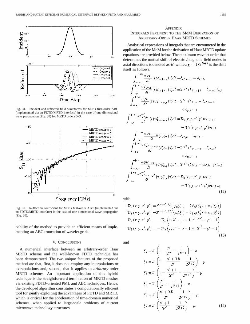
Results from a one-dimensional implementation of these con-cepts are shown in Figs. 31 and 32. A 0–5-GHz Gaussian pulsepropagation in a TEM waveguide mode is considered. Four HaarMRTD schemes of orders 0–3 with an effective cell size of0.0024 m and time step equal to 0.9 of their Courant limit areterminated into a Mur’s first-order ABC. The FDTD region oc-cupies two MRTD scaling cells for each scheme. Therefore, thethickness of the FDTD region for each case study is 0.0096,0.0192, 0.0384, and 0.0768 m, respectively. That is also thereason for the phase difference of the reflected waveforms inFig. 31. Finally, Fig. 32 presents the reflection coefficient ofeach of the four terminations. Obviously, the obtained ABC per-formance is similar in all MRTD cases and confirms the ca-
SARRIS AND KATEHI: EFFICIENT NUMERICAL INTERFACE BETWEEN FDTD AND HAAR MRTD 1155
Fig. 31. Incident and reflected field waveforms for Mur’s first-order ABC(implemented via an FDTD/MRTD interface) in the case of one-dimensionalwave propagation (Fig. 30) for MRTD orders 0–3.
Fig. 32. Reflection coefficient for Mur’s first-order ABC (implemented viaan FDTD/MRTD interface) in the case of one-dimensional wave propagation(Fig. 30).
pability of the method to provide an efficient means of imple-menting an ABC truncation of wavelet grids.
V. CONCLUSIONS
A numerical interface between an arbitrary-order HaarMRTD scheme and the well-known FDTD technique hasbeen demonstrated. The two unique features of the proposedmethod are that, first, it does not employ any interpolations orextrapolations and, second, that it applies toarbitrary-orderMRTD schemes. An important application of this hybridtechnique is the straightforward termination of MRTD meshesvia existing FDTD-oriented PML and ABC techniques. Hence,the developed algorithm constitutes a computationally efficienttool for jointly exploiting the advantages of FDTD and MRTD,which is critical for the acceleration of time-domain numericalschemes, when applied to large-scale problems of currentmicrowave technology structures.
APPENDIX
INTEGRALS PERTINENT TO THE MoM DERIVATION OF
ARBITRARY-ORDER HAAR MRTD SCHEMES
Analytical expressions of integrals that are encountered in theapplication of the MoM for the derivation of Haar MRTD updateequations are provided below. The maximum wavelet order thatdetermines the mutual shift of electric-/magnetic-field nodes inaxial directions is denoted as, while is the shiftitself as follows:
(12)
with
(13)
and
(14)

1156 IEEE TRANSACTIONS ON MICROWAVE THEORY AND TECHNIQUES, VOL. 51, NO. 4, APRIL 2003
Finally, is the well-known Kronecker delta and is theHaar mother wavelet function. The previous expressions arereadily programmabe and allow for the development of arbi-trary-order Haar wavelet MRTD codes. Yet code efficiency isgreatly enhanced bya priori recognizing thenonzerocoeffi-cients , , , and and omitting operations that involvemultiplications by zero in the main time-stepping loop. This isdone at the preprocessing stage of an MRTD code.
ACKNOWLEDGMENT
Author C. D. Sarris acknowledges an illuminating communi-cation with Prof. W. J. R. Hoefer, University of Victoria, Vic-toria, BC, Canada, and Dr. M. Fujii, University of Victoria, onthe motivation and performance of their TLM/Haar MRTD nu-merical interface.
REFERENCES
[1] R. Lotz and F. Arndt, “Advanced subgrid FD technique for modelingwaveguide structures with curved conducting and dielectric bound-aries,” in Proc. 30th Eur. Microwave Conf., Paris, France, Oct. 2000,pp. 288–291.
[2] I. S. Kim and W. J. R. Hoefer, “A local mesh refinement algorithm for thetime domain finite difference method using Maxwell’s Curl equations,”IEEE Trans. Microwave Theory Tech., vol. 38, pp. 812–815, June 1990.
[3] M. Okoniewski, E. Okoniewska, and M. Stuchly, “Three-dimensionalsubgridding algorithm for FDTD,”IEEE Trans. Antennas Propagat.,vol. 45, pp. 422–429, Mar. 1997.
[4] J. Ritter and F. Arndt, “A generalized 3D subgrid technique for theFDTD method,” inIEEE MTT-S Int. Microwave Symp. Dig., 1997, pp.1563–1566.
[5] M. Krumpholz and L. P. B. Katehi, “MRTD: New time domain schemesbased on multiresolution analysis,”IEEE Trans. Microwave TheoryTech., vol. 44, pp. 555–561, Apr. 1996.
[6] E. Tentzeris, R. Robertson, A. Cangellaris, and L. P. B. Katehi, “Space-and time- adaptive gridding using MRTD,” inIEEE MTT-S Int. Mi-crowave Symp. Dig., 1997, pp. 337–340.
[7] C. D. Sarris and L. P. B. Katehi, “On the use of wavelets for the imple-mentation of high order mesh refinement in time domain simulations,”in Proc. 30th Eur. Microwave Conf., vol. 3, 2000, pp. 284–287.
[8] , “Development and application of an efficient FDTD/MRTD nu-merical interface,” inIEEE MTT-S Int. Microwave Symp. Dig., vol. 2,2001, pp. 753–756.
[9] Z. Huang, K. Demarest, and R. G. Plumb, “An FDTD/MOM hybridtechnique for modeling complex antennas in the presence of hetero-geneous grounds,”IEEE Trans. Geosci. Remote Sensing, vol. 37, pp.2692–2698, Nov. 1999.
[10] T. I. Kosmanis, N. V. Kantartzis, and T. D. Tsiboukis, “A hybrid FDTD-wavelet-Galerkin technique for the numerical analysis of field singular-ities inside waveguides,”IEEE Trans. Magn., vol. 36, pp. 902–906, July2000.
[11] M. Fujii, P. P. M. So, E. Hu, W. Liu, and W. J. R. Hoefer, “A 2D TLM andHaar MRTD real time hybrid connection algorithm,” inProc. 16th Annu.Rev. Progress Applied Computer Electromagnetics, Monterey, CA, Mar.2000, pp. 1013–1020.
[12] S. Ju, D.-H. Bae, and H. Kim, “The modeling of lumped elements usingthe Haar wavelet multiresolution time domain technique,” inProc. URSIMeeting, Salt Lake City, UT, 2000.
[13] M. Fujii and W. J. R. Hoefer, “A three-dimensional Haar wavelet-basedmulti-resolution analysis similar to the 3-D FDTD method—Derivationand application,”IEEE Trans. Microwave Theory Tech., vol. 46, pp.2463–2475, Dec. 1998.
[14] C. D. Sarris and L. P. B. Katehi, “Fundamental gridding related disper-sion effects in MRTD schemes,”IEEE Trans. Microwave Theory Tech.,vol. 49, pp. 2248–2257, Dec. 2001.
[15] A. Taflove,Computational Electrodynamics: The Finite Difference TimeDomain Method. Norwood, MA: Artech House, 1995.
[16] I. Daubechies,Ten Lectures on Wavelets. Philadelphia, PA: SIAM,1992.
[17] E. M. Tentzeris, A. Cangellaris, L. P. B. Katehi, and J. F. Harvey, “Mul-tiresolution time-domain (MRTD) adaptive schemes using arbitrary res-olutions of wavelets,”IEEE Trans. Microwave Theory Tech., vol. 50, pp.501–516, Feb. 2002.
[18] K. Goverdhanam, C. D. Sarris, M. M. Tentzeris, and L. P. B. Katehi, “Aperfectly matched layer formulation for Haar wavelet based MRTD,” inProc. 29th Eur. Microwave Conf., vol. 3, 1999, pp. 243–246.
[19] S. Gedney, “The perfectly matched layer absorbing medium,” inAd-vances in Computational Electrodynamics: The Finite Difference TimeDomain Method, A. Taflove, Ed. Norwood, MA: Artech House, 1998,ch. 5.
[20] G. Mur, “Absorbing boundary conditions for the finite-difference ap-proximation of the time-domain electromagnetic field equations,”IEEETrans. Electromagn. Comput., vol. EMC-23, pp. 377–382, 1981.
Costas D. Sarris(M’03) received the Diploma (withdistinction) in electrical and computer engineeringfrom the National Technical University of Athens(NTUA), Athens, Greece in 1997, and the M.Sc.degree in electrical engineering, M.Sc. degree inapplied mathematics, and Ph.D. degree in electricalengineering from the University of Michigan at AnnArbor, in 1998, 2002, and 2002, respectively.
In November 2002, he joined the Edward S.Rogers Sr. Department of Electrical and ComputerEngineering, University of Toronto, Toronto, ON,
Canada, where he is currently an Assistant Professor.Dr. Sarris was the recipient of four Hellenic Fellowship Foundation Prizes
for the academic years 1993–1997, three Technical Chamber of Greece Awardsfor the academic years 1994–1997 (all of them for scholastic achievement), andthe 1997 NTUA/ECE Class Bronze Medal. He was also the recipient of a Stu-dent Paper Award (honorable mention) presented at the 2001 IEEE MicrowaveTheory and Techniques Society (IEEE MTT-S) International Microwave Sym-posium, Phoenix, AZ.
Linda P. B. Katehi (S’81–M’84–SM’89–F’95) re-ceived the B.S.E.E. degree from the National Tech-nical University of Athens, Athens, Greece, in 1977,and the M.S.E.E. and Ph.D. degrees from the Univer-sity of California at Los Angeles, in 1981 and 1984,respectively.
In September 1984, she joined the faculty ofthe Electrical Engineering and Computer ScienceDepartment, The University of Michigan at AnnArbor, as an Assistant Professor, and then becamean Associate Professor in 1989 and Professor in
1994. She has served in many administrative positions, including Director ofGraduate Programs, College of Engineering (1995–1996), Elected Member ofthe College Executive Committee (1996–1998), Associate Dean For GraduateEducation (1998–1999), and Associate Dean for Academic Affairs (sinceSeptember 1999). She is currently the Dean of the Schools of Engineering,Purdue University, West Lafayette, IN. She has authored or coauthored 410papers published in refereed journals and symposia proceedings and she holdsfour U.S. patents. She has also generated 20 Ph.D. students.
Dr. Katehi is a member of the IEEE Antennas and Propagation Society(IEEE AP-S), the IEEE Microwave Theory and Techniques Society (IEEEMTT-S), Sigma Xi, Hybrid Microelectronics, and URSI Commission D. Shewas a member of the IEEE AP-S AdCom (1992–1995). She was an associateeditor for the IEEE TRANSACTIONS ONMICROWAVE THEORY AND TECHNIQUES
and the IEEE TRANSACTIONS ONANTENNAS AND PROPAGATION. She was therecipient of the 1984 IEEE AP-S W. P. King (Best Paper Award for a YoungEngineer), the 1985 IEEE AP-S S. A. Schelkunoff Award (Best Paper Award),the 1987 National Science Foundation Presidential Young Investigator Award,the 1987 URSI Booker Award, the 1994 Humboldt Research Award, the 1994University of Michigan Faculty Recognition Award, the 1996 IEEE MTT-SMicrowave Prize, the 1997 International Microelectronics and PackagingSociety (IMAPS) Best Paper Award, and the 2000 IEEE Third MillenniumMedal.