Embed Size (px)
Citation preview
An Efficient Metadata Index Structure for Flash File
Systems Jaegeuk Kim* Heeseung Jo† Hyotaek Shim‡
KAIST KAIST KAIST
Jin-Soo Kim§ Sungkyunkwan University
Seungryoul Maeng**
KAIST
CS/TR-2010-324
Jan 12, 2010
K A I S T Department of Computer Science
* [email protected] † [email protected] ‡ [email protected] § [email protected] ** [email protected]

IEICE TRANS. INF. & SYST., VOL.Exx–D, NO.xx XXXX 200x1
REVIEW PAPER
An Efficient Metadata Index Structure for Flash File
Systems∗
Jaegeuk KIM†a), Student Member, Heeseung JO†, Hyotaek SHIM†, Jin-Soo KIM††,and Seungryoul MAENG†, Nonmembers
SUMMARYOne way to use NAND flash memory as storage media is a flashfile system. In order to design a high-performance flash file sys-tem, designing an efficient index structure that constitutes thelocations of metadata including directories and files in flash mem-ory is important. For large-capacity storage, the index structuremust be stored in the flash memory to achieve low memory con-sumption, but this may aggravate system performance. In thispaper, we propose hybrid indexing scheme to reduce the recur-sive flash updates as well as inode embedding scheme to minimizeadditional flash writes. We implemented a prototype called Di-rect Flash File System (DFFS) in a Linux OS with kernel ver-sion 2.6.21 on an embedded device. Comprehensive evaluationresults using Postmark and Filebench show that DFFS has notonly comparable performance to JFFS2 and YAFFS2, but alsobetter performance than UBIFS while achieving a small memoryfootprint and instant mount time.key words: NAND Flash Memory, Flash File System, MetadataManagement
1. Introduction
Flash memory is the most popular storage mediumfor embedded systems, especially in small personalelectronic devices such as personal digital assistants(PDAs), Portable Media Players (PMPs), and MP3Ps.Furthermore the capacity of flash memory has increasedexponentially due to the increased demand. For exam-ple, PMP requires huge storage capacity to deal witha large number of multimedia files including still pic-tures, MP3 songs, games, and movies. Although flashmemory is still more expensive than magnetic disks, ithas distinctive advantages such as small and lightweightform factors, solid-state reliability, low power consump-tion, and non-volatility [1].
NAND flash memory has different characteristicsfrom the traditional, de factor storage media, magneticdisks [2]. For example, NAND flash memory does notallow in-place updates, i.e., the previous data cannot be
Manuscript received November xx, 2009.Manuscript revised November 27, 2002.Final manuscript received October 29, 2003.†The authors are with the Computer Science Depart-
ment, KAIST, Republic of Korea††The author is with the School of Information and Com-
munication Engineering, Sungkyunkwan University, Repub-lic of Korea
a)E-mail: [email protected]∗This paper extends the paper that was presented at
ISORC’2008.
Service, application, ...
Virtual File System (VFS)
Existing File System(e.g. Ext2, Ext3, FAT, NTFS)
Flash Translation Layer(e.g. JFTL, dFTL)
Flash File System(e.g. JFFS2, YAFFS2, UBIFS)
NAND Flash Memory
Garbage
CollectionAddress
Mapping
Garbage
Collection
Index
Management
Fig. 1 Two major approaches for NAND flash-based storages.
overwritten at the same location without being erasedfirst. Also, the erase unit, which we call the flash eraseblock (FEB), is relatively larger than the flash page thatis the unit of read and write operations. Because of suchdifferences, NAND flash memory cannot be applied inexisting disk-based file systems directly.
To overcome these limitations, two major ap-proaches have been proposed, as illustrated in Fig. 1.One approach is to provide Flash Translation Layer(FTL) between the existing file systems and flash mem-ory [3–6]. The main purpose of FTL is to emulate thefunctionality of a block device with flash memory byhiding the erase-before-write characteristic as much aspossible. Once FTL is available on top of the flashmemory, any disk-based file system can be used. How-ever, since FTL is operating at the block device level,it is inaccessible to file system-level information such asthe liveness of data [7,8], and this may limit the storageperformance.
The other approach is to use flash file systemsspecially designed for flash memory. Over the pastfew years, several flash file systems have been devel-oped [8–13].
One of the most important issues in developingflash file systems is to design an efficient index struc-ture that is used to locate the positions of files andtheir metadata. In early proposed flash file systemssuch as JFFS2 [9] and YAFFS2 [10], the entire indexstructures are managed in the main memory. In thelarge-capacity storage system, however, a large number

2IEICE TRANS. INF. & SYST., VOL.Exx–D, NO.xx XXXX 200x
Table 1 Two types of NAND flash memory
SLC type MLC type
Page Size (Bytes) 2048 4096
# of pages in an FEB 64 128
Spare Area Size (Bytes) 64 128
Read latency (µs) 77.8 165.6
Write latency (µs) 252.8 905.8
Erase latency (ms) 1.5 1.5
of files can be created, making them suffer from highmemory consumption. UBIFS [13], a recently devel-oped flash file system, solves this problem by fetchingonly the needed indices on demand from flash memory,but it aggravates system performance compared withthe in-memory approach. In this paper, accordingly,we aim to design an on-flash index structure that showsthe performance not only better than that of UBIFS,but also comparable to JFFS2 and YAFFS2.
The goal of this work is to design a scalable indexstructure which supports more than several gigabytesof storage space, while providing the performance notonly better than UBIFS but also comparable to JFFS2and YAFFS2. Specifically, we propose two novel meta-data management schems, hybrid indexing and inodeembedding, to reduce the number of indirect indicesthat cause recursive index updates. To evaluate theproposed schemes, we designed and implemented a pro-totype flash file system, called DFFS (Direct Flash FileSystem), on the NOKIA N810 flatform [14] runnningthe Linux kernel version 2.6.21. With Postmark andFilebench programs, we evaluated DFFS with threeflash file systems, JFFS2, YAFFS2, and UBIFS, whichare widely used in embedded systems. In the Post-mark results, DFFS shows about 3.5 times better per-formance than UBIFS, and the Filebench results con-firm that DFFS improves the performance by up to 25%over UBIFS.
The rest of this paper is organized as follows. Sec-tion 2 introduces the characteristics of NAND flashmemory and overviews the exsiting flash file systems.Section 3 describes the motivation of our work, andsection 4 presents the design and implementation ofDirect Flash File System (DFFS). Section 5 shows theefficiency of our directory structure with comprehen-sive evaluation results. Finally, we conclude our paperin section 6.
2. Background and Related work
2.1 Background
A NAND flash memory chip consists of a set of blockscalled FEBs, and each FEB (flash erase block) containsa number of pages. A page is a unit of read and writeoperations, and an FEB is a unit of erase operation.
Each page has spare area typically used for storing anerror correction code (ECC) and the bookkeeping in-formation.
Currently, there are two types of NAND flashmemory, SLC (Single-Level Cell) [15] and MLC (Multi-Level Cell) [16]. Table 1 describes the general specifi-cation of two NAND types. Note that the read/writelatency shown in Table 1 includes the data transfertime between host and NAND flash memory. A fewbytes (typically 12 ∼ 16 bytes) of the spare area are as-signed to ECC in SLC NAND chips. For MLC NANDchips, almost every spare area needs to be allocated toECC due to the high bit error rate (BER) of memorycells. In both types, the number of write/erase cycles islimited to 10,000∼1,000,000 times. This necessitates awear-leveling process which aims at distributing the in-coming writes evenly across the flash memory for longerlifetime.
Recently, OneNAND flash memory was introducedto support both code and storage regions in a singlechip [17]. This fusion memory consists of SLC flashmemory, buffer RAMs, ECC hardware, and other con-trol logics. All the data including the code are storedin the SLC flash memory, and the code area is typically1,024 bytes supporting eXecute-In-Place (XIP). In or-der to improve the performance of I/O operations, twopage-sized buffer RAMs are interleaved one another.Because of these characteristics, OneNAND is widelyused in embedded systems.
2.2 Existing Flash File Systems
2.2.1 JFFS2 (Journalling Flash File System, v2)
JFFS2 is a log-structured flash file system designed forsmall-scale embedded systems [9]. Originally, it was de-signed for NOR flash memory, and extended to NANDflash memory later.
In JFFS2, a node, which has a variable number ofpages, is written sequentially to a free FEB. Nodes aretypically categorized into three types: (1 ) INODE, (2 )DIRENT, and (3 ) CLEANMARKER. Each INODEnode contains the metadata of a directory or a file.A directory has one INODE node and/or several DI-RENT nodes that contain directory entries. A file hasalso one INODE node and/or additional INODE nodeseach of which contains a range of the file’s data. Whenan FEB is erased successfully, JFFS2 writes a CLEAN-MARKER node to the FEB for reusing it safely.
In the main memory, JFFS2 maintains a chainedlist for all the nodes including obsolete nodes. Each in-memory node consists of a physical address, a length,and pointers to the next in-memory nodes that belongto the same file. The memory footprint increases inproportion to the number of nodes, and this is a severeproblem in the large-capacity storage system. To buildthe index structure in the main memory, JFFS2 scans
KIM et al.: AN EFFICIENT METADATA INDEX STRUCTURE FOR FLASH FILE SYSTEMS3
Table 2 A Comparison of Flash File Systems
JFFS2 YAFFS2 UBIFS DFFS
Storage Capacity Small Small Large Large
Memory Footprint Large Large Small Small
Mount Time Long Short Short Short
In-memory Structure Chained list Directory-tree and Tnode Cache Cache
On-flash Structure — — B+-tree Hash-based Index Structure
the entire flash memory at the mount-time; this steptakes from several to tents of seconds depending on thenumber of nodes.
2.2.2 YAFFS2 (Yet Another Flash File System, v2)
YAFFS2 is another log-structured flash file system de-signed for NAND flash memory [10]. Similar to JFFS2,a chunk consisting of a page and its spare area is writ-ten sequentially to a free FEB in YAFFS2. The sparearea in each chunk contains (i) file ID that denotes thefile inode number, (ii) chunk ID that indicates the off-set of the file’s data, and (iii) sequence number that isincremented when a new FEB is allocated to find theup-to-date valid data after system reboot.
In the main memory, YAFFS2 keeps the entire di-rectory tree comprised of a number of objects each ofwhich represents a directory or a file. An object holdsthe physical location of its chunk on flash memory, andpoints to the parent and the sibling objects. If the ob-ject is a directory, it also points to the child objects.If it is a file, a tree structure, called Tnode, is formedto provide the mapping from a file offset to the physi-cal address of its chunk on flash memory. In order tobuild these in-memory structures, YAFFS2 also suffersfrom the large memory consumption, as in JFFS2. Onthe other hand, to reduce the mount delay, YAFFS2adopts checkpoint that is a well-known technique forfast system boot by reading a small amount of check-point information.
2.2.3 UBIFS
UBIFS is designed for large-capacity storage byaddressing the memory consumption problem inJFFS2 [13]. The key feature is that UBIFS organizesthe index structure on flash memory, whereas JFFS2maintains it in the main memory.
On flash memory, UBIFS adopts the node struc-ture in JFFS2, and uses a B+-tree to manage the nodeindices. For the B+-tree, two node types, MASTERand INDEX, are introduced in addition to other nodetypes (INODE, DIRENT, and CLEANMARKER) inJFFS2. The MASTER node points to the root of thetree, and the leaves of the tree contain valid data. Theinternal elements of the tree are INDEX nodes thatcontain only pointers to their children.
When a leaf node is added or replaced, all thenodes from the parent INDEX node to MASTER nodemust be also replaced. If all the ancestor INDEX nodesare updated every time a new leaf node is written, it isvery inefficient since almost the same INDEX nodes arewritten repeatedly. To reduce the frequency of updates,therefore, UBIFS defines a journal. UBIFS writes apredefined number of leaf nodes to the journal first,instead of immediately inserting them to the B+tree.When the journal is considered full, the leaf nodes inthe journal are committed to the B+-tree.
In the main memory, UBIFS adopts tree nodecache (TNC) to make tree operations more efficient bycaching some INDEX nodes. To reduce the mount de-lay, UBIFS also adopts checkpoint, similar to YAFFS2.
3. Motivation
As summarized in Table 2, JFFS2 and YAFFS2 con-sume a lot of memory to retain the complete directorystructure in memory. If there is not enough memory,the mount even fails. To reduce the memory footprint,UBIFS fetches only the needed indices on demand fromflash memory, as is done in most disk-based file sys-tems. The fetched indices are cached in the main mem-ory for a while to accelerate the subsequent accessesto the same indices, and they are eventually discardedlater under memory pressure. This on-demand scheme,however, results in long latency for storing and retriev-ing indices during file system operations, and accord-ingly, it is essential to make an efficient on-flash indexstructure that minimize performance degradation dur-ing metadata operations.
To design an efficient on-flash index structure, thispaper investigates two novel metadata managementschemes. First, we speed up the directory lookup oper-ation by storing the directory inode and its associateddirectory entries in one page. The traditional directorylookup operation repeats the following three steps un-til it reaches the end of pathname: (1) read the inodeof the current directory, (2) read the contents (direc-tory entries) of the current directory, and (3) search forthe target child name in directory entries and obtainthe corresponding inode number. In most file systems,inodes are kept separately from its data. Therefore,two flash read operations, one for the directory inodeand the other for its contents, are needed whenever a
4IEICE TRANS. INF. & SYST., VOL.Exx–D, NO.xx XXXX 200x
Indirect pointer
Check
pointDirInode_Map DirInode
Virtual
DirInodeFileInode
“/” “file1”Array [0]
data 0
NAND Flash Memory
Direct pointer
Directory Structure File Structure : Append Only
Hybrid Inode Index Structure
data 1
Inode for “/” Inode for “dir” Inode for “file1”
Bucket [0]
Bucket [1]
...
…… [346]
“dir”Bucket [0]
Bucket [1]
...
…… [346]
Root inode
“file2”
Inode for “file2”
“dir”Bucket [0]
Bucket [1]
...
…… [346]
Virtual DirInode for “dir”x
...
x
Array [1]
Array [2]
Array [3]
...
...
...
...
Array [511]
A flash page
dir
file2
file1/
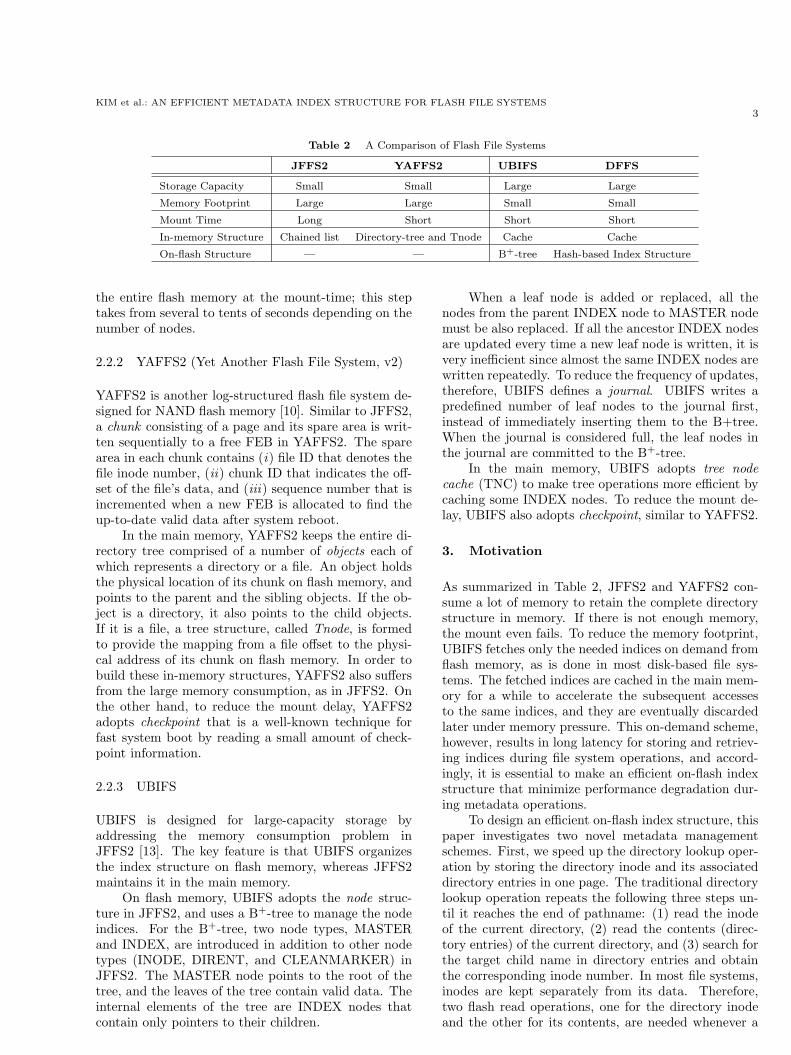
Fig. 2 Overall architecture of DFFS.
directory lookup operation is performed. Instead, weembed directory entries with the directory inode in thesame page so that the directory lookup operation canbe carried out by just one flash read operation. Thisis feasible as the current NAND flash memory has arather large page size ranging from 2KB to 8KB.
The other scheme we consider is the hybrid inodeindexing structure. In disk-based file systems, the in-ode of a file can be freely updated whenever there is achange in the file. In flash memory, however, the up-dated inode cannot be written into the previous loca-tion due to the erase-before-write characteristics; hence,inodes will float over the flash memory area and the filesystem should be able to locate a file’s latest version ofinode. JFFS2 and YAFFS2 keep such information inmemory and that is why they require so much mem-ory. On the other hand, UBIFS manages a large B+-tree for all the locations. The log-structured file system(LFS) [18] solves this problem by introducing an inodemap, which is basically a mapping table from the inodenumber to the current copy of the inode. Our hybridinode indexing scheme is similar to LFS except thatthe physical location of a regular file’s inode is directlyspecified in the corresponding directory entry. Notethat the directory inodes are still accessible throughthe mapping table. This scheme reduces the size of themapping table significantly, since regular files outnum-ber directories in most cases.
4. Direct Flash File System (DFFS)
4.1 Overall Structure
Fig. 2 shows the overall architecture of the proposedfile system, DFFS (Direct Flash File System). DFFSmaintains six major log areas in the flash memory log-ically, and each log area consists of several FEBs thatare allocated on demand. In the (1 ) checkpoint area,
DFFS stores basic file system information, Root inodeposition, and locations of DirInode Maps and other logareas. (2 ) DirInode Map is used to translate an direc-tory inode number to its physical address in the flashmemory, and details are introduced in section 4.2.
In DFFS, an inode occupies one flash page withmetadata such as its file name, inode number, file size,atime, dtime, and so on. This is possible since the pagesize of NAND flash memory is relatively larger thanthe amount of metadata [8]. In the directory structure,each inode page containing directory entries for thechild files is written to the (3 ) DirInode area. Throughthis embedding scheme, the directory lookup operationcan be completed by reading one flash memory page.Likewise, when a file is created or deleted, this schemerequires only one flash write operation by updating theparent inode and its directory entries together.
This directory structure can be implemented us-ing either a balanced tree or a hash table. Althoughthe B+-tree structure used in UBIFS works reasonablywell under circumstances that numerous files are cre-ated and deleted dynamically [19], it may show extraupdate cost in flash memory caused by maintainingindirect indexing pages during split and merge oper-ations. For simplicity, DFFS adopts a hash table thatperforms the average lookup operation in O(1) and haslow update cost.
To use the hash table efficiently, hash collisionsshould be handled carefully. When a hash collisionoccurs, DFFS allocates another (4 ) Virtual DirInodeholding hash buckets and makes a doubly linked listwith the original DirInode. In DFFS, hash collisionsoccur in proportion to the number of files in a direc-tory. Section 4.3 and 4.4 describes the proposed direc-tory structure more in details.
For the file structure, DFFS has two log areas, (5 )FileInode and (6 ) Data, respectively. In DFFS as a pro-totype, a FileInode contains data entries having phys-

KIM et al.: AN EFFICIENT METADATA INDEX STRUCTURE FOR FLASH FILE SYSTEMS5
D
D
Directory File
D
D
F
D F F 1. File is updated
2. Parent is updatedD
D 4. Root is updated
F D 3. Grandparent is updatedD
Newly written page
Fig. 3 Wandering tree problem.
ical pointers of file’s data. Note that DFFS does notsupport data updates, because this paper is focused onthe directory structure.
4.2 Inode Indexing Structure
There are two inode indexing schemes used in flash filesystems. One is a logical (indirect) indexing schemewhich refers to a mapping table entry to acquire thephysical location of an inode. The other is a physical(direct) indexing scheme which indicates the page loca-tion of an inode directly. Although the logical indexingscheme includes mapping table access overhead, it caneasily update the physical location of an inode with-out affecting the parent directory entry. On the otherhand, while the physical indexing scheme has low accesslatency, the parent directory entry should be also up-dated whenever the location of the child inode changes.As illustrated in Fig. 3, this necessitates another updatein the grandparent directory and, eventually, updatesare propagated to the root directory. Such recursiveindex updates caused by out-of-place update is calleda wandering tree problem [20].
DFFS introduces hybrid indexing scheme to mit-igate the wandering tree problem, to reduce the map-ping table size, and to enhance the file access latency.DFFS has three indexing pointers: (1 ) directory-to-directory, (2 ) directory-to-file, and (3 ) hash-collisionpointers (e.g. a pointer between the DirInode and theVirtual DirInode for “dir”), as illustrated in Fig. 2.
By consideration of frequent inode updates, DFFSadopts the logical indexing scheme between directorypointers. For the directory-to-file pointers, DFFS takesthe physical indexing scheme by substituting the inodenumber in the directory entry with the physical locationof the inode. This makes it possible not only to accessall the children directly, but to reduce the size of themapping table required for the logical indexing scheme.In addition, the file system does not have to managefree inode numbers and inode locations for regular files.Finally, DFFS simply uses the logical indexing schemefor hash-collision pointers as the hash collision will berare.
The mapping table called DirInode Map for logicalpointers is organized in a linear array and the total size
NAND Flash Memory
Attributes
File Name
Pre vDirInode
Hash Table
DirInode
Virtual DirInodes
FileInode
FileInode
DirInode
DirInode
SeparatesDirInode and FileInode
Flash pages
Flash pages
Translated byDirInode_Map
Next vDirInode
Flash page
23457
3
Metadata
Hash Table
23451
Flash page
Metadata
Hash Table
234564
Fig. 4 Directory structure; dotted and solid lines indicate in-direct and direct pointers, respectively.
is designed not to exceed over the size of one FEB. ForSLC NAND flash memory, the size of an FEB is 128KBthat can provide up to 32K entries. Since the numberof directories in default Linux installation is less than20K, we believe the size of one FEB is enough in anembedded environment.
4.3 Directory Structure
As illustrated in Fig. 4, DirInode consists of (i) at-tributes (44 bytes) that contains the basic informationof the child file or directory, such as atime, dtime, uid,gid, parent inode pointer, and so on, (ii) a file name(256 bytes) that represents the name of the file or di-rectory, (iii) a pointer (4 bytes) to the previous VirtualDirInode, (iv) a pointer (4 bytes) to the next VirtualDirInode, and (v) a set of 4-byte buckets for a hash ta-ble whose size is determined by the size of a page suchas 2KB and 4KB. For example, when the size of a pageis 2KB, the hash table can contain 347 buckets, andin a 4KB page, it can cover about 750 directory entrybuckets. Note that the structure of Virtual DirInode issame as that of DirInode.
For an example illustrated in Fig. 2, when lookingup “/dir/file2”, DFFS performs following procedures.(1 ) It obtains the Root inode by reading a page indi-cated by the pointer in the checkpoint data. (2 ) Inthe Root inode page, it obtains 3, the indirect pointer,from the bucket [0] indicated by the hashed numberof “dir”; the hashed number is 0 in this case. (3 ) Ittranslates the indirect pointer to a physical location(Array[3]) through the DirInode Map. (4 ) By read-ing a page written to the location, DFFS obtains theDirInode named “dir”. (5 ) In the DirInode, it finds thebucket [1] hashed by “file2”, and loads a page indicatedby the bucket. Unfortunately, this inode page is colliedone occupied by “file1” so that DFFS reads the nextVirtual DirInode page. (6 ) By reading a page indicatedby the bucket [1] in the Virtual DirInode, a FileInodenamed “file2” is sucessfully obtained. Further access todata of the “file2” can be performed with direct data

6IEICE TRANS. INF. & SYST., VOL.Exx–D, NO.xx XXXX 200x
H = Hash(“File Name”)
P = pDirInode[H]
Next vDirInode
Is Exist?
Yes
Yes
Fill the Inode
with the Page
No
Open a File or Directory
· pDirInode[H] : H’th bucket in the parent DirInode
· Next vDirInode : Next Virtual DirInode
Target Name
Is Matched?
No
P = Next vDirInode[H]
Read_Page(P)
Fail to Open
Fig. 5 Open Operation Flow.
pointers in the FileInode.
4.4 Directory Operations
4.4.1 Open Operation
During the open operation, the pathname resolution ishandled by the VFS (Virtual File System) layer. Allthe thing that DFFS needs to do is to return the inodethat matches the pathname component in the parentdirectory.
As shown in Fig. 5, DFFS first reads the hash ta-ble embedded in the parent inode. To locate the childinode, DFFS obtains its hash value, H, and then, itfinds the pointer that is assigned by the hybrid index-ing scheme. This pointer is translated to the physicallocation on the flash memory determined by
Flash Position ={
P− L if (P > L)DirInode Map[P] otherwise
where L is the maximum number of logical pointers thatcan be assigned†.
If there is no hash collision, DFFS can find thechild inode by reading one page. Otherwise, it followseach of the next Virtual DirInode. To avoid visiting allthe collided children inside virtual inodes, DFFS usesan extra small hash table in a directory inode whichoccupies one byte per a bucket. Consequently, DFFSmakes use of two hash tables in each directory inodefor better open operation performance.
4.4.2 Create Operation
As shown in Fig. 6, the create operation can be classi-†In DFFS, L is 65536 in default.
P = New
Indirect PointerTarget File Type Directory
P = New
Direct Pointer File
H = Hash(“File Name”)
pDirInode[H] pDirInode[H] = P
Next vDirInode
Is Exist?
Empty
Occupied
Allocate New
Next vDirInode No
Next vDirInode[H] = PNext vDirInode[H]
YesOccupied
Empty
End
Create a File or Directory
· pDirInode[H] : H’th bucket in the parent DirInode
· Next vDirInode : Next Virtual DirInode
Fig. 6 Create Operation Flow.
fied into two cases: one for a regular file and the otherfor a directory file. In the former case, DFFS allocatesone physical index and then inserts (the physical index+ L) to the corresponding bucket in the parent DirIn-ode. In the latter case, DFFS inserts the logical indexto the bucket, and the newly allocated page index isinserted to the DirInode Map[logical index].
If a hash collision occurs during this process, theempty bucket in one of the next Virtual DirInodes isused. If there is no Virtual DirInode, a new one isallocated and linked with the last Virtual DirInode byupdating its Next vDirInode pointer. As a consequence,the new and the last Virtual DirInodes are linked to-gether.
4.4.3 Delete Operation
As shown in Fig. 7, when a file or a directory is deleted,DFFS has the target inode with its pointer so that ittries to search for a bucket that is matched to it. Ifthe matched bucket is in the parent DirInode, DFFSsimply invalidates the bucket. Otherwise, DFFS findsa Virtual DirInode that has the matched bucket and in-validates it. If the Virtual DirInode becomes empty, itspage is invalidated, and both previous and next VirtualDirInodes are updated.
4.5 Garbage Collection
To support garbage collection, DFFS basically allo-cates separated blocks for each data structure. In otherwords, there are three logical sections that are calledmetadata, data, and superblock. In this paper, DFFS

KIM et al.: AN EFFICIENT METADATA INDEX STRUCTURE FOR FLASH FILE SYSTEMS7
pDirInode[H] =
Empty
Next vDirInode
Is Exist?
No
No
Yes
Fail to delete
Delete a File or
Directory
· pDirInode[H] : H’th bucket in the parent DirInode
· Pre vDirInode : Previous Virtual DirInode
· Next vDirInode : Next Virtual DirInode
H = Hash(“File Name”)
P = pDirInode[H]
Target PIs Matched?
P = Next vDirInode[H]
Invalidates the
target Inode pageYes
Success
Next vDirInode
Is Empty?
Target PIs Matched?
Next vDirInode[H] =
EmptyYes
Yes
Invalidates the Next
vDirInode page
Update Pre vDirInode
& Next vDirInode
No
No
Fig. 7 Delete Operation Flow.
uses metadata and superblock partitions. The wholeinformation related to directory structures resides onthe metadata partition. During the garbage collectionprocess, DFFS selects a victim metadata block usinga heuristic (for instance, the block with the smallestvalid-copies). When a victim block is selected, DFFSchecks all the inodes in the block whether it is validor not by verifying mutual pointers between child andparent inodes. Note that, in DFFS, child and parentinodes always point to each other as long as both arevalid. After checking validity, it copies the valid pageto the last log position according to the inode type. Inthis paper, DFFS is designed to support garbage col-lection mechanism with low cost and to give a chanceto adopt various garbage collection algorithms.
5. Performance Evaluation
5.1 Evaluation Environment
In this section, we evaluate the performance of DFFS.We implemented DFFS on the Linux kernel version2.6.21, and used NOKIA N810 for the experimentalplatform. The Nokia N810 is an Internet tablet appli-ance, which allows the user to browse the Internet andcommunicate using Wi-Fi networks or with a mobilephone via Bluetooth [14]. In addition to the Internetactivities, the N810 supports abundant multimedia ser-vices such as movie players, MP3 players, and camerafunctionalities. It is composed of an embedded Linuxsystem with a 400Mhz processor, 128MB DDR RAM,and a 256MB OneNAND chip. The system parametersfor our experiments are summarized in Table 3.
Since the general architecture of DFFS is based on
Table 3 System Environment for Experiments
System Specification OneNAND
Platform: Nokia N810 Part Number: KFG4G16Q2M
CPU: TI OMAP 2420 Block Size: 128KB
Memory: DDR 128MB Page Size: (2048 + 64) Bytes
Flash Memory : OneNAND Read Bandwidth: 108MB/s
OS: Linux 2.6.21 Write Bandwidth: 9.3MB/s
MTD: onenand.c Erase Bandwidth: 64MB/s
the log-structured file system [18, 21], DFFS allocatesa physical page from the last log pointer whenever itneeds a free page for new metadata. The popular SHA-1 algorithm is used as a hash function which generatesa pseudo-random number from the given string [22].
We compared DFFS with JFFS2, YAFFS2, andUBIFS. For fair comparisons, we erased all the FEBsbefore initiating each experiment for UBIFS to avoidwear-leveling processes. In addition, we set no compres-sion mode for file data in JFFS2 and UBIFS. Since theOneNAND driver is not fully compatible with YAFFS2,we set in-band tags as a mount option that makesYAFFS2 operate without the use of spare areas.
Under this environment, we used two benchmarkprograms: Postmark [23] and Filebench [24]. For com-parison purposes, we tried to normalize the throughputof all the tested file systems as much as possible, andthe absolute value was written over a standard bar ofthe benchmark results.
Postmark is one of the most popular benchmarks,which performs intensive Internet electronic mail serveroperations. It measures the overall transaction rate inoperations/sec (ops/s) while creating and deleting nu-merous files in a number of subdirectories.
Filebench is a framework emulating file systemworkloads for evaluating system performance quicklyand easily with various script files. In this bench-mark, we made three workloads: Create, Copy, andCreate/Delete. The Create and Copy workloadsare micro benchmarks for evaluating the basic perfor-mance of creating and copying many files, and the Cre-ate/Delete workload is a macro benchmark basedon a modified file server script for the user environment.Unlike the Postmark benchmark, the structure of a di-rectory tree and the size of file data are determined bymeans of a gamma distribution.
5.2 Resource Consumption
First of all, we examine the amount of memory requiredfor JFFS2, YAFFS2, UBIFS, and DFFS. Fig. 8(a) com-pares the total memory consumption after each file sys-tem is mounted. It is clear that JFFS2 and YAFFS2show large memory consumption in proportional tothe number of total files. Although UBIFS needsmuch larger memory for several FEB-sized buffers than

8IEICE TRANS. INF. & SYST., VOL.Exx–D, NO.xx XXXX 200x
0
50
100
150
200
250
300
350
400
450
500
500 1000 1500 2000
Me
mo
ry U
sage
(K
B)
JFFS2 YAFFS2 UBIFS DFFS
(a) Memory consumption according to the number of totalfiles.
0
1
2
3
4
5
6
7
8
9
500 1000 1500 2000
Mo
un
t La
ten
cy (
s)
JFFS2
YAFFS2
UBIFS
DFFS
(b) Mount latency according to the number of total files.
Fig. 8 Resource consumption of DFFS.
YAFFS2 and JFFS2, 400 KB seems to be enough allthe time. Instead, DFFS shows a considerably smallmemory footprint independent of the number of files.This is because DFFS reads only the minimal infor-mation during the mount time, such as super block,checkpoint block, and the root inode.
Fig. 8(b) displays the mount latency. Since JFFS2and YAFFS2 scan the whole flash memory medium tobuild the directory structure, it takes up to several sec-onds to mount a file system. The mount latency is alsoproportional to the number of files. On the contrary,we can notice that UBIFS and DFFS can be mountedinstantly.
5.3 Postmark Benchmark
This test consists of three phases. In our experiment,Postmark initially builds 100 subdirectories in the rootdirectory. In the first create phase, Postmark creates1300 files with 128KB of data in a randomly chosensubdirectory. In the second mixed phase, 2000 mixedoperations that consist of create and delete operationsare performed randomly; each create operation includes128KB of data writes. Finally, in the delete phase,all the remaining files are deleted.
To measure the index structure overhead inten-sively, we set the O SYNC flag to all open files, whichenables that a file system writes an inode whenever anew data is written. As shown in Fig. 9, YAFFS2 showsbetter performance than JFFS2, since it writes smaller-sized node headers during data writes. UBIFS showsworst performance among them, because it fetchesmetadata on demand from the flash memory. DFFSalso adopts this, but it could reduce the index man-agement overhead and the garbage collection cost si-multaneously. In particular, DFFS could reduce thegarbage collection cost significantly, because DirInodesand FileInodes are stored in different log areas, which
Table 4 Configurations of Filebench
# of Files Directory
Width
File Size I/O Size
Create 1000 100 128KB 4KB
Copy 500 20 128KB 4KB
Create/Delete 2000 20 128KB 64KB
enables the hot and cold data separation [25]. The dif-ference of the elapsed time for writing data betweenUBIFS and DFFS is caused by writing node headers inUBIFS.
5.4 Filebench Benchmark
Table 4 summarizes the configurations of each test, andFig. 10 shows the bandwidth results and a breakdownof the elapsed time during the Create/Delete test.These results are normalized to the results of UBIFSthat is our target file system. In the Create/Deletetest, the performance is measured by carrying out thetest during the total 1000 seconds. Note that the break-down policy to show the time overhead is slightly differ-ent from the Postmark result, since the total time is setto finish the Filebench test, whereas the total numberof transactions is used in the Postmark test.
Unlikely the Postmark result, UBIFS shows betterperformance than JFFS2 in the micro tests. Becausethis test set dsync to the files instead of O SYNC, whichenables that only data is synchronized. As a result,UBIFS could perform less number of metadata oper-ations, and this reduces the garbage collection over-head together. In the macro test, UBIFS and DFFSshow better performance than JFFS2 and YAFFS2 aswell for the same reason. YAFFS2 shows worst perfor-mance with large garbage collection overhead, becausethis test uses much larger workload than the Postmarktest does.

KIM et al.: AN EFFICIENT METADATA INDEX STRUCTURE FOR FLASH FILE SYSTEMS9
0
0.5
1
1.5
2
2.5
3
3.5
4
4.5
YAFFS2 JFFS2 UBIFS DFFS
No
rma
lized
Tra
ns
ac
tio
n R
ate
(o
ps
/s)
5.59
(a) Normalized transaction rate.
0
50
100
150
200
250
300
350
400
YAFFS2 JFFS2 UBIFS DFFS
Ela
pesed
Tim
e (
secs)
Writing Data
Managing indices
Garbage Collection
(b) Elapsed time breakdown.
Fig. 9 Postmark Results (ops/s).
0
0.2
0.4
0.6
0.8
1
1.2
1.4
CreateFiles CopyFiles Create/DeleteFiles
Micro Macro
No
rma
lize
d B
an
dw
idth
(M
B/s
) YAFFS2 JFFS2 UBIFS DFFS
2.4 3.5 2
(a) Normailzed bandwidth.
0
100
200
300
400
500
600
700
800
900
1000
YAFFS2 JFFS2 UBIFS DFFS
Ela
pesed
Tim
e (
secs)
Writing Data
Managing indices
Garbage Collection
(b) Elapsed time breakdown in the Create/Delete test.
Fig. 10 Filebench Results.
6. Conclusions
In this paper, we propose a novel metadata man-agement schemes, hybrid indexing and inode embed-ding schemes for flash file systems. We implementeda prototype called Direct Flash File System (DFFS)on a NOKIA N810 platform, and evaluated DFFSwith YAFFS2, JFFS2, and UBIFS, which are widelyused in various embedded systems. From the results,when many metadata operations are triggered by theO SYNC flag, UBIFS and DFFS which adopt the on-demand index fetching scheme can show worse per-formance than YAFFS2 and JFFS2. However, DFFScould reduce the performance degradation as much aspossible by the proposed schemes. On the other hand,if a few metadata operations are triggered, UBIFS andDFFS are competitive sufficiently by reducing the in-dex management and garbage collection costs. Fromthe Postmark results, DFFS shows about 3.5 times bet-
ter performance than UBIFS, and the Filebench resultsconfirm that DFFS improves the performance by up to25% over UBIFS.
References
[1] F. Douglis, R. Caceres, M. Kaashoek, K. Li, B. Marsh, andJ. Tauber, “Storage Alternatives for Mobile Computers,”Symposium on Operating Systems Design and Implemen-tation (OSDI), pp.25–37, 1994.
[2] C. Glavin and R. Kugele, “Nand vs. hard disk drives: Hype,myth and reality,” the report of Needham & Company,2005.
[3] A. Kawaguchi, S. Nishioka, and H. Motoda, “A Flash-Memory Based File System,” USENIX Winter Conference,pp.155–164, 1995.
[4] J. Kim, J. Kim, S. Noh, S. Min, and Y. Cho, “A spaceefficient flash translation layer for CompactFlash systems,”IEEE Transactions on Consumer Electronics, vol.48, no.2,pp.366–375, 2002.
[5] J.U. Kang, H. Jo, J.S. Kim, and J. Lee, “A superblock-based flash translation layer for nand flash memory,” Pro-ceedings of the 6th ACM and IEEE International Con-

10IEICE TRANS. INF. & SYST., VOL.Exx–D, NO.xx XXXX 200x
ference on Embedded Software (EMSOFT06), pp.161–170,2006.
[6] H.J. Choi, S.H. Lim, and K.H. Park, “Jftl: A flash transla-tion layer based on a journal remapping for flash memory,”ACM Transactions on Storage, vol.4, no.4, 2009.
[7] M. Sivathanu, L.N. Bairavasundaram, A.C. Arpaci-Dusseau, and R.H. Arpaci-Dusseau, “Life or death at block-level,” Proceedings of the 6th Symposium on OperatingSystems Design and Implementation (OSDI’04), pp.379–394, 2004.
[8] S.H. Lim and K.H. Park, “An efficient nand flash file systemfor flash memory storage,” IEEE Transactions on Comput-ers, vol.55, no.7, pp.906–912, 2006.
[9] D. Woodhouse, “JFFS: the journalling flash file system,”Ottawa Linux Symposium, 2001.
[10] Aleph One Company, “Yet another flash file system(YAFFS),” @ http://www.aleph1.co.uk/yaffs.
[11] E. Gal and S. Toledo, “A Transactional Flash File Systemfor Microcontrollers,” USENIX Annual Technical Confer-ence, pp.89–104, 2005.
[12] C. Lee, S.H. Baek, and K.H. Park, “A hybrid flash file sys-tem based on nor and nand flash memories for embeddeddevices,” IEEE Transactions on Computers, vol.57, no.7,pp.1002–1008, 2008.
[13] A. Hunter, “A brief introduction to the design of ubifs,”http://www.linux-mtd.infradead.org, 2008.
[14] Nokia, N810 Internet Tablet, 2008.[15] Samsung Electronics, “2gx8 bit slc nand flash memory spec-
ification,” K9GAG08U1A, 2006.[16] Samsung Electronics, “2gx8 bit mlc nand flash memory
specification,” K9GAG08U0M-P, 2006.[17] Samsung Electronics, “4gx8 bit onenand flash memory
specification,” KFG4G16Q2M, 2006.[18] M. Rosenblum and J. Ousterhout, “The Design and Imple-
mentation of a Log-Structured File System,” ACM Transa-tions on Computer Systems, vol.10, no.1, pp.26–52, 1992.
[19] W. Litwin, “Linear Hashing: A New Tool for File and TableAddressing,” International Conference on Very Large DataBases (VLDB), pp.212–223, 1980.
[20] A. Bityutskiy, JFFS3 design issues.[21] M. Seltzer, K. Bostic, M. McKusick, and C. Staelin,
“An Implementation of a Log-Structured File System forUNIX,” USENIX Winter Conference, pp.307–326, 1993.
[22] FIPS 180-1, Secure Hash Standard, 1995.[23] J. Katcher, “Postmark: a new file system benchmark,” the
report of Network Appliance Tech TR3022, 1997.[24] R. McDougall, J. Crase, and S. Debnath, FileBench: File
System Microbenchmarks, 2006.[25] L.P. Chang, T.W. Kuo, and S.W. Lo, “Real-time garbage
collection for flash-memory storage systems of real-time em-bedded systems,” ACM Transactions on Embedded Com-puting Systems, vol.3, no.4, pp.837–863, 2004.


![[TR-e-IoT-SCS-Part-8] Metadata Certification Policy Beta v1.0 … · 2019-06-12 · [TR-e-IoT-SCS-Part-8] Metadata Certification v1.0 3 Date Version Description of changes 07/01/19](https://img.dokumen.tips/doc/110x75/5e883d2d3ccd3926ec470be3/tr-e-iot-scs-part-8-metadata-certification-policy-beta-v10-2019-06-12-tr-e-iot-scs-part-8.jpg)