Embed Size (px)
Citation preview

AN AUTOMATIC STRANGER REMOVAL PHOTOGRAPHY SYSTEM USING PANORAMIC
INPAINTING
1
An Automatic Stranger Removal Photography System
Using Panoramic Inpainting
*1W. G. C. W. KUMARA, *2TIMOTHY K. SHIH, AND #3SHIH-MING CHANG
*Department of Computer Science and Information Engineering, National Central University
No. 300, Jhongda Rd., Jhongli City, Taoyuan County 32001, Taiwan (R. O. C.) #Department of Computer Science and Information Engineering, Tamkang University
No. 151, Yingzhuan Rd., Tamsui Dist., New Taipei City 25137, Taiwan (R. O. C.)
E-mail: {1chinthakawk, 2timothykshih}@gmail.com, [email protected]
Moving human objects (or ‘strangers’ as referred here) in the background obscure the
scenery in regular panorama photography. Hence this paper proposes a novel method to
remove the strangers from the background of the panorama. In the proposed system the
object segmentation, dynamic background inpainting, and panorama creation phases are
used to compose a panorama. If the detected face data of the stranger are not in the face
database of the camera, the stranger is automatically removed from the panorama in the
background repair phase which is known as inpainting. Panorama creation of the developed
system is fully automatic. If a moving human object in the background that the user
intended to remove from the panorama is not automatically detected, the user can manually
select that stranger in the object segmentation phase. Then the manually selected stranger is
removed from the panorama in the background repair phase. Experimental results
demonstrate that the proposed system effectively removes strangers in the background and
generates the panorama. Complete results set can be accessed at
http://video.minelab.tw/PanoramaInpainting.
Keywords: Panorama, inpainting, automatic grabcut.
1. INTRODUCTION
Panorama photography has become popular within the general users, skilled
photographers, and computer and Internet based applications. With the introduction of
panorama photography support in the general purpose digital cameras and smart phones,
users and applications that use the panorama photos have also increased in numbers.
People take photographs of their preferred scenes every day either with standalone
cameras or the ones equipped in the mobile devices. It often requires to avoid the moving
human objects from the background while capturing, since such objects usually obscure
the structures and scenery in the background. These moving human objects in the
background is referred as strangers in the rest of the paper. If the strangers are still visible
in the photograph, tools like smoothing and fading, which are available in image editing
software are mostly used to remove such strangers. Due to the series of steps to be
followed and required expertise on the tool, most of the image or video editing software
are not suitable for a general user for daily requirements. On the other hand additional
background information of the scenery can be obtained with a panorama. Panorama
photography is mostly used to capture natural scenery or famous buildings which are

W. G. C. W. KUMARA, TIMOTHY K. SHIH, AND SHIH-MING CHANG 2
normally dense with strangers. These strangers in the scene result in foggy shades in the
panorama and obscure the background. Two example panoramas generated with the
Autostitch1 application [1], [2] with such noticeable artifacts are shown in Figure 1.
Figure 1. Selected example results obtained with the Autostitch where strangers in the
background appear as foggy shades in the panorama.
The main objective of this research was to develop a panorama generation system
eliminating foggy shades caused by the strangers, as a simple tool for a general user to
use in the daily life. To generate a panorama with the proposed system the user first
captures a short video focusing the main human character following a clockwise
trajectory starting from the center. Then the captured short video is fed in to the system to
extract several frames. Finally, the system generates the panorama without the strangers
in the background as illustrated in Figure 2.
Figure 2. The main phases of proposed method.
Two main contributions can be highlighted in this paper. First, a systematic
approach is presented to compose a panorama without strangers in the background using
inpainting techniques. Panorama generation technologies proposed so far are lack of user
input or any automatic method to adjust the result based on the user preferences. As an
example the user may want to compose the panorama with only the people she preferred
to have. Image inpainting technique has been used here addressing that gap. Second, an
integrated panorama generation system is implemented which improves and combines
several available image processing techniques like face detection, video inpainting,
feature point detection and matching etc.. This is a very suitable application that can be
introduced as a mobile application. Then the user have the freedom in capturing
panorama with the people she preferred to have.
1 http://www.cs.bath.ac.uk/brown/autostitch/autostitch.html

AN AUTOMATIC STRANGER REMOVAL PHOTOGRAPHY SYSTEM USING PANORAMIC
INPAINTING
3
The proposed system consists of three main phases namely, object segmentation,
dynamic background inpainting and panorama creation as shown in Figure 3. The
proposed system is fully automatic. A face database of the camera is used and panorama
is generated with no strangers in the background. If the automatic face detection fails to
detect a stranger that the user prefers to remove from the panorama, she can select which
strangers to be removed. This guarantees panorama generation as the user expected.
The rest of the paper is organized as follows. Sections 2 and 3 discuss the related
work and proposed method in detail. Next, experimental results and analysis are
presented in section 4. Finally, the contributions and future works are concluded in
section 5.
Figure 3. The flowchart of the proposed approach.
2. RELATED WORK
Even though the widely used face detection techniques nowadays are capable of
detecting the structure of face in an image very fast, sometimes structure of the face may
be misjudged. One of the simple concepts in enhancing face detection and finding correct
face structure in an image is to use the skin color. A model of classifier like Haar-
Features [3], [4] can also often used in face detection for better results.
Background subtraction can be used for object tracking in the images with fixed
background but it is difficult to use if the background is dynamic. Among numerous
object tracking and extracting technologies graph-cut is an often used technique. GrabCut
technology [5]-[8] which is based on the graph-cut is the algorithm of clustering used in
the proposed solution to extract the object to be removed. In the source image each pixel
is a graph node and a cost function is used to label each as object or background. In
GrabCut the user draws a sample range of the object to be removed and the background
by using different colored lines. Then growing that drawn line inside or outside starting
from the marked sample range of object and background, objects can be extracted.
The empty region created in the source image after removing the object detected by
GrabCut algorithm should be correctly filled with the relevant background information
before the panorama generation. One of the effective methods that can be used for the

W. G. C. W. KUMARA, TIMOTHY K. SHIH, AND SHIH-MING CHANG 4
herein purpose is video inpainting [9]-[15]. First, the appropriate moving path of an
object in different frames should be found. Motion estimation can be used in such
situations to find the direction of motion in consecutive frames via similarity comparison.
The Cross Diamond Hexagonal Search (CDHS) algorithm [16] can be used when the
camera follows a non-linear trajectory. In video, appropriate path of moving object
appears in framet+n or framet-n where t represents time in video and n represents a
constant. Then relevant background information is found in framet+n or framet-n and
copied covering the target region.
Feature point matching is very important in panorama generation. Some methods
require manual marking of the structure points which is time consuming and less accurate
[17]. Hence, feature matching and structure recognition based solutions are used like
Scale-Invariant Feature Transform (SIFT) algorithm [2], [18]-[20]. SIFT algorithm can
detect and describe local features in an image and can find matching features in a
different image. It uses difference of Gaussian function and image pyramid technology to
find extreme values in difference scale-space. Then a linear least square solution and a
threshold value is used to detect high-contrast or low-contrast feature points. Then each
feature points’ gradient direction and strength is used to allocate the feature points.
Finally histograms are used to compute orientation value of samples in different scale-
space to create description of the direction of the feature points. SIFT feature points can
be used to find the same objects in an image pair taken at different camera locations or
directions. SIFT feature matching is not satisfactory if the angle between shooting
directions of two images is too wide or features in the images are too similar (like a
grassland hill). Since it is difficult to find adequate features in such situations, and to
improve the said shortcomings Morel [21] proposed Affine-SIFT (ASIFT) algorithm. M.
Brown and D. G. Lowe [2] presented example results of SIFT and ASIFT algorithms
[19], [21] which are actually capable in compensating the differences in zooming,
rotation and translation. In ASIFT algorithm Morel proposed two important concepts as
the angles defining the camera axis orientation and any prognosis simulating all views.
Speeded-Up Robust Features (SURF) algorithm [22], [23] is another algorithm used for
feature and object extraction which is based on summations of approximated Haar
wavelet responses. Even though the SURF and SIFT algorithms are similar in detecting
features and the number of features detected, SURF algorithm is better in processing time
comparatively.
M. Brown et al., [2] used SIFT algorithm for feature matching to find the position of
each source image in the panorama. Since the number of features can be very large and
not every feature is needed in image matching, in order to find the most intensive area in
two source images authors have used the Random Sample Consensus (RANSAC)
method. In calibration and consolidation, authors have used bundle adjustment to
calculate geometry relations in each, then after consolidation panorama can be produced.
Yingen X. et al., [24] proposed a fast panorama creation method for mobile devices.
They used the default direction of photography instead of the calibration method to
reduce the processing time. It is similar to filming a video but the panorama remains the
same scale of one photo frame. In image matching, since the direction of photography
and overlapping area can be calculated, the optimal seam can be found in each
overlapping area using dynamic programming. They used processing in the cache
memory so the processing speed is optimized.

AN AUTOMATIC STRANGER REMOVAL PHOTOGRAPHY SYSTEM USING PANORAMIC
INPAINTING
5
Figure 4. An example cylindrical projection.
There can be several candidate source pixels for a pixel in the panorama. Averaging
of the color values of the source pixels may produce foggy shades in panorama. In the
proposed system a reliable method called image stitching is used to produce the
background from next source image. Image stitching first finds the optimal seam in the
overlapping region of two images. Image stitching can produce the foggy shades in the
matching structure of panorama. Image stitching can be divided into three stages as
registration, calibration and blending [1], [2]. Image registration uses matching features
in a set of images. Or direct alignment method is used to search for image alignment that
minimizes the Sum of Absolute Differences (SAD) in overlapping region of two images.
In some image stitching methods, the registration is done manually because of less
processing time. Image calibration [25] minimizes differences between an ideal lens
models and the camera-lens combination reducing optical defects such as distortions.
Absolute positions of the detected features can be now used for geometric optimization of
the images. In the proposed system ASIFT algorithm is used to find feature matching in
the set of source images. Image blending involves executing the adjustments of source
images resulted in the calibration stage and combine with remapping of the images to an
output projection. Colors are adjusted between images to compensate exposure
differences. In this part color obtained can also use the averaging and interpolation to
compute the pixel value.
The calibration of image stitching and panorama creation may encounter barrel
distortion. The solution is to use the concept of projection with a common model like
rectilinear, cylindrical or spherical projection. The concept uses matrix to transform the
position of pixel. Barrel-shaped distortion can be improved by selecting an appropriate
parameter matrix. An example result of barrel-shaped distortion is shown in Figure 4.
In camera calibration the homography [26] is used to project all source images to the
same plane. The homography matrix is calculated using the features extracted by ASIFT
algorithm. Relationship between the same point before and after applying the
homography projection can be shown as [26],
mHms ' , (1)
where, s is the scale matrix, H is the homography matrix, m = (x, y, 1) and m’ = (x’,
y’, 1) is a pair of corresponding points in the original image and in panorama plane in the
homogeneous coordinate system. At least four pairs of corresponding points are required
to solve eight parameters in the resultant equation. Moreover according to the
characteristic of homography matrix these points in the three-dimensional space must be
on the same plane.
Optimal seam is found in the proposed system using graph cuts with dynamic
programming. Each pixel in the source image can be considered as nodes and the

W. G. C. W. KUMARA, TIMOTHY K. SHIH, AND SHIH-MING CHANG 6
relationship of neighboring pixels can be regarded as paths between two nodes. Then the
source image can be converted into a multi-stage graph. The energy map is used to find
the optimal seam in overlapping region of two images as shown in the schematic diagram
in Figure 5 (top). The red line is the optimal seam between images A and image B. Seam
craving [27] is used to find the optimal seam in the proposed method. A seam can be
found using energy map by avoiding the important area in an image. By avoiding the
important area, foggy shades problem can also be reduced since the human area in energy
map is relatively large in background area. The main function of optimal seam is shown
in (2) where, D(h, w) represents the energy value in energy map, and h and w represent
height and width of image respectively. Schematic diagram of the process is shown in
Figure 5 (bottom).
Figure 5. The schematic diagram of optimal seam (top) and the energy map of
optimal seam (bottom).
))1,1(),,1(),1,1(min(),(),( whDwhDwhDwhDwhD . (2)
3. PROPOSED METHOD
As explained in the introduction the user captures a short video focusing the main
human character that he intended to focus following a clockwise trajectory starting from
the center. Then the captured short video is fed in to the system to extract SF = 5 set of
frames as the panorama source image set {Sframe1+iN} where i = 0, …, 4, from all video
frames VF with an interval of N = (VF/SF). Then the selected source image set follows
three main phases of the system, object segmentation, dynamic background inpainting,
and panorama creation as displayed in Figure 3. Details of the three phases are given in
the following sub sections.
3.1 Object Segmentation
As it is required to remove unwanted strangers visible in the background of the
panorama, first such strangers should be recognized in the selected source frame set.
Process detects such stranger faces, identifies object location definition, and finally
segment the objects.

AN AUTOMATIC STRANGER REMOVAL PHOTOGRAPHY SYSTEM USING PANORAMIC
INPAINTING
7
Figure 6. Selected results of face detection (top) and object location definition (bottom).
The proposed solution uses skin color and Haar-features in the face detection
process. Two example results of face detection are shown in Figure 6 (top). It is required
to add the face data to the face database in the proposed system using the face detection
feature available in the system, whereas all other faces in the photograph with no
matching face data in the database are considered as strangers. Users are allowed to mark
the face area manually if the automatic face detection is unable to detect face structures in
the images correctly.
Since the object location is very important in object segmentation, an excellent
object location definition not only reduces the processing time but also contributes to a
good result after object segmentation. In the proposed system it is only required to define
a probable region of an object in run time. Hence a ratio between face and body is used to
detect the human body area based on the detected face area, focusing only the standing
adult strangers excluding other situations like lying down or sitting adults or children.
Height ratio between 6.0 and 6.5 and, width ratio between 2.5 and 3.0 are used to mark
the region of object location definition. Two selected results of object location definition
are shown in Figure 6 (bottom). Automatic face detection may fail if a person is looking
away from the camera or if the face is blurred. Then the user is allowed to draw an
approximate region of the face area using a diagonal oblique line. The body area is then
drawn automatically using the same face to body ratios, or can be manually marked by
the user.
Algorithm 1 lists steps of object segmentation based on Automatic GrabCut (Auto-
GrabCut). First, Sobel edge detection method is applied in the definition area AD of
human (Figure 7 left). Then the conspicuous points IC are found if the Sobel value p is
greater than or equal to a Sobel threshold thS. thS = 180 is used during the experiment
which gives a better threshold when finding conspicuous points (Figure 7 middle). Next,
the definition area is equally divided into two parts and if the GrabCut result AGC in each
part is greater than or equal to 40% of the definition area AD, erosion and dilation is
applied in the GrabCut result AGC to extract the human object (Figure 7 right). 40% was
used as it makes sure extraction of the stranger correctly; else, a human body sample
model M is used in the definition area AD. Then overlapping parts of sample model and
definition area is fed to the mean-shift algorithm. Finally GrabCut is used in the large
detected color clusters.

W. G. C. W. KUMARA, TIMOTHY K. SHIH, AND SHIH-MING CHANG 8
Algorithm 1: Object segmentation with Auto-GrabCut
Input: source image I, definition area AD
Output: auto-grabcut image O
IS ← Sobel (IG) // IG: Grayscale image, IS: Sobel output
∀ p ∈ IS
If IS(p) ≥ thS // thS: Sobel threshold
IRGB(p) ← (255, 0, 0)
IC ← IC ∪ {p}
IRGB(p) ← (255, 255, 255)
∀ i ∈ AD
AGC ← AGC ∪ GrabCut (i)
If (AGC) < (0.4 AD)
AGC ← GrabCut (mean-shift ({AD ∩ M}) ≥ thA)
// thA: area threshold
O ← erosion and dilation (AGC)
Figure 7. An example result of object segmentation. Sobel edges (left), conspicuous
points (middle), and Auto-GrabCut result (right).
3.2 Dynamic Background Inpainting
Algorithm 2: Background structure inpainting
Input: source frame framet, 20 consecutive frames {frames}
Output: background inpainted image
Ot ← Auto-GrabCut (framet)
n ← 1
∀ framet+n ∈ {frames}
d ← CDHS (Ot, framet, framet+n)
Mt ← Bt and Ot labels
if M is updated
SAD (Ot, Bt)
Ot – Ot+n ← (Ot ∩ Bt+n) – Ot+n
n++
In order to provide further background information into panorama image, it is
required to remove the conspicuous foreground of strangers in the source image. An
approximate region to remove in the object can be obtained with Auto-GrabCut algorithm
as explained in previous subsection. The resultant empty region in the source image after
removing the object should be correctly filled with the relevant background information
before composing the panorama. Video inpainting gives better results if the background
is fixed or the camera movement is linear [28]-[33]. But in the proposed method the input

AN AUTOMATIC STRANGER REMOVAL PHOTOGRAPHY SYSTEM USING PANORAMIC
INPAINTING
9
video was captured following a circular trajectory. Therefore the original concept of
video inpainting is not suitable in system herein because background shows both vertical
and horizontal movements in consecutive frames. Since the video in the proposed system
follows a circular trajectory during capturing, motion information of background follows
the same circular trajectory while dynamic foreground objects may further have different
motion directions. Therefore the suitable similar background information can be obtained
by following the background motion of circular trajectory. Nine directions are defined in
the proposed CDHS based motion estimation method as eight major compass directions
and one with null motion direction.
Figure 8. The schematic diagram, n ∈ 1-20 (top) and an example inpainting process for
several frames with the final result (bottom).
After segmenting object to be removed in the reference frame, next 20 subsequent
frames are considered to copy the background information from, as listed in Algorithm 2.
First, covering regions Ot and Ot+n in framet and framet+n are found using Auto-GrabCut,
as explained in Algorithm 1. Next, main direction d of the boundary of Ot is found using
CDHS algorithm in a 15×15 pixels block search area in framet+n, which is based on Sum
of Squared Differences (SSD) value. Then, Ot and the background area Bt exposed due to
the movement of the Ot, are tagged as foreground and background pixels in the relevant
mark map Mt. Later, similarity between Ot and Bt is calculated with the Sum of Absolute
Difference (SAD) [34] and the exposed area Ot – Ot+n in framet is replaced by (Ot ∩ Bt+n)
– Ot+n from framet+n. Then repeat the process for all subsequent set of frames (n ∈ 1-20)
with respect to the selected source frame in order to inpaint the selected stranger. Finally
the whole process is repeated for every source frame in the panorama source frame set.
The schematic diagram of the process, and several selected frames of a background
structure inpainting example are shown in Figure 8. Figure 9 show an example output of
video inpainting and the proposed method. The proposed method clearly demonstrates
better inpainted results inside the circle marked in red.
Figure 9. The final result of background structure inpainting using video inpainting
(left) and proposed modified method (right).

W. G. C. W. KUMARA, TIMOTHY K. SHIH, AND SHIH-MING CHANG 10
3.3 Panorama Creation
After inpainting the strangers in the selected source frame set, coordinates of the
matching feature points in the source frame set is required to find. First, matching
features of two frames is found using ASIFT algorithm. Next, if the slope between each
matching pair MF ≠ 0, number of high similarity matching feature points are found using
SAD in a 3×3 pixels block. Finally calibration parameters matrix is found based on those
high similarity matching feature points for all source frames. Even though the background
structure details are well maintained in the panorama generated using the matching
feature points and camera calibration details, the requirement of retaining the main
human object with as much as possible background information is not fulfilled. The
structure of the main human object may look distorted as shown in the example in Figure
10 (left).
Figure 10. The poor result of human in panorama creation (left) and the disarray
structure of human (right).
Therefore a method using panorama creation and inpainting technology is proposed
to overcome the shady effect or the wrong structure of human object. The position of
human object in each source image, the region and position of human object in panorama
is obtained first. Then using the human object and its position, human object can be
pasted in to panorama. Finally, inpainting can be used to fill the regions around human
object with no background information in the panorama. Since the main human object is
not moving with respect to landscape during capturing, background information in that
region is not available due to the fact that human object obscure the background
information always. In order to solve this problem the surrounding region patch is used to
fill the structure. This concept is simple and fast but does not guarantee the structure in
the repaired regions. In order to retain the structure in repaired regions image inpainting
[35] method is used. In image inpainting method the patch used to repair, considers the
similarity of structure in background and filters incorrect structure being copied [36]-
[40]. It was found that the use of image inpainting fails to repair the structure of
background accurately. In image inpainting the sequence selection of repair regions
depends on the similarity of structure. Therefore the structure boundary is distinguishing.
So instead, the complete human object from source frames is captured and pasted to
panorama. Therefore the result of panorama becomes disarray and unnatural in the
repaired regions of inpainting as shown in Figure 10 (right).
In order to solve the problem of the structure in repaired region it is required to add
the original background information around the boundary of human object. Therefore the
sequence selection of the repair region in image inpainting finds the structure that can
obtain background information and human object boundary. The dilation can control the

AN AUTOMATIC STRANGER REMOVAL PHOTOGRAPHY SYSTEM USING PANORAMIC
INPAINTING
11
size of the boundary effectively. The large area of object region can be obtained via
dilation method and the expansion region has the background information. Note that in
order to avoid image inpainting method to find the wrong structure in processing, the
expansion region in human object boundary in image is not allowed expanding
unnecessarily in the proposed method. If the expansion region of human object boundary
in source frame is too large, the image inpainting method may find difference in repair
structure in panorama. Therefore the panorama quality is not satisfactory. After above
method the human panorama is created effectively. First, the largest human region in each
source images is found and position information of that region in panorama is recorded.
Then, dilation method is used to obtain the expansion of human object boundary and the
information of human and expansion boundary (small area of background information) is
restored in the panorama. Finally, image inpainting is performed to repair any missing
structure details in panorama. After the above algorithm, the integrity structure of human
object in panorama can be obtained as shown in Figure 11.
After the structure matching is ensured in panorama creation with main human in
source images, the integral panorama can be composed without the removed object. It
was observed that the periphery of image produces wrong structure during the
combination of images. The main problem is the barrel-shaped distortion caused during
the capture due to properties of the camera lens. This problem of barrel-shaped distortion
was solved before image stitching.
Figure 11. The integrity structure of human.
In the proposed system image stitching is used to produce the background from next
source image as explained below. Algorithm 3 clusters all feature points and calculate the
best homography matrix. First, using the mean-shift algorithm feature points are clustered
in to groups Cfi according to color features. Clustering is performed based on L and U
values of the CIELuv color space, by eliminating small regions merging with neighbor
regions. Next, for each group the homography matrix is calculated using the feature
points within the group whereas groups with less than four matching feature points are
neglected. Then, the homography matrix of each group is fed into (1) to calculate the
value of (H×m) and compare the deviation d between the actual m’ and the calculated
(H×m) where n is the number of matching feature pairs. Hence d is a measure of
correspondence accuracy of the selected pair of points with the homography matrix
found. Finally, the optimal homography matrix Hopt is the one with the minimum
deviation (one with the smallest d).
The method of optimal seam used in the proposed system is the graph cuts with
dynamic programming. In seam carving the seam can be found via energy map and avoid
the important area in image. By avoiding the important area foggy shades problem can

W. G. C. W. KUMARA, TIMOTHY K. SHIH, AND SHIH-MING CHANG 12
also be reduced since the human area in energy map is relatively large with background
area (Figure 12).
Algorithm 3: Finding optimal homography matrix
Input: Source frames and coordinates of feature points
Output: Optimum homography matrix Hopt
{Cf} ← mean-shift (feature points)
∀ Cfi ∈ {Cf}
if size (Cfi) ≥ 4
H ← homography matrix (Cfi)
d ← nnj jHmjm 0 )'(
Hopt ← min (d)
Figure 12. Image combination (top: original images, bottom: combined photo with
overlapped region is marked in red).
4. EXPERIMENTAL RESULTS
The main interface of the developed tool based on the proposed method is shown in
the Figure 13. First the source video is fed in the proposed system with the face database.
Then, the system obtains source frames automatically and finds the faces in selected
source frames that match with face database face data. If a face cannot be detected in
source frame, user is required to define the face region in source frame. The system then
defines the region of stranger automatically as shown in Figure 13 (bottom). After user
defined the region of stranger, Background Inpainting menu item can be selected to
remove stranger and to repair the background in the region of stranger. In Background
Inpainting phase, system defines the area of stranger via Auto-GrabCut, and shows result
of Auto-GrabCut in interface as shown in Figure 13 (bottom). After that user can select
repair background via dynamic background inpainting or can define the area of stranger
again if the result is not satisfactory. System shows only the result of dynamic
background inpainting in interface as shown in Figure 13 (bottom). Then, user can select
the create panorama option or can re-select the repair background option after dynamic
background inpainting for better results. Finally system shows the panorama result in the
interface as shown in Figure 13 (bottom).

AN AUTOMATIC STRANGER REMOVAL PHOTOGRAPHY SYSTEM USING PANORAMIC
INPAINTING
13
Figure 13. Main interface of the system. Screen capture of the tool (top left), menu
structure and planes (top right), phases of the tool and result (bottom): select object -
select and detection stranger face, select object - definition stranger region, object
segmentation - object segmentation via Auto-GrabCut, background Inpainting –
background repair via dynamic background inpainting, background inpainting –
showing panorama in interface.
(S01) (S02)
(S03) (S04)

W. G. C. W. KUMARA, TIMOTHY K. SHIH, AND SHIH-MING CHANG 14
(S05) (S06)
(S07) (S08)
(S09) (S10)
(S11) (S12)
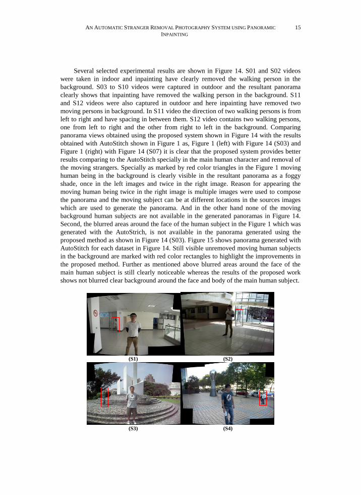
Figure 14. Experimental results, for each video source video frames are shown in top
and the resultant panorama is shown in bottom.
AN AUTOMATIC STRANGER REMOVAL PHOTOGRAPHY SYSTEM USING PANORAMIC
INPAINTING
15
Several selected experimental results are shown in Figure 14. S01 and S02 videos
were taken in indoor and inpainting have clearly removed the walking person in the
background. S03 to S10 videos were captured in outdoor and the resultant panorama
clearly shows that inpainting have removed the walking person in the background. S11
and S12 videos were also captured in outdoor and here inpainting have removed two
moving persons in background. In S11 video the direction of two walking persons is from
left to right and have spacing in between them. S12 video contains two walking persons,
one from left to right and the other from right to left in the background. Comparing
panorama views obtained using the proposed system shown in Figure 14 with the results
obtained with AutoStitch shown in Figure 1 as, Figure 1 (left) with Figure 14 (S03) and
Figure 1 (right) with Figure 14 (S07) it is clear that the proposed system provides better
results comparing to the AutoStitch specially in the main human character and removal of
the moving strangers. Specially as marked by red color triangles in the Figure 1 moving
human being in the background is clearly visible in the resultant panorama as a foggy
shade, once in the left images and twice in the right image. Reason for appearing the
moving human being twice in the right image is multiple images were used to compose
the panorama and the moving subject can be at different locations in the sources images
which are used to generate the panorama. And in the other hand none of the moving
background human subjects are not available in the generated panoramas in Figure 14.
Second, the blurred areas around the face of the human subject in the Figure 1 which was
generated with the AutoStrich, is not available in the panorama generated using the
proposed method as shown in Figure 14 (S03). Figure 15 shows panorama generated with
AutoStitch for each dataset in Figure 14. Still visible unremoved moving human subjects
in the background are marked with red color rectangles to highlight the improvements in
the proposed method. Further as mentioned above blurred areas around the face of the
main human subject is still clearly noticeable whereas the results of the proposed work
shows not blurred clear background around the face and body of the main human subject.
(S1) (S2)
(S3) (S4)

W. G. C. W. KUMARA, TIMOTHY K. SHIH, AND SHIH-MING CHANG 16
(S5) (S6)
(S7) (S8)
(S9) (S10)
(S11) (S12)
Figure 15. Panorama generated from AutoStitch for the datasets in Figure 14.
Tripod was not used during the example capturing, simulating a general user. A PC
with 1.8 GHz CPU and 2 GB RAM is used for the processing. 5 frames were obtained
from video automatically to compose the panorama. To measure the performance of the
system, time taken in each phase in the above given PC setup is measured and shown in
Figure 16. Time consumed in the object segmentation phase is almost similar for S01 to
S10 videos since only one stranger was removed, and the time consumed in the same
phase for S11 and S12 is higher since two strangers were removed in both cases instead.
Similar time patterns can be observed in dynamic background inpainting as well, since
same constraints are applicable here with respect to the number of strangers inpainted.

AN AUTOMATIC STRANGER REMOVAL PHOTOGRAPHY SYSTEM USING PANORAMIC
INPAINTING
17
Time consumed in panorama generation phase is different for each video. The reason
could be the number of similar features detected in each frame in panorama generation.
Specially, the reason for considerably less time consumption in S01 and S02 videos could
be the less complexity in the source frames since it was captured indoor. Interestingly
S07 video as well consumed less time in the panorama generation phase even though it
was captured in outdoor. Comparatively less background complexity could be the reason
which makes less best matching feature points in different frames. Complete results set
can be accessed at http://video.minelab.tw/PanoramaInpainting.
Figure 16. Time taken in each phase of the proposed system in seconds for results
in Figure 14.
Current works are going on to further improve the computation time in order to
implement the proposed application for mobile devices. Comparatively less processing
power of such mobile devices is a main factor here. Y. Xiong and K. Pulli have proposed
a panorama generation application for mobile devices in [24]. But automatically
removing moving human subjects in the background is not considered in their work. With
respect to the GrabCut used in our proposed approach, in the solution proposed in [24]
only currently processing source image is kept in memory, which gives a better
performance. Instead our proposal is to use Cloud processing space in order to perform
the task fast. As an example Google Photos use cloud processing to perform different
image editing functions. In this way user video can be uploaded to Cloud, can perform
the panorama generation fast, and then can be prompted back to the user’s mobile device.
5. CONCLUSION AND FUTURE WORKS
This paper proposed a novel panorama generation method automatically removing
strangers from the background. The proposed system uses a GrabCut algorithm based
object segmentation method. If the system did not detect strangers automatically that the
user wants to remove from the panorama, she can select the intended stranger manually.
In dynamic background restoration of the obscured objects, a solution combining motion
estimation and video inpainting is used. The proposed method is effective and shows
better results in dynamic background restoration comparing to traditional video
inpainting methods. In panorama creation, the advantages of traditional panorama
creation and image stitching are combined in the proposed method. The experimental

W. G. C. W. KUMARA, TIMOTHY K. SHIH, AND SHIH-MING CHANG 18
results presented clearly demonstrate that the proposed method is effective in use. Further
based on the experimental results this would be an attractive and useful application to be
included in the cameras.
It is required to pay more attention to reduce the processing time in the panorama
creation phase occurred mainly due the time spent on image matching and feature
matching. So far this was implemented for Windows 7 platform only. It is planned to
implement and test on the mobile operating system platforms with Cloud backend
processing in order to improve the processing time. A proper solution to fill the empty
regions around the boundary of the panorama is another objective to be achieved in near
future.
REFERENCES
1. M. Brown and D. G. Lowe, “Recognising panoramas,” in Proceedings of the 9th
IEEE International Conference on Computer Vision, 2003, pp. 1218-1225.
2. M. Brown and D. G. Lowe, “Automatic panoramic image stitching using invariant
features,” International Journal on Computer Vision, vol. 74, pp. 59-73, 2007.
3. J. Yao and J. M. Odobez, “Fast human detection from videos using covariance
features,” 8th International Workshop on Visual Surveillance, 2008.
4. Y. T. Chen and C. S. Chen, “Fast human detection using a novel boosted cascading
structure with meta stages,” IEEE Transactions on Image Processing, vol. 17, pp.
1452-1464, Aug. 2008.
5. C. Rother, V. Kolmogorov, and A. Blake, “GrabCut: interactive foreground
extraction using iterated graph cuts,” ACM Transactions on Graph, vol. 23, pp. 309-
314, 2004.
6. S. Vicente, V. Kolmogorov, and C. Rother, “Graph cut based image segmentation
with connectivity priors,” in IEEE Conference on Computer Vision and Pattern
Recognition, 2008, pp. 23-28.
7. V. Vezhnevets and V. Konouchine, “GrowCut: interactive multi-label ND image
segmentation by cellular automata,” in Proceedings of Graphicon, 2005, pp. 150-
156.
8. Y. Y. Boykov and M. P. Jolly, “Interactive graph cuts for optimal boundary and
region segmentation of objects in N-D images,” in Proceedings of 8th International
Conference on Computer Vision, 2001, vol. 1, pp. 105-112.
9. K. A. Patwardhan, G. Sapiro, and M. Bertalmío, “Video inpainting under constrained
camera motion,” IEEE Transactions on Image Processing, vol. 16, pp. 545-553, Feb.
2007.
10. Y. Wexler, E. Shechtman, and M. Irani, “Space-time completion of video,” IEEE
Transactions on Pattern Analysis and Machine Intelligence, vol. 29, pp. 463-476,
Mar. 2007.
11. N. C. Tang, C. T. Hsu, C. W. Su, T. K. Shih, and H. Y. M. Liao, “Video inpainting
on digitized vintage films via maintaining spatiotemporal continuity,” IEEE
Transactions on Multimedia, vol. 13, pp. 602-614, Aug. 2011.
12. C. H. Ling, C. W. Lin, C. W. Su, Y. S. Chen, and H. Y. M. Liao, “Virtual contour
guided video object inpainting using posture mapping and retrieval,” IEEE

AN AUTOMATIC STRANGER REMOVAL PHOTOGRAPHY SYSTEM USING PANORAMIC
INPAINTING
19
Transactions on Multimedia, vol. 13, pp. 292-302, Apr. 2011.
13. M. Ebdelli, C. Guillemot, and O. Le Meur, “Examplar-based video inpainting with
motion-compensated neighbor embedding,” in 19th IEEE International Conference
on Image Processing, 2012, pp. 1737-1740.
14. S. Xiaoming, Y. Xiaoyang, Y. Shuchun, G. Yanxia, M. Xiaoliang, Y. Yang, and L.
Yanan, “Video inpainting model for camera motion based on improved background
subtraction method,” in International Conference on Measurement, Information and
Control, 2013, pp. 299-303.
15. M. Ghorai, P. Purkait, and B. Chanda, “A fast video inpainting technique,” in
Pattern Recognition and Machine Intelligence, vol. 8251, pp. 430-436, 2013.
16. C. H. Cheung and L. M. Po, “Novel cross-diamond-hexagonal search algorithms for
fast block motion estimation,” IEEE Transactions on Multimedia, vol. 7, pp. 16-22,
Feb. 2005.
17. B. Postle and H. Dersch, “Panorama tools”, http://panotools.sourceforge.net, 2013.
18. S. Fazli, H. M. Pour, and H. Bouzari, “Particle filter based object tracking with sift
and color feature,” in 2nd International Conference on Machine Vision, 2009, pp.
89-93.
19. W. L. Zhao and C. W. Ngo, “Scale-rotation invariant pattern entropy for keypoint-
based near-duplicate detection,” IEEE Transactions on Image Processing, vol. 18,
pp. 412-423, Feb. 2009.
20. Y. Lu, L. Wang, R. Hartley, H. Li, C. Shen, “Multi-view human motion capture with
an improved deformation skin model,” Digital Image Computing: Techniques and
Applications (DICTA), 2008, pp. 420-427.
21. J. M. Morel and G. Yu, “ASIFT: a new framework for fully affine invariant image
comparison,” SIAM Journal on Imaging Sciences, vol. 2, pp. 438-469, 2009.
22. H. Bay, T. Tuytelarrs, L. V. Gool, “SURF: speeded up robust features,” in 9th
European Conference on Computer Vision, 2006, vol. 3951, pp. 404-417.
23. H. Bay, A. Ess, T. Tuytelarrs, L. V. Gool, “Speeded-up robust features (SURF),”
Computer Vision and Image Understanding, vol. 110, pp. 346-359, 2008.
24. Y. Xiong and K. Pulli, “Fast image stitching and editing for panorama painting on
mobile phones,” IEEE Computer Society Conference on Computer Vision and
Pattern Recognition Workshops, 2010, pp. 47-52.
25. B. Heigl, R. Koch, M. Pollefeys, J. Denzler, and L. V. Gool, “Plenoptic modeling
and rendering from image sequences taken by hand-held camera,” in
Mustererkennung, pp. 94-101, 1999.
26. A. Criminisi, I. Reid, and A. Zisserman, “A plane measuring device,” Image and
Vision Computing, vol. 17, pp. 625-634, 1999.
27. S. Avidan and A. Shamir, “Seam carving for content-aware image resizing,” ACM
Transactions on Graphics, vol. 26, 2007.
28. T. K. Shih, N. C. Tang, J. N. Hwang, “Exemplar-based video inpainting without
ghost shadow artifacts by maintaining temporal continuity,” IEEE Transactions on
Circuits, Systems and Video Technology, vol. 19, pp. 347-360, Mar. 2009.
29. T. K. Shih, N. C. Tang, J. C. Tsai, J. N. Hwang, “Video motion interpolation for
special effect applications,” IEEE Transactions on Systems, Man and Cybernetics.
C, Application. Reviews, vol. 41, pp. 720-732, Sept. 2011.
30. N. C. Tang, C. T. Hsu, C. W. Su, T. K. Shih, H. Y. M. Liao, “Video inpainting on

W. G. C. W. KUMARA, TIMOTHY K. SHIH, AND SHIH-MING CHANG 20
digitized vintage films via maintaining spatiotemporal continuity,” IEEE
Transactions on Multimedia, vol. 13, pp. 602-614, Aug. 2011.
31. T. K. Shih, R. C. Chang, Y. P. Chen, “Motion picture inpainting on aged films,” in
Proceedings of 13th Annual ACM International Conference on Multimedia,
Singapore, 2005, pp. 319-322.
32. T. K. Shih, N. C. Tang, J. C. Tsai, H. S. Zhong, “Video falsifying by motion
interpolation and inpainting,” in IEEE Computer Society Conference on Computer
Vision and Pattern Recognition, Anchorage, AK, 2008, pp. 1-8.
33. T. K. Shih, N. C. Tang, W. S. Yeh, T. J. Chen, W. Lee, “Video inpainting and
implant via diversified temporal continuations,” in Proceedings of 14th Annual ACM
International Conference on Multimedia, Santa Barbara, CA, 2006, pp. 133-136.
34. S. Vassiliadis, E. A. Hakkennes, J. S. S. M. Wong, and G. G. Pechanek, “The sum-
absolute-difference motion estimation accelerator,” in 24th EUROMICRO
Conference, 1998, pp 559-566.
35. A. Criminisi, P. Perez, K. Toyama, “Region filling and object removal by exemplar-
based image inpainting,” IEEE Transactions on Image Processing, vol. 13, pp.
1200-1212, Sept. 2004.
36. Z. Tauber, Z. N. Li, and M. S. Drew, “Review and preview: disocclusion by
inpainting for image-based rendering.” IEEE Transactions on Systems Man and
Cybernetics C, Application Reviews, vol. 37, pp. 527-540, July 2007.
37. Z. Xu and J. Sun, “Image inpainting by patch propagation using patch sparsity,”
IEEE Transactions on Image Processing, vol. 19, pp. 1153-1165, May 2010.
38. P. Jidesh and A. A. Bini, “A curvature-driven image inpainting approach for high-
density impulse noise removal,” Arabian Journal on Science and Engineering, pp. 1-
23, Mar. 2013.
39. P. Arias, G. Facciolo, V. Caselles, and G. Sapiro, “A variational framework for
exemplar-based image inpainting,” International Journal on Computer Vision, vol.
93, pp. 319-347, July 2011.
40. A. Bugeau, M. Bertalmío, V. Caselles, and G. Sapiro, “A comprehensive framework
for image inpainting,” IEEE Transactions on Image Processing, vol. 19, pp. 2634-
2645, Oct. 2010.
W. G. C. W. Kumara is currently reading for the Ph. D. at the
Department of Computer Science and Information Engineering,
National Central University (NCU), Taiwan (R.O.C.). He acquired his
Masters and Bachelors respectively from Asian Institute of
Technology (AIT), Thailand and Faculty of Engineering, University of
Ruhuna, Sri Lanka. Currently he is on leave from South Asian Institute
and Technology and Medicine (SAITM), Sri Lanka. His research
interests are in image processing and computer vision.
Timothy K. Shih is a Professor at the Department of Computer
Science and Information Engineering, National Central University,
Taiwan. Before that he was the Chair of Dept. of CSIE, Tamkang
University, Taiwan. Prof. Shih is a fellow of IET, a senior member of

AN AUTOMATIC STRANGER REMOVAL PHOTOGRAPHY SYSTEM USING PANORAMIC
INPAINTING
21
ACM, a senior member of IEEE, and also serves for the Educational Activities Board of
the Computer Society. His current research interests include multimedia computing,
human computer interaction and distance learning.
Shih-Ming Chang is a Ph. D. student at Department of
Computer Science and Information Engineering of Tamkang
University, Taiwan. He acquired the Master degree in Department of
Computer Science and Information Engineering of Tamkang
University of Taiwan in 2009. His research interests are in the area of
computer vision, interactive multimedia and multimedia processing