Embed Size (px)
Citation preview

AN ARQ SCHEME USING FIXED-BOUNDARY SUBPACKETS
WITH PILOT SYMBOL ASSISTED MODULATION
FOR RAYLEIGH CHANNELS
Herman Man Hon Ng B.A.Sc., University of Toronto, 2005
A PROJECT SUBMITTED IN PARTIAL FULFILLMENT OF THE REQUIREMENTS FOR THE DEGREE OF
MASTER OF ENGINEERING
In the School of
Engineering Science
O Herman Man Hon Ng 2006
SIMON FRASER UNIVERSITY
FALL 2006
All rights reserved. This work may not be reproduced in whole or in part, by photocopy
or other means, without permission of the author.

APPROVAL
Name:
Degree:
Title of Project:
Herman Man Hon Ng
Master of Engineering
An ARQ Scheme Using Fixed-Boundary Subpackets with Pilot Symbol Assisted Modulation for Rayleigh Channels
Examining Committee:
Chair: Dr. Jie Liang Professor of the School of Engineering Science
Date Approved:
Dr. Paul Ho Senior Supervisor Professor of the School of Engineering Science
Dr. James Cavers Supervisor Professor of the School of Engineering Science

SIMON FRASER ' UNDVERSDTY 1 l bra ry
DECLARATION OF PARTIAL COPYRIGHT LICENCE
The author, whose copyright is declared on the title page of this work, has granted to Simon Fraser University the right to lend this thesis, project or extended essay to users of the Simon Fraser University Library, and to make partial or single copies only for such users or in response to a request from the library of any other university, or other educational institution, on its own behalf or for one of its users.
The author has further granted permission to Simon Fraser University to keep or make a digital copy for use in its circulating collection (currently available to the public at the "Institutional Repository" link of the SFU Library website <www.lib.sfu.ca> at: <http:llir.lib.sfu.calhandIe118921112>) and, without changing the content, to translate the thesislproject or extended essays, if technically possible, to any medium or format for the purpose of preservation of the digital work.
The author has further agreed that permission for multiple copying of this work for scholarly purposes may be granted by either the author or the Dean of Graduate Studies.
It is understood that copying or publication of this work for financial gain shall not be allowed without the author's written permission.
Permission for public performance, or limited permission for private scholarly use, of any multimedia materials forming part of this work, may have been granted by the author. This information may be found on the separately catalogued multimedia material and in the signed Partial Copyright Licence.
The original Partial Copyright Licence attesting to these terms, and signed by this author, may be found in the original bound copy of this work, retained in the Simon Fraser University Archive.
Simon Fraser University Library Burnaby, BC, Canada
Revised: Fall 2006

ABSTRACT
A novel scheme of ARQ protocol using fixed-boundary subpackets to partition a
packet for re-transmissions is presented. Monte Carlo simulations of transmitting PSAM
signals using QPSK over Rayleigh channels with up to 3% Doppler have been used to
evaluate the performance of the proposed technique. Benchmarking against an ARQ
protocol using CRC for error detection, this subpacket ARQ scheme provides up to 35%
and 7% better in throughput for packets that are longer than 1024 when the channel SNR
is greater than 25dB without Doppler and with 1% Doppler respectively. Future
extensions of this subpacket re-transmission scheme with PSAM may lead to higher
throughput in other ARQ protocols currently using CRC for error detection.
Keywords: ARQ; error detection; subpacket scheme; PSAM; Rayleigh channel
Subject Terms: Data transmission systems; digital communications; mobile
communications systems; wireless communication systems

ACKNOWLEDGEMENT
I wish to express my gratitude to Professor Paul Ho of Simon Fraser University
for providing me with the subject of this project, as well as his continuous encouragement
and guidance throughout the course of this research. Furthermore, I must thank Professor
James Cavers of Simon Fraser University for providing valuable feedback in
strengthening the reliability of the proposed protocol. I would also like to acknowledge
the generous support from TELUS Technology Strategy for providing the additional
computing facilities required in the final stages of this research.

TABLE OF CONTENTS
. . APPROVAL ...................................................................................................................... 11
... ABSTRACT ...................................................................................................................... 111
............................................................................................... ACKNOWLEDGEMENT iv
.................................................................................................. TABLE OF CONTENTS v
LIST OF TABLES ............................................................................................................ vi . . LIST OF FIGURES ........................................................................................................ VII
I . INTRODUCTION .......................................................................................................... 1
I1 . SYSTEM MODEL ........................................................................................................ 4 A . General Assumptions and Considerations ................................................................... 4 B . Additional Considerations of the Baseline Scheme .................................................... 5 C . Additional Considerations of the Proposed Scheme ................................................... 5
I11 . SIMULATION RESULTS ....................................................................................... 12 A . Threshold Settings .................................................................................................... 1 2 B . Throughput Analysis ................................................................................................. 13 C . Drop-Rate Analysis ................................................................................................... 18 D . Overall System Performance Analysis ...................................................................... 22
1) Throughput Comparison ........................................................................................ 22 2) Drop-Rate Comparison .......................................................................................... 26 3) Overall Performance Comparison .......................................................................... 28
IV . FUTURE EXTENSIONS .......................................................................................... 29
V . CONCLUSIONS ......................................................................................................... 30
APPENDICES .................................................................................................................. 31 Appendix A .................................................................................................................... 31 Appendix B .................................................................................................................... 36
REFERENCES ................................................................................................................ 41

LIST OF TABLES
Table 1.
Table 2.
Table 3.
Table 4.
Table 5.
Table 6.
Table 7.
Table 8.
Definitions of terms used in Figure 3 ................................................................ 6
Number of fixed-boundary subpackets for different packet and subpacket sizes ........ .... .. ..... ..... .. .............. .... .. ... . ..... .. ..... .. ....... .. .. ......... ... .. ...... .. 10
Identification overhead based on different frame and subpacket sizes . . . . . . . . . . . l l
Throughput gain for packet length of 1400 at 25dB with 0%, 1% and 3% Doppler.. . . . . . . . . . . . . . . . . . . . .. . . . . . . . . . . . . . . . . . . . . . . . . . . . . . . . . . . . . . . . . . . . . . . . . . . . . . . . . . . . . . . . . . . . . . .. . . . . . . . -23
Throughput gain for packet length of 560 at 25dB without Doppler .............. 24
Throughput gain for packet length of 280 at 25dB without Doppler .............. 25
Drop-rate reduction for packet length of 1400 at 25dB with 0%, 1 % and 3% Doppler .... .. . . . . . . . . . . . . . . . . . . . . . . . . . . . . . . . . . . . . . . . . . . . . . . . . . . . . . . . . . . . . . . . . . . . . . . . . . . .. . . . . . . . . . . . . -27
Summary of the performance gain for the proposed scheme at 25dB SNR .... .. . . . . . . . . . . . . . . . . . . . . . . . . . . . .. . . . . . . . . . . . . . . . . . . . . . . . . . . . . . . . . . . . . . . . . . . . . . . , . .. . . . . . . . . . . . . . . . . . . . . . . . . . . . . .28

LIST OF FIGURES
Figure 1 . Figure 2 . Figure 3 . Figure 4 . Figure 5 . Figure 6 . Figure 7 . Figure 8 . Figure 9 .
Packet structure of the baseline scheme ............................................................ 5
................. Frame structure of the proposed fixed-boundary subpacket scheme 6
Thresholds of Irl and Ig*rJ for error detection .................................................. 12
.............. Throughput for packet length of 1400: 15dB to 25dB channel SNR 15
.............. Throughput for packet length of 1400: 21 dB to 25dB channel SNR 15
................ Throughput for packet length of 560: 15dB to 25dB channel SNR 16
................ Throughput for packet length of 560: 2 1 dB to 25dB channel SNR 16
................ Throughput for packet length of 280: 1 5dB to 25dB channel SNR 17
................ Throughput for packet length of 280: 21dB to 25dB channel SNR 17
Figure 1
Figure 1
Figure 1
Figure 1
Figure 1
0 . Drop-rate for packet length of 1400: 15dB to 25dB channel SNR .................. 19
1 . Drop-rate for packet length of 1400: 2 1 dB to 25dB channel SNR .................. 19
2 . Drop-rate for packet length of 560: 15dB to 25dB channel SNR .................... 20
3 . Drop-rate for packet length of 560: 21dB to 25dB channel SNR .................... 20
4 . Drop-rate for packet length of 280: 15dB to 25dB channel SNR .................... 21
Figure 15 . Drop-rate for packet length of 280: 2 1 dB to 25dB channel SNR .................... 21
Figure 16 . Throughput gain for packet length of 1400 at 25dB ........................................ 23
Figure 17 . Throughput gain for packet length of 560 at 25dB .......................................... 24
Figure 18 . Throughput gain for packet length of 280 at 25dB .......................................... 25
Figure 19 . Drop-rate reduction for packet length of 1400 at 25dB ................................... 26
Figure 20 . Drop-rate reduction for packet length of 560 at 25dB ..................................... 27
Figure 2 1 . Throughput gain for packet length of 1400 at 15dB to 17dB .......................... 31
Figure 22 . Throughput gain for packet length of 1400 at 19dB to 25dB .......................... 32
Figure 23 . Throughput gain for packet length of 560 at 15dB to 2 1 dB ............................ 33
Figure 24 . Throughput gain for packet length of 560 at 23dB to 25dB ............................ 34
Figure 25 . Throughput gain for packet length of 280 at 15dB to 17dB ............................ 34
Figure 26 . Throughput gain for packet length of 280 at 19dB to 25dB ............................ 35
Figure 27 . Drop-rate reduction for packet length of 1400 at 15dB to 17dB ..................... 36
vii

Figure 28 . Drop-rate reduction for packet length of 1400 at 19dB to 25dB ..................... 37
Figure 29 . Drop-rate reduction for packet length of 560 at 15dB to 21dB ....................... 38
Figure 30 . Drop-rate reduction for packet length of 560 at 23dB to 25dB ....................... 39
Figure 3 1 . Drop-rate reduction for packet length of 280 at 15dB to 17dB ....................... 39
Figure 32 . Drop-rate reduction for packet length of 280 at 19dB to 25dB ....................... 40
... Vll l

I. INTRODUCTION
Automatic Repeat reQuest (ARQ) protocol involves a receiver using a feedback
mechanism to request the transmitter to re-send the packets detected as erroneous. Cyclic
redundancy check (CRC) is typically used for detecting errors hence determining whether
the received packets are the error-free version of the original message transmitted. File
transfer protocol (FTP) and the Institute of Electrical and Electronics Engineers (IEEE)
802.1 l x Wireless Local Area Network (LAN) standards are two of the many applications
using CRC in ARQ [I]. When the CRC does not check at the receiver, this information
will either be explicitly or implicitly fedback from the receiver to the transmitter
requesting a re-transmission of the erroneous message [2,3]. Existing ARQ protocols
vary in the maximum number of repeat requests before dropping a packet for re-
transmissions, the content of the packet during the re-transmissions, as well as the
handling of the multiple packets received from the requested re-transmissions [4].
Conventional pure-ARQ uses an error detecting code and a feedback channel to
initiate re-transmission of any packets received in error. Over the years, there have been
numerous extensions in pure-ARQ protocol. Today, pure-ARQ remains attractive
because including only error detection code has a lower overhead than using error
correction coding. Nevertheless, pure-ARQ is generally combined with a moderate
degree of error correction coding (Hybrid ARQ) in order to increase the system
throughput by reducing the number of retransmissions required [5]. At a high level
overview, there are three types of Hybrid ARQ (HARQ). Type-I HARQ mostly
combines pure-ARQ and forward error correction (FEC) coding; Type-I1 HARQ or
Chase Combining (CC), is a solution of combining multiple copies of the same signals
using maximal ratio combining (MRC); Type-I11 HARQ involves incremental
redundancy (IR) whereby the additional coded parities are retransmitted [6,7]. 1X
Evolution DataNoice (1XEV-DV) and High-speed Downlink Packet Access (HSDPA)
are two of the many wireless communication standards that have adopted various forms
of HARQ protocols [S].
Researches in various ARQ and HARQ schemes have been on-going over the past
few decades. Some of the developments in the past few years include various rate-
adaptive ARQ protocols [I], an HARQ scheme using product code comprised of two
CRC codes [9], the determining of optimum packet size dynamically based on a given
bit-error-rate (BER) [lo], the use of arithmetic coding to control the amount of
redundancy in re-transmission [2], employing adaptive modulation and coding (AMC) in
HARQ [l 11, as well as leveraging cooperative relaying extension in ARQ [4].
Until recently, most of the work continues to optimize ARQ protocols by
considering the re-transmission of the packet in its entirety. Extending the packet
combining system using Viterbi Decoder by [12], [13] recently proposed an adaptive
system in determining the optimum number of subpackets used in a convolutionally
coded system with binary-phase-shift keying (BPSK) subjected to additive white
Gaussian noise (AWGN).
In this project, a novel scheme for pure-ARQ in Rayleigh fading channels using
fixed-boundary subpacket partitioning of a packet for re-transmissions to improve the

overall channel throughput is presented. Pilot symbol assisted modulation (PSAM)
signals are transmitted using quaternary-phase-shift-keying (QPSK) and Rayleigh
channels with fade rates up to 3% have been used to evaluate the performance of the
proposed scheme. In the proposed technique, the magnitude of the received signals, Irl,
and the magnitude of the compensated received signals, Ig*rl are used as thresholds in
determining the re-transmission requirement. The baseline of comparison is an ARQ
protocol with CRC for error detection.
Section I1 discusses the system models of the baseline scheme and the proposed
scheme. The first two subsections in section I11 present the Monte Carlo simulation
results of the throughputs and the drop-rates for the baseline system as well as the
proposed systems at different signal-to-noise ratios (SNRs) with different fade rates using
various subpacket sizes. Section 1II.C compares the performance between the baseline
and the proposed schemes. Section IV recommends the possible extensions based on the
results presented and section V concludes the project.

11. SYSTEM MODEL
This section is organized in the following manner. The general assumptions and
considerations common to both the baseline and the proposed schemes will first be
presented. Subsection 1I.B presents the CRC scheme used as the benchmark, and
subsection 1I.C outlines the details of the proposed subpacket scheme.
A. General Assumptions and Considerations
The assumptions and considerations made in this project are as follows:
The channel conditions in the feedback (uplink) direction (i.e., from the receiver
to the transmitter), and the feed-fonvard (downlink) direction (i.e., from the
transmitter to the receiver) are reciprocal.
The maximum total number of transmission is six times including the initial
transmission (i.e., maximum of five re-transmissions).
A pilot spacing of seven and a filter length of eleven are chosen to be the
parameters of the PSAM to accommodate normalized fade rates of up to 3% [14].
The size of the overhead contained in a packet for synchronization at the receiver
is considered negligible.
The system uses quaternary phase-shift-keying (QPSK) constellations.
The Rayleigh channel SNRs studied are 15dB, 17dB, 19dB, 21dB, 23dB, and
25dB.
The normalized fade rates studied are 0, 1%, and 3%.

In this project, three packet sizes of 280, 560, and 1400 symbols are considered.
Packet sizes are chosen to be multiples of 7 to facilitate the composition of the individual
PSAM frames of length 7.
B. Additional Considerations of the Baseline Scheme
In the baseline scheme, the receiver sends out an acknowledgement (ACK) when
the CRC of a packet is successful at the receiver. In the case of a failed CRC, the entire
packet will be re-transmitted from the transmitter to the receiver until either an ACK is
achieved or the maximum number of transmissions has been reached. In this project, the
CRC-16 Consultative Committee of International Telephone and Telegraph (CRC16-
CCITT) standard was chosen as the benchmark scheme. Specifically, the generator
polynomial is 0x1 021 in hexadecimal notation or 016 + 0 1 2 + 0j + 1 1131.
Figure 1 shows the packet structure of the baseline scheme. The terms used in the
diagram will be referenced when presenting the throughput analysis calculations in
section 1II.B.
Figure 1. Packet structure of the baseline scheme
C. Additional Considerations of the Proposed Scheme
Unlike the baseline scheme where the entire packet will be re-transmitted when it
is not acknowledged before timer expiry, a frame of the proposed scheme may contain

subpackets belonging to one or more packets. The subpackets transmitted in each frame
will be assembled at the receiver based on its subpacket and packet sequence numbers.
The method of partitioning a packet into subpackets will be discussed later in this section.
Figure 2 shows the fiame structure of the subpacketing scheme and Table 1 explains the
terms used in the diagram.
information and pilot-symbols
control-CRC --- --- SUBPACKET SUBPACKET SUBPACKET SUBPACKET SUBPACKET control ~nlo (feedback)
f Figure 2. Frame structure of the proposed fixed-boundary subpacket scheme
Table 1. Definitions of terms used in Figure 3
control info (feedback)
fiame - size
packet-size
pkt seq#
pkt seq# ACK
subpkt seq#
CRC for the control-info
A term for describing subpkt seq#, subpkt seq# ACK, pkt seq#, and pkt seq# ACK collectively
A combinations of subpackets with information belonging to one or more packets
A stream of symbols containing information belonging to a single packet
Mod-8 (3 bits) sequence numbers indicating which packet does a subpacket belongs to. Mod-6 is chosen because the maximum number of re-transmission before dropping a subpacket is 5. Every subpacket has its own pkt seq#.
Mod-2 sequence numbers of the most recent correctly received packets
CRC for packet-size in the baseline scheme.
For the proposed scheme, it is applied at the receiver to an assembled packet (i.e., a concatenation of subpackets belonging to the same packet)
Mod-2 sequence numbers of the subpackets

I sync O/H I Synchronization overhead
subpkt seq#
In the proposed scheme, PSAM is used to estimate channel state information
(CSI) at the receiver. Leveraging the CSI, the receiver will check whether Irl and Ig*rl
from the received signals both exceed their respective threshold values set a priori at the
receiver. For a symbol that failed to meet the thresholds, it will be re-transmitted as part
of the subpackets that it belongs to. The rationale of using values of Irl and Ig*rl as the
error-detection thresholds at the subpacket level will be discussed later in this section.
The interaction between using the threshold criteria in identifying subpackets requiring
re-transmission, and having CRC at the receiver to detect errors for a packet (not a frame)
will now be discussed. It is to note that for this proposed scheme, the use of CRC at the
receiver scheme, in combination with using the CSI from PSAM, ensures that the error
detection capability is the same as the baseline scheme.
Mod-2 sequence numbers of the most recent correctly received subpackets
When A sends messages to B, B checks the CRC of each assembled packet. At
this time, one of three scenarios will occur prior to B feeding back any sequence numbers
or acknowledgement (control-info) to A.
1) I f a packet CRC @kt - CRC) is successful for an assembled packet at B: B
acknowledges the subpackets belonging to this packet by updating the
corresponding ACK parts of the subpacket sequence numbers (subpkt seq#) and
packet sequence numbers @kt seq#). When the CRC of an assembled packet is
successful, the subpackets belonging to this packet will not be flagged for re-
transmission even if these subpackets failed the threshold criteria. Other
subpackets in the same frame belonging to other packets will be treated
according to the outcome of their respective pkt-CRC.
2 ) If a packet CRC @kt - CRC) fails for an assembled packet at B and some of the
subpackets belonging to this packet also failed the threshold criteria: B
acknowledges the subpackets belonging to this packet that passed the threshold
criteria. For the subpackets belonging to this packet that failed the threshold
criteria, B will receive a re-transmission after timer expiry at A. Other
subpackets in the same frame belonging to other packets will be treated
according to the outcome of their respective pkt-CRC.
3) I f a packet CRC @kt_CRC) fails for an assembled packet at B and all of the
subpackets belonging to this packet passed the threshold criteria: B does not
acknowledge the subpackets belonging to this packet that passed the threshold
criteria. B will therefore receive a re-transmission of these subpackets after timer
expiry at A. Other subpackets in the same frame belonging to other packets will
be treated according to the outcome of their respective pkt-CRC. This scenario
should be a rare case.
When A receives the control-info from B, one of two scenarios will occur
depending on the received control-CRC at A.
1 ) Ifthe control CRC (control - CRC) fails at A: A re-sends the entire frame sent to B
in the previous time-slot.

2 ) I f the control CRC (control-CRC) passes at A: For the subpackets with
acknowledged subpacket sequence numbers (i.e., subpkt seq# equals to subpkt
seq# ACK), new subpackets get slotted into these positions. For the subpackets
without acknowledged subpacket sequence numbers (i.e., subpkt seq# does not
equal to subpkt seq# ACK), the same subpackets will be re-transmitted in these
positions.
In choosing the parameters to be used for the threshold criteria, three separate
scenarios using only one parameter (i.e., using only Irl for one case, only Ig*l for another
case, and only Ig*r( for the third case) were initially considered. The conclusion was that
using one parameter for error flagging will quickly require all the symbols to be re-
transmitted consequently decreasing the throughput of the system significantly.
Therefore, this subpacket scheme uses both values of Irl and Ig*rl as the error-detection
thresholds instead of using only JrJ or Ig*rl. The Irl and Ig*rl threshold values are
determined empirically through the Monte Carlo simulations prior to the numerical
investigation of throughput and drop-rates.
In addition to the assumptions and considerations already covered, the proposed
scheme divides the packet into smaller subpackets by using fix boundaries. For instance,
a packet length of 280 with subpacket size of 5 results in 56 subpackets for the packet.
Specifically, the second subpacket consists of the 6th to the loth symbols of the packet.
Should any symbols in this second subpacket failed to surpass the two threshold criteria,
the 6" to the loth symbols grouped as the second subpacket will be re-transmitted. In
other words, one acknowledgement (subpkt seq# ACK) is used for acknowledging one or

multiple erroneous symbols within the same fixed-boundary subpacket before timer
expiry. Contrasting to the use of dynamic boundaries where one possible implementation
is to always transmit two adjacent symbols on both sides of a flagged symbol, the choice
of using fixed-boundary subpackets, reduces the overhead required in providing sequence
numbers and the respective acknowledgement. Using fix boundaries therefore eliminates
another layer of complexity in this proof-of-concept investigation. In the proposed
scheme, the subpacket sizes with fixed-boundary are 4, 5, 7, 10, 14, 28, 70, and 140.
With the three packet sizes studied, the number of subpackets depends on the subpacket
and packet sizes under consideration. Table 2 summarizes the settings considered in this
project.
Table 2. Number of fixed-boundary subpackets for different packet and subpacket sizes
Moreover, the number of control symbols (i.e., control-info), containing
information on sequence numbers and acknowledgements, to be taken into account when
calculating the channel throughput is dependent on the packet and subpacket size studied.
For each subpacket, 1 bit is allocated for subpkt seq#, subpkt seq# ACK, and pkt seq#
ACK; 3 bits are allocated for pkt seq#. With 2 bits in each QPSK symbol, every
subpacket is associated with three symbols of control information. In order words, for
each scenario considered in Table 2, the identification overhead associated is three times
Number of Subpackets
Subpacket Size
Packet Size
280 560 1400
140 2 4 10
4 70 140 350
10 28 56 140
5 56 112 280
14 20 40 100
7 40 80
200
28 10 20 50
70 4 8
20

the number of subpackets in the setting under consideration. Table 3 outlines the number
of symbols required to relay re-transmission information to the transmitter.
Table 3. Identification overhead based on different frame and subpacket sizes
Number of Symbols for control-info
Subpacket Size
Frame Size
280 560 1400
4 210 420 1050
5 168 336 840
7 120 240 600
14 60 120 300
10 84 168 420
28 30 60 150
70 12 24 60
140 6 12 30

111. SIMULATION RESULTS
The Monte Carlo simulations of this project are implemented using MatLab.
Subsection A discusses the results of setting the thresholds. Subsections B and C analyze
the throughput and drop-rate respectively. Subsection D discusses the overall system
performance. As discussed in the previous section, the error detection reliability of the
proposed scheme is the same as using CRC. Consequently, a subsection analyzing the
undetected error probabilities is not required to warrant the overall system performance.
A. Threshold Settings
Figure 3. Thresholds of 14 and Ig*4 for error detection

Figure 3 presents the absolute threshold values (i.e., not normalized values) used
for this project. In scenarios where Doppler does not exist, the thresholds for Irl have an
inverse relationship with the channel SNR. Contrasting to the no Doppler scenarios, the
thresholds for Irl in the 1% and 3% Doppler scenarios have a direct relationship with the
channel SNR. The higher thresholds in the presence of Doppler can be explained due to
filter mismatch.
On the other hand, the thresholds for Ig*rl appear to be less sensitive to the
channel SNR. This is expected because the values of Ig*rl in PSAM have already
accounted for the CSI, including the channel SNR, implicitly. The thresholds of Ig*rl
serve as a joint error detection criterion to reduce the number of false alarms. In this
project, the thresholds of Ig*rl and Irl are determined empirically. Consequently, one
possible extension to this work is to threshold the magnitude of the real and imaginary
parts of the maximum-likelihood decision variables at the receiver analytically using
techniques discussed in [15].
B. Throughput Analysis
From the results of the Monte Carlo simulations, the average number of
transmissions per packet for the CRC scheme, or per subpacket for the proposed scheme,
is obtained for a given channel SNR and a normalized fade rate. The average number of
transmissions for a packet using the baseline scheme is represented by Nc, ; the same
quantity using the proposed subpacket scheme is represented by N,,,,,,=, . A drop-rate is
also calculated for the packets that were not successfully transmitted after five re-
transmissions and those results are presented in the next subsection.

In the baseline scheme, using the notations introduced in Figure 1, the throughput,
qCRC, is calculated by:
(packet - size - pilot - symbols - feedback) VCRC -
NcRc x (packet - size + pkt - CRC)
In the proposed scheme, using the notations introduced in Figure 2, the
throughput, q7subp~=x, is calculated by:
- ( fiame - size - pilot - symbols - control - in. fo - control - CRC) ?'sub+=x =
Nsubpkt=x x (fiame - size)
Figures 4 to 9 capture the throughput results obtained from the simulations. In the
legends of the plots, "Subpkt Size: x" and "CRC-16 Baseline" denote the proposed
scheme with a subpacket size of x and the benchmark CRCl6-CCITT scheme
respectively.
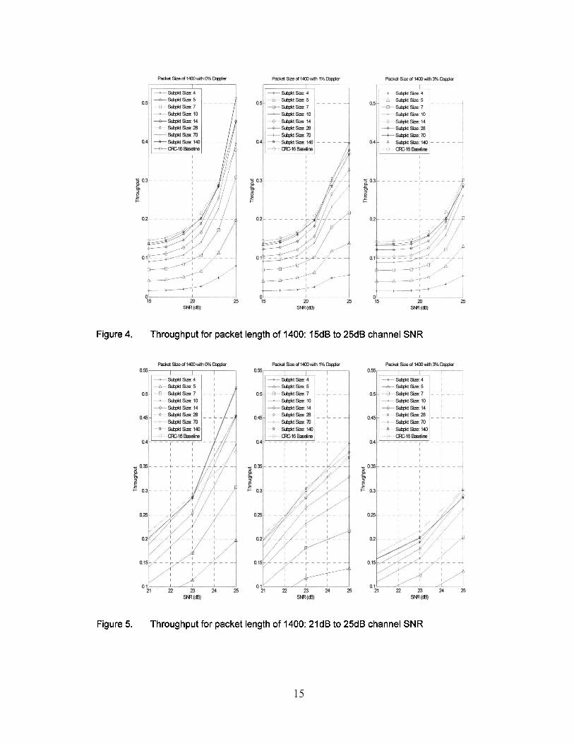
Figure 4. Throughput for packet length of 1400: 15dB to 25dB channel SNR
Figure 5. Throughput for packet length of 1400: 21dB to 25dB channel SNR

Figure 6. Throughput for packet length of 560: 15dB to 25dB channel SNR
Figure 7. Throughput for packet length of 560: 21dB to 25dB channel SNR

SJ? (dl) = (dl)
Figure 8. Throughput for packet length of 280: 15dB to 25dB channel SNR
Figure 9. Throughput for packet length of 280: 21dB to 25dB channel SNR
The results to be noted are that at 25dB SNR, there exist solutions for the fixed-
boundary subpacket sizes to have a comparable or higher throughput than that of the
baseline CRC case. Moreover, Figures 4 and 5 show that for a packet length of 1400,
there exists subpacket sizes of which a throughput higher than the baseline can be
achieved at a SNR of 25dB. The implications of these results will be examined at a
closer look in subsection D after the presentation of the drop-rate in the next subsection.
C. Drop-Rate Analysis
The drop-rate is the quotient for the number of dropped packets divided by the
number of packets attempted for transmissions. Understanding the drop-rate of the
proposed scheme is important because a novel technique with only a higher throughput
will be a less attractive alternative than one with both better throughputs and lower drop-
rates. Figures 10 to 15 capture the drop-rate results obtained from the simulations.
Similar to Figures 4 to 9, "Subpkt Size: x" and "CRC-16 Baseline" in the legends denote
the proposed scheme with a subpacket size of x and the benchmark CRC16-CCITT
scheme respectively.

Figure 10. Drop-rate for packet length of 1400: 15dB to 25dB channel SNR
Figure 11. Drop-rate for packet length of 1400: 21dB to 25dB channel SNR

Padce!SzedSEOHithl%~~
+s&MSze5
- w W l O U s & M S z E l 4
t s 4 i d s z S r n
- ~ ~ 1 4 0 -'-CRC16 W i n e
Figure 12. Drop-rate for packet length of 560: 15dB to 25dB channel SNR
Figure 13. Drop-rate for packet length of 560: 21dB to 25dB channel SNR

Figure 14. Drop-rate for packet length of 280: 15dB to 25dB channel SNR
Figure 15. Drop-rate for packet length of 280: 21dB to 25dB channel SNR

The results to be noted are that at 25dB SNR, there exist solutions for the fixed-
boundary subpacket sizes to have a comparable or lower drop-rate than that of the
baseline CRC case. The implications of these results in combination with the throughput
results will be examined in the next subsection.
D. Overall System Performance Analysis
In assessing the overall ARQ protocol performance of two schemes, the error
detection capability, the throughput and the drop-rate are crucial metrics. Because the
error detection capability for the proposed scheme is the same as the baseline scheme,
only a higher throughput and a lower drop-rate together may qualify this proposed ARQ
scheme to be an attractive proposition.
1) Throughput Comparison
Figures 16 to 18 show that the proposed scheme either has the same or a better
throughput at SNR of 25dB for some subpacket sizes studied.
Expressed in percentage, a positive throughput gain is the throughput
improvement that the proposed scheme has over the baseline scheme. For instance, if the
proposed scheme has a throughput of 75% while the baseline scheme is at 60%, the
throughput gain reported will be 25%. Based on the throughput gain in the proposed
scheme fiom the baseline as shown in Figure 16, Table 4 shows the results for a packet
size of 1400, at 25dB channel SNR with the fade rates studied

Figure 16. Throughput gain for packet length of 1400 at 25dB
Table 4. Throughput gain for packet length of 1400 at 25dB with 0%, 1% and 3% Doppler
I Fade 1 0% 1 -78.91 1 -48.17 1 -18.89 1 4.17 1 19.35 1 35.16 1 34.61 1 19.79 1 Throughput I Gain in %
I Rate I 1 % 1 -84.82 1 -62.97 1 -41.80 1 -22.66 1 -1 1.84 1 1.64 1 6.73 1 -1.22 1
In Table 4, the simulation results indicate that at 25dB without Doppler, using
subpacket sizes of 28 and 70 for a packet length of 1400 leads to a throughput gain of
35%. Moreover, at a moderate Doppler of 1%, there remains over 6.5% in throughput
gain when subpacket size of 70 is employed.
Subpacket Size of 1400 at 25dB SNR 4 1 5 7 I I 0 1 1 4 1 2 8 1 7 0 1 1 4 0

Figure 17. Throughput gain for packet length of 560 at 25dB
Table 5 shows the throughput gain for a packet size of 560, at 25dB channel SNR
without Doppler from Figure 17. Using a subpacket size of 70 for a packet size of 560
achieves the best throughput result. The result, however, is only slightly better than the
baseline scheme with a 0.3% gain.
Table 5. Throughput gain for packet length of 560 at 25dB without Doppler
Throughput Gain in %
Fade Rate 0%
Subpacket Size of 560 at 25dB SNR 70
0.30 28
-5.39 140
-2.21 10
-28.94 7
-46.03 4
-88.64 14
-18.42 5
-67.79

Figure 18. Throughput gain for packet length of 280 at 25dB
From Figure 18, Table 6 shows the throughput gain for a packet size of 280, at
25dB channel SNR without Doppler. With the identification overhead required for the
proposed scheme, a packet size of 280 did not outperform the baseline scheme using the
subpacket sizes studied.
Table 6. Throughput gain for packet length of 280 at 25dB without Doppler
For completeness, all other scenarios considered for the preparation of this project
Throughput Gain in %
Fade Rate 0%
are documented in Appendix A.
Subpacket Size of 280 at 25dB SNR 70
-12.56 4
-93.78 140
-12.21 10
-40.56 5
-75.51 14
-30.62 7
-55.76 28
-18.38

2) Drop-Rate Comparison
Expressed in percentage, a positive drop-rate reduction is the improvement that
the proposed scheme has over the baseline scheme with respect to the amount of dropped
data because of reaching the maximum number of times for re-transmission. For
instance, if the proposed scheme has a drop-rate of 60% while the baseline scheme is at
75%, the drop-rate reduction reported will be 20%. Figures 19 to 21 show the drop-rate
reduction for packet lengths of 1400,560 and 280 at a SNR of 25dB respectively.
Figure 19. Drop-rate reduction for packet length of 1400 at 25dB
Figure 19 presents the drop-rate reductions for the packet size of 1400, at 25dB
channel SNR with the fade rates studied. The results are tabulated in Table 7. At 25dB
without Doppler, using the subpacket sizes of 10 or greater, the drop-rate reduction

ranges from 84% to 99%. Moreover, at Doppler of 1% with subpacket size of 70, the
drop-rate reduction is over 60%.
Table 7. Drop-rate reduction for packet length of 1400 at 25dB with 0%, 1% and 3% Doppler
I Rate I 1% 194.87 191.05 182.39 180.69 178.96 167.22 162.90 127.73 1
Drop-Rate Reduction in %
Fade 1 0%
Figure 20 shows that for packet size of 560 25dB channel SNR with a fade rate of
0%, the drop-rate improvement is 74% when subpacket size of 70 is chosen.
Figure 20. Drop-rate reduction for packet length of 560 at 25dB
Subpacket Size of 1400 at 25dB SNR 4
99.98 5
99.93 7
99.71 10
99.57 14
99.32 28
98.94 70
95.51 140
84.04

Although other scenarios considered in this report also exhibit great improvement
in drop-rate, the plots are presented in Appendix B and are excluded from this subsection
because there are no throughput gains. Similar to the throughput analysis subsection, all
other drop-rate results considered for the preparation of this project are documented in
Appendix B.
3) Overall Performance Comparison
When a channel has a SNR of 25dB, employing the proposed scheme with
selected subpacket sizes lead to a lower drop-rate and an improvement in throughput. A
summary of notable results at 25dB presented in this subsection is in Table 8.
Table 8. Summary of the performance gain for the proposed scheme at 25dB SNR
Special attention should be paid to the results of scenarios without Doppler.
Without Doppler, the throughputs of the proposed scheme using the subpacket sizes
outlined in Table 8 are higher than or the same as the baseline scheme, with significant
improvement in the drop-rate reductions as well. The results lead to the possibility of
using of the proposed subpacket technique for deployment scenarios without fade rates.
Packet Size 1400
560
Doppler
0 1% 0
Subpacket Size
28 and 70 28 and 70
70
Throughput Gain 35%
1.6% and 6.7% 0.3%
Drop-Rate Reduction
99% and 96% 67% and 62%
74%

IV. FUTURE EXTENSIONS
There are several extensions to this investigation. One possible extension is to
analytically determine the threshold values as a function of PSAM parameters, packet
and subpacket sizes. Another extension is to use maximum ratio combining at the
receiver to improve the overall system performance. A third extension is to incorporate
the effects of co-channel interface and assess the feasibility of using this technique in
other ARQ schemes, such as the various HARQ schemes in fixed mobile applications, for
potential throughput improvement.

V. CONCLUSIONS
A novel scheme of ARQ protocol using fixed-boundary subpackets to partition a
packet for re-transmissions is presented. Monte Carlo simulations of transmitting PSAM
signals using QPSK over Rayleigh channels without Doppler, as well as with 1% and 3%
fade rates have been used to evaluate the performance of the proposed technique.
Benchmarking against an ARQ protocol using CRC 16-CCITT for error detection, this
subpacket ARQ scheme provides up to 35% and 7% better in throughput for packets of
1400 when the channel SNR is greater than 25dB without Doppler and with 1% Doppler
respectively. Moreover, lower drop-rates than the baseline scheme are found along with
the throughput improvement reported in this project. Future extensions of this subpacket
re-transmission scheme with PSAM may lead to higher throughput in other ARQ and
HARQ protocols.


Figure 22. Throughput gain for packet length of 1400 at 19dB to 25dB


Figure 24. Throughput gain for packet length of 560 at 23dB to 25dB
I I , I
o a, 40 m m m la, 14)
stFBcket-
Figure 25. Throughput gain for packet length of 280 at 15dB to 17dB


Appendix B
Appendix B contains the drop-rate of all the scenarios considered for the
preparation of this project.
Figure 27. Drop-rate reduction for packet length of 1400 at 15dB to 17dB

Figure 28. Drop-rate reduction for packet length of 1400 at 19dB to 25dB

Figure 29. Drop-rate reduction for packet length of 560 at 15dB to 21dB

Figure 30. Drop-rate reduction for packet length of 560 at 23dB to 25dB
41 I I I I I I I 0 20 40 W 83 lm 120 140
m e ( size
Figure 31. Drop-rate reduction for packet length of 280 at 15dB to 17dB

Figure 32. Drop-rate reduction for packet length of 280 at 19dB to 25dB

REFERENCES
T. Ji and W. Stark, "Rate-Adaptive Transmission Over Correlated Fading Channels," IEEE Transactions on Communications, vol. 53, no. 10, pp. 1663- 1670, Oct. 2005.
J. Chou and K. Ramchandran, "Arithmetic Coding-Based Continuous Error Detection for Efficient ARQ-Based Image Transmission," IEEE Journal on Selected Areas in Communications, vol. 1 8, no. 6, pp. 86 1-867, Jun. 2000.
J.-F. (T) Cheng, "Coding Performance of Hybrid ARQ Schemes," IEEE Transactions on Communications, vol. 54, no. 6, pp. 10 17- 1029, Jun. 2006.
E. Zimmermann, P. Herhold, G. Fettweis, "The Impact of Cooperation on Diversity-Exploiting Protocols," in IEEE 59th Vehicular Technologv Conference, 17-19 May 2004, vol. 1, pp. 41 0-414.
G. Wade, Coding Techniques: An Introduction to Compression and Error Control. New York City, NY, USA: Palgrave, 2000, p. 198.
Y. Wang, L. Zhang, and D. Yang, "Performance Analysis of Type I11 HARQ with Turbo Codes," in The 571h IEEE Semiannual Vehicular Technologv Conference, 22-25 Apr. 2003, vol. 4, pp. 2740-2744.
P. Frenger, S. Parkvall, and E. Dahlman, "Performance comparison of HARQ with Chase combining and incremental redundancy for HSDPA," in IEEE VTS 54th Vehicular Technologv Conference 2001,7-11 Oct. 200 1, vol. 3, pp. 1829- 1833.
H. Zheng and H. Viswanathan, "Optimizing the ARQ Performance in Downlink Packet Data Systems With Scheduling," IEEE Transactions on Wireless Communications, vol. 4, no.2, March 2005.
K. Sawai and S. Uebayashi, "A Hybrid ARQ for Data Transmission in Digital Mobile Radio," in IEEE 43rd Vehicular Technologv Conference, 18-20 May 1993, pp. 762-765.
S.S. Chakraborty, M. Liinaharja, and E. Yli-Juuti, "An Adaptive ARQ Scheme with Packet Combining for Time Varying Channels," IEEE Communications Letters, vol. 3, no. 2, pp.52-54, Feb. 1999.
E.C. Strinati, S. Simoens, and J. Boutros, "Performance evaluation of some Hybrid ARQ schemes in IEEE 802.1 l a Networks," in The 57th IEEE Semiannual Vehicular Technology Conference, 22-25 Apr. 2004, vol. 4, pp. 2735-2739.

[12] B.A. Harvey, S.B. Wicker, "Packet Combining Systems Based on the Viterbi Decoder," IEEE Transactions on Communications, vol. 42, No. 21314, pp. 1522- 1557, Feb./Mar./Apr. 1994.
[13] Y. Zhou and J. Wang, "Optimum Subpacket Transmission for Hybrid ARQ Systems," IEEE Transactions on Communications, vol. 54 no. 5, pp. 934-942, May 2006.
[14] J.K. Cavers, "An Analysis of Pilot Symbol Assisted Modulation for Rayleigh Fading Channels," IEEE Transactions on Vehicular Technology, vol. 40, no. 4, pp. 686-693, Nov. 199 1.
[15] L. Welburn and J.K. Cavers, "Pilot Signals Improve the Performance of a Reed- Solomon Errors and Erasures Decoder in Rayleigh Fading Channels," IEEE Transactions on Communications, vol. 47, no. 5, pp. 689-696, May 1999.