Embed Size (px)
Citation preview

AN APPROACH FOR ELICITING FUNCTIONAL
REQUIREMENTS OF THE SOFTWARE INTENSIVE
SYSTEMS BASED ON BUSINESS PROCESS MODELING
A THESIS SUBMITTED TO
THE GRADUATE SCHOOL OF INFORMATICS
OF
THE MIDDLE EAST TECHNICAL UNIVERSITY
BY
OKAN YILDIZ
IN PARTIAL FULFILLMENT OF THE REQUIREMENTS FOR
THE DEGREE OF MASTER OF SCIENCE
IN
THE DEPARTMENT OF INFORMATION SYSTEMS
AUGUST 2002

ii
Approval of the Graduate School of Informatics
Prof. Dr. Neşe Yalabık
Director
I certify that this thesis satisfies all the requirements as a thesis for the degree of
Master of Science.
Prof. Dr. Semih Bilgen
Head of Department
This is to certify that we have read this thesis and that in our opinion it is fully
adequate, in scope and quality, as a thesis for the degree of Master of Science.
Assoc. Prof. Dr. Onur Demirörs A. Nusret Güçlü
Co-Supervisor Supervisor
Examining Committee Members
Prof. Dr. Semih Bilgen ………………………………….
Assoc. Prof. Dr. A. Kadir Varoğlu ………………………………….
Assoc. Prof. Dr. Onur Demirörs ………………………………….
Dr. Altan Koçyiğit ………………………………….
A. Nusret Güçlü ………………………………….

iii
ABSTRACT
AN APPROACH FOR ELICITING FUNCTIONAL
REQUIREMENTS OF THE SOFTWARE INTENSIVE SYSTEMS
BASED ON BUSINESS PROCESS MODELING
Yıldız, Okan
M.S., Department of Information Systems
Supervisor: Nusret GÜÇLÜ
Co-Supervisor: Assoc.Prof.Dr. Onur Demirörs
August 2002, 111 pages
In this thesis, eliciting system functional requirements based on business
requirements during software intensive systems acquisition or development process
is investigated and an approach is proposed for this purpose. Concepts and current
problems within the framework of business requirements are investigated with a
general literature review of requirements engineering and technology acquisition.
Determination of requirements of IT system to be acquired according to the business
objectives and base lining business processes is dealt with business process
modeling. ARIS providing integrated and complete information system architecture
along with modeling techniques and modeling tool is also investigated. Proposed
approach recommends EEPC as process modeling technique and ARIS software as
supporting toolset, and explains how to conduct application of automatic
requirements eliciting from business process models, by extending a reporting script
provided by ARIS software. Proposed approach was partially applied to the real
project and the obtained results were presented in this thesis.
Keywords: Requirements Engineering, Business-IT Alignment, Business Process
Modeling, and Requirements Elicitation.

iv
ÖZ
YAZILIM AĞIRLIKLI SİSTEMLERİN
FONKSİYONEL GEREKSİNİMLERİNİN İŞ SÜREÇ MODELLEMEYİ ESAS
ALARAK ELDE EDİLMESİ İÇİN BİR YAKLAŞIM
Yıldız, Okan
Yüksek Lisans, Bilgi Sistemleri Bölümü
Tez Yöneticisi: Nusret GÜÇLÜ
Ortak Tez Yöneticisi: Doç. Dr. Onur Demirörs
Ağustos 2002, 111 sayfa
Bu çalışmada, yazılım ağırlıklı sistem alım veya geliştirme sürecinde, sistem
fonksiyonel gereksinimlerinin is gereksinimleri esas alınarak elde edilmesi
incelenmiştir ve bunun için bir yaklaşım önerilmiştir. Gereksinim mühendisliği ve iş
gereksinimleri çerçevesinde teknoloji tedariki ile ilgili literatüre genel bir bakışla
kavramlar ve mevcut problemler incelenmiştir. Tedarik edilecek bilgi teknoloji
sistem gereksinimlerinin iş amaçlarına uygun ve iş süreçlerini esas alarak
belirlenmesi is süreç modelleme ile birlikte ele alınmıştır. Ayrıca sağladığı entegre
ve tam bilgi sistem mimarisi, modelleme teknikleri ve modelleme aracıyla ARIS
incelenmiştir. Önerilen yaklaşım iş süreç modelleme tekniği olarak EEPC ve bunu
destekleyen araç olarak ARIS yazılımını önermekte; ARIS yazılımının sağladığı bir
raporlama program parçacığın genişletilerek iş süreç modellerinden otomatik
gereksinim çıkartma uygulamasının nasıl yapılacağını açıklamaktadır. Önerilen
yaklaşım bir projede kısmen uygulanmış ve elde edilen sonuçlar tez içinde
sunulmuştur.
Anahtar Kelimeler: Gereksinim Mühendisliği, İş-Teknoloji Uyuşması, İş Süreç
Modelleme, Gereksinim Çıkartma.

v
ACKNOWLEDGEMENTS
I express sincere appreciation to Nusret Güçlü for his guidance, assistance
and insight throughout the research. Thanks go to Assoc. Prof Dr. Onur Demirörs for
his guidance and suggestions during the lectures and thesis and also to Mr. Burak
Emri for his support. And to my parents, I offer gratitude for their faith in me.

vi
To My Wife, Özlem

vii
TABLE OF CONTENTS
ÖZ............................................................................................................................... iv
ACKNOWLEDGEMENTS....................................................................................... v
TABLE OF CONTENTS.........................................................................................vii
LIST OF TABLES .................................................................................................... xi
LIST OF FIGURES .................................................................................................xii
LIST OF ACRONYMS .......................................................................................... xiv
LIST OF ABBREVIATIONS ................................................................................ xvi
1 INTRODUCTION.............................................................................................. 1
1.1 STATEMENT OF PROBLEM.................................................................... 2
1.2 APPROACH ................................................................................................ 4
1.3 ROADMAP.................................................................................................. 5
2 BACKGROUND ................................................................................................ 6
2.1 OVERVIEW OF REQUIREMENTS ENGINEERING .............................. 6
2.1.1 Requirements Elicitation...................................................................... 7
2.1.2 Challenges of Requirements Engineering and Its Elicitation Phase .... 8
2.1.3 Joint Application Development (JAD) for Requirements Elicitation .. 9
2.1.4 Automation Support In Requirements Elicitation.............................. 10
2.2 REQUIREMENTS ENGINEERING METHODS .................................... 11
2.2.1 Structured Analysis and Design Methods .......................................... 13

viii
2.2.1.1 Data Flow Diagrams ...................................................................... 13
2.2.2 Object Oriented Models ..................................................................... 15
2.2.3 Formal Methods ................................................................................. 16
2.3 BUSINESS AND IT ALIGNMENT.......................................................... 17
2.3.1 Strategic Planning .............................................................................. 19
2.3.2 Business Process Analysis ................................................................. 22
2.3.2.1 Process-Oriented Structuring Versus Functional Structuring ........ 23
2.3.2.2 Understanding Existing Business Processes .................................. 24
2.3.3 Designing The Target Business Processes......................................... 24
2.3.4 Business Process Modeling................................................................ 25
2.3.4.1 Integration Definition For Function Modeling (IDEF0)................ 29
2.3.5 Information System Architectures ..................................................... 32
2.3.5.1 IFIP Architecture - Information System Methodology.................. 32
2.3.5.2 CIMOSA ........................................................................................ 33
2.3.5.3 Zachman Framework ..................................................................... 36
2.3.5.4 ARIS............................................................................................... 37
3 ARIS .................................................................................................................. 39
3.1 ARIS BUSINESS PROCESS MODELING VIEWS ................................ 39
3.1.1 Definition of Views............................................................................ 41
3.2 ARIS MODELING METHODS................................................................ 42
3.2.1 Event-Driven Process Chains (EPCs): ............................................... 42
3.2.2 Function Allocation Diagram............................................................. 45
3.2.3 EEPC-Extended Event Driven Process Chain ................................... 46
3.2.3 Advantages of EEPC Modeling Technique ....................................... 49
3.2.4 Detailed Description of Business Process Models............................. 50
3.2.5 Relationship Types Between Objects of Business Process Models... 50
3.3 ARIS TOOLSET........................................................................................ 53
3.3.1 ARIS Toolset Reporting & Analysis ................................................. 54
3.3.2 ModelHierarchy.rsm .......................................................................... 55

ix
4 APPROACH ..................................................................................................... 56
4.1 STRATEGIC PLANNING ........................................................................ 56
4.2 AS-IS STUDY ........................................................................................... 57
4.2.1 Gathering all resources related with business processes.................... 57
4.2.2 Organize interviews and JAD sessions .............................................. 57
4.2.3 Study of value added process chain ................................................... 58
4.2.4 Modeling of existing BP during JAD sessions and interviews .......... 58
4.2.5 Approval of business process models ................................................ 59
4.3 TO-BE STUDY.......................................................................................... 59
4.3.1 Determination of bottlenecks, new business and information flows
and IS-supported processing functions .............................................................. 59
4.3.2 Developing target design of business processes ................................ 60
4.3.3 Approval of target business process models ...................................... 63
4.4 AUTOMATED FUNCTIONAL REQUIREMENTS ELICITATION...... 63
5 AN APPLICATION......................................................................................... 66
5.1 INTRODUCTION ..................................................................................... 66
5.2 DEFINITIONS USED ............................................................................... 67
5.3 THE ROLES USED IN MODELS ............................................................ 67
5.4 THE DEFINITIONS OF INPUTS AND OUTPUTS OF THE PROCESS69
5.5 PROCESS TO BE INVESTIGATED........................................................ 70
5.5.1 Steps of the General Process .............................................................. 70
5.5.2 Evaluation of Step1 ............................................................................ 72
5.5.3 Evaluation of Step 2 ........................................................................... 76
5.5.4 Evaluation of Step 3 ........................................................................... 81
5.6 REPORTING SCRIPT............................................................................... 83
5.6.1 Extended Reporting script- Newhierarchy.rsm.................................. 83
5.6.2 Comparison and Evaluation of Outputs ............................................. 85
6 CONCLUSION................................................................................................. 89

x
6.1 FUTURE WORK....................................................................................... 91
REFERENCES......................................................................................................... 92
APPENDIX A: OUTPUT OF NEWHIERARCHY.RSM SCRIPT....................... 96
APPENDIXB:EXTENDED PARTOF MODELHIERARCHY.RSM SCRIPT ... 99
APPENDIX C: USER DIALOGS......................................................................... 110

xi
LIST OF TABLES
TABLE 1. IDEF0 STRENGTHS AND WEAKNESSES....................................... 31
TABLE 2. CIMOSA MODELING VIEW DIMENSION.................................... 34
TABLE 3. CIMOSA MODELING LEVEL DIMENSION .................................. 35
TABLE 4. CIMOSA GENERICITY LEVEL DIMENSION................................ 35
TABLE 5. ARIS ADVANTAGES ..................................................................... 38
TABLE 6. ARIS FLOWS IN BUSINESS PROCESS ........................................... 40
TABLE 7. ARIS VIEWS................................................................................. 41
TABLE 8. OBJECT TYPES OF TYPICAL EPC................................................ 43
TABLE 9. OBJECT TYPES OF FAD ............................................................... 45
TABLE 10. ADDITIONAL OBJECT TYPES ..................................................... 46
TABLE 10. ADDITIONAL OBJECT TYPES (CONT…)..................................... 47
TABLE 11. VIEWS OF MODEL IN FIGURE 13................................................ 49
TABLE 12. DATA-FUNCTION RELATIONSHIPS............................................. 51
TABLE 13. FUNCTION-DATA RELATIONSHIP .............................................. 51
TABLE 14. FUNCTION-OUTPUT RELATIONSHIP .......................................... 52
TABLE 15. OUTPUT-FUNCTION RELATIONSHIP .......................................... 52
TABLE 16. FUNCTION-FUNCTION RELATIONSHIP....................................... 52
TABLE 17. ORGANIZATION-FUNCTION RELATIONSHIPS ............................ 53
TABLE 18. ESSENTIAL OBJECT TYPES AND RELATIONSHIPS ..................... 61
TABLE 19. REPORT TEMPLATE INCLUDING ALL ASPECT OF ANY PROCESS
...................................................................................................................... 64
TABLE.20. DEFINITIONS TO BE USED........................................................... 67
TABLE 21. ROLES TO BE USED IN THE MODELS .......................................... 68
TABLE.22. INPUT/OUTPUT TO BE USED IN THE MODELS ............................ 69

xii
LIST OF FIGURES
FIGURE 1. LEVEL 1 DFD FOR STUDENT REGISTRATION............................ 15
FIGURE 2. RELATIONSHIP BETWEEN BUSINESS AND IT.............................. 18
FIGURE 3. METAMODEL OF BUSINESS ENGINEERING.................................. 19
FIGURE 4. STRATEGIC PLANNING MODEL .................................................. 20
FIGURE 5. EXTENDED STRATEGIC PLANNING MODEL ............................... 21
FIGURE 6. PHASED APPROACH .................................................................... 28
FIGURE 7. IDEF 0 ........................................................................................ 30
FIGURE.8. CIMOSA ARCHITECTURE......................................................... 34
FIGURE 9. ZACHMAN FRAMEWORK ............................................................ 36
FIGURE 10. ARIS ARCHITECTURE.............................................................. 37
FIGURE 11. EXAMPLE FOR EPC .................................................................. 44
FIGURE 12. EXAMPLE FOR FAD.................................................................. 45
FIGURE 13. EXAMPLE FOR EEPC ............................................................... 48
FIGURE 14. ASSIGNMENT OF OBJECT.......................................................... 50
FIGURE 15. MODELING TOOLS.................................................................... 54
FIGURE 16. PROPOSED METHOD FOR FUNCTIONAL REQ. ELICITATION... 63
FIGURE 17. ORGANIZATIONAL CHART OF TLFC PROJECT OFFICE ......... 67
FIGURE 18. ORGANIZATIONAL CHART OF METU PROJECT OFFICE........ 68
FIGURE 19. FUNCTIONAL REQUIREMENTS ELICITATION PROCESS........... 71
FIGURE 20. FUNCTION TREE OF AS-IS STUDY ........................................... 73
FIGURE 21. EEPC OF AS-IS STUDY............................................................ 74
FIGURE 22. MODELING OF EXISTING BUSINESS PROCESSES...................... 75
FIGURE 23. FUNCTION TREE OF TO-BE STUDY......................................... 77
FIGURE 24. EEPC OF TO-BE STUDY ......................................................... 78
FIGURE 25. EXAMPLE FOR INCOMPLETE BPM .......................................... 79

xiii
FIGURE 26. COMPLETED TARGET BUSINESS PROCESS MODEL ................. 81
FIGURE 27. STEP 3 APPLIED ........................................................................ 83

xiv
LIST OF ACRONYMS
ARIS : Architecture of Integrated Information System
BPM : Business Process Model
CAPE : Computer Aided Process Engineering
CASE : Computer Aided Software Engineering
CCR : Clear Command Request
CIM : Computer Integrated Manufacturing
CIMOSA : Computer Integrated Manufacturing Open System Architecture
CIN : Clear Information Need
CSP : Communicating Sequential Processes
DFD : Data Flow Diagram
EPC : Event Driven Process Chain
EEPC : Extended Event Driven Process Chain
ER : Entity Relationship
EERM : Extended Entity Relationship Model
FAD : Function Allocation Diagram
HW : Hardware
IDEF : Integration Definition
IDA : Interactive Design Approach
IEEE : Institute of Electrical and Electronics Engineers
IEM : Information Engineering Methodology
IFIP : International Federation For Information Processing
IS : Information Systems
ISA : Information System Architecture
IT : Information Technology

xv
JAD : Joint Application Development
JSD : Jackson System Development
METU : Middle East Technical University
NIAM : Nijssen’s Information Analysis Method
SADT : Structured Analysis and Design Technique
SSADM : Structured Systems Analysis and Design Method
SW : Software
TLFC : Turkish Land Forces Command

xvi
LIST OF ABBREVIATIONS
Org. : Organization
Req. : Requirements
Seq. : Sequence
Log. : Logical
Activ. : Activity
Sys. : System

1
CHAPTER 1
1 INTRODUCTION
Today, process innovation practices cause organizations to have a need for
the applicable methods to achieve alignment of business and information technology.
Supporting business processes with software intensive systems is the most
commonly used way of process innovation practices. “A description of the IT-based
systems needed to support a new process is an important aspect of the process
design. The degree of accuracy and completeness of such systems requirements will
have a direct impact on the duration of the implementation effort and the
appropriateness of the systems ultimately delivered” [Davenport, 1993].
Requirements determination of current business processes and transforming those
requirements into requirements of target business processes, which are supported by
software intensive system are the most important milestones in business-IT
alignment. The required interface between business and IT perspectives must be
based on a clear and continuous translation of the business requirements into
technical specification.1
As the characteristics and the requirements of the proposed system that we
want to develop or acquire can be derived from these activities, requirements
engineering gains more importance in business-IT alignment process.
Importance of business orientation in software intensive system development
process has also gradually increased. This tendency will have an impact on methods
applied and tools used.
1http://www.cutter.com/itreports/achieving.html

2
1.1 STATEMENT OF PROBLEM
Requirements development is one of the key process areas of the software
intensive system acquisition process. Because of the diversity of the software
intensive system development projects there is no common standard approach for
requirements elicitation process [Wiegers, 1999]. It is performed during initial
planning phase and begins with the translation of operational requirements into
solicitation documentation. When the requirements are defined clearly and
completely, the acquirer can obtain realistic assessments of the size, scope and the
effort required for producing the software and this helps acquirer to make a realistic
budget and schedule estimates. Unpredictability of the acquisition can be addressed
in this way. However, generally acquirers are not much successful in determining
functional requirements of the proposed system although those requirements
specification will be the foundation of the contract they prepare. System acquired
may not meet the business needs, or system cannot be finished on time or on
estimated cost due to the most important problem, requirements. Requirements are
inconsistent and/or incomplete.
Whether there is competent staff in the organization for requirements analysis
or perhaps requirements determination activity shall be given to the contractor, or
functional requirements of the proposed system will be determined together with the
developer, reasons of incorrect, incomplete or incomprehensive determination of
system requirements are always the same. There are always misunderstandings
between the customer, those developing system requirements and the developer.
Current requirements engineering methods generally have deficiency in finding out
the business needs, because focus is mostly on technology rather than on business.
Business requirements are not only what business people say. There might be other
things beneath the surface that need to be discovered. Acquirers are not completely
aware of what is needed and don’t have a full understanding of the problem domain.
Current business processes must be analyzed within the partnership of IT people and
business people.

3
Analysis and design methods are generally developer oriented, for example,
there are some difficulties for business people, in understanding the notations used in
the modeling techniques that are used for formulating requirements. End user,
executive or domain expert who express the business requirements can’t understand
the developer’s language used in the modeling activity. They are not familiar with
modeling techniques. Besides modeling techniques, formal methods based on
mathematically formal syntax and semantics are also difficult to understand. At that
time, communication problem arises between developer and business people when
transforming business requirements into proposed system requirements, so system,
which is to be developed or to be acquired, may not meet the business needs.
Each modeling technique serves for the different views of the system
architecture, namely, data, function, organization, and process. Business processes
impact all views of the organization, but current process modeling techniques have
some deficiencies in describing all of them.
Processes are more measurable than functions as they directly relate to
organizational goals. Process oriented approach rather than function oriented
approach helps the organizations to see the big picture of the system and to link the
system requirements to business requirements and to link business requirements to
the business strategy. Current practices do not take the business strategies and goals
into account when determining the requirements of target business processes.
Besides techniques, almost none of the existing CASE tools have the ability
of process engineering or business process modeling tool in terms of modeling the
business requirements in business terms. Most of the CASE tools deal with design
and implementation of the system. A few tools for requirements engineering exist
and most of them are related with requirements management. None of them can
assist or carry out streamlined requirements generation activity.
Preparing system requirements specification document, which is clear and
understandable for both acquirer and software developer, and modifiable easily, is
very difficult.

4
New approaches are required to overcome above-mentioned in order to make
all software intensive system development projects be successful through business-IT
alignment. We proposed an approach that can address this challenge partially.
1.2 APPROACH
Some of the problems stated above can be addressed by an approach, by
which functional requirements of software intensive system are elicited through
either business, or customer or process oriented analysis considering ARIS views and
using Extended Event Driven Process Chain (EEPC)-modeling technique.
Architecture of Integrated Information System (ARIS) is an integrated architecture
for describing information systems and an integrated process engineering approach,
which is developed by IDS Prof. Scheer 2 In order to describe business processes and
information systems, it provides framework, which has five views, namely process,
function, output, data and organization [Scheer, 1999]. EEPC modeling technique is
a business process modeling technique that can cover all these views, which the
business people are familiar.
We propose a requirements elicitation process, which has three steps based
on strategies and goals determined by the customer: AS-IS Study, TO-BE Study and
Functional Requirements Elicitation. Business process modeling supports all phases
of the approach. Generally speaking, essence of this approach is that specification of
functional requirements of target software intensive system can be obtained
automatically from business process models created during system analysis. This
system analysis approach actually serves for the achievement of business-IT
alignment.
Business oriented aspect of this method is achieved through AS-IS and TO-
BE Study. Before technical aspect of the solution is considered, current business, its
problems, needs or requirements are dealt with and then those are transformed into
target design by using EEPC modeling technique that allows mutual understanding
for all the stakeholders.
2 http://www.ids-scheer.com

5
EEPC modeling technique is a customer-oriented technique, and customer
can easily understand the notations used in the models. This technique takes a
“process” as a foundation for an analysis and can represent all views of system
architecture.
Automated elicitation of functional requirements is achieved by using
reporting mechanism of a CAPE Tool, ARIS Toolset3. This will help both acquirer
and developer to formulate system requirements easily based on the standard format
that can be easily understood by all the stakeholders.
1.3 ROADMAP
This study is divided into six chapters, which are introduction, background,
ARIS, method, case study and conclusion.
In Chapter 2, research related with this study and background of the research
is described.
In Chapter 3, ARIS approach that provides integrated, complete architecture
and business process modeling techniques is described
In Chapter 4, three-step life cycle method proposed for eliciting functional
requirements of software intensive system is described.
In Chapter 5, evaluation of proposed method partially applied in actual
project is explained and reporting script and its output we developed are given with
their purposes.
In Chapter 6, we assess the results of the study and also describe the future
work in addition to this study.
3 http://www.ids-scheer.com

6
CHAPTER 2
2 BACKGROUND
2.1 OVERVIEW OF REQUIREMENTS ENGINEERING
Success of the software intensive project heavily depends on the activities
performed during requirements development phase of the project. “Between 40 and
60 percent of all defects found in a software project can be traced back to errors
made during the requirements stage” [Leffingwell, 1997]. What is a requirement?
The IEEE define a requirement as one of the following [Dorfman, 1997]:
• A condition or capacity needed by a user to solve a problem or achieve
an objective;
• A condition or capability that must be met or possessed by a system or
system component to satisfy a contract, standard, specification or other
formally imposed documents;
• A documented representation of a condition or capability as in first
definition or second.
Pohl defines Requirements Engineering as: “The systematic process of
developing requirements through an iterative co-operative process of analyzing the
problem, documenting the resulting observations in a variety of representation
formats, and checking the accuracy of the understanding gained” [Macaulay, 1996].
It focuses on “what” needs to be designed rather than “how” it can be designed.
Requirements elicitation, analyzing, specification, modeling, verification and
management are the foundation of requirements engineering [Wiegers, 1999].

7
2.1.1 Requirements Elicitation
Requirements elicitation is a collaborative decision-making activity involving
users, developers, and customers [Christel, 1992]. This phase of the requirements
engineering is very important and more emphasis must be put on this phase. It is the
most difficult, most critical, most error-prone and most communication-intensive
aspect of software development [Wiegers, 1999]. Requirements must be gathered
before requirements can be analyzed, modeled or specified [Pressman, 2001]. Most
of the projects fail due to the inadequate requirements determination. First of all, we
must capture what and why we actually need. Requirements elicitation is an
evolutionary activity, that is, not all requirements are captured during the first
iteration. There are some traditional methods of collecting system requirements:
• Individually interviewing people informed about the operation,
preferably the domain expert, and issues of the current system and needs
for systems in future organizational activities.
• Surveying people via questionnaires to discover issues and requirements.
• Interviewing groups of people with diverse needs to find synergies and
contrasts among system requirements.
• Observing workers at selected times to see how data are handled and
what information people need to do their jobs
• Studying business documents to discover reported issues, policies, rules,
and directions as well as concrete examples of the use of the data and
information in the organization.
There are also some modern methods for collecting system requirements:
• Bringing together users, sponsors, analysts and others to discuss and
review system requirements in a joint application design (JAD) session.
• Using group support systems to facilitate the sharing of ideas and
voicing opinions about system requirements.
• Using computer aided process-engineering (CAPE) tools to analyze
current systems to discover requirements to meet changing business
conditions.

8
• Iteratively developing system prototypes that refine the understanding of
system requirements in concrete by showing working versions of system
features [Jeffrey, 1999].
2.1.2 Challenges of Requirements Engineering and Its Elicitation Phase
A Savant Institute study found that “56% of errors in installed systems were
due to poor communication between user and analyst in defining requirements and
that these types of errors were the most expensive to correct using up to 82% of
available staff time” [Goodrich, 1990]. Requirements engineering and especially its
requirements elicitation phase have some challenges encountered in all projects; all
of the errors found, related with requirements are caused by these challenges:
• Because it has a multi-disciplinary nature, to meet the needs of the
stakeholders who might come from different disciplines is a very big
challenge.4
• Documentation of the requirements is another challenge, as people
always prefer more informal ways of communication, and software is a
formal description [Dorfman, 1990].
• Making changes to the requirements after they have been agreed is very
difficult. Modifying the target document is difficult.
• There are always misunderstandings between customer, those
developing system requirements and developer [Kotonya, 1998].
• People may have different understanding of the problem domain.
• Requirements are inconsistent and/or incomplete [Kotonya, 1998].
• Customers/users are not completely sure of what is needed, have a poor
understanding of the capabilities and limitations of computing don’t
have a full understanding of the problem domain and have trouble
communicating needs to the system or software engineer [Christel,
1992].
4 http://www.cs.toronto.edu/%7Esme/papers/2000/ICSE2000.pdf

9
• Changeability of the requirements. Requirements change over time due
to the dynamic nature of the organizations.
• There are a lot of elicitation techniques and their output might overlap or
conflict.
• Traditional elicitation approach of asking what they want the system to
do is not a powerful approach [Wiegers, 1999].
• Lack of early system model that can be used as a discussion vehicle.
• Lack of tools compared with programming.
Elicitation is not only a simple transcription of what customers say they need.
User proposed solutions could mask the users’ actual needs. Requirements analyst
must probe beneath the surface of the requirements that the customers presents in
order to understand the true needs. There must be an effective communication
between them, because elicitation can succeed only through an effective customer
developer-partnership [Wiegers, 1999]. Today JAD is used for this kind of
partnership and can overcome some challenges of requirements engineering.
2.1.3 Joint Application Development (JAD) for Requirements Elicitation
This methodology was developed by IBM and first came to use in the early
1980s. It is a technique that allows the development, management, and customer
groups to work together to build a product. JAD sessions are used in the Product Life
Cycle to collect and manage product requirements. The focus is on business
objectives. It is very effective method for collecting requirements from end users,
customers. Requirements can be defined and specified in a consistent and structured
way.
JAD refers to joint process of collecting requirements and resolving issues as
early as possible through a series of meetings. There are some benefits of this
method:
• “It saves time. By properly using transition managers, and the
appropriate users, the typical cultural risk is mitigated while cutting
implementation time by 50%” [Engler, 1996].
• It eliminates process delays and misunderstandings

10
• It reduces function creep, most of which results from poor initial
requirements [Anthes, 1994].
• It avoids bloated functionality, gold plating, and helps designer’s
delay their typical “solution fixation” until they understand the
requirements better [Whitmore, 1995].
• It lays the foundation for a framework of mutual education, separate
brainstorming, binding negotiation, and progress tracking
[Whitmore, 1995].
• It shortens the requirements elicitation stage by getting the key
players together to solve the disagreement on requirements.
Today JAD is used in strategic business planning, process analysis and target
business process design. It has become the most important part of the IS
development process focusing on analysis of the system. During JAD sessions,
models can be used to increase the mutual understanding. Modeling creates a
common language that can be understood and used by the stakeholders of the
projects. Thus, it facilitates JAD sessions. Today, requirements determination
activities are not only used for understanding what is needed and desired in future
systems but also used for understanding current problems and opportunities, as
current way of doing things has a large impact on the new system. Business process
modeling helps to understand and find out the problems of the current system and the
solutions to these problems. Business process modeling and understanding existing
processes are explained in 2.3.4, and 2.3.2.2.
2.1.4 Automation Support In Requirements Elicitation
In the 1970s, requirements analysis was usually considered primarily a
question of eliciting requirements from users through interviews, brainstorming, and
JAD sessions. In the 1980s, it was seen as a documentation problem, with great
emphasis on visual modeling techniques such as structured analysis and object-
oriented analysis. In the 1990s, the emphasis shifted to managing requirement, with
automated tools. In the first decade of the millennium, requirements analysis is now

11
seen as a carefully balanced combination of elicitation, documentation, and
management5.
Today most of the automation support is focused on design and
implementation phase of the system development life cycle. There is lack of tools for
requirements engineering activities especially in requirements elicitation and most of
the current tools are only focused on requirements management activity.
Automation in requirements elicitation may provide some benefits for the
stakeholders of the software-intensive system development projects:
• It shortens the requirements elicitation stage, saves time for other
phases of the project.
• Changes of requirements can be easily reflected.
• Trace ability of the requirements is easier.
• Verification of requirements is easier.
• It provides standard and consistent requirements expressions. Thus,
understandability of the requirements by the developer and the
customer increases.
• It speeds up documentation of the requirements.
• Transition to succeeding step in the life cycle of the IS development is
easier.
Whatever the tools are used, success of the IS development projects heavily
depends on the discovering true requirements of the proposed system and
achievement of this activity depends on the requirements engineering methods.
2.2 REQUIREMENTS ENGINEERING METHODS
Process of requirements engineering are usually guided by a requirements
method. Requirements methods are systematic ways of producing system models.
System models are important bridges between the analysis and design methods
5 http://www.yourdon.com/seminars/RM.HTML

12
[Kotonya, 1998]. There are a lot of classifications of requirements engineering
methods, made by various working groups and researchers. All of them take this
subject from different aspects and make a different categorization. “There are no
ideal requirements engineering method” [Kotonya, 1998]. In this section, all of the
methods are not examined detailed, but some of the modeling techniques they use
will be considered. A number of methods use a variety of modeling techniques to
formulate system requirements. Modeling can guide requirements elicitation.6
“A model is an abstraction or simplification of some part of the present or
proposed information system” [Avison, 1995]. There is no universal agreement
about which aspects of the existing and/or the new information system should be
modeled and the notations that should be used to model them [Steele, 1999].
The development of an information system is a complex activity. The variety
of things to deal with is very large. Abstracting from complexity is a very good
technique for dealing with this complexity. In order to express all the subtleties of
complex systems, it is necessary to use multiple views, with each view representing a
subset of the aspects of interest [Booch, 1994]. The graphical aspect of system means
it can be used both as a static piece of documentation and as a communication tool.
Modeling frameworks define the models to be used and their roles within the
system development methodology [Booch, 1994]. There are many approaches for
modeling frameworks. Each framework is different, but the contexts that they
provide are the same. All of them have:
• Modeling technique,
• Modeling elements, and
• Modeling context.
Modeling element is defined as an abstraction drawn from the system being
modeled. e.g. organizational unit, function or information carrier [Steele, 1999].
Modeling context is a modeling universe of discourse, or area of modeling focus
[Halpin, 1995] e.g. requirements, design, and implementation. Modeling technique
6 http://www.cs.toronto.edu/~sme/CSC2106S/05-Modeling1.pdf

13
is a modeling procedure and a corresponding notation to carry out a certain type of
modeling activity [Brinkkemper, 1990].
Today structured analysis and design methods use some modeling techniques
to overcome the some of the challenges of the requirements engineering.
2.2.1 Structured Analysis and Design Methods
All of the structured methods were developed as results of attempts to meet
the following requirements in one-way or another [Yeates, 1994].
• More clarity of stated requirements by using graphical representation.
• Less scope for ambiguity and misunderstanding.
• A greater focus on identifying and then satisfying business needs.
• More trace ability, to enable a business requirement to be followed
through from initial analysis, into the business-level specification and
finally into the technical design.
• Much more user involvement at all stages of the development.
Information engineering, Yourdon approach, Jackson System Development,
Structured Systems Analysis and Design Method (SSADM) are some of the typical
structured methods. These methods view information systems principally in two
ways, firstly as data, the information that the system records, and secondly as
processing, what the system does with this data. Much emphasis in these methods
has been placed in modeling process aspects and data aspects of the information
system. In structured analysis and design methods, structured modeling techniques
are mostly used. These are the techniques for which the syntax is well defined, but
the semantics is less well defined. For example: entity relationship (ER) diagrams
and data flow diagrams (DFD). ER diagrams are used for data modeling and DFD is
used for process modeling. Because our focus is on functional aspect of the systems,
DFDs are considered.
2.2.1.1 Data Flow Diagrams
Data flow diagrams are the most commonly used way of documenting the
processing of current and required system in structured analysis and design methods.

14
As their name suggests, they are a pictorial way of showing the flow of data into,
around and out of a system [Yeates, 1994].
DFD is composed of four elements:
• The data flow: Data flow is represented by an arrow and depicts the fact
that some data is flowing or moving from one process to another.
• The processes: The processes or tasks performed transforms the data
flow by either changing the structure of the data or by generating new
information from the data.
• The data store: It represents data that is not moving.
• External entity: It represents sources of data to the system or
destinations of data from the system.
Representations of DFD’ s elements vary in structured methods. Most
common notations used are given in Figure 1, where A is the external entity, and B is
the data store. Data flow is represented by arrows, and 1.1, 1.2, 1.3 are the processes.

15
Figure 1. Level 1 DFD for Student Registration
One of the most important features of the DFD is the ability to construct a
variety of levels of DFD according to the level of abstraction required. This
“leveling” process gives the DFD its top-down characteristic [Avison, 1995].
Sequence and process logic have no place or meaning in a DFD. These diagrams
have no process view, however this view helps either developer or business user to
understand the system mutually and well and easily find out the weaknesses,
deficiencies and improvement points. EEPC business process modeling technique
that is described in section 3.2.3 can be used to address this problem.
Object-oriented methods use many modeling techniques, namely object
oriented models to formulate system requirements.
2.2.2 Object Oriented Models
Object oriented analysis is an approach for developing information system
and has an increasing importance among information system development

16
methodologies [Scheer, 1999]. The creation of object-oriented models is based on
their system theory goal of capturing, explaining and describing complex systems by
using consistent standards. One advantage of object-oriented modeling is the close
link of the models with implementation. This makes prototyping very easy.
Because object oriented modeling adheres closely to the concept of system
development, it does not specifically focus on business issues and does not support
illustrating processes in a very detailed manner [Scheer, 1999]. Even with methods
such as use case or interaction diagrams, it is difficult to depict process branching,
organizational aspects and output flows. State transition diagrams as well as actions
and object flow diagrams are process illustrations. “There is a lack of framework for
classifying illustration elements in object-oriented modeling” [Scheer, 1999].
Therefore, it is more difficult to recognize any overlapping or any contradictions
within diagram types. In addition to this, these kinds of models are developer or
engineer or analyst oriented. Business users have a trouble in understanding these
models. In the same way, technical people can understand these models but they
don’t have business perspective.
Besides these techniques, formal methods are trying to formulate
requirements based on mathematically formal syntax and semantics.
2.2.3 Formal Methods
"Formal methods provide a means for achieving a high degree of confidence
that a system will conform to its specification. The number of formal methods in use
today can be divided into two categories” [Kotonya, 1998]:
• Model-based notations: Z and VDM
• Process algebras-based notations: Communicating Sequential
Processes (CSP) and Lotos
Formal methods have some advantages. They remove ambiguity; and it is
possible with them to verify the correctness, incompleteness and inconsistency
checking of the specification. Formal methods are not widely used among software
developers. Because they have some disadvantages:
• Difficulty in understanding the notations;

17
• Difficulty in formalizing the certain aspects of requirements.
• Difficult to represent the behavioural aspect of the problem.
• Do not address the problem of how the requirements are constructed.
• Lack of adequate tool support.
Whatever techniques are used, business requirements must drive analysis and
design activities. In other words, focus must be on business requirements rather than
on the technology. There must be a way for building a bridge between the all aspects
of business and technology. Actually, requirements engineering as an emerging
discipline that helps us align business with technology.
2.3 BUSINESS AND IT ALIGNMENT
Today usage of IT for the purpose of innovation of business processes is
rapidly adopted approach by many organizations. Acquisition of IT without sound
business strategies has shifted organizations towards a fragmented, less integrated
state. Thus, acquisition caused the organizations to have redundant, no cohesive
business structures and fragmented data and system architectures [William, 2001].
This is due to the fact that organizations ignore business-IT alignment concept during
any business process innovation. Business-IT alignment is achieved when business
requirements, strategy, infrastructure, and processes are synchronized with each
other and with IT infrastructure, data, systems, and processes.7 Although there is a
bi-directional relationship between two, as shown in Figure 2, turning business-IT
alignment concept into practice is not an easy task.
7 http://www.cutter.com/itreports/achieving.html

18
Figure 2. Relationship between Business and IT [Scheer, 1999]
Coordination between three domains; strategic planning, process analysis and
target process design information systems; can help organization in business-IT
alignment. How can business goal be achieved with IT? What are our business
requirements and how can we derive target system requirements from business
requirements? Strategic planning methodologies, business process analysis and IS
supported business processes design methodologies can be together central to
meeting these challenges. They really do act as bridges between business and
information technologies.
Business engineering structures the alignment and divides the alignment
process into the development of strategy, process and systems, breaks down these
levels into small manageable steps and unites them through the outcomes, shown in
Figure 3.

19
Figure 3. Metamodel of business engineering [Blessing, 1999]
It is realized that because strategic planning, business process analysis, and
information systems are critical subjects in achieving the business and IT alignment;
we must follow a unified methodology which can integrate the strategic planning,
business processes analysis and design of target business processes that will be
supported by IS.
2.3.1 Strategic Planning
Organizations must have their own strategic plan, which defines their vision,
goals and strategies. The vision is a clear indication of where the organization is to
be headed and its identification is the first step of the any strategic plan. The goals
represent the long-term goals, which describe where the organization would like to
be in the future and the strategies are developed based on the goals. Strategies are the
directions that guide an organization for achieving the business objectives. Strategic
planning serves a variety of purposes in organization, including to:
• Clearly define the purpose of the organization and to establish realistic goals
and objectives consistent with that mission

20
• Communicate those goals and objectives to the organization’s constituents.
• Develop a sense of ownership of the plan.
• Ensure the most effective use is made of the organization’s resources by
focusing the resources on the key priorities.
• Provide a base from which progress can be measured and establish a
mechanism for informed change when needed.
• Bring together of everyone’s best and most reasoned efforts have important
value in building a consensus about where an organization is going.
• Provide clearer focus of organization, producing more efficiency and
effectiveness
• Produce great satisfaction among planners around a common vision.8
There is no one right strategic planning model for all organizations or
circumstances. Following Figure 4 is the abstraction for the strategic planning
developed by George Mason University:
Figure 4. Strategic Planning Model9
8 http://www.mapnp.org/library/plan_dec/str_plan/str_plan.htm#anchor453886 9 http://ion.ii.metu.edu.tr/ion/courses/ion542/lectures

21
This strategic planning model can further be extended to cover vision, goals,
strategies and processes, as shown in Figure 5.
Figure 5. Extended Strategic Planning Model10
“There needs to be a wholistic approach to start modeling the organization
based on the strategies, which should be based on qualitative and measurable goals,
which have to be achieved to realize the organizational vision; that is for proper
Vertical Integration, the model, and hence the process, has to be aligned with the
strategies, which have to be aligned with the vision” [Güçlü, 2001]11. Alignment of
IT objects with the business processes and alignment of business processes with the
organization’s strategies are very important for the success of business process
innovation. “Business process consists of a group of logically related tasks that use
the resources of the organization to provide defined results in support of the
organization’s objectives” [Harrington, 1991]. Business processes are the focal
10 http://ion.ii.metu.edu.tr/ion/courses/ion542/lectures 11 http://ion.ii.metu.edu.tr/ion/courses/ion542/lectures

22
point in business-IT alignment. “Strategies are translated into action through business
processes” [Marshall, 2000].
There is yet no software tool support starting from vision, and continue with
business process analysis and information systems design and implementation. In
other words, there is no software tool that can streamline abstract vision to the
concrete business processes by which it is achieved. Tools and techniques for
achieving process analysis objectives are distinct in use from those for working
towards systems development objectives.
2.3.2 Business Process Analysis
“A process is a specific ordering of work activities across time and place,
with a beginning, an end, and clearly defined and outputs: a structure for action”
[Davenport, 1993]. A business process defines how an organization achieves its
purpose including vision and goals. The term “business process” has many
definitions because a process impacts all aspects of an organization [Marshall,
2000]. There is no product and/or service without a process. Likewise, there is no
process without a product or service. Although business processes have been ignored
in the past, much more effort is given to improving business processes today. This
effort helps the organization in a number of ways, by:
• Allowing the organization to focus on the customer,
• Providing a means to effect major changes to very complex activities
in a rapid manner,
• Helping the organization effectively manage its interrelationships,
• Providing a systematic view of organization activities,
• Helping the organization understand how inputs become outputs,
• Preventing errors from occurring,
• Providing a view of how errors occur and a method for correcting
them,
• Providing an understanding of how good the organization can be, and
defining how to get it there,

23
• Providing a method to prepare the organization to meet its future
challenges [Harrington, 1991].
2.3.2.1 Process-Oriented Structuring Versus Functional Structuring
Business processes form a link between corporate goals and the necessary
measures to meet this goal, such as by using IT aids. Thus, “business process
oriented development of software systems, by which complete business processes are
optimized, aids in meeting the strategic objectives of an enterprise” [Kirchmer,
1999]. Functionally structured organization is the most common form of
organizations today. Functionally organized groups are often parochial-with little
more than a narrow perspective on organizational goals or purpose. In part, because
of this limitation they lack built-in objectives that directly relate to organizational
goals and could otherwise serve as mechanism for coordination of their activities.
[Sadoe, 2001]. This kind of organization has an extra need for coordination and
control.
Process-oriented structuring is most appropriate when there are significant
interdependencies across the entire workflow. Process, as defined by Davenport as
“structure for action”, reduces the requirement of hierarchical control. Sequencing of
activities is a strong feature of a process. This often acts as a built-in mechanism for
coordinating work. Furthermore, with a clearly identified inputs and outputs,
processes are also easier to improve and highly measurable in terms that directly
relate to organizational goals.
Only processes have a direct effect on the customers (internal or external) of
the organization. The customers of a specific business are the reason for the
existence of that business, and thus the processes of the business must have a direct
effect on the customer, else the organization is not achieving its goals and is in
business for the wrong reasons12.
Analysis and design of business processes are the major tasks of business
engineering [Scheer, 1994], [Hammer, 1993]. Any innovation activity such as
12 http://saturn.cs.unp.ac.za/~normanb/part2.pdf

24
automating the processes requires careful analysis and planning. IT should be used to
strengthen the right business processes. For this reason, one important strategic
decision that an organization can make is not deciding how to use computers to
improve business processes, but instead to first understand what business processes
need improvement [Keen, 1997].
2.3.2.2 Understanding Existing Business Processes
It is important to understand the current business processes of the
organization before designing the new one. There are some reasons for documenting
the existing business processes:
• Understanding existing processes facilitates communication among
participants in the innovation initiative.
• Models or documents enable participants to develop a common
understanding of the existing state.
• In complex organizations there is no way to migrate to a new process
without understanding the current one.
• Current processes are useful for understanding the magnitude of
anticipated change and tasks required to move from the current to a
new process.
• Recognizing problems in an existing process can help to ensure that
they are not repeated in the new process [Davenport, 1993].
Graphical documentation and process modeling is a good technique to
understand the existing business processes. Existing business processes models are
used to establish a baseline for subsequent business process innovation actions and
programs.
2.3.3 Designing The Target Business Processes
Before starting implementation of the system, requirements for the business
process innovation must be translated into proposed system requirements.
There are some issues that need to be considered:

25
• A description of the IT-based systems needed to support a new
process is an important aspect of the process design.
• Describing target system with the business terminology contributes to
obtain accurate and complete system requirements.
• Existing business processes are the foundation of this kind of study
for finding out the weak points.
• When designing the new system, it is worthwhile to try to describe the
new processes based on the business objectives.
• Target business processes design must be streamlined to respond the
business requirements [Cummins, 2002]. Event-driven business
design helps us in this way.
The “to-be” model serves as the foundation for implementing the new
business processes and defines the requirements for new information technology
systems. Many methods can be used to create the “to-be” picture, that is, target
design of the business processes. Regardless of the method chosen, all methods share
common elements, which can be utilized for business process innovation. These
elements include the notion of customer focus and the outcomes of the process.
Another point is that describing all aspects of business process and analyzing current
processes assist in finding the weak points that need to be improved.
Business process modeling is an effective method for these purposes. New
business processes of the proposed system must be modeled allowing both customer
and developer to jointly see and decide whether proposed solution is a solution for
the defined business problems. This approach can further be extended to include
simulation before implementing the solution.
2.3.4 Business Process Modeling
Today, due to an ever-closer alignment of information technology to business
processes, the significance of business process modeling has grown. Process is one
of the basic concepts of modeling. This results in business process modeling being
increasingly regarded as an extension of business administration [Scheer, 1999].

26
Reorganizing business process requires some form of methodology for
modeling existing processes in order to determine which are redundant, which are
good or bad, which require modification. A business is a complex system, consisting
of a hierarchical organization of departments and their functions. The traditional
method for documenting a business is to draw an organization chart, which divides
the business into a number of departments or sections, represented vertically. This
method is limited to how the business is built and organized. Very few methods or
standards exist in this area. Besides flowcharting can’t capture the whole business
process views. It conveys process logic in an ambiguous manner whereas process
modeling conveys process logic with unambiguous syntax. Most of the methods
focus on only describing a business rather than on structuring and running a business.
Business process models are increasingly becoming a focal point and blueprint for
configuring information systems. There are multiple reasons for creating business
process models, such as
• It can help to uncover problems,13
• Storing corporate knowledge,
• Creating link between business strategy and business processes,
• Utilizing process documentation for any certifications,
• Calculating the cost of business processes,
• “Leveraging process information to implement and customize
standard software solutions or workflow systems” [Scheer, 1999],
• Increasing the understanding of the business and facilitate
communication about the business providing common language,
• “Optimizing business processes in accordance with business strategy”
[Scheer, 2000],
• Being a baseline for continuous improvement. Enterprises must
constantly reconsider and optimize the way they do business and
13 http://www.cs.toronto.edu/~sme/CSC2106S/05-Modeling1.pdf

27
change their information systems and applications to support evolving
business processes [Scheer, 2000],
• Quality management is the ideal tool to guide the company in all areas
and tasks and to increase efficiency. International quality norms and
models such as DIN EN ISO 9001:2000 and EFQM have recognized
this and treat the management of business processes as a basic
prerequisite for the success of a company. The primary requirement of
these worldwide standards is an effective and consistent modeling of
business processes.14
Because they are used for describing, structuring business processes and for
configuring information system, business process models can be used as a starting
point in extracting business requirements in the information system planning and
development process. Today, computer scientists tend to start modeling with the IT
terminology, which in general is never understood by the customer. However, the
customer using business terminology expresses business problems and
implementation issues are not their concern. Business processes must be designed by
business people rather than by technologists, so the process notation should be
business oriented rather than technological needs. Business-level specifications must
enable business people to understand and control their business systems [Cummins,
2002].
It is also necessary to generate IT-level specifications after specifying
business-level specification for the purpose of deriving functional requirements of
the proposed system. The hardest phase of the business analysis and design is the
transition from the business concepts and to the IT concepts, depicted in Figure 6, as
once the problem is defined, there are well known and proven methodologies to
deliver the solution for the (IT) defined problem.
14 http://www.ids-scheer.com

28
Figure 6. Phased Approach15
For this reason, there needs to be a modeling technique that enables
customers to describe their business processes and to find out and define their
problems from the point of their own view and enables computer scientist to describe
proposed system with IT terminology that can be understood by the customer and
can be easily mapped to the implementation description.
Business process modeling can be used to assist JAD sessions. Because,
business process models are common communication languages between the
stakeholders for understanding the system processes and used for finding out the
weaknesses, strengths and the improvement points of these processes in accordance
with the business strategy of the organization.
There are many business process modeling techniques and tools. One of the
most commonly used business process modeling techniques used in the defense
15 http://ion.ii.metu.edu.tr/ion/courses/ion542/lectures

29
industry is IDEF0, which is derived from the Structured Analysis and Design
Technique (SADT), a well-established graphical language16.
2.3.4.1 Integration Definition For Function Modeling (IDEF0)
In this section, IDEF0 modeling method is explained. IDEF0 helps to
organize the analysis of a system and to promote good communication between the
analyst and the customer. It provides a formalized modeling notation for representing
the type of functional analysis [Hannam, 1997]. The primary objectives of this
standard are:
• To provide a means for completely and consistently modeling the
functions (activities, actions, processes, operations) required by a system
or enterprise, and the functional relationships and data (information or
objects) that support the integration of those functions;
• To provide a modeling technique which is independent of Computer-
Aided Software Engineering (CASE) methods or tools, but which can be
used in conjunction with those methods or tools;
• To provide a modeling technique that has the following characteristics:
o Generic (for analysis of systems of varying purpose, scope and
complexity
o Rigorous and precise (for production of correct, usable models);
o Concise (to facilitate understanding, communication, consensus
and validation);
o Conceptual (for representation of functional requirements rather
than physical or organizational implementations);
o Flexible (to support several phases of the lifecycle of a project).17
16 www.idef.com
17 http://www.idef.com/Downloads/pdf/idef0.pdf

30
Figure 7. IDEF 0
The building block of the notation is a box specifying the function or activity
and four arrows signifying inputs, outputs, controls and mechanisms, as shown in
Figure 7. The arrows can be resources, such as machines or equipment, material,
data, information, people, products, thus, almost any aspect of an organization except
its activities. IDEF0 tackles the complexity of the functions within the hierarchic
structure of diagrams. There is a limitation of detail to no more than six sub functions
on each successive function. Thus, there is a control of details communicated at each
level. This modeling method has both advantages and disadvantages. These are
explained in Table 1. Information on Table 1 is gathered from Hannam’s book
(1997) and the web site stated at previous page.
OUTPUT
CONTROL
FUNCTION INPUT
MECHANISM

31
Table 1. IDEF0 Strengths and Weaknesses
As seen in Table 1, besides its benefits, IDEF0 has a considerable weakness:
representation of big picture.
Models are the language of the system architectures and architectures provide
a means for organizing the models into useful categories. We will now investigate
and try to compare some of the most common IS architectures.
STRENGTHS WEAKNESSES Effective in detailing the system
activities by their inputs, outputs,
controls and mechanism
It is so concise that IDEF0 models are
understandable only if the reader is a domain
expert or has participated in the model
development.
It facilitates the ability to construct
AS-IS models that have a top-down
representation and interpretation, but
which are based on bottom-up
analysis process.
It does not support the specification of a
process. There is an abstraction from
sequence and decision logic.
It is a coherent and simple language,
providing for rigorous and precise
expression, and promoting
consistency of usage and
interpretation.
Tendency of IDEF0 models to be interpreted
as representing a sequence of activities.
It can be generated by a variety of
computer graphics tools; numerous
commercial products specifically
support development and analysis of
IDEF0 diagrams and models.
It has also abstraction from process logic. It is
not suitable for TO_BE modeling, which is
based on top-down logical decomposition.
Organizational viewpoints are avoided.

32
2.3.5 Information System Architectures
Information system is an engineered arrangement of people, procedures,
computers, communications facilities, software code, and data designed to support a
business process.18 The definition of information system emphasizes the linkage
between process and technology in organizations. Because IS do not operate in
isolation, all information system architectures must be considered and designed
together with organization, its business and business processes in which IS function
[Sadoe, 2001]. Information systems objectives are only a portion of the business-IT
alignment challenge. These objectives can only be achieved with a complete and
clear architecture. From the perspective of IT and IS, the system architecture is a tool
which makes sure the technology solutions delivered to the business are relevant and
it is also a tool that provides a means for designing the solutions by integrating the
technical design with the stated business requirements. From the business manager,
the architecture is a tool that helps him to understand the workings and interrelations
of all aspects of the business and it also helps him align IT strategies with business
strategies 19. In this section we will briefly investigate IS architectures that are most
important in business-IT alignment.
2.3.5.1 IFIP Architecture - Information System Methodology
This architecture developed by International Federation for Information
Processing Task Group is summarized in the guideline “information systems
methodology”. The design of methodology does not focus on any particular IS
development methods, rather it is based on as many concepts as possible:
• IEM (Information engineering methodology)
• IDA (Interactive design approach)
• JSD (Jackson system development)
• NIAM (Nijssen’s Information Analysis method)
18 http://ion.ii.metu.edu.tr/ion/courses/ion542/lectures 19 http://www.popkin.com/customers/customer_service_center/downloads/whitepaper/method.asp

33
• SADT (Structured analysis and design technique)
IFIP architecture has two dimensions: Perspectives and development steps. It
has data oriented, process oriented and behavior oriented perspectives. Entity types
and their attributes are reviewed in the data oriented perspective. Business activities
are described in process-oriented perspectives and events are analyzed in the
behavior-oriented perspective [Scheer, 1999]. This methodology proposes 12-steps
life cycle model [Olle, 1991]. There is a lack of implementation phase at
development steps dimension and organization and output views at perspective
dimension are not also considered. One of the disadvantages of IFIP is its lack of
control perspective that can be used to assemble the perspectives at the same
platform [Scheer, 1999].
2.3.5.2 CIMOSA
Computer Integrated Manufacturing Open System Architecture (CIMOSA) is
developed for CIM systems. It is based on CIMOSA cube and distinguishes three
different dimensions, described by the three axes of the cube20 as shown in Figure 8.
Dimensions are:
• Stepwise generation: Various views of information system are described.
• Stepwise instantiation: Concepts are individualized step by step.
• Stepwise derivation: Three descriptions, modeling levels of the phase concept
are described.
20 http://cimosa.cnt.pl/Docs/Primer/primer5.htm

34
Figure.8. CIMOSA Architecture21
CIMOSA defines four modeling views of the organizations functions22:
Table 2. CIMOSA Modeling View Dimension
21 http://www.iwi.uni-sb.de/teaching/ARIS/aris-i/aris-e-i/pdfs/ARIS-I-E-81.pdf
22 http://www.pera.net/Arc_cimosa.html
Function view It is the description of activities.
Information View It refers to data view, describes the inputs and outputs of
functions.
Resource View It describes IT and production resources.
Organization
View
It implies the hierarchical organization and defines authorities
and responsibilities.

35
The Derivation Process guides the user through the three modeling levels:
from the definition of enterprise business requirements (Requirements Definition)
through the optimization and specification of the requirements (Design Specification)
to implementation (Implementation Description). On each modeling level the
enterprise is analyzed from different viewpoints (Modeling Views).
Table 3. CIMOSA Modeling Level Dimension23
To reduce modeling effort CIMOSA defines three levels of genericity from
purely generic to the highly particular, as given in Table 4.
Table 4. CIMOSA Genericity Level Dimension24
CIMOSA breaks up the entire context into various views, but it lacks a level
for reassembling them. It also does not feature an output view. This methodology is
very theoretical, and does not incorporate any tools.
23 http://www.rgcp.com/cimosa.htm#CimfrW 24 http://www.rgcp.com/cimosa.htm#CimfrW
Requirements Definition Level For gathering business requirements
Design Specification Level For specifying optimized and system-oriented
representation of the business requirements
Implementation Description Level For describing implemented components.
Generic Level Catalog of basic building blocks
Partial Level Library of partial models applicable to particular purposes
Particular Level Model of a particular organization built from building blocks
and partial models

36
2.3.5.3 Zachman Framework
This methodology is developed by J. A. Zachman and is based on IBM’s
information system architecture (ISA). It has a two dimensional structure for
describing the information system architecture of an organization, as shown in Figure
9. The first dimension is the roles involved in information system design and second
dimension is the views designated by interrogatives. Every field in the matrix is
described by a method.
In this framework relationships between views are not entered systematically
and the output view is not apparent within the business process. This framework is
not capable of being directly implemented into an information system [Scheer,
1999].
Figure 9. Zachman Framework25
25 http://www.essentialstrategies.com/publications/methodology/zachman.htm#xzachman
Enforced
Rules
Business
Events
Trained PeopleCommunication
Facilities
Executable
Programs
Converted DataFunctioning
System (User)
Rule spec.
in program
logic
Timing
Definitions
Screen,
Security
Architecture
Network
Architecture
Detailed
Program
Design
Data Design Components
(sub-
contractor)
Business
Rule
Design
Control
Flow
Diagram
User Interface, System
Architecture
(Hw, Sw. types)
System
Design
Data
Architecture
Technology
Model (Builder)
Business
Rule
Model
Dependency
Diagram
Human
Interface
Architecture
Distributed
System
Architecture
Application
Architecture
Data Model System Model
(Designer)
Strategy Business
Master
Schedule
Organization
Chart
Networks
(Nodes and
Links)
Business
Process
Model
ER Diagram Business Model
(Owner)
Objective
List
Major Event
List
Organization
List
Location List Process List Entity List Objective-Scope
(Planner)
Why
(Rationale)
When
(Time)
Who
(People)
Where
(Network)
How
(Function)
What
(Data)

37
2.3.5.4 ARIS
This concept, “Architecture of Integrated Information Systems”, will be
described detail in Chapter 3. It is an architecture for describing information systems
and is developed by Prof. Scheer26. It provides various modeling methods for
describing business processes and is supported by ARIS Toolset27 software system.
This architecture has two-dimensional structure, depicted by house (of
business engineering) as shown in Figure 10 [Scheer, 1992]. First dimension is
business process views: Function, data, organization, output and control view.
Second dimension is IS life cycle phases: Requirements definition, design
specification, implementation descriptions.
Figure 10. ARIS Architecture
26 http://www.iwi.uni-sb.de
27 http://www.ids-scheer.com

38
In the requirements definition (business concept), the information system to
be implemented is described and structured in such a way that it can be used as a
starting point for a specific implementation. The business content to be described
takes up the bulk of this phase. In the design specification, the requirements
definition (business concept) is transformed into IT terminology. The last step is
technical implementation description.
All views can be modeled individually by various methods of ARIS concept
from the point of IS life cycle phases view. In control view, all information system
perspectives are assembled and business processes’ logical sequence can be
represented. This is the major advantage of ARIS and ARIS Toolset program ( a
Computer Aided Process Engineering tool) also supports this view by some
modeling methods. e.g. EEPC (extended event driven process chain), function
allocation diagram. The modeling methods that support control view not only
provide understanding of the whole system completely, but also provide modeling
business processes considering business strategy. Process oriented and business
driven aspects of modeling methods can assist business people in this way. ARIS
concept also provides modeling methods that can overcome IDEF0’s weaknesses
with their integrated top-level business views. ARIS superiorities over other concepts
can be seen in Table 5. Table was arranged according to the data obtained from a
Scheer’s book (1999).
Table 5. ARIS Advantages
ARIS ADVANTAGES
Architecture Views Methods Tool
FUNCTION
VIEW
DATA
VIEW
ORGANIZATION
VIEW
OUTPUT
VIEW
CONTROL
VIEW
VARIOUS
MODELING
METHODS
TOOL
SUPPORT
IFIP + + - - - - -
CIMOSA + + + - - + -
ZACHMAN + + + - - + +
ARIS + + + + + + +

39
CHAPTER 3
3 ARIS
Today, there are many methodologies supporting IS development process.
They differ according to their preferred approach and focus. Sometimes in big and
complex projects, different development methods are used and their results might
overlap. ARIS concept provides integrated framework for individual methods. It
shows business administration specialists how to view, analyze, document and
implement information systems [Scheer, 1999]. It is used to develop methods for
describing or modeling business processes and is also supported by tool, namely Aris
Toolset. This tool includes many modeling techniques that are used for creating
requirements definition of IS system, making the business processes more
understandable, automating reconciliation of the requirements definition of the target
concept. Business process modeling techniques that ARIS architecture provides can
cover all aspects of business.
3.1 ARIS BUSINESS PROCESS MODELING VIEWS
Identifying functional requirements of the information system perfectly
during IS planning and development processes is the leading activity for the success
of the IS projects. Understanding structure and dynamic behavior of the system help
us to find out the functional requirements of the system. Therefore, we should
describe business processes of the system considering responsible entities and their
relationships and considering function flows. Business process models are crucial
prerequisites for analyzing business process and for finding the best IS architecture
for the organizations. There are four types of flows in typical business process to be
modeled. Function flow, output flow, information flow and organization flow. None
of them is capable of completely describing entire business process. We must
combine all these views.

40
In ARIS business process model, as the function flow is closest to the
definition of the business process; it is selected as a foundation and then integrated
with other views. The flows developed in the ARIS business process, are depicted in
Table 6 [Scheer, 1999].
Table 6. ARIS Flows in Business Process
Aris concept aims at creating and controlling business processes. It evaluates
methods and integrates them by concentrating on their focal points; it is based on this
integration concept. Due to the wide variety of classes listed some of them below and
their semantic interrelationships, business process models are structured in greater
detail in this concept. The resulting structure is known as “Architecture of Integrated
Information System” (ARIS).
The classes contained in ARIS meta business process model are:
ARIS
FLOWS
DEFINITIONS
Organization Characterize responsibilities and management of organizational
units.
Target Characterize business and conceptual goals to be reached by a
process.
Control Control the logical process of functions by means of events and
messages. Process functions execute flows by, for example,
enhancing input flows by a component, supporting process output.
Output Characterize the material output and services.
Resource Characterize the delivery of utilization output of the potential factor
“resources”.
Information Controls information access.
Human
Output
Display the delivery of direct human output

41
• Environmental data of the process
• Initial, result event
• Messages
• Functions
• Human output
• Machine resources, computer hardware
• Application software
• Material output, service output
• Organizational units
• Corporate goals [Scheer, 1999]
For the purpose of reducing complexity, classes with similar semantic
interrelationships are grouped into ARIS views. This also makes it possible to view
coherences within a view, to structure and streamline the business process models and
to avoid redundancies.
3.1.1 Definition of Views
In Table 7, we describe all views of a business process.
Table 7. ARIS Views
VIEWS Definitions
Function Views The processes transforming input into output are grouped in a
function.
Organization
Views
Responsible entities or devices executing the same work object
are grouped in an organization view.
Data Views Data processing environment is comprised in Data view.
Output Views These views contain all kinds of input and output.
Control/process
Views
Relationships among the views (entire business process) are
modeled in this view. It shows the dynamic behavioral aspect of
the business process flow and structural coherences of the views.

42
Describing all views of the system help us to understand the business
processes completely, to find out redundancies and weak points of the system
processes and to find out the processes that need support from information
technology, thus to determine and define the functional requirements of the system.
For this reason, effectiveness of modeling methods gain much importance for
describing business processes.
3.2 ARIS MODELING METHODS
The ARIS concept provides us with a large number of model types to support
the business process analysis. These model types are assigned to the individual
descriptive views and descriptive levels in accordance with the Architecture of
Integrated Information Systems. Thus, for example, the EERM (Extended Entity
Relationship Model) is assigned to the data view’s requirements definition level, and
the EEPC (Extended Event-driven Process Chain) is assigned to the control view’s
requirements definition level. Each model types represent different modeling
methods. Each model type has its own object and relationship types. Relationship
types characterize the possible types of logical link between any two-object types.
An object type or connection type can occur in more than one model type. Object
types of the model type EPC, for example, are Event, Function, and Rules. Because,
the ARIS concept is focused on business concepts, the key focus is on functions and
their control flows. All of the views can be represented together in the
control/process view. And control view can be represented in some process models
such as EEPC.
3.2.1 Event-Driven Process Chains (EPCs):
This method was developed at the Institute for Information Systems of the
university of Saarland, Germany28. Business processes must be streamlined to meet
the current business requirements [Cummins, 2002]. For this reason design of
28 http://www.iwi.uni-sb.de/information/index_e.htm

43
business processes must also be streamlined. Event-driven modeling approach
provides this consideration.
Events are triggering functions and can be the result of functions. By
arranging a combination of events and functions in a sequence, so-called event-
driven process chains (EPCs) are created. By means of an event-driven process chain
the procedure of a business process is described as a logic chain of events. The object
types of EPC are events, functions and rules, as described in Table 8 with their
notation.
Table 8. Object Types of Typical EPC
An example for EPC model can be seen in Figure 11. The start and end
nodes of EPCs are always events. Events define which state starts a function and
which state defines the end of a function. One event can be the starting point of
Object
Type
Symbol Definition
Event
An event is the instance of a state which influences
or controls the further flow of one or more business
processes. It represents the data view of the
process.
Function
A function is the technical task or activity
performed on an object in order to support one or
several business objectives.
Rules ,
or , xor
and
Rules represent linking operators which allow
specifying the logical links that exist between
events and functions in process chains.

44
several functions. A function can result in several events. Rules are used to illustrate
these branching and processing loops. They are actually used for defining the logical
links between the objects they connect.
Filled Course Registrationform is taken from student
Check Former Recordand Registration Form
Enter New Information
Registration is Completed
Check RegistrationForm
new student old student
approved
Application is notApproved
Figure 11. Example for EPC

45
In addition to these objects types, some objects that represent other views of a
business process such as organizational units can be put into EPC model.
3.2.2 Function Allocation Diagram
The transformation of input into output data, namely data flow can be
represented in function allocation diagram. It consists of functions of the function
view and information objects of the data view. The information objects can be
input/output data, data clusters, entity types, relationship types or attributes of the
data view. In addition to function type, there is other object types used in typical
FAD, described in Table 9 with their notation.
Table 9. Object Types of FAD
We can see an example for a function allocation diagram in Figure 12.
Filled Course Registration Form
Enter New Information Student CourseRecords
Figure 12. Example for FAD
Object
Type
Symbol Definition
Cluster
It represents the logical view on a collection of entity
and relationship types of a data model that is required
for the description of a complex object. It can be both
input and output data.
Document
We can consider it as a physical input and output to
the systems. Data on it is entered to the computerized
system manually and data on it can be produced on
physical document.
We can also consider it as output view of a process.

46
3.2.3 EEPC-Extended Event Driven Process Chain
EEPC, as the name implies, is an extension of EPC modeling technique.
Using FAD diagram in an EPC model to describe the information flow, we can
complete the data view of the process. In addition to this, essential object types, as
shown in Table 10 with their notations, that can influence the control flow and
represent the output and organization views can also be used in an EPC to achieve
clear and complete representation of business processes. These are the components
of EEPC modeling technique.
Table 10. Additional Object Types
Object Type Symbol Definition
Position
The smallest organizational unit in a
company is a position. It is assigned to
persons and belongs to organization view.
Application
System Type
It represents the typification of individual
application systems, which have exactly the
same technological basis. e.g. Aris toolset
ver.2.5. It belongs to function view.
External Person
It belongs to organization view and
represents the person who involves the
process from the outside of the organization.
Organizational
Unit
It represents the unit that is responsible for
execution of the individual function and
consists of persons or positions.

47
Table 10. Additional Object Types (cont…)
Book
Book
It represents the book that can be used as
resource at the time of execution of the
function and belongs to output view.
Electronic
Document
We can consider it as input and output to the
system. It can be taken from the outside in a
computerized environment and data on it is
used automatically in the system and saved
after a predetermined time or data on it is
produced for sending to the other system in a
computerized environment. It represents the
output view of a process.
Folder
We can consider it as a input and output to
the systems. Data in it is entered to the
computerized system manually and data in it
can be produced on physical folder.
Electronic
Folder
We can consider it as input and output to the
system. It can be taken from the outside in a
computerized environment and data in it is
used automatically in the system and saved
after a predetermined time or data in it is
produced for sending to the other system in a
computerized environment. It represents the
output view of a process.
Telephone
It represents the output view of a process.
Data taken by using it is entered to the
computerized system manually.

48
We can describe entire business processes considering organization, data, function,
and output or control view by using these types of object together in an EEPC model,
as shown in Figure 13. Filled Course
Registration formis taken
from studentK
Check RegistrationForm
B
Enter NewInformation
E
Registration is NotApproved
N
Inform StudentF
Check ElectronicRegistration
FormC
SecretaryJ
Student InformationSystem
G
Student CourseRecords
L
RegistrationForm
O
Filled CourseRegistration Form
P
RegistrationForm
O
Check FormerRecord
D
Automatic MailSending System
H
Registration InfoMail
R
Registration isCompleted
M
Student CourseRecords
Figure 13. Example for EEPC
We can see how data input on physical document is transformed to the output
in data cluster by means of “ enter new information” function. We can also see

49
process sequence controlled by events using logical links. Additional object types,
such as, “position” as organizational units is used as responsible entity for the
execution of the functions. ARIS toolset mentioned in section 3.3, supports EEPC
model.
All entire business process views are represented in this model, described in
Table 11. Words written in the object notations are used for this purpose.
Table 11. Views of Model in Figure 13
3.2.3 Advantages of EEPC Modeling Technique
DFD modeling, object oriented modeling and IDEF0 modeling techniques
have been explained briefly in the previous sections (2.3.4.1, 2.2.1.1, 2.2.2.). Their
disadvantages and deficiencies are also mentioned. EEPC modeling technique
provides some benefits to overcome these disadvantages:
• It provides control view that can represent the relationships among all
process views.
• It is possible to see the movement of information within the business
process as a whole.
• EEPC model is able to represent the more detailed implementation-
level process dynamics by supporting additional modeling elements29.
29 http://saturn.cs.unp.ac.za/~normanb/part2.pdf
VİEWS
Function View B, C, D, E, F, G, H
Organization View J
Data View L
Output View O, P, R
Control K, M, N
Entire model
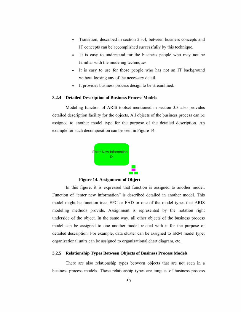
50
• Transition, described in section 2.3.4, between business concepts and
IT concepts can be accomplished successfully by this technique.
• It is easy to understand for the business people who may not be
familiar with the modeling techniques
• It is easy to use for those people who has not an IT background
without loosing any of the necessary detail.
• It provides business process design to be streamlined.
3.2.4 Detailed Description of Business Process Models
Modeling function of ARIS toolset mentioned in section 3.3 also provides
detailed description facility for the objects. All objects of the business process can be
assigned to another model type for the purpose of the detailed description. An
example for such decomposition can be seen in Figure 14.
Enter New InformationD
Figure 14. Assignment of Object
In this figure, it is expressed that function is assigned to another model.
Function of “enter new information” is described detailed in another model. This
model might be function tree, EPC or FAD or one of the model types that ARIS
modeling methods provide. Assignment is represented by the notation right
underside of the object. In the same way, all other objects of the business process
model can be assigned to one another model related with it for the purpose of
detailed description. For example, data cluster can be assigned to ERM model type;
organizational units can be assigned to organizational chart diagram, etc.
3.2.5 Relationship Types Between Objects of Business Process Models
There are also relationship types between objects that are not seen in a
business process models. These relationship types are tongues of business process

51
models. They talk together with objects representations to say what the model want
to describe. An object might have several relationship types with one another.
Relationship types can be assigned between objects during modeling in ARIS
Toolset. There are various relationships between objects that can be assigned to
objects in ARIS modeling tool. e.g. organizational unit may be technically
responsible for the execution of the function, or execute the function, or contributes
to function. We can see possible relationships that are provided by ARIS modeling
tool in Tables 12, 13, 14, 15, 16, and 17. As the control view represents all views on
own view by focusing on functions, it is preferred that only the relationships of other
views with function view are illustrated. These tables represent the relationships
from the point of view on the first column.
Table 12. Data-Function Relationships
Table 13. Function-Data Relationship
Relationship Type has output of
changes
archives
is archived by
deletes
Function View
(Function)
distributes
Data View (Cluster)
Relationship Type is input for
is approved during
Data View (Cluster)
is checked by
Function View
(Function)

52
Table 14. Function-Output Relationship
Table 15. Output-Function Relationship
Table 16. Function-Function Relationship
Relationship Type creates output to
Function View
(Function) produces
Output View (Document,folder,electr
onic document and
folder,)
Relationship Type provides input for
is used by
OutputView
(Document, folder,
electronic document
and folder,) is consumed by
Function View
(Function)
Relationship Type
Function View
(Application System)
can support
Function View
(Function)

53
Table 17. Organization-Function Relationships
To understand the business process models completely, we must understand
all relationships between the objects in a model. A mere graphical representation is
not enough to understand them; hence ARIS tool provides a reporting mechanism
that can address this challenge.
3.3 ARIS TOOLSET
Today business process modeling/analysis tools are increasingly used for
multiple reasons. In this thesis, comparison of business process modeling tools is not
considered. According to the Gartner Group30, as shown in Figure 15, ARIS toolset
is listed as the leader, under the vendor’s name, “IDS Scheer”, in business
analysis/modeling market. We used ARIS toolset in the phase of preparing a
technical contract of one project. This application is explained in Case Study,
Chapter 5. ARIS toolset supports all modeling views, methods and notations
described in sections 3.1. And 3.2.
30 http://www.gartner.com/gc/webletter/idsscheer/issue1/article1.html
Relationship Type is technically responsible for
executes
is it responsible for
decides on
contributes to
must inform about result of
must be informed about
must be informed about on
cancellation
Organization View
(Position, org.unit)
has consulting role in
Function View
(Function)

54
Figure 15. Modeling Tools
Beside its various functionalities, we used analysis/modeling and reporting
capabilities of ARIS toolset.
3.3.1 ARIS Toolset Reporting & Analysis
In addition to the graphical presentation of process analysis, ARIS toolset
also supports the output of these graphics with report wizard component. Results of
the business process models can be seen in these reports. Besides it’s various pre-
defined report scripts that are used to produce reports, the user can define new scripts
with a Script Editor. ARIS Script Editor is a component of ARIS toolset. It provides
all the functionality we need to create, edit and check scripts based upon ARIS Basic
Language Capability, such as report scripts. A script is a statement that contains
Visual Basic commands, as well as the commands from ARIS Basic Language
Capability. All objects and methods used in ARIS toolset can be found in [ARIS
Toolset Help Files].
Components in ARIS toolset access the scripts to make information available
to users from a database in the form of a table or text. Every component accesses a

55
particular type of script. The two first letters of the file extension identify the types of
scripts and third letter identify the context. For example, .RSM file extensions means
Report Script and the context is model oriented.
3.3.2 ModelHierarchy.rsm
Results delivered by predefined reports are much diverse. Some report scripts
give only function and organizational unit relationships of a process, some give all
objects type of the model and their names, whereas some of them give input/output
data that are allocated to each function of the process.
One of the pre-defined report scripts is ModelHierarchy.rsm. Function is the
foundation of analysis. Its results contain data about all views of a business process,
thus this report script produces output about the process from the point of control
view. Following are the contents of the results produced by this script.
• The report output analyzes the selected models, attributes and
available assignments of the function type.
• It gives all relations described in section 3.2.5, of objects of the
function type.
• The assigned models are further evaluated like the selected models up
to an adjustable structural depth
• Functions of the model selected to see its results can be arranged in
alphabetical order, or according to symbol type or its topology.
• The output is issued as text and includes tables for the model and
object information.
• Relationship types assigned according to other objects’ views during
modeling, described in section 3.2.5, are displayed in the report from
the point of function object view, e.g. data “is checked by” function
becomes function “checks” data.

56
CHAPTER 4
4 APPROACH
In this chapter, a unified approach that combines and integrates business
process modeling with functional requirements elicitation, based on ARIS modeling
and reporting methods, is described. This approach defines a requirements elicitation
process, which has three steps based on strategies and goals determined by the
customer:
Phase 1: AS-IS Study
Phase 2: TO-BE Study
Phase 3: Automated Functional Requirements Elicitation
4.1 STRATEGIC PLANNING
This phase must be accepted as precondition for our proposed approach.
There is no one right strategic planning model for all organizations and
circumstances. Every organization must have a strategic plan that describes their
vision, goals and directions to that vision that is strategies.
Before organizations start any process innovation activities supported by
technology, they must first develop or redevelop a strategic plan., and they must
make a connection between this plan and target business design, in the sense that
target business process design must be performed according to the strategic plan. It is
a manual task to link the strategies, which are based on business goals, which have to
be achieved to realize the vision, with target business processes, as currently there is
no comprehensive software tool to support these activities.
Target system functionalities that will be later derived as requirements from
this kind of study correspond to business processes or process activities that will
support our strategies.

57
Because every organization determines its own strategic plan and focus of
this thesis is not on strategic planning, strategic planning methods will not be
detailed in this section.
4.2 AS-IS STUDY
After strategic business planning is completed, “as-is” study is performed to
understand the current business processes and to provide outputs for to-be study by
describing existing business processes. Following are the activities of this phase:
• Gathering all resources related with business processes
• Organizing interview and JAD sessions
• Study of value added process chain
• Modeling of existing business processes during JAD sessions and
interview
• Approval of business process models
4.2.1 Gathering all resources related with business processes
Books, manuals, documents in which business processes and domain
knowledge exist and strategic business plan in which critical success factors and
business goals are clearly described, like master plan are gathered. Those resources
will help us in requirements elicitation process for many times, such as in describing
business processes and developing target conceptual and detailed design in the
direction of the business goals.
4.2.2 Organize interviews and JAD sessions
People who will be interviewed and who will attend JAD sessions are
determined. Schedule of these interviews and JAD sessions are also planned. Top
executives, domain experts, executives, project management, end user must attend
these activities. JAD sessions and interviews plan is produced at the end of this
activity.

58
4.2.3 Study of value added process chain
This study is the foundation for more detailed business process analysis. Key
business processes are determined. Further modeling activities are based on these
key business processes. After this phase, we obtain key business process diagrams.
4.2.4 Modeling of existing BP during JAD sessions and interviews
EEPC method of ARIS concept and ARIS toolset are used for business
process modeling. In ARIS toolset, EEPC-modeling option is selected for modeling.
Key business processes, all resources and JAD attendees’ opinions are used for
model developing.
Issues to be considered:
• Each sub process is examined and modeled individually.
• First of all, activities, their logical sequence and initial/result events
are determined and modeled.
• Then, for each activity (function), responsible entities and their roles
are assigned to the model.
• For each activity (function), information object including input/output
data is assigned to the model.
• Input/output and services for each activity (function) are assigned to
the model.
• The preview activities can be performed in parallel.
• If the business processes are not automated, that is, if data processing
is done manually and data storage is on physical environment,
physical document and folder objects can be used to represent the
information object of the data view. EEPC method supports these
notations.
• Feedback including change request taken at anytime is reflected to the
models.
• Models of existing business processes are the output of this phase.

59
4.2.5 Approval of business process models
The executives and project management must verify all business process
models created. Actually, this activity is performed during all steps of the “as-is”
study. Final approval of business process models must be received after modeling is
completed. The models can be modified based on corrections and/or changes in
business requirements. Approved existing business process models are the output of
“as-is” study and input for “to-be” study.
4.3 TO-BE STUDY
After completion of “as-is” study, “to-be” study is started to describe the IS
oriented target business processes. This study is very important for elicitation of
functional requirements. JAD sessions must be used for this step. Following are the
activities of this study:
• Determination of bottlenecks, IS-supported processing functions, new
business and information flows.
• Developing target design of business processes
• Approval of target business process models
4.3.1 Determination of bottlenecks, new business and information flows and
IS-supported processing functions
These three activities are performed synchronously as results of each one
affect the others.
• Bottlenecks that surfaced during “as-is” study are captured.
• Models of existing business processes are used for this activity.
• IS-supported processing functions are determined for each process
considering weaknesses, bottlenecks and deficiency of these
processes.
• According to these findings, new business and information flows are
determined.

60
• These determinations are parts of the target design of business
processes.
• When performing all these activities, strategic planning is taken into
account.
4.3.2 Developing target design of business processes
Completeness and correctness of functional requirements to be elicited are
closely related with this activity. EEPC is used for modeling target business
processes. Existing business process models are revisited from the beginning for
possible enhancements, and even redesign, considering strategic planning. For each
process following issues are considered.
• Control flow, that is logical sequence of process are modeled
considering IS-supported processing.
• Organizational units, input/output data, input/output and services are
assigned to each function. This can also be represented in Function
Allocation Diagram.
• Application systems that will support functions are also assigned to
each function.
• To obtain our preferred results at Step 3, that is functional
requirements of the target system, notations must be used correctly
with their semantics. Some of the usages of the notations are
controlled when modeling by built-in mechanisms of ARIS toolset.
Incorrect usages are not permitted. Some other semantic controls can
be performed using “Analysis” component of ARIS toolset.
• Notations of target business processes are different from the existing
business process, especially when information objects are considered.
• When modeling target system, for the purpose of completeness and
correctness of business process views, all essential object types of the
views, that must be used and their relationships that can/must be
assigned focusing on function in an EEPC are described below,

61
Table 18. Essential Object Types and Relationships
As stated in the table above, some relations are assigned automatically when
modeling with ARIS toolset. The user assigns remaining relations in the table
optionally. For clear and detailed model, we recommend that all relations be assigned
correctly.
VIEWS Object Types Relationships
Organization
View
Organizational
Unit, Position, Person
Type
External Person
is technically responsible for,
execute, is IT responsible for,
decides on, contributes to, must
inform about result of,
must be informed about, has
consulting role in, accepts
Function View
Application System
Type
can support
(Assigned automatically)
Input
Cluster
is approved during ,is input for, is
checked by
Data
View
Output
Cluster
changes, has output of, archives,
is archived by, deletes, distributes
Input
Document, Electronic
Document, Folder
Electronic Folder,
Telephone
provides input for
(assigned automatically)
Output
View
Output
Document, Electronic
document, Folder
Electronic Folder,
Telephone
creates output to
(Assigned automatically)

62
Some other issues that must be considered during business processes
modeling are:
• If a function is IS-supported and performed automatically, thus if
data that is retrieved from other IS, is recorded to the system
automatically after a determined time.
o “Application system”
o “Data cluster” both for data output and “electronic document”
for input or output must be assigned to this function.
• If a function is IS-supported and performed manually, thus if data,
that is output of another system, is entered by user to the system,
o “Document, “folder”, or “telephone” for input,
o “Data cluster” for data output as database
o “Application system” must be assigned to the function
• If data, that is stored in the system database, is used for obtaining
output manually,
o “Data cluster” for data input as system database
o “Document”, “folder” for output.
o “Application system” must be assigned to the function
• If data, that is stored in the system database, is used for sending data
to another IS or getting output manually in a digital environment.
o “Data cluster” for data input as system database
o “Electronic document” for output
o “Application system” must be assigned to the function
• If a function is not IS-supported, for both data input and data output
o “Document” and “folder” must be assigned for both input and
data output.
o Neither “Data cluster” nor “application system” be used.
• Output of this phase is target business process models.

63
4.3.3 Approval of target business process models
Final target business process models must be reviewed and approved by
executives and project management. The models can be modified based on
corrections and changes in business requirements through change management.
Approved target business process models are the output of the “to-be” study and
input for the automated functional requirements activity.
4.4 AUTOMATED FUNCTIONAL REQUIREMENTS ELICITATION
Target business process models are used for eliciting functional requirements
of the proposed system. They represent all business requirements and proposed
system requirements. Functional requirements of the proposed system are elicited by
using ARIS Toolset reporting mechanism. Model of automated functional
requirements elicitation is depicted in Figure 16.
TO-BE StudyCompleted
Eliciting FunctionalRequirements
Sys.Fuctional Requirementhas been generated
Target BusinessProcess Models
System FunctionalRequirements
Analysis Team
ARIS Reporting
System FunctionalRequirements
Report Template
Figure 16. Proposed Method for Functional Req. Elicitation

64
Extended version of Modelhierarchy.rsm, report script run by ARIS
Reporting Wizard helps us obtain functional requirements automatically from
business process models. Extended part of the Modelhierarchy.rsm, Aris Reporting
script, is given in Appendix C. Although there are many reports that can be generated
by ARIS Reporting Mechanism, as the focus is on deriving functional requirements
of the proposed system, we designed a report structure, as shown in Table 19, to
obtain the functional requirements and we generated it by using our extended script.
It is given in Appendix A. Functional requirements specifications generally include
five views of a function, namely data, function, organization, output and process
view. The first four views are considered as shown in Table 19. Process View, that is
logical sequence of the functions are also considered by stating start path, end path of
the process and preceding function for each function.
Table 19. Report Template Including All Aspect of Any Process
………………
Data View
………………
Output View
………………
Org.View
………………
Function
View
In this Report template;
• This table is repeated for every function of each process. Function
name appears at the top of the table.
• Logical sequence of the functions is considered.
• “Start path” and “End path” of the sequence are stated.
OBJECTS TYPE RELATIONSHIP OBJECT NAME
DATA INPUT
DATA OUTPUT
INPUT
OUTPUT
ORGANIZATIONAL
UNIT
APPLICATION
SYSTEM

65
• Preceding function for each function is stated with “by” expression
at the heading of the table. If no preceding function has been stated
for a function in the report, it means that this function is at the
beginning of the start path. Following function is stated with “leads
to” expression.
• “Relationships” column includes the relationships assigned during
modeling. They represent the relationships between objects and
function whose name appears at the top of the table.
• “Objects names” column includes the definitions written into the
symbols during modeling.
• Symbol types are given in the “object name” column with the object
names.
• Output of assigned model of each function is also produced according
to its detail level.
• A sample output of target business requirements based on the
template given in Table 19 is presented in Appendix A.

66
CHAPTER 5
5 AN APPLICATION
5.1 INTRODUCTION
In this chapter, an application of the approach proposed in Chapter 4 and
further study made after this application will be elaborated. This application was
performed during the period of technical specifications preparation phase of a IS
procurement project for the intelligence department of Turkish Land Forces
Command. Method proposed in Chapter 4 is partially applied in this project. We
performed all business process analysis activities using ARIS Toolset. In further
study, we developed a new reporting script by extending “Modelhieararchy.rsm”
reporting script of ARIS Toolset to generate functional requirements automatically,
although, the developed script was not utilized in the project due to time constraints,
the deadline for the delivery of the bidding documents.
Evaluation of the steps of the general process, benefits gained from practice
of proposed approach in Chapter 4 will be discussed in this chapter. For the sake of
secrecy, original inputs and outputs of the process will not be given. Namely,
business process models of intelligence and their reports, all specific resource names
used in project including people, tactical books, documents and department names
will not be detailed. Instead, we will describe the activities performed using process
modeling. Only one process model created during “to-be” study of the project will be
used as a typical example for EEPC and this model, given in Figure 25, will also be
used for the purpose of automated elicitation of functional requirements.
Requirement expressions elicited from this model manually at the time of technical
contract preparation will be compared with our requirements document that is
created automatically.

67
5.2 DEFINITIONS USED
Some important key terms and their meanings that will be used when explaining
application on proposed approach are given in Table 20.
Table.20. Definitions to be used
5.3 THE ROLES USED IN MODELS
All notations that can be used in typical business process by using ARIS
toolset are described in Chapter 3. Organizational charts, which specify the roles, are
given in Figures 17 and 18.
TLFCProject Office
TLFCProject Management
Executives
End Users
Domain Expert
Figure 17. Organizational Chart of TLFC Project Office
DEFINITIONS EXPLANATION
GENERAL
PROCESS
It includes all processes and implies automated
requirements elicitation process in which method
described in Chapter 4 is applied
STEPS It means sub processes of the general process.
EEPC
It describes each process from the point of all views, thus
control/process view.
FUNCTION TREE
It represents the activities of each sub process
hierarchically.
STAKEHOLDERS All participants of the general process.

68
METUProject Team
METUProject Management Analysis Team Network,HW
Team
Figure 18. Organizational Chart of METU Project Office
Following are the organizational units and their roles used in the models.
Table 21. Roles to be used in the Models
ORGANIZATIONAL
UNITS ROLES
TLFC PROJECT
OFFICE
It carries out the IS procurement project and consists of
TLFC Project management and externally involved
domain experts, executives, end users.
METU PROJECT
TEAM It counsels TLFC for preparing the technical contract.
ANALYSIS TEAM
It belongs to METU project team and analyzes the
business process to find out the system requirements that
are the foundation of technical contract.
DOMAIN EXPERT
It symbolizes all organizational units who have the
domain knowledge.
EXECUTIVES It symbolizes all executives of the end users.
END USER It symbolizes all the organizational units who will use
the system to be acquired or developed.

69
5.4 THE DEFINITIONS OF INPUTS AND OUTPUTS OF THE PROCESS
In business process models created by EEPC method, some input and output
objects are used to depict all kinds of inputs and outputs of the process. Their
explanations are given in Table 22.
Table.22. Input/Output to be used in the Models
INPUT/OUTPUT DEFINITIONS
RESOURCES
It includes books, documents, manuals, master plan
and strategic plan used in requirements elicitation
process.
KEY BUSINESS
PROCESS DIAGRAMS
It is the output of value added activity process chain
study and represents key processes. Key processes
were modeled by using ARIS’s EPC method.
EXISTING BUSINESS
PROCESS MODELS It includes all models developed during “as-is” study.
TARGET BUSINESS
PROCESS MODELS It includes all models produced during “to-be” study
VIEWS DATA
This logical model includes all data including function,
data, output and organization views of a process, which
is being studied on.
CHANGE REQUEST It includes all corrections, additions and deletions of
the TLFC office for the models.
FUNCTIONAL
REQUIREMENTS
It is both represented as physical document and data
cluster as this document is generated with the support
of automated tool, as per the format described in
Chapter 4.

70
5.5 PROCESS TO BE INVESTIGATED
Elicitation of functional requirements that are the main part of the technical
contract is the process to be investigated. First of all, general process is modeled by
EPC, and then this process is hierarchically decomposed into lower level process
steps to show the detailed activities of the process by using both EEPC and Function
Tree. In EEPC models all views of a process, namely data, function, output and
organization, are represented. In Function Trees, activities of the steps are
represented hierarchically.
5.5.1 Steps of the General Process
General process with its sub processes is given in Figure 19.
• Step 1: As-is Study
• Step 2: To-be Study
• Step 3: System Functional Requirements Elicitation
Strategic planning phase is not considered in this case study as the
responsible unit of the TLFC had already completed this phase and a document,
namely “master plan”, which had been approved by the management of the TLFC,
was given to the project team as the baseline document.
When applying proposed approach, “master plan” was used as a baseline
document for describing business processes. That is, current business processes and
target business process were described according to the organization goals.

71
Need for Determination of Target Sys.Func.
Req.has arised
As-is Study
To-be Study
System Functional Requirements Elicitation
Sys.Functional Requirementsare Elicited
As-is StudyCompleted
To-be StudyCompleted
Figure 19. Functional Requirements Elicitation Process

72
5.5.2 Evaluation of Step1
EEPC and function tree of “as-is” study are presented in Figures 20 and 21
respectively. In addition, a detailed description of “Modeling of Existing Business
Processes” is shown in Figure 22. Following are the lessons learned from this study.
• We had difficulty to commence the analysis with domain experts.
Complexity increased when describing and modeling current business
processes. Domain experts must have been involved in the business
process analysis from the very beginning.
• As there was no domain expert at the beginning, we spent a lot of time
in determining key processes. Before initiating the modeling of
business processes, key business processes must be determined.
Modeling without considering key business processes may lead to
increased complexity and it may lead to unnecessary time loss.
• Customer can better understand his own processes by performing “as-
is” study, with business process modeling. TLFC understood their
processes well and consequently their contributions to definition of
the requirements considerably increased.
• It is important for IT people to be involved in the business analysis,
because they can learn the business concepts and terminology that
will be necessary in transformation of business requirements into IT
requirements.
• Business process models are the platforms on which the stakeholders
can discuss and draw the conclusions. This enhances mutual
understanding.
• Modeling of existing business processes leads to modeling of to-be
processes. Thus, customer tends to describe the processes according to
the directives and instructions not according to the current state of the
processes. This situation contributes to increase in quality of the
processes and the transition of “as-is” study to the “to-be” study.

73
As-is Study
Gathering All ResourcesRelated with
BusinessProcess
Organizing Interview and JAD sessions
Study of Value Added Process Chain
Modeling of ExistingBusiness Processes During JAD sessions
and Interviews
Approval of Business Process Models
Figure 20. Function Tree of AS-IS Study

74
Need for AS-ISStudyHas Arisen
Gathering AllResources With
Business Processes
Existing BusinessProcess Models
Key BusinessProcess Diagrams
Organizing Interviewand JAD Sessions
Study of ValueAdded Process Chain
Modeling ExistingBusiness Process
During Jad Sessionsand Interviews
Approval of BusinessProcess Models
AS-IS StudyCompleted
ArisToolset
End User
Executives
ApprovedExisting BusinessProcess Models
Executives
JAD Sessionsand Interview Plan
Manuals,TacticalPublications,Master Plan
METUProject Team
TLFCProject Office
Domain Expert
TLFCProject Office
Domain Expert
Manuals,TacticalPublications,Master Plan
Manuals,TacticalPublications,Master Plan
Analysis Team
Figure 21. EEPC of AS-IS Study

75
Study of Value AddedProcess Chainis Completed
Determine the Activ.log.seq and
initial/result Eventsfor an ind. process
Modeling All these viewsin the same model
using eEPC
AS-IS StudyCompleted
ArisToolset
Existing BusinessProcess Models
Determine the Org.Units and their roles
for the Functions
Determine the Informationobject(input/output data)
for each Function
Determine the Physicalinput and output
Domain Expert
End User
Resources
Analysis Team
Views Data(function,data,
output,organization)
Analysis Team
Views Data(function,data,
output,organization)
Resources
Figure 22. Modeling of Existing Business Processes

76
5.5.3 Evaluation of Step 2
EEPC and function tree of “to-be” study are given in Figures 23 and 24
respectively. Following are the lessons from this study.
• “As-is” study provides considerable input for “to-be” study.
• Existing business process models can help the stakeholders to identify
the bottlenecks, deficiencies and the improvement points required in
the processes. Current process flows allowed TLFC to compare the
existing processes to the processes explained in the tactical
publications and instructions.
• “As-is” study and “to-be” study are performed together to some
extent, because bottlenecks, deficiencies and problems are already
captured in “as-is” study.
• Determination of IS supported functions, new information flows and
changes in existing workflows are the results of the “to-be” study.
• Target business process models were not finished completely due to
time constraint. An example for an incomplete business process
model “Intelligence Orientation”, created at the time of analysis
phase, is given in Figure 25.

77
To-be Study
Determination of bottlenecks
Determination ofBusiness and
Information flow(new,modified,deleted)
Determination of IS Supported Functions
Developing Target Design of
Business Process
Approval of Target Business Process Models
Figure 23. Function Tree of TO-BE Study

78
AS-IS StudyCompleted
Determination ofbottlenecks
TLFCProject Office
Change Request
Determination ofBusiness and
Information flow(new,modified,deleted)
Determination of ISSupported Functions
Approved ExistingBusiness Process Models
Domain Expert
Domain Expert
Analysis Team
Analysis TeamDeveloping TargetDesign of
Business Process
Approval of TargetBusiness Process Models
Executives
Target BusinessProcess Models
Approved TargetBusiness Process Models
ArisToolset
TO-BE StudyCompleted
Figure 24. EEPC of TO-BE Study

79
Request was takenfrom upper/sub/neighbour
units' Headquarters
Intelligence Request
Recording Requests
IntelligenceRequest
Company Noncommisionedofficer
Company Commander
ElicitingClear Information
Need(CIN)
ElicitingClear CommandRequest(CCR)
Table ofIntelligence Requests
Situation Map
Clear CommandRequest
CCR wasDetermined
CIN wasDetermined
Clear InformationNeed
Figure 25. Example for Incomplete BPM

80
• Some object types were not added to the models:
o Application system type
o Electronic document, folder
o Data cluster
• Actually, these object types are not very necessary in order to
manually elicit functional requirements of the software-intensive
system to be acquired or developed, for those people who have
enough software knowledge.
• We take a model created during contract preparation, given in Figure
25 and redeveloped it by adding required object types. New model of
the same business process can be seen in Figure 26. Some issues,
given in section 4.3.2 were considered when developing target
business model for the purpose of completeness and accuracy.

81
Request was takenfrom upper/sub/neighbour
units' HeadquartersAIntelligence Requests
L
Company IntelligenceInformation System
G Recording RequestsD
IntelligenceRequest
M
Company IntelligenceInformation System
G
Company Noncommisionedofficer
K
Company CommanderJ
ElicitingClear Information
Need(CIN)E
ElicitingClear CommandRequest(CCR)
F
CCR wasDetermined
C
CIN wasDetermined
B
IntelligenceRequests
P
Table of IntelligenceRequests
H
Situation MapI
CCRO
Company CommanderJ
CINN
CIN,CCR
Figure 26. Completed Target Business Process Model
5.5.4 Evaluation of Step 3
EEPC of last step of the general process is given in figure 27. Some results
and evaluations that are obtained from Step 3 experience are as follows:
• If we can have complete models for target business processes,
functional specifications do not have to be developed manually. There

82
is no need for the complete target business process models absolutely
to generate requirements manually.
• We generated functional requirements manually by examining and
evaluating the uncompleted “to-be” models. We used the information
gathered from users, domain expert and TLFC project management
during JAD sessions; and we used our software knowledge.
• Elicitation of functional requirements without tool support takes long
time.
• Reflection of business process changes in functional specifications is
a cumbersome task with risk of maintaining integrity.
• Requirements specifications generated during contract preparation
may lack control view. Thus, there is no indication of beginning and
end of the process. In other words, there is no initial and results
events.
• Completed target business process models can be used in automated
requirements elicitation by utilizing ARIS toolset reporting
mechanism.
• We used new target business process model that we developed, given
in Figure 26 to demonstrate how to elicit functional requirements
automatically.

83
TO-BE StudyCompleted
Eliciting FunctionalRequirements
Sys.Fuctional Requirementhas Determined
Target BusinessProcess Models
System FunctionalRequirements
Analysis Team
Figure 27. Step 3 Applied
As we see in Figure 27, there is no application software support, that is,
requirements had been generated manually by using target business process models.
5.6 REPORTING SCRIPT
The case study did not include the automated functional elicitation.
Functional requirements of the proposed system were determined manually due to
time constraints. We, however, later extended a script of ARIS Toolset and used it to
generate functional requirements from business process automatically.
5.6.1 Extended Reporting script- Newhierarchy.rsm
In ARIS toolset, Visual Basic and ARIS Basic Language Capability
commands are used for report and analysis scripts. All classes and methods can be
found in ARIS Toolset Help Files. We used Modelhierarchy.rsm report script of

84
ARIS Toolset as a basis. We have redeveloped tree procedures of the script and
created a function according to our needs, as given in Appendix B. Following are the
extensions applied in the new script.
• To create our own script, unique identifiers [Scheer, 2001] (numbers)
are assigned to model, object, relationship, symbol, and attribute types
of models. We used relationship numbers.
• Function isInSet (Index As Integer, TypeNum As Integer) As Boolean
is used to determine the object type whether it is in the index or not .
Index gets the numbers between 1-6 as follows:
1. Data Input
2. Data Output
3. Input
4. Output
5.Organizational Unit
6.Application System
• Index is searched according to the parameter, type number
“TypeNum”. Object types are all process views. Every object type has
a relationship types with other object type, described in Table 18, and
these relationship types have a type number.
• Sub OutFunction and Sub OutputModelData has been changed mostly
related with report format.
• Sub OutOfRelationships (oCxnOccs As Object, oCurrentFuncOcc As
Object) is developed according to our needs. “Function” object of the
model is called as parameter in this procedure. All of the stated
relationships are searched for each object type (1-6) and function
whether it exists or not. That is, all possible relationships of six object
types with the current function are searched for whether they exist or
not and if exist, they are displayed in the table with their names and
symbol types.
• When we run the script we are presented with three user-dialogs,
given in Appendix C. The first one includes determination of level

85
depth and graphic output request. The second one is for sorting
sequence for evaluating models, we must choose topologically option
in order to see the control flow of the process. Third one is model
types option; we must choose EEPC option.
5.6.2 Comparison and Evaluation of Outputs
In this section, requirements expressions obtained by using two techniques,
manually and automatically will be investigated. We used the model given in Figure
26 to automatically generate output as functional requirements document. This model
is target design of “intelligence orientation”. We created it by adding necessary
object types to the model given in 25. All of the business process models developed
at the time of contract preparation and functional requirements specifications
generated from these models can be found in “KEİS Model System Technical
Contract” at the intelligence department of TLFC. To give an example, requirements
expressions, for the first activity “recording request” of the process (intelligence
orientation), generated manually at the time of contract preparation are as follows:
Manually created output:
“Data on Intelligence Request that is taken from all units by written
document or verbally on telephone or wireless radio will be able to be entered to the
system. Data entered to the system must be recorded to the database, and data
recorded in the database must be able to be updated, reported, queried and deleted”.
“Data on Intelligence Request that is taken from all units by electronic form must be
buffered and saved after a determined time.”
If we generate requirements automatically for the same activity “recording
request”, of the same process (intelligence orientation), given in Figure 26,
requirements output would be as follows:

86
Automatically generated output:
1. 1. 1 Recording Requests
OBJECT TYPE RELATIONSHIPS OBJECT NAME
Data Input None None
Data Output has output of Table of Intelligence
Requests/Cluster
Input gets input from Intelligence Request
/Telephone
gets input from Intelligence
Requests/Document
gets input from Intelligence
Requests/Electronic
document
Output None None
Organizational Unit is under technical
responsibility of
Company
Commander/Position
is executed by Company
Noncommisioned
officer/Position
Application System can be supported by Company Intelligence
Information
System/Application
system type
Complete requirements output for the whole process is given in Appendix A.
As we see, there are some similarities and differences between two kinds of
expressions:

87
• Some process views, namely “data”, “function”, “output” views had
been considered in the manually created specifications.
“Organization” and “Control” views had not been considered.
• All of the process views can be seen in our proposed output.
Especially control view that represents process sequence is
considered.
• All of the requirements specifications can be seen in our proposed
output, but some expressions like: “Data entered to the system must
be recorded to the database, and data recorded in the database must be
able to be updated, reported, deleted and queried” and “by electronic
form must be buffered and saved after a determined time.” can not be
expressed directly but can be deduced from the table’s columns.
• In our proposed report template, symbol types of all objects are
displayed. If symbol of input object type is “electronic document”, we
can consider that “must be buffered and saved after a determined
time” expression can be used for this situation.
• If output data is exist as “cluster” in the table, “Cluster will be able to
be updated, reported, deleted and queried.” expression can also be
used for this situation.
• To make a comparison, we evaluated two types of requirements
expressions in quantitative approach. If we consider the process
“intelligence orientation”, there are 22 functional requirements
specifications developed manually at the time of contract preparation.
These can be found in “KEİS Model System Technical Contract”. 14
of them are related with standard expressions (reporting, deleting,
updating and querying) stated above. One of them is about
notification message. 7 of them are the specific (essential parts of the)
functional requirements.
• In our requirements report for the same process, given in Appendix A,
essential parts are obviously captured. Thus we covered %100 of the
essential parts of the manually generated specifications. If we assume

88
that other standard specifications can also be deduced from our report
generated via new script, it means that approximately %95 of the
overall functional requirements can captured.
As a result, requirements specification document that is obtained by using
modified script of ARIS CAPE Tool can be used as a baseline system functional
requirements document that all the stakeholders agree on, who participate analysis
activities.

89
CHAPTER 6
6 CONCLUSION
Within this study, a unified approach that combines and integrates business
process modeling with functional requirements elicitation, based on ARIS modeling
and reporting methods is proposed.
With a general literature review, requirements engineering, its challenges and
business–IT alignment concept are analyzed. Some requirements engineering
methods, like DFD modeling, object oriented modeling and formal methods are
briefly explained with its advantages and disadvantages. Business-IT alignment
process is discussed with three domains: Strategic planning, business process
analysis and design and IS architectures. Business process modeling concept is
investigated as a means of business analysis and design. IDEF0 process modeling
technique is also reviewed. After general review, ARIS approach is analyzed with its
integrated and complete architecture, modeling methods and tool. EEPC modeling
technique is explained with its advantages over other techniques. ARIS toolset that
supports “EEPC modeling” and “model reporting” that can be used for automated
requirements elicitation is also investigated.
Then, proposed approach for functional requirements elicitation is described.
Most of the steps of the proposed approach are applied to the TLFC project. In case
study, Chapter 5, proposed approach phase of this project, namely functional
requirements elicitation phase is explained. What we learned from this project and
what have been done after this project in terms of requirements generation are also
described in the case study. As a further study completed after TLFC project,
automated elicitation of functional requirements is examined based on ARIS toolset
reporting, as a phase of the proposed approach.

90
Information system is an important concept in which information technology
and business processes are integrated which other. If an organization will acquire a
new information system whether there exists an old one or not, it must determine the
requirements of the target system within the context of strategic planning, business
process analysis and design and complete IS architecture. Our proposed requirements
elicitation process helps the analyst to coordinate these three domains in order to
align IT with business. We however did not integrate strategic planning with
business process analysis and design. Our proposal takes strategic planning as pre-
condition. Formal integration of strategic planning into requirements elicitation has
already been proposed as future work, as we believe that strategic planning must be
related to business process analysis and design in any process innovation activities.
When determining requirements, process oriented approach rather than
function oriented approach help the organizations to see the big picture of the
system, thus they can organize around outcomes not the tasks. Processes are more
measurable than functions in terms that directly relate to organizational goals.
Proposed approach is based on process-oriented analysis.
Functional requirements elicitation must start with finding out the business
requirements. For this activity, business process modeling is an effective way. But
modeling tools and techniques must be customer-oriented rather than analyst-
oriented in order to better describe the business processes. These kinds of tools and
techniques also help JAD sessions in which customer and developer are trying to find
out the requirements of the target system. Proposed approach proposes a customer
oriented technique and tool, namely EEPC and ARIS toolset.
None of the CASE tools that were reviewed has the ability of business
process modeling tool in terms of finding out the business requirements. Manual
integration is necessary for these kinds of tools. Major deficiency of this type
integration is the transforming business requirements into the software intensive
system requirements. Our proposed approach can help customers or developers to
generate the functional requirements of any target system automatically. Both
customer and developer can formulate the system functional requirements easily on a
standard format that can be easily understood by all the stakeholders; and the

91
specification document obtained can be easily verified and modified by making
changes on the business process models. Functional requirements specification
generated by newhieararchy.rsm script can be used in IS acquisition. Developers can
use this specification as input to software requirements specification in software
development life cycle.
6.1 FUTURE WORK
Today, strategic planning is performed manually; there is no software tool
support that can assist in linking vision, goals and strategies, that is strategic
planning, with design of business processes. This challenge can be overcome by
integrating modeling of strategic planning with business process modeling. That
allows us to easily trace all functional requirements back to their related business
strategies and goals on which strategies are developed. This approach will, of
course, provide automation support for business-IT alignment.
Reporting script developed in this thesis can be further extended to generate
functional requirements, currently expressed in table form, by using natural
language.

92
REFERENCES
Anthes, G., 1994, "No More Creeps", Computer world, Vol. 48 Issue 18, pp. 107.
Avison, D., Fitzgerald, G., 1995, “Information System Development: Methodologies,
Techniques and Tools”, McGraw-Hill Book Company, England
Blessing, D., Österle, H., 1999, “Business Engineering Model”, Report of the
Institute for Information Management of the University of St. Gallen, St. Gallen.
Booch, G., 1994, “Object Oriented Analysis and Design with Applications, 2nd
Edition, Benjamin Cummings Pub., Redwood City, Calif.
Brinkkemper, S., 1990, “Formalization of Information Systems Modeling”, PhD
Thesis, University of Nijmegen, Amsterdam.
Christel, M., A., Kang, K., C., September 1992, “Issues in Requirements Elicitation”,
Software Engineering Institute, CMU/SEI-92-TR-12.
Cummins, F., A., 2002, “Enterprise Integration: An architecture for Enterprise
Application and Systems Integration”, John Wiley & Sons, Canada.
Davenport, H., T., 1993, “Process Innovation”, Harvard Business School Press,
Boston.
Dorfman, M., Thayer, R. H., 1997, “Software Requirements Engineering”, IEEE
Computer Society Press, Los Alamitos, Calif.

93
Engler, N., Nov 1996, “Bringing in the Users”, Computerworld, Vol 30 Issue 48, pp
3.
Goodrich, V., Olfman, L., January 1990, “An Experimental Evaluation of Task and
Methodology Variables for Requirements Definition Phase Success”, Proceedings of
the Twenty-Third Annual Hawaii International Conference on System Sciences, pp.
201-209, IEEE Computer Society.
Harrington, J.H., 1991, “Business Process Improvement”, McGraw-Hill, Newyork.
Halpin T. A., 1995, “Conceptual Schema and Relational Database Design” 2nd
Edition, Prentice-Hall.
Hammer, M., Cahmpy, J., 1993, “ Reengineering the Corporation. A manifesto for
Business Revolution”, Harper business, New York.
Hannam, R., 1997, “Computer Integrated Manufacturing: from concepts to
realisation”, Addison-Wesley, Harlow, England.
Jeffrey, A. Hoffer, Joey, F. George, Joseph, S. Valacich 1999 “Modern Systems
Analysis and Design” 2nd Edition, Addison-Wesley, Reading, Mass.
Keen, P., G., W., 1997, “ The Process Edge”, Boston, Harvard Business School
Press, Mass.
Kirchmer, M., 1999, “Business Process Oriented Implementation of Standard
Software”, Springer, Berlin, Newyork.
Kotonya, G., Sommerville, I., 1998, “Requirements Engineering: Process and
Techniques”, Sons&Wiley, New York.

94
Leffingwell, Dean., April 1997, “Calculating the Return on Investment from More
Effective Requirements Management”, Cutter IT Journal (formerly American
Programmer, Vol 10 No 4, pp.13-16)
Macaulay, L.A., “Requirements Engineering” Springer-Verlag London Limited,
London 1996
Marshall, C., 2000, “Enterprise Modeling with UML: Designing Successful Software
Through Business Analysis”, Addison-Wesley, Massachusetts.
Olle, T. W., Hagelstein, J., Macdonald, I.G., Rolland, C., Sol, H.G., Van Assche,
F.J.M. & Verrijn-Stuart, A.A., 1991, “Information System Methodologies: A
Framework for Understanding”, Addison-Wesley, Wokingham UK.
Pressman, R., S., 2001, “Software Engineering: a practitioner’s approach”, McGraw-
Hill, Newyork.
Sadoe, K., Corbitt, G., Boykin, R., 2001, “Enterprise Integration”, John Wiley &
Sons, Newyork.
Scheer, A., W., 1992, “Architecture of Integrated Information System-Foundations
of Enterprise-Modeling”, Springer, Berlin.
Scheer, A, W., 1994, “Business Process Engineering-Reference Models for Industrial
Enterprises”, 2nd Edition, Springer, Berlin.
Scheer, A., W., 1999, “ARIS-Business Process Frameworks”, Springer, Berlin.
Scheer, A, W , 2000, “ARIS-Business Process Modeling”, Springer, Berlin.
Scheer, A, W., September 2001, “Aris Help Files .pdf”, Saarbrücken, Germany.

95
Steele, P.M., 1999, “ Modeling Frameworks: The essential link between models and
methodologies”, Proc.10th Australasian Conference on Information Systems.
Whitmore, S., May 29, 1995, "Readers Shed Development Woes", PC Week, Vol 12
Issue 21, pp55.
Wiegers, K., 1999, “Software Requirements”, Microsoft Press.
William, U, 2001, “Business Driven IT Integration and Realignment”, Executive
Report, Vol. No.2, Business-IT Strategies Advisory Service, Cutter Consortium.
Yeates, D., Shields, M., Helmy, D., 1994, “System Analysis and Design eds.”,
Pitman Publishing, London.

96
APPENDIX A: OUTPUT OF NEWHIERARCHY.RSM SCRIPT
TARGET DESIGN OF 'INTELLIGENCE ORIENTATION' PROCESS
Start path
1. 1. 1 Recording Requests
OBJECT TYPE RELATIONSHIPS OBJECT NAME
Data Input none none
Data Output has output of Table of Intelligence
Requests/Cluster
Input gets input from Intelligence Requests
/Document
gets input from Intelligence Request
/Telephone
gets input from Intelligence Requests
/Electronic document
Output None none
Organizational Unit is executed by Company
Noncommisioned
officer /Position
is under technical
responsibility of
Company Commander
/Position
Application System can be supported by Company Intelligence
Information System
/Application system
type

97
1. 1. 2 Eliciting Clear Information Need(CIN)
by Function Recording Requests (Chapter 1. 1. 1)
OBJECT TYPE RELATIONSHIPS OBJECT NAME
Data Input has input of Table of Intelligence
Requests/Cluster
has input of Situation Map/Cluster
Data Output has output of CIN,CCR/Cluster
Input None none
Output Creates output to CIN /Electronic
document
Organizational Unit is executed by Company Commander
/Position
Application System can be supported by Company Intelligence
Information System
/Application system
type
End path
Start path
1. 1. 3 Eliciting Clear Command Request(CCR)
by Function Recording Requests D (Chapter 1. 1. 1)
OBJECT TYPE RELATIONSHIPS OBJECT NAME
Data Input has input of Table of Intelligence
Requests/Cluster
Data Output has output of CIN,CCR/Cluster
Input None none
Output creates output to CCR /Electronic
document

98
Organizational Unit is executed by Company Commander
/Position
Application System can be supported by Company Intelligence
Information System
/Application system
type
End path
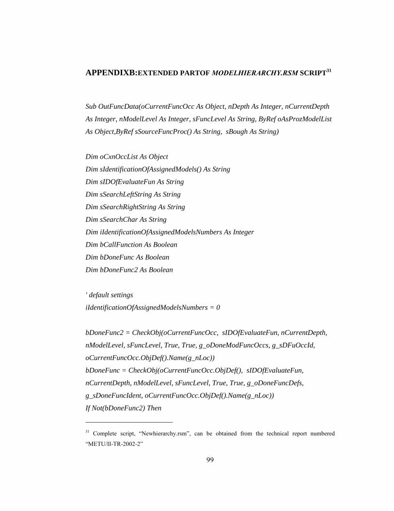
99
APPENDIXB:EXTENDED PARTOF MODELHIERARCHY.RSM SCRIPT31
Sub OutFuncData(oCurrentFuncOcc As Object, nDepth As Integer, nCurrentDepth
As Integer, nModelLevel As Integer, sFuncLevel As String, ByRef oAsProzModelList
As Object,ByRef sSourceFuncProc() As String, sBough As String)
Dim oCxnOccList As Object
Dim sIdentificationOfAssignedModels() As String
Dim sIDOfEvaluateFun As String
Dim sSearchLeftString As String
Dim sSearchRightString As String
Dim sSearchChar As String
Dim iIdentificationOfAssignedModelsNumbers As Integer
Dim bCallFunction As Boolean
Dim bDoneFunc As Boolean
Dim bDoneFunc2 As Boolean
' default settings
iIdentificationOfAssignedModelsNumbers = 0
bDoneFunc2 = CheckObj(oCurrentFuncOcc, sIDOfEvaluateFun, nCurrentDepth,
nModelLevel, sFuncLevel, True, True, g_oDoneModFuncOccs, g_sDFuOccId,
oCurrentFuncOcc.ObjDef().Name(g_nLoc))
bDoneFunc = CheckObj(oCurrentFuncOcc.ObjDef(), sIDOfEvaluateFun,
nCurrentDepth, nModelLevel, sFuncLevel, True, True, g_oDoneFuncDefs,
g_sDoneFuncIdent, oCurrentFuncOcc.ObjDef().Name(g_nLoc))
If Not(bDoneFunc2) Then
31 Complete script, “Newhierarchy.rsm”, can be obtained from the technical report numbered
“METU/II-TR-2002-2”

100
sSearchChar = Chr$(9)
sSearchLeftString = ""
sSearchRightString = ""
bCallFunction = False
If nCurrentDepth <= nDepth Then
If Not (oCurrentFuncOcc.SymbolNum() = ST_PRCS_IF) Then
AssignedModelsIntoList oCurrentFuncOcc, nDepth,
nCurrentDepth, nModelLeveL, sFuncLevel, oAsProzModelList, sSourceFuncProc
End If
End If
If bDoneFunc = False Then
g_oOutFile.OutputLnF(Str$(nCurrentDepth)+"."+Str$(nModelLevel)+"."+s
FuncLevel+" "+ oCurrentFuncOcc.ObjDef().Name(g_nLoc),"REPORT3")
If g_sSelecttion = "EEPC" And Not(sBough = "") Then
g_oOutFile.OutputLnF("by " & sBough,"REPORT3")
End If
If g_bDoneFunc = True Then
StringCut g_sDoneFuncID, sSearchLeftString,
sSearchRightString, sSearchChar
g_oOutFile.OutputLnF("leads to " & " function " +
sSearchRightString +" (Chapter " + sSearchLeftString+")","REPORT3")
End If
g_oOutFile.BeginTable(100,C_BLACK,COLOR_TRANSPARENT,FMT_LEF
T,0)
Set oCxnOccList = oCurrentFuncOcc.CxnOccList()
If oCxnOccList.Count() > 0 Then
OutOfRelationships oCxnOccList, oCurrentFuncOcc
End If

101
OutOfAssignedModels oCurrentFuncOcc, oAsProzModelList,
nDepth, nCurrentDepth, nModelLevel
g_oOutFile.EndTable("",100, "Times New
Roman",12,C_BLACK,COLOR_TRANSPARENT,0,FMT_LEFT Or FMT_VTOP,0)
Else
StringCut sIDOfEvaluateFun, sSearchLeftString, sSearchRightString,
sSearchChar
g_oOutFile.OutputLnF(Str$(nCurrentDepth)+"."+Str$(nModelLevel)+"."+s
FuncLevel+ " " + sSearchRightString +" See " + sSearchLeftString,"REPORT3")
g_oOutFile.BeginTable(100,C_BLACK,COLOR_TRANSPARENT,FMT_LEF
T,0)
Set oCxnOccList = oCurrentFuncOcc.CxnOccList()
If oCxnOccList.Count() > 0 Then
OutOfRelationships oCxnOccList, oCurrentFuncOcc
End If
g_oOutFile.EndTable("",100, "Times New
Roman",12,C_BLACK,COLOR_TRANSPARENT,0,FMT_LEFT Or FMT_VTOP,0)
End If
End If
End Sub
------------------------------------
Function isInSet(Index As Integer, TypeNum As Integer) As Boolean
isInSet = False
Select Case Index
Case 1

102
If (TypeNum=49) Or (TypeNum=222) Or (TypeNum=223)
Then isInSet = True
Case 2
If (TypeNum=50) Or (TypeNum=224) Or (TypeNum=225) Or
(TypeNum=226) Or (TypeNum=227) Or (TypeNum=228) Then isInSet = True
Case 3
If (TypeNum=53) Then isInSet = True
Case 4
If (TypeNum=28) Then isInSet = True
Case 5
If (TypeNum=65) Or (TypeNum=435) Or (TypeNum=10) Or
(TypeNum=148) Or (TypeNum=232) Or (TypeNum=233) Or (TypeNum=255) Or
(TypeNum=266) Or (TypeNum=316) Or (TypeNum=355) Then isInSet = True
Case 6
If (TypeNum=221) Then isInSet = True
End Select
End Function
----------------------------------------
Sub OutOfRelationships(oCxnOccs As Object, oCurrentFuncOcc As Object)
Dim oCurrentCxnOcc As Object
Dim oAssignedModels As Object
Dim oSubModFunc As Object
Dim sCurrentFuName As String
Dim sOutStr As String
Dim sObjName As String
Dim ObjectsType(6)
Dim ObjectsExist(6)
Dim ObjectTypeStr As String
Dim UseAssigned As Boolean

103
Dim n As Integer
ObjectsType(1)="Data Input "
ObjectsType(2)="Data Output"
ObjectsType(3)="Input"
ObjectsType(4)="Output"
ObjectsType(5)="Organizational Unit"
ObjectsType(6)="Application System"
g_oOutFile.TableRow()
g_oOutFile.TableCell("OBJECT TYPE",30, "Times New
Roman",12,C_BLACK,COLOR_TRANSPARENT,0,FMT_LEFT Or FMT_VTOP,0)
g_oOutFile.TableCell("RELATIONSHIPS",30, "Times New
Roman",12,C_BLACK,COLOR_TRANSPARENT,0,FMT_LEFT Or FMT_VTOP,0)
g_oOutFile.TableCell("OBJECT NAME",40, "Times New
Roman",12,C_BLACK,COLOR_TRANSPARENT,0,FMT_LEFT Or FMT_VTOP,0)
For n=1 To 6
ObjectTypeStr = ObjectsType(n)
ObjectsExist(n) = False
sCurrentFuName = oCurrentFuncOcc.ObjDef().Name(g_nLoc)
For i = 0 To oCxnOccs.Count()-1
Set oCurrentCxnOcc = oCxnOccs.Get(i)
If
oCurrentFuncOcc.IsEqual(oCurrentCxnOcc.SourceObjOcc()) = True Then
If isInSet(n, oCurrentCxnOcc.Cxn().TypeNum()) Then
g_oOutFile.TableRow()

104
g_oOutFile.TableCell(ObjectTypeStr,30,
"Times New Roman",12,C_BLACK,COLOR_TRANSPARENT,0,FMT_LEFT Or
FMT_VTOP,0)
ObjectTypeStr = ""
sObjName = ""
sObjName =
oCurrentCxnOcc.TargetObjOcc().SymbolName()
g_oOutFile.TableCell(oCurrentCxnOcc.Cxn().ActiveType(),30, "Times New
Roman",12,C_BLACK,COLOR_TRANSPARENT,0,FMT_LEFT Or FMT_VTOP,0)
sOutStr =
oCurrentCxnOcc.TargetObjOcc().ObjDef().Name(g_nLoc)
If sOutStr = "" Then sOutStr = "without
Namen"
g_oOutFile.TableCell(sOutStr+"/"+sObjName,40, "Times New
Roman",12,C_BLACK,COLOR_TRANSPARENT,0,FMT_LEFT Or FMT_VTOP,0)
ObjectsExist(n) = True
End If
Else
If isInSet(n, oCurrentCxnOcc.Cxn().TypeNum()) Then
g_oOutFile.TableRow()
g_oOutFile.TableCell(ObjectTypeStr,30,
"Times New Roman",12,C_BLACK,COLOR_TRANSPARENT,0,FMT_LEFT Or
FMT_VTOP,0)
ObjectTypeStr = ""
sObjName = ""
sObjName =
oCurrentCxnOcc.SourceObjOcc().SymbolName()

105
g_oOutFile.TableCell(oCurrentCxnOcc.Cxn().PassiveType(),30, "Times New
Roman",12,C_BLACK,COLOR_TRANSPARENT,0,FMT_LEFT Or FMT_VTOP,0)
sOutStr =
oCurrentCxnOcc.SourceObjOcc().ObjDef().Name(g_nLoc)
If sOutStr = "" Then sOutStr = "without
Namen"
g_oOutFile.TableCell(sOutStr+"/"+sObjName,40, "Times New
Roman",12,C_BLACK,COLOR_TRANSPARENT,0,FMT_LEFT Or FMT_VTOP,0)
ObjectsExist(n) = True
End If
End If
Set oCurrentCxnOcc = Nothing
Next i
If (ObjectTypeStr <> "") Then
g_oOutFile.TableRow()
g_oOutFile.TableCell(ObjectTypeStr,30, "Times New
Roman",12,C_BLACK,COLOR_TRANSPARENT,0,FMT_LEFT Or FMT_VTOP,0)
g_oOutFile.TableCell("none",30, "Times New
Roman",12,C_BLACK,COLOR_TRANSPARENT,0,FMT_LEFT Or FMT_VTOP,0)
g_oOutFile.TableCell("none",40, "Times New
Roman",12,C_BLACK,COLOR_TRANSPARENT,0,FMT_LEFT Or FMT_VTOP,0)
ObjectTypeStr = ""
End If
ObjectTypeStr = ObjectsType(n)
Set oAssignedModels =
oCurrentFuncOcc.ObjDef().AssignedModels()

106
If (oAssignedModels.Count() > 0) Then
UseAssigned = False
For h = 0 To oAssignedModels.Count()-1
If isInSet(n,
oAssignedModels.Get(h).TypeNum()) Then UseAssigned = True
Next
Else
UseAssigned = False
End If
If UseAssigned = True Then
g_oOutFile.OutputLn("", "Times New
Roman",8,C_BLACK,COLOR_TRANSPARENT,FMT_LEFT,0)
g_oOutFile.TableRow()
g_oOutFile.TableCell("OBJECT TYPE",30, "Times New
Roman",12,C_BLACK,COLOR_TRANSPARENT,0,FMT_LEFT Or FMT_VTOP,0)
g_oOutFile.TableCell("RELATIONSHIPS",30, "Times New
Roman",12,C_BLACK,COLOR_TRANSPARENT,0,FMT_LEFT Or FMT_VTOP,0)
g_oOutFile.TableCell("OBJECT NAME",40, "Times New
Roman",12,C_BLACK,COLOR_TRANSPARENT,0,FMT_LEFT Or FMT_VTOP,0)
For h = 0 To oAssignedModels.Count()-1
Select Case oAssignedModels.Get(h).TypeNum()
Case MT_FUNC_ALLOC_DGM
'Funktionszuordnungsdiagramm
Set oSubModFunc =
oAssignedModels.Get(h).ObjOccListFilter(sCurrentFuName, OT_FUNC, g_nLoc)

107
Set oCxnOccs =
oAssignedModels.Get(h).CxnOccList()
For i = 0 To oCxnOccs.Count()-1
Set oCurrentCxnOcc =
oCxnOccs.Get(i)
If isInSet(n,
oAssignedModels.Get(h).TypeNum()) Then
g_oOutFile.TableRow()
If
oSubModFunc.Get(0).IsEqual(oCurrentCxnOcc.SourceObjOcc().ObjDef()) = True
Then
g_oOutFile.TableCell(ObjectTypeStr,30, "Times New
Roman",12,C_BLACK,COLOR_TRANSPARENT,0,FMT_LEFT Or FMT_VTOP,0)
ObjectTypeStr=""
g_oOutFile.TableCell(oCurrentCxnOcc.Cxn().ActiveType(),30, "Times New
Roman",12,C_BLACK,COLOR_TRANSPARENT,0,FMT_LEFT Or FMT_VTOP,0)
g_oOutFile.TableCell(oCurrentCxnOcc.TargetObjOcc().ObjDef().Name(g_n
Loc),40, "Times New Roman",12,C_BLACK,COLOR_TRANSPARENT,0,FMT_LEFT
Or FMT_VTOP,0)
Else
g_oOutFile.TableCell(ObjectTypeStr,30, "Times New
Roman",12,C_BLACK,COLOR_TRANSPARENT,0,FMT_LEFT Or FMT_VTOP,0)
ObjectTypeStr=""

108
g_oOutFile.TableCell(oCurrentCxnOcc.Cxn().PassiveType(),30, "Times New
Roman",12,C_BLACK,COLOR_TRANSPARENT,0,FMT_LEFT Or FMT_VTOP,0)
g_oOutFile.TableCell(oCurrentCxnOcc.SourceObjOcc().ObjDef().Name(g_n
Loc),40, "Times New Roman",12,C_BLACK,COLOR_TRANSPARENT,0,FMT_LEFT
Or FMT_VTOP,0)
End If
End If
Set oCurrentCxnOcc = Nothing
Next i
End Select
Next h
If (ObjectTypeStr <> "") Then
g_oOutFile.TableRow()
g_oOutFile.TableCell(ObjectTypeStr,30, "Times New
Roman",12,C_BLACK,COLOR_TRANSPARENT,0,FMT_LEFT Or FMT_VTOP,0)
g_oOutFile.TableCell("none",30, "Times New
Roman",12,C_BLACK,COLOR_TRANSPARENT,0,FMT_LEFT Or FMT_VTOP,0)
g_oOutFile.TableCell("none",40, "Times New
Roman",12,C_BLACK,COLOR_TRANSPARENT,0,FMT_LEFT Or FMT_VTOP,0)
ObjectTypeStr = ""
End If
End If
Next
Set oCurrentCxnOcc = Nothing
Set oAssignedModels = Nothing

109
Set oSubModFunc = Nothing
End Sub
-----------------------------------------------
Sub OutputModelData(oCurrentModel As Object, nCurrentDepth As Integer,
nModelLevel As Integer,sSourceFunc As String, bFirstModel As Boolean)
Dim oSuperiorObjectList As Object
Dim oCurrentSuperiorObject As Object
Dim sOutString As String
Dim nModelZoom As Double
Dim bFirst As Boolean
Dim bDummy As Boolean
Set oSuperiorObjectList = CreateObject("ARIS.ObjDefList.6.0")
bFirst = True
If bFirstModel = True Then
If nCurrentDepth > 1 Then
g_oOutFile.OutputLnF(Str$(nCurrentDepth)+".Level","REPORT1")
End If
g_oOutFile.OutputLn("", "Times New
Roman",8,C_BLACK,COLOR_TRANSPARENT,FMT_LEFT,0)
g_oOutFile.OutputLn("TARGET DESIGN OF '" &
oCurrentModel.Name(g_nLoc)+"' PROCESS ","Times New
Roman",14,C_BLACK,COLOR_TRANSPARENT,FMT_CENTER,0)
g_oOutFile.OutputLn("", "Times New
Roman",8,C_BLACK,COLOR_TRANSPARENT,FMT_LEFT,0)
End Sub

110
APPENDIX C: USER DIALOGS

111