Embed Size (px)
Citation preview

An Application-Specific Protocol Architecture for Wireless
Microsensor Networks
Wendi HeinzelmanAnantha Chandrakasan and Hari Balakrishnan
Massachusetts Institute of Technology
Microsensor Networks
• Remote monitoring of the environment– Surveillance– Machine diagnostics
• Relevant parameters:– System lifetime (energy efficiency)– Quality– Latency
Base station
A
B D
E
f(A-G)C
FG
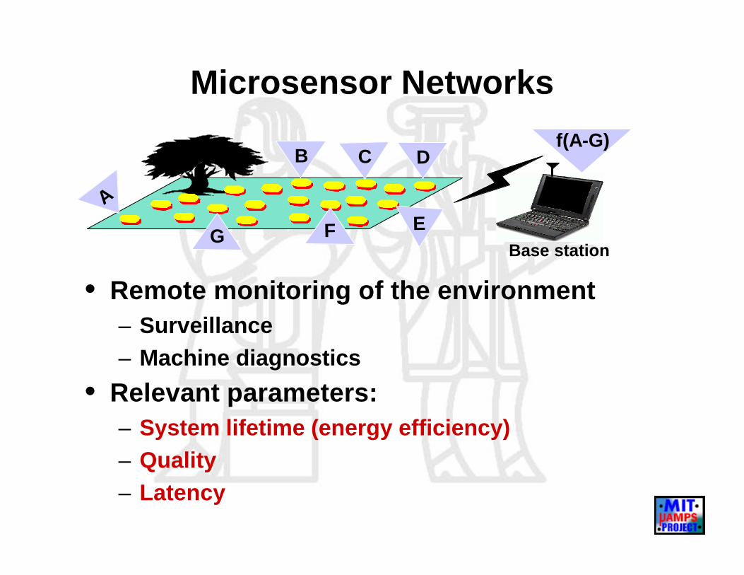
The MIT µ-AMPS Project
• Develop energy-optimized solutions – Node architecture and radio hardware– OS, algorithms and protocols
• Assumptions:– Base station far from nodes– All nodes energy-constrained– Locally, data correlated
Goal: Design protocols for high quality and energy and spectrum efficiency
ApplicationTransportNetwork
Physical
MACData-link
Application-SpecificArchitecture

General-Purpose Protocol Architectures
• Direct transmission– Power scales as Rn
– Bandwidth limitations
• Routing– MTE (Min. Trans. Energy) Routing– Multi-step communication– Short lifetimes for close nodes
• Clustering– Cellular model– Needs high-energy cluster-head
A�B�C if:dAB
2+dBC2<dAC
2
AB C
R

LEACH: Energy-Efficient Protocol Architecture
• Low-Energy Adaptive Clustering Hierarchy– Adaptive, self-configuring cluster formation– Localized control for data transfers– Low-energy medium access– Application-specific data aggregation
Base station
Cluster-head

Dynamic Clusters
• Cluster-head rotation to evenly distribute energy load• Adaptive clusters
– Clusters formed during set-up– Scheduled data transfers during steady-state
Time•••
START START START
Set-up Frame RoundSteady-state
Cluster-heads = •
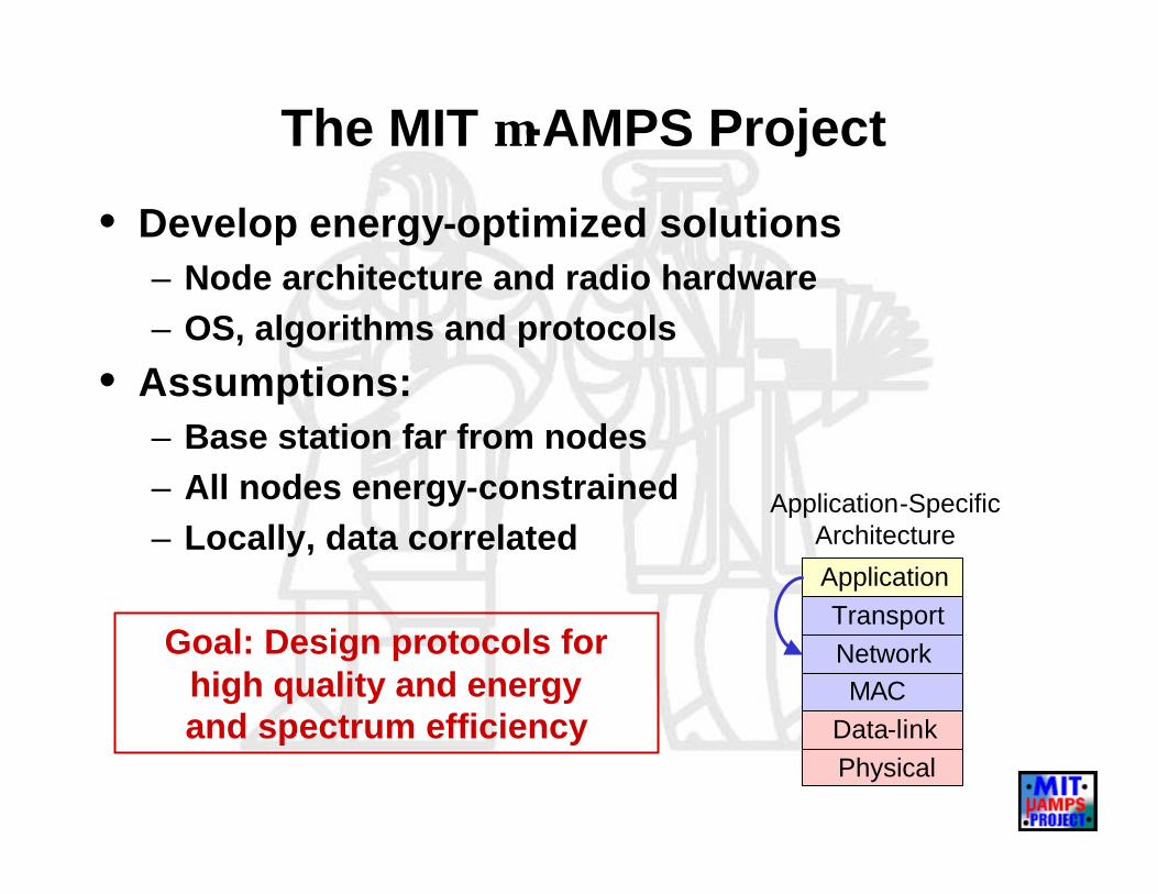
Distributed Cluster Formation Algorithm
Using Pi(t)
Choose CH with “loudest” announcement
Cluster-headNodes
Non-CHNodes
Node icluster-head ?Yes No
Wait forcluster-head
announcements
Send Join-Requestmessage to chosen
cluster-head
Announcecluster-head status
Wait forJoin-Request
messages
Steady-stateoperation for
t=Tround seconds
Autonomous decisions lead to global behavior
• No global control• Flexible, fault-tolerant

Distributed Cluster Formation
ktN
i
=∗= ∑=
1)(P CH] E[#1
i
Ci(t) = 1 if node i a CH in last r rounds
• Assume nodes begin with equal energy• Design for k clusters per round• Want to evenly distribute energy load a Each node CH once in N/k rounds
−=0
)/mod(* )(Pi kNrkNk
t0 )(Ci =t
1 )(Ci =t
k = system param.(Analytical optimum)
• Can determine Pi(t) with unequal node energy

Unequal Initial Energies
High-energy nodes CH more often than low-energy nodes
ktE
tEt
total
i
)()(
)(Pi = Ei(t) = energy of node i at time tEtotal(t) = total energy in system at time t
Cluster-head nodesEi(t) ≈ Eo – X
Pi(t) ≈ 0
Non-cluster-head nodesEi(t) ≈ Eo
Pi(t) ≈ k/(N-kr)
If nodes begin with Eo
Etotal ≈ Eo(N-kr) + (Eo-X)kr
Set-up Steady-state
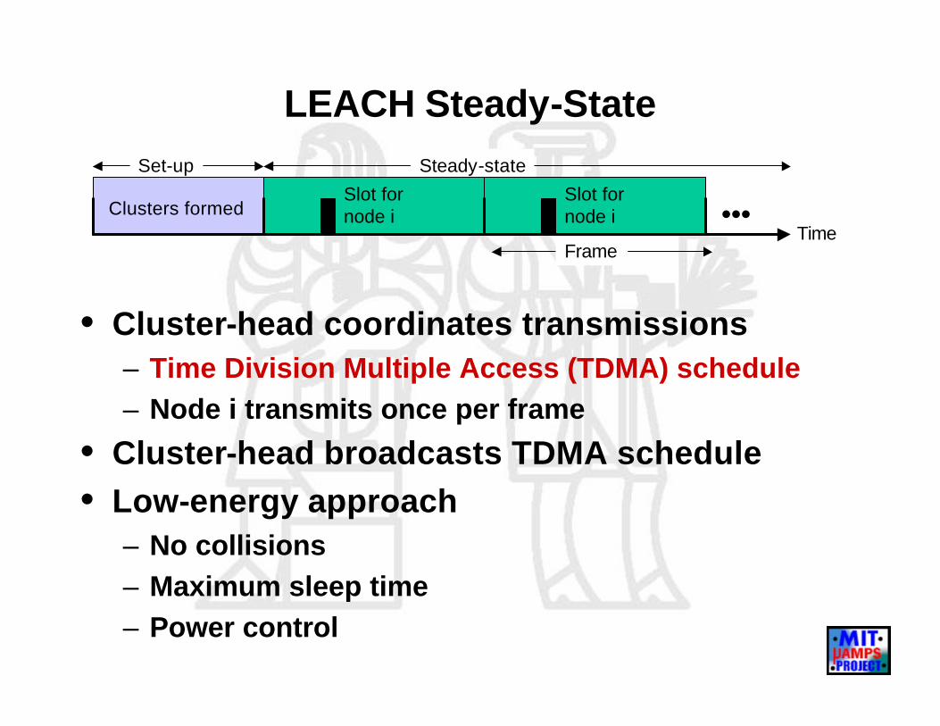
LEACH Steady-State
• Cluster-head coordinates transmissions– Time Division Multiple Access (TDMA) schedule– Node i transmits once per frame
• Cluster-head broadcasts TDMA schedule • Low-energy approach
– No collisions– Maximum sleep time– Power control
Clusters formedTime
Slot for node i
Slot for node i •••Frame

Inter-Cluster Interference
• Transmission in different clusters can collide– Nodes minimize transmission power– Each cluster has unique spreading code – Distributed solution to minimize interference
BA
C
Cluster B
Cluster C

LEACH Medium Access
ADV• CSMA
• Large power, small messages
ADV Join-REQ SCHTime
Steady-stateSet-up
Join-REQ• CSMA
• Large power, small messages
SCH• DS-SS code
• Power to reach all members
CH CHNon-CH
Data Transfer to Cluster-Head• TDMA slot (with DS-SS)
• Power to reach CH, large messages

Application-Specific Data Aggregation
• Clusters exhibit spatial locality– Local data aggregation– Common signal enhanced/noise reduced
• Computation vs. communication tradeoff– Depends on cost of computation and communication– Signal processing within the network
Energy for beamforming (J/bit/signal)
Tot
al e
nerg
y (J
)No DataAggregation
Local Data Aggregation
**
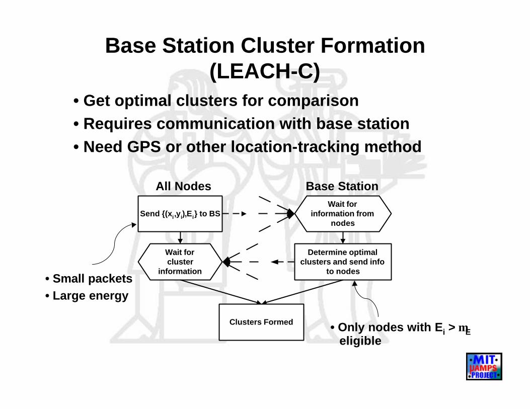
Base Station Cluster Formation (LEACH-C)
All Nodes Base Station
• Only nodes with Ei > µEeligible
• Get optimal clusters for comparison• Requires communication with base station• Need GPS or other location-tracking method
• Small packets• Large energy
Wait forinformation from
nodes
Determine optimalclusters and send info
to nodes
Send {(xi,yi),Ei} to BS
Wait forcluster
information
Clusters Formed

Simulation Framework
• Extensions to ns network simulator– Computation and communication energy models
• Radio energy
• StrongARM processor beamforming [A. Wang]
– New node states– Medium access– LEACH, LEACH-C, MTE routing, static clustering
Transceiver Tx Amplifier Transceiver
Eelec* kk bit packet εamp* k * d2 Eelec* k
d
Transmitter Receiver
k bit packet
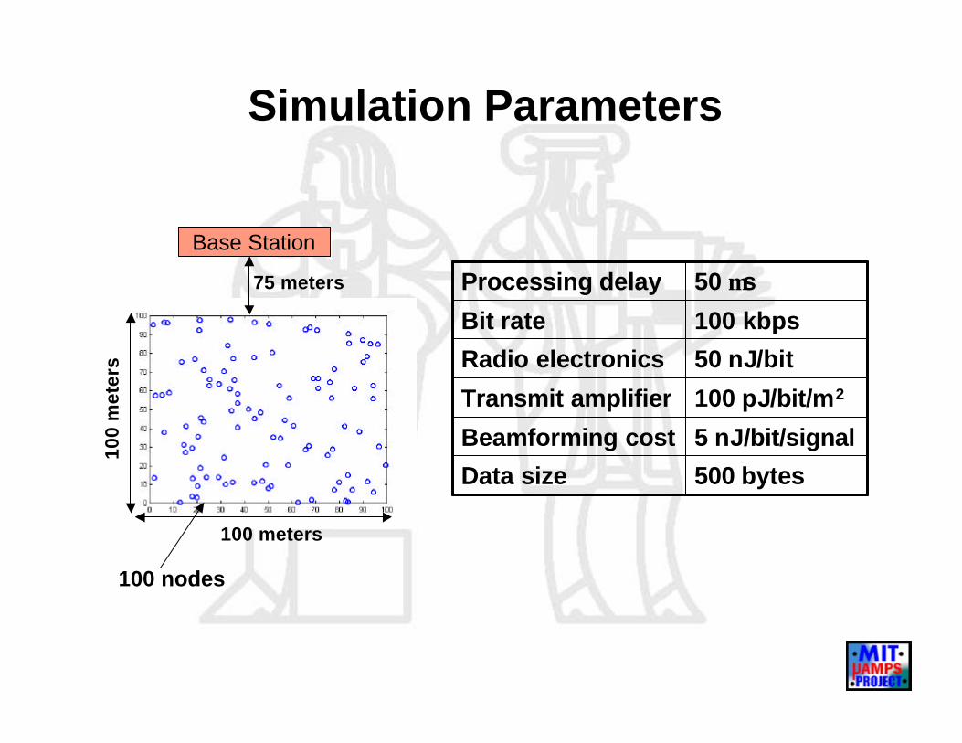
Simulation Parameters
500 bytesData size
5 nJ/bit/signalBeamforming cost
100 pJ/bit/m2Transmit amplifier
50 nJ/bitRadio electronics
100 kbpsBit rate
50 µsProcessing delay
Base Station
75 meters
100
met
ers
100 meters
100 nodes
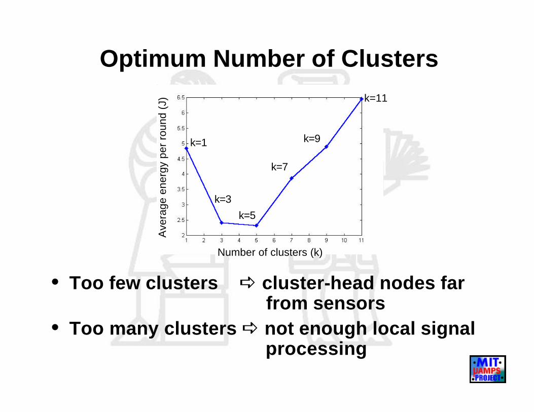
Optimum Number of Clusters
Ave
rage
ene
rgy
per
roun
d (J
)
Number of clusters (k)
k=7
k=9
k=5
k=3
k=1
k=11
• Too few clusters a cluster-head nodes far from sensors
• Too many clusters a not enough local signal processing
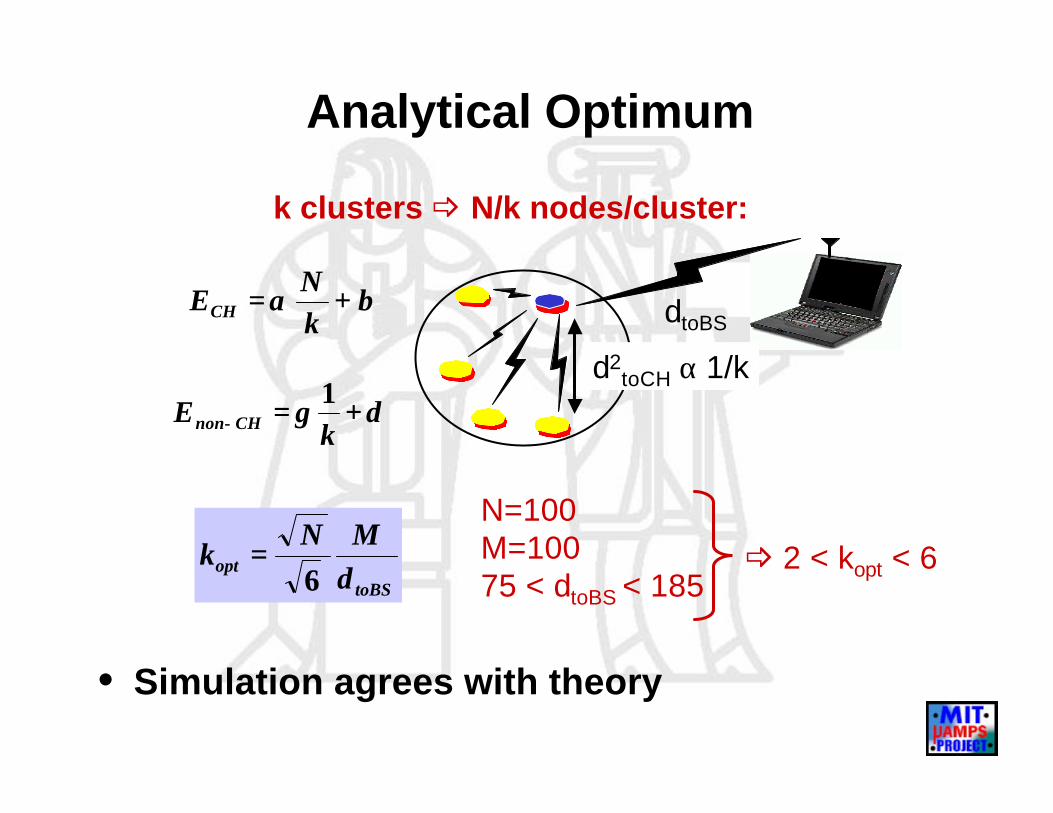
Analytical Optimum
δγ +=− kE CHnon
1
k clusters _ N/k nodes/cluster:
toBSopt d
MNk
6=
N=100M=10075 < dtoBS < 185
_ 2 < kopt < 6
• Simulation agrees with theory
βα +=kN
ECH dtoBS
d2toCH α 1/k
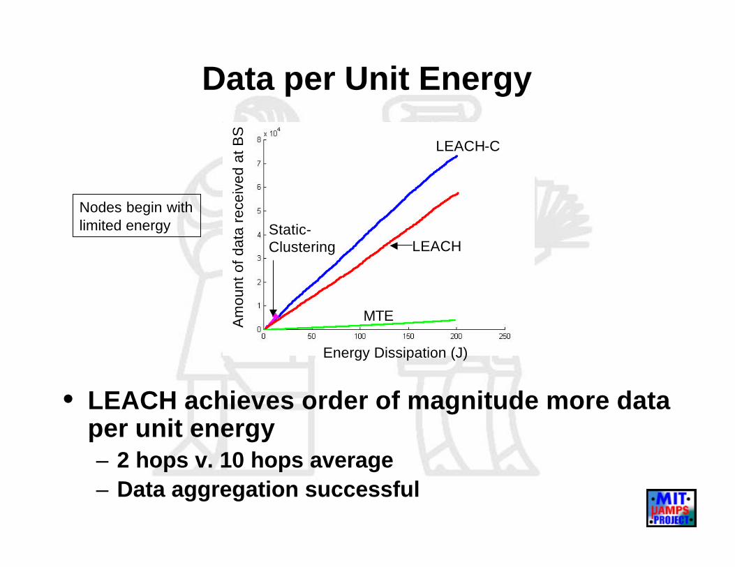
Data per Unit Energy
Am
ount
of d
ata
rece
ived
at B
S
Energy Dissipation (J)
Static-Clustering
LEACH-C
LEACH
MTE
• LEACH achieves order of magnitude more data per unit energy – 2 hops v. 10 hops average– Data aggregation successful
Nodes begin withlimited energy
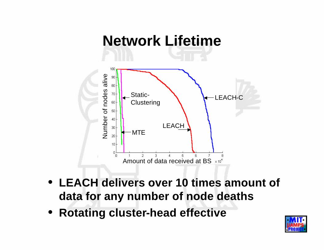
Network Lifetime
Num
ber
of n
odes
aliv
e
Amount of data received at BS
Static-Clustering
LEACH-C
LEACHMTE
• LEACH delivers over 10 times amount of data for any number of node deaths
• Rotating cluster-head effective

Summary
• Microsensor network protocols must be designed for– Bandwidth efficiency– Energy efficiency– High quality
• Application-specific protocol architecture beneficial – Most efficient use of limited resources– Ideas extendable to other application spaces