Embed Size (px)
Citation preview

Hindawi Publishing CorporationMathematical Problems in EngineeringVolume 2011, Article ID 783094, 18 pagesdoi:10.1155/2011/783094
Research ArticleAn Application of Saint Venant’s Theory toVolterra’s Distortions
Ivana Bochicchio,1 Ettore Laserra,1 and Massimo Pecoraro2
1 Dipartimento di Matematica e Informatica, Universita di Salerno, Via Ponte Don Melillo,I-84084 Fisciano (SA), Italy
2 Dipartimento di Ingegneria dell’Informazione e Matematica Applicata, Universita di Salerno,Via Ponte Don Melillo, 84084 Fisciano (SA), Italy
Correspondence should be addressed to Ivana Bochicchio, [email protected]
Received 18 November 2010; Accepted 4 December 2010
Academic Editor: Ezzat G. Bakhoum
Copyright q 2011 Ivana Bochicchio et al. This is an open access article distributed under theCreative Commons Attribution License, which permits unrestricted use, distribution, andreproduction in any medium, provided the original work is properly cited.
This paper deals with the analysis of the sixth elementary Volterra’s distortion for a circular hollow,homogeneous, elastic, isotropic cylinder. More precisely, the specific load connected to the sixthdistortion is proved to be equivalent (in Saint Venant’s theory) to a right combined compressiveand bending stress and to a right combined tensile and bending stress. Our results have beenapplied to a material made up of steel to compare the obtained numerical results with Volterra’spredictions: the values calculated through Saint Venant’s theory are more strictly related to thosecalculated by Volterra when the cylinder thickness tends to zero.
1. Introduction
The first original and fundamental contribution to the dislocation theory was found inWeingarten’s note [1], where it is shown that, in absence of external forces, equilibriumconfigurations for elastic bodies with nonzero internal stress can exist. Given, for example,an elastic ring initially in a natural configuration, one can create a state of deformation and,therefore of stress, by making a radial cut adding a thin slice of matter and finally solderingthe two faces of the cut. The solid assumes a new equilibrium configuration (spontaneousequilibrium configuration); obviously, it is not a natural equilibrium configuration since,adding matter, nonzero internal stress can be found.
Weingarten raised the problem and indicated some concrete examples with thisanomalous behavior, but he did not give analytic instruments to tackle and solve it. Afundamental contribution in this direction was given by Volterra, who used Weingarten’snote as a starting point to develop a general theory. Volterra began with the observation

2 Mathematical Problems in Engineering
that Weingarten’s considerations could not be validated in case of simply-connected bodiesin the range of regular deformations. Hence, Volterra proposed a new theory of elasticdistortions, that implied a deep revision of the mathematical theory of elasticity in thecase of multiconnected domains: when in analytic structure of solutions multivalued termsappear, theorems of uniqueness cannot be valid in equilibrium problems with assignedforces [3, 7]. Note that in case of multiconnected domains, these terms, being physicallyadmissible, cannot be discarded (as one does, in order to have uniqueness of solution, insimply-connected domains where multivalued terms have no physical meaning); hence toobtain an uniqueness theorem is not enough to assign external forces, but it is necessaryto know the physically admissible multivalued properties. (The notion of distortion hasbeen proposed by Volterra [2, 3] about one hundred years ago. The term has undergonesome changes: in Love’s book [4] the distortions were called dislocations. Presently, theword-combination “Volterra’s distortions” is stable and identifiable: the term distortionsis used for designations of phenomena creating the stress-strain state, when the externalforces are absent (e.g., the inhomogeneous temperature field can create the distortion)[5, 6].)
The most general elastic distortion able to bring a right, circular, homogenous,hollow, isotropic cylinder to a state of spontaneous equilibrium, consists of six elementarydistortions. For each, Volterra has tried to determine a field of displacements which fulfills theindefinite equations of elastic equilibrium and brings the body to a spontaneous equilibriumconfiguration. Really, Volterra was only able to determine a field of displacement that bringsthe cylinder to an equilibrium configuration, generating a distribution of forces globallyequivalent to zero but not identically vanishing. So the problem of distortion was partially,but not totally solved. Since Volterra considered exclusively isotropic hollow cylinders,Caricato recently proposed an extension of the theory of Volterra’s distortions to the caseof a transversally isotropic homogeneous elastic hollow cylinder [8]; later on his findingshave been reconsidered and expanded in [9]. Recently, the nonlinear aspect of distortion hasbeen analyzed in [5, 6].
In the context of Volterra’s partially results, our paper analyzes the forces inducedby the sixth elementary distortion on the right circular, homogenous, hollow, isotropiccylinder with a different point of view. More precisely, exploiting Saint Venant’s theoryand generalizing some previous results [10, 11], we have underlined that, apart from alimited zone in the immediate vicinity of bases, the distribution of forces, considered asa specific load, can be replaced with one statically equivalent. This can be done withoutconsequences on the effective distributions of stress and strain, and therefore, without thenecessity to define the effective punctual distribution of this load acting on the bases of thecylinder.
Because of the homogeneity and isotropy of the material and of the geometric andloading symmetry of the body, we have approached the specific load as linear, constructedan auxiliary bar which has as longitudinal section the axial section of the cylinder andfollowed the basic considerations of Saint Venant’s theory. We have found the specificload connected to the sixth distortion is equivalent (in Saint Venant’s theory) to a rightcombined compressive and bending stress and to a right combined tensile and bendingstress.
Our paper is organized as follows: in Section 2 the general theory of Volterra’sdistortions is briefly recalled. In Section 3 the specific load is analyzed by Saint Venant’stheory. In Section 4 numerical results and their comparison with Volterra’s predictions arediscussed.

Mathematical Problems in Engineering 3
d
t
t
x1
x1
x2
x2
x3
c1
c2
c3
Σ1Σ2
Σ3
Σ4
R1
R1
R2
R 2ρ
ρ
P
0θ
Figure 1: The hollow cylinder in the natural state and one of its cross-sections.
2. Volterra’s Distortions for a Circular Hollow Cylinder
Let’s consider a circular hollow (therefore doubly connected) cylinder, which is, at a certainassigned temperature, in a natural stateC. This wewill assume as the reference configuration.This solid is depicted in Figure 1 with one cross-section to which a generic point P belongs.
We introduce into an ordinary space a Cartesian rectangular reference 0x1x2x3 withrespective versors {c1, c2, c3} and we choose the axis 0x3 coinciding with the symmetry axisof the cylinder and the coordinate plane 0x1x2 placed over the base. We indicate with ρ(x) =√x21 + x22 and θ(x) = arctg(x2/x1), respectively, the distance of P from the axis of the cylinder
and the anomaly.Hereafter, we call Σ the surface of C, made from the two cylindrical coaxial surfaces Σ1
(internal surface of radius R1) and Σ2 (external surface of radius R2), and from the two basesΣ3 (at height x3 = 0) and Σ4 (at the height x3 = d).
Let u(x) be the displacement vector which is the solution of the elastic equilibriumproblem for a body subjected to given external forces (without external constraints andmass forces); let us assume that u(x) includes a multivalued term related to θ(x). Thisterm is physically significant in a doubly-connected region of space, as a body with hollowcylindrical symmetry.
Themultivalued field of displacement u(x) has been physically interpreted by Volterra[3] in terms of the following operations: if the doubly connected cylinder is transformed intoone which is simply connected by a transversal cut on an axial semiplane having the x3 axisas edge, the vector u(x) can be characterized by a discontinuity of the first type through thesemiplane of the cut. If a translatory and a rotatory displacement is imposed on one of thefaces of the cut by the application, at constant temperature, of a system of external forces,a state of deformation, and therefore of stress due to the multivalued term including θ(x), iscreated into the cylinder. In order that the cylinder remains in a state of spontaneous equilibriumin the deformed configuration, that is, with a regular internal stress but absent of superficialforces, it is enough to reestablish the continuity remaking the cylinder doubly connected bysoldering the two faces of the cut (they are soldered by adding or removing a thin slice ofmatter). In this way a distortion in the multiconnected body is induced.
In addition, since the rigid displacement of a face of cut with respect to the other canbe obtained through a rigid translation displacement and a rigid rotation displacement, adistortion can be described by six constant parameters l, m, n, p, q, r, called characteristic

4 Mathematical Problems in Engineering
l m n
p q r
Figure 2: The six elementary Volterra’s distortions.
coefficients of distortion. They correspond to the three Cartesian components of translationand rigid rotation in respect to the axes x1, x2, x3. Once the characteristic coefficients areintroduced, we can give the following.
Definition 2.1. Elementary distortion is the definition of the distortion that has only one ofthe six characteristic coefficients different from zero [3, 7, 12]. Analogously, the displacementinduced by an elementary distortion has nonzero only one of the following coefficients l, m,n, p, q, r.
So making, Volterra characterized six independent distortions that are showed inFigure 2. In particular, the 6th elementary distortion is the distortion related to the coefficientr. It is realized by cutting the cylinder with an axial plane, rotating the face of the cut thatfaces the semiplane x2 < 0 and, after adding (when r > 0) or removing (when r < 0) a thinslide of matter, soldering the sides.
Note that the axial plane of the cut can be, for example, the plane 0x1x3. However,since the elementary distortion is uniquely characterized by the value of r (and not by theparticular plane having the axis Ox3 as edge), it is not essential that the plane chosen todetermine the 6th elementary distortion corresponds to the coordinate plane Ox1x3.
2.1. Forces on the Bases: Volterra’s Analysis
Volterra, after having analyzed the elastic distortion from a qualitative point of view, haspartially dealt and solved the problem from a purelymathematics point of view [3]. In partic-ular, he focused his attention on a linearly elastic, isotropic, homogeneous, doubly-connectedcylinder with finite height d. The study of doubly-connected body only it is not restrictivesince the analysis of multiconnected bodies requires more complex analytic problems andhence, more complex computation, but it adds nothing of conceptual interest [3].

Mathematical Problems in Engineering 5
Now, in order to briefly recall Volterra’s considerations for the sixth elementarydistortion, let us refer to cylindric coordinates and call (P, ρ∗, t∗,x∗
3) the counterclockwiserectangular reference system obtained by translating in P the axes ρ, t, and x3 (see Figure 3).
More precisely, for forces acting only on the bases, the components of a displacementvector u(P) related to the 6th elementary distortions are [3, 4, 12–14]
uρ∗(ρ, θ,x3
)= − r
2πρ
[12− μ
2(λ + 2μ
)(log ρ2 − R2
2 logR22 − R2
1 logR21
R22 − R2
1
)
+1ρ2
λ + μ
λ + 2μR21R
22
logR22 − logR2
1
R22 − R2
1
],
ut∗(ρ, θ,x3
)=
r
2πρθ,
ux∗3
(ρ, θ,x3
)= 0,
(2.1)
where μ and λ are the two Lame constants.u(P) satisfies the indefinite equations of elastic equilibrium in the absence of forces of
mass and generates a distribution of surface forces on the bases∑
3 and∑
4. In (O, ρ, θ,x3),this distribution has the following independent from θ components (see [3, 4, 12]):
fρ(ρ, 0)= 0,
ft(ρ, 0)= 0,
fx3
(ρ, 0)=
r
2πλμ
λ + 2μ
(1 + log ρ2 − R2
2 logR22 − R2
1 logR21
R22 − R2
1
)= −a
[b + log ρ2
];
fρ(ρ,d)= 0,
ft(ρ,d)= 0,
fx3
(ρ,d)= − r
2πλμ
λ + 2μ
(1 + log ρ2 − R2
2 logR22 − R2
1 logR21
R22 − R2
1
)= a[b + log ρ2
],
(2.2)
where
a = − r
2πλμ
λ + 2μ,
b = 1 − R22 logR
22 − R2
1 logR21
R22 − R2
1
.
(2.3)

6 Mathematical Problems in Engineering
x1
x2
x3x∗3
d
t
t∗P
ρ
ρ∗
Figure 3: Hollow cylinder referred to Cartesian and cylindrical reference system.
3. Analysis of the Specific Load as Characteristic ofthe External Solicitation
In this section, we will analyze the solution of the elastic equilibrium proposed by SaintVenant for a prismatic isotropic homogeneous linearly elastic solid subjected to a specificload on the bases.
In Saint Venant’s theory one can replace the specific loadwith an equivalent one. In thisway, apart from a thin zone near the bases, called extinction zone, we have no consequenceson the effective distribution of stress and strain. So, every solution of the problem of theelastic equilibrium can be considered as a solution of an infinity of cases which are pertinentto an infinity of load models, distributed with different laws, but having the same resultant.This resultant can be replaced, as we know from static, by a force through a generic point P ′
belonging to the base section, and by a couple that has, in respect to P ′, the same moment ofthe resultant. Note that the resultant is applied in a suitable point, generally different fromP ′.
Since the force and the couple can be decomposed with respect to the three axes of thereference system, the six characteristics of the external solicitation, that is, the three componentsof the force and of the couple, are individuated.
Hence, since these characteristics completely define every system of external loadsacting on the bases of the solid, it is unnecessary to define their effective punctualdistributions. As a consequence, the more general case can be solved through a linearcombination of six elementary cases: normal stress, shear stress along x2, shear stress alongx1, bending moment around x1, bending moment around x2, and torsional moment.
3.1. Saint Venant’s Theory to Analyze the Sixth Elementary Distortion
This section deals with the analysis the specific load in Saint Venant’s theory (see [10, 11, 15]).Hereafter, we will assume that the hollow cylinder is thin (i.e., its thickness Δρ = R2 − R1 issmall with respect to the radius R1) and we will consider just the vertical component of theload, that is, fx3(ρ,d), acting on the base x3 = d. It is clear that, for the equilibrium, the verticalcomponent acting on the inferior base x3 = 0, will be directly opposed.

Mathematical Problems in Engineering 7
R1
R2ρM ρn
ρ
0
d
nnM
M
x3
f(R1)
f(R2)For r < 0
Figure 4: Specific load distribution.
fx3(ρ,d) can be simply denoted with f(ρ), since, once x3 is fixed, it is a function of ρonly. Moreover, since f(ρ) is monotone in [R1,R2], the equation f(ρ) = 0 has in (R1,R2) onereal root:
ρn =√e(R
22 logR
22−R2
1 logR21)/(R
22−R2
1)−1. (3.1)
In other words, ρn is the value or the radius of the cylindrical neutral surface of the hollowbody with respect to the specific load.
Note that in every axial section, since the deformed hollow cylinder has stretched andcompressed bending fibres to conserve its original volume, R1 < ρn < R2 must be verified. Inaddition (see [3, page 435] and Figure 4)
ρM < ρn < R2, (3.2)
where
RM = ρM =R1 + R2
2. (3.3)
Now, let us consider a simply connected auxiliary rectangular beam. We suppose that ithas height d (i.e., the same height of the cylinder) and cross-section with unitary base forconvenience. More precisely, we suppose that the cross-section of the auxiliary beam is arectangle whose area is (R2 − R1) ∗ 1 and if we consider an axial section of the cylinder ofheight d, then it can be assimilated to a longitudinal section of the auxiliary beam.
Moreover, the auxiliary beam is subjected to the load f(ρ) on the bases.With reference to the aforementioned beam, from (3.2)we obtain that, in modulus, the
area delimited by f(ρ) on [R1, ρn] is greater than that delimited on [ρn,R2]:
∣∣∣∣∣∫ρn
R1
f(ρ)dρ
∣∣∣∣∣ >∣∣∣∣∣∫R2
ρn
f(ρ)dρ
∣∣∣∣∣. (3.4)
Now, we would like to analyze the two zones delimitated by ρn (see Figure 4) and separatelystudy the distribution of load.
More precisely, since in Saint Venant’s theory it is unnecessary to define the effectivepunctual distribution of the load on the bases of the body, we will appropriately reduce the

8 Mathematical Problems in Engineering
ρnρp
ρe ρG1
ρG2
f(R2 − ρe)
f(R2 − ρp)f(ρp)
f(ρe)
+
For r < 0
↑C1
− ↑C2
↑C1−↑C2
↑N
− ↑N
Figure 5: Decomposition of the specific load.
load induced in each section by the sixth elementary distortion to a normal stress and to acouple.
The normal stress and the momentum of the couple, both applied in the barycenterof the section, will have a fundamental role in our analysis; more precisely, they allow usto prove the specific load connected to the sixth distortion is equivalent (in Saint Venant’stheory) to a right combined compressive and bending stress and to a right combined tensileand bending stress. These ideas will be developed in detail in the following sections.
3.1.1. Upper Section: ρ ∈ [ρn,R2]
Let’s focus our attention on ρ ∈ [ρn,R2]; let ρe be the value of ρ where we have to translatethe diagram of f(ρ) to divide the upper section in two with, in modulus, the same area (seeFigure 5).
The explicit value of ρe is obtained by solving the following equation:
∫ρe
ρn
[f(ρ) − f
(ρe)]dρ +
∫R2
ρe
[f(ρ) − f
(ρe)]dρ = 0, (3.5)
from which we easily derive
ρe =√e−(2R2−2ρn−R2 logR2
2+ρn logρ2n)/(R2−ρn). (3.6)
As already underlined, the specific load acting on the section can be represented by a normalstress N applied on the barycenter G1 of the section whose modulus is
N = f(ρe)(R2 − ρn
)= a(R2 − ρn
)(b + log ρ2e
), (3.7)
and by a couple (C1,−C1), whose vectors are applied in G(1)1 and G
(2)1 , respectively, that is, in
the barycenters of the two sections having the same area (see Figure 5).So, in order to evaluate the couple, its arm and the coordinate of its center, we want to
specify the positions of these barycenters.

Mathematical Problems in Engineering 9
More precisely, using the technique of static momenta, we compute the values of ρcorresponding to the two barycenters; so, by the formula
ρG
(1)1
=
∫R2
ρeρ[f(ρ) − f
(ρe)]dρ
∫R2
ρe
[f(ρ) − f
(ρe)]dρ
, (3.8)
we have
ρG
(1)1
=R22 − ρ2e − 2R2
2
(logR2 − log ρe
)
4[R2 − ρe − R2
(logR2 − log ρe
)] , (3.9)
while
ρG
(2)1
=ρ2e − ρ2n − 2ρ2n
(log ρe − log ρn
)
4[ρe − ρn − ρn
(log ρe − log ρn
)] , (3.10)
obtained by the analogous formula
ρG
(2)1
=
∫ρeρnρ[f(ρ) − f
(ρe)]dρ
∫ρeρn
[f(ρ) − f
(ρe)]dρ
. (3.11)
Moreover, referring to the area
∫R2
ρe
[f(ρ) − f
(ρe)]dρ, (3.12)
it is possible to evaluate the modulus of the vector C1
C1 = a[2(R2 − ρe
) − R2
(logR2
2 − log ρ2e)]
. (3.13)
It is clear that, referring to the area∫ρeρn[f(ρ)− f(ρe)]dρ, when we evaluate the modulus of the
second vector of the couple it is equal to a[2ρe − 2ρn − ρn(log ρ2e − log ρ2n)]. Note that since theevaluated areas are equal, this vector can be called −C1.
As the vectors of the couple are applied in the barycenter of the two equivalentsections, its arm is b1 = (ρ
G(1)1− ρ
G(2)1), the coordinate of its center D1 is ρD1 = (ρ
G(1)1+ ρ
G(2)1)/2,
and its momentum MD1 has, in modulus, the following expression:
MD1 = b1C1 = a(ρG
(1)1− ρ
G(2)1
)[2R2 − 2ρe − R2
(logR2
2 − log ρ2e)]
. (3.14)
10 Mathematical Problems in Engineering
R2
R1
ρn
ρ
0
d
x3
n
For r < 0
eCS,1
e ρCS,1
ρCS,2
ρG1
ρG2
CS,2
↑N
↑N
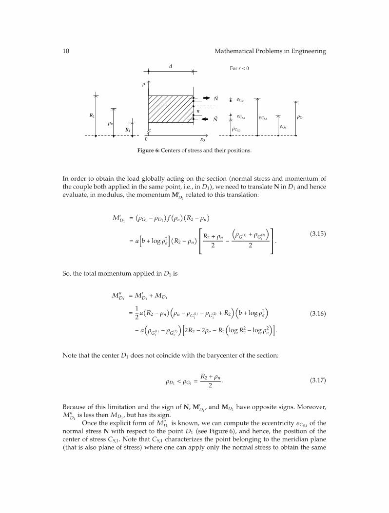
Figure 6: Centers of stress and their positions.
In order to obtain the load globally acting on the section (normal stress and momentum ofthe couple both applied in the same point, i.e., inD1), we need to translateN inD1 and henceevaluate, in modulus, the momentum M′
D1related to this translation:
M′D1
=(ρG1 − ρD1
)f(ρe)(R2 − ρn
)
= a[b + log ρ2e
](R2 − ρn
)⎡⎢⎣R2 + ρn
2−
(ρG
(1)1+ ρ
G(2)1
)
2
⎤⎥⎦.
(3.15)
So, the total momentum applied in D1 is
M′′D1
= M′D1
+MD1
=12a(R2 − ρn
)(ρn − ρ
G(1)1− ρ
G(2)1+ R2
)(b + log ρ2e
)
− a(ρG
(1)1− ρ
G(2)1
)[2R2 − 2ρe − R2
(logR2
2 − log ρ2e)]
.
(3.16)
Note that the centerD1 does not coincide with the barycenter of the section:
ρD1 < ρG1 =R2 + ρn
2. (3.17)
Because of this limitation and the sign of N, M′D1, and MD1 have opposite signs. Moreover,
M′′D1
is less then MD1 , but has its sign.Once the explicit form of M′′
D1is known, we can compute the eccentricity eCS,1 of the
normal stress N with respect to the point D1 (see Figure 6), and hence, the position of thecenter of stress CS,1. Note that CS,1 characterizes the point belonging to the meridian plane(that is also plane of stress) where one can apply only the normal stress to obtain the same

Mathematical Problems in Engineering 11
effect produced by the specific load acting on the bases of the cross-section of the auxiliarybeam. More precisely, in the coordinate-plane (0, ρ,x3),
ρCS,1 = e CS,1+ ρD1 =
M′′D1
N+12
(ρG
(1)1+ ρ
G(2)1
). (3.18)
Finally, since Saint Venant’s theory refers to the barycenter, we have to evaluate themomentum MG1 ofN with respect to G1. So, letting
b′1 = ρCS,1 − ρG1 = −
(ρG
(1)1− ρ
G(2)1
)[2R2 − 2ρe − R2
(logR2
2 − log ρ2e)]
(R2 − ρn
)(b + log ρ2e
) (3.19)
be the arm, we have
MG1 = b′1N = −a(ρG
(1)1− ρ
G(2)1
)[2R2 − 2ρe − R2
(logR2
2 − log ρ2e)]
. (3.20)
Then, in agreement with Saint Venant’s theory, for all z ∈ [0,d] in the section there is theaction of the following linear σ(1)
x3 (ρ) (right combined tensile and bending stress):
σ(1)x3
(ρ)=
N
L1+MG1
IG1
(ρ − R2 + ρn
2
)
= f(ρe) −
12a(ρG
(1)1− ρ
G(2)1
)[2R2 − 2ρe − R2
(logR2
2 − log ρ2e)]
(R2 − ρn
)3(ρ − R2 + ρn
2
)
= a(b + log ρ2e
)+
−12a(ρG
(1)1− ρ
G(2)1
)[2R2 − 2ρe − R2
(logR2
2 − log ρ2e)]
(R2 − ρn
)3(ρ − R2 + ρn
2
).
(3.21)
Actually, L1 is reduced toR2−ρn since the cross-section of the bar has unitary bases; moreover,IG1 = (1/12)(R2−ρn)3, as it is known, is the momentum of inertia in respect to an axis throughG1 and parallel to the bases of the same cross-section.
3.1.2. Lower Section: ρ ∈ [R1, ρn]
Let’s consider the lower sectionwhere ρ ∈ [R1, ρn]. In order to obtain, in Saint Venant’s theory,the explicit form of the stress acting on the bases of the auxiliary beam, we briefly recall thesame strategy amply described in the previous case. So
ρp =√e−(2ρn−2R1−ρn log ρ2n+R1 logR2
1)/(ρn−R1) (3.22)

12 Mathematical Problems in Engineering
is the point where we have to translate the diagram of f(ρ) to obtain the division of the lowersection into two smaller ones with, in modulus, the same area. The normal stress applied tothe barycenter G2 of the section, whose ρG2 = (ρn + R1)/2, is in modulus
N = f(ρp)(ρn − R1
)= a(ρn − R1
)(b + log ρ2p
). (3.23)
Moreover, we can evaluate the couple (C2,−C2)
C2 = a[2(ρn − ρp
) − ρn(log ρ2n − log ρ2p
)], (3.24)
its arm
b2 = ρG
(1)2− ρ
G(2)2
=ρ2n − ρ2p − 2ρ2n
(log ρn − log ρp
)
4[ρn − ρp − ρn
(log ρn − log ρp
)] −ρ2p − R2
1 − 2R21
(log ρp − logR1
)
4[ρp − R1 − R1
(log ρp − logR1
)] ,(3.25)
and clearly the coordinate of its center D2
ρD2 =ρG
(1)2+ ρ
G(2)2
2. (3.26)
Following the same line of reasoning, we can consider
M′′D2
=12a(ρn − R1
)(ρn − ρ
G(2)2− ρ
G(1)2+ R1
)(b + log ρ2p
)
− a(ρG
(1)2− ρ
G(2)2
)[2ρn − 2ρp − ρn
(log ρ2n − log ρ2p
)],
(3.27)
and hence
ρCS,2 = eCS,2 + ρD2 =M′′
D2
N+12
(ρG
(1)2+ ρ
G(2)2
). (3.28)
Finally, since Saint Venant’s theory refers to the barycenter, we have to evaluate themomentum MG2 ofN with respect to G2. So, letting
b′2 = −
(ρG
(1)2− ρ
G(2)2
)[2ρn − 2ρp − ρn
(log ρ2n − log ρ2p
)]
(ρn − R1
)(b + log ρ2p
) (3.29)

Mathematical Problems in Engineering 13
be the arm, we have
MG2 = −a(ρG
(1)2− ρ
G(2)2
)[2ρn − 2ρp − ρn
(log ρ2n − log ρ2p
)]. (3.30)
Thus, in agreement with Saint Venant’s theory, for all z ∈ [0,d] in the section there is theaction of the following linear σ(2)
x3 (ρ) (right combined compressive and bending stress):
σ(2)x3
(ρ)=
N
L2+MG2
IG2
(ρ − R1 + ρn
2
)
= a(b + log ρ2p
)−12a(ρG
(1)2− ρ
G(2)2
)[2ρn − 2ρp − ρn
(log ρ2n − log ρ2p
)]
(ρn − R1
)3(ρ − R1 + ρn
2
).
(3.31)
Actually, L2 is reduced to ρn−R1 since the cross-section of the bar has unitary bases; moreover,IG2 = (1/12)(ρn−R1)
3, as it is known, is the momentum of inertia in respect to an axis throughG2 and parallel to the bases of the same cross-section.
4. Numerical Results
The importance of Saint Venant’s theory applied to the sixth elementary distortions is mainlybased on the information content of (3.21) and (3.31). More precisely, they underline whatkind of load is induced (in Saint Venant’s theory) by the sixth elementary distortion: it is aright combined tensile and bending stress and a right combined compressive and bendingstress. Hence, for every axial section it is possible to evaluate the tensional state with thewell-known Saint Venant’s formulas [15].
However, in order to apply Saint Venant’s theory, our analysis has required someassumptions: we have considered a suitable auxiliary beam and we have assumed that theload on the bases has a linear diagram. So, to evaluate the deviation of our results fromVolterra’s predictions, in this section we compare (3.21) and (3.31) with fx3(ρ) computedby Volterra.
More precisely, let us consider the cylinder made of steel, for which
λ = 1.53 ∗ 10−6 kg/cm2, ν = 7.89 ∗ 105 kg/cm2, (4.1)
and let us subject the side of the cut to this rotation r = −1.62 ∗ 10−5 rad.The smallness of the chosen angle is justified by the required thickness of the cylinder,
by the material it is made of and by the hypothesis that Saint Venant’s theory is valid forsmall displacements.
Moreover, we fixed R2 = 4 cm and then we examined the following two cases:
β =R1
R2= 0.5, β =
R1
R2= 0.9 (4.2)

14 Mathematical Problems in Engineering
3.2 3.4 3.6 3.8 4
0.1
0.2
0.3
0.4
0.5
ρ
β = 0.5
3.06 cm = ρn ≤ ρ ≤ R2 = 4 cmσx3
Figure 7: Load in Volterra’s theory (black) and load in our results (dashed) for β = 0.5. The picture refersto the upper section, that is, 3.06 cm = ρn ≤ ρ ≤ R2 = 4 cm.
2.2 2.4 2.6 2.8 3
−0.8
−0.6
−0.4
−0.2ρ
β = 0.5
2 cm = R1 ≤ ρ ≤ ρn = 3.06 cm
σx3
Figure 8: Load in Volterra’s theory (black) and load in our results (dashed) for β = 0.5. The picture refersto the lower section, that is, 2 cm = R1 ≤ ρ ≤ ρn = 3.06 cm.
from which
R1 = 2 cm, ΔR = 2 cm, R1 = 3.6 cm, ΔR = 0.4 cm. (4.3)
When β = 0.5, in Figures 7 and 8, we have shown the graphics of the different loads. Thesepictures clearly demonstrate that the dashed line (expression of load in our results) is a goodapproximation of Volterra’s prediction. The percent deviation of our result from Volterra’sformula, for different values of ρ, is shown in Figures 9 and 10. This deviation is calculateddividing the difference between the load in Volterra’s theory and the load in our results bythe load in Volterra’s theory. As already underlined in the analytic treatment of the previoussection, apart from a small zone near the neutral axis this deviation is “small”: the “error”made in such approximation can be strongly controlled.
Note that it is not restrictive to consider a small set of fixed ρ as to compute thisdeviation. In fact, apart from a small zone near the neutral axis, which thickness, in both cases,does not exceed the 16% of the thickness of the considered section, this deviation remainsbounded by the same small value. Analyzing Figures 9 and 10, it seems that this value isabout 5.

Mathematical Problems in Engineering 15
Dev
iation
(%)
β = 0.5
3.06 cm = ρn ≤ ρ ≤ R2 = 4 cm
3.2 3.4 3.6 3.8 4
ρ−5
−10
5
10
Figure 9: Graphic representation of the percent deviation of our results from Volterra’s prediction for β =0.5 and 3.06 cm = ρn ≤ ρ ≤ R2 = 4 cm.
2 2.2 2.4 2.6 2.8 3
ρ−5
−10
−15
5
10
15
Dev
iation
(%)
β = 0.5
2 cm = R1 ≤ ρ ≤ ρn = 3.06 cm
Figure 10: Graphic representation of the percent deviation of our results from Volterra’s prediction forβ = 0.5 and 2 cm = R1 ≤ ρ ≤ ρn = 3.06 cm.
We want to underline that since fx3(ρ) tends to zero in this small zone near the neutralaxis, the aforementioned formula is unable to give us information on the percent deviation,that by Figures 7 and 8 is bounded.
Finally, we have compared the obtained numerical results with Volterra’s predictionfor a very thin cylinder. More precisely, when β = 0.9, that is, when that R1 differs little fromR2, in Figures 11 and 12 we have shown the graphics of the different loads. In this case it israther impossible to distinguish between them. Clearly (see Figures 13 and 14), apart from asmall zone near the neutral axis, which thickness, in both cases, does not exceed the 16% ofthe thickness of the considered section, the deviation is also strongly bounded (about by 0.6per cent).
We can conclude by seeing that the values calculated through Saint Venant’s theoryare more strictly related to those calculated by Volterra when the cylinder thickness tends tozero.

16 Mathematical Problems in Engineering
3.8 3.85 3.9 3.95 4
0.02
0.04
0.06
0.08
0.1
ρ
β = 0.9
3.8 cm = ρn ≤ ρ ≤ R2 = 4 cmσx3
Figure 11: Load in Volterra’s theory (black) and load in our results (dashed) for β = 0.9. The picture refersto the upper section, that is, 3.8 cm = ρn ≤ ρ ≤ R2 = 4 cm. Note that the two lines are indistinguishable.
3.65 3.7 3.75 3.8
−0.1
−0.08
−0.06
−0.04
−0.02 ρ
β = 0.9
6 = R1 ≤ ρ ≤ ρn = 3.8 cm3. cm
σx3
Figure 12: Load in Volterra’s theory (black) and load in our results (dashed) for β = 0.9. The picture refersto the lower section, that is, 3.6 cm = R1 ≤ ρ ≤ ρn = 3.8 cm. Note that the two lines are indistinguishable.
5. Conclusions
In this paper we have improved Volterra’s analysis focusing our attention on the loadinduced on the bases by one of the six elementary distortions, the sixth one. Precisely, takingadvantage from the Saint Venant theory, tackled for our case, we have evaluated the natureof this force. In particular, approaching the specific load as linear one and constructing anauxiliary bar which has as longitudinal section the axial section of the cylinder, we haveanalyzed the tensional state with the well known Saint Venant’s principle.
We have obtained the specific load connected to the sixth distortion is equivalent (inSaint Venant’s theory) to a right combined compressive and bending stress and to a rightcombined tensile and bending stress.
As previously underlined, this result is achieved by considering some assumptionsand approximations. So, to evaluate its reliability and precision, we have added numericalsimulations able to visualize, and hence compare, the load given by Volterra and the loadcomputed through the Saint Venant’s theory. The numerical analysis, applied to a thin steelcylinder, demonstrates that we have obtained a good approximations of Volterra’s prediction:in all the analyzed cases, apart from the extinction zone, the deviation between the twoexpression of the same load remains strongly bounded. This gives reason to a possible

Mathematical Problems in Engineering 17
3.8 3.85 3.9 3.95 4−0.5−1
−1.5−2
0.5
1
1.5
2
Dev
iation
(%)
ρ
β = 0.9
= ρn ≤ ρ ≤ R2 = 4 cm3.8 cm
Figure 13: Graphic representation of the percent deviation of our results from Volterra’s prediction forβ = 0.9 and 3.8 cm = ρn ≤ ρ ≤ R2 = 4 cm.
3.6 3.65 3.7 3.75 3.8−0.5−1
−1.5−2
0.5
1
1.5
2
Dev
iation
(%)
ρ
β = 0.9
= R1 ≤ ρ ≤ ρn = 3.8 cm63. cm
Figure 14: Graphic representation of the percent deviation of our results from Volterra’s prediction forβ = 0.9 and 3.6 cm = R1 ≤ ρ ≤ ρn = 3.8 cm.
generalization of the statement. More precisely, we stress that the various results obtainedhere are limited to the analysis of the sixth elementary distortion. As an interesting researchperspective, we aim to address the generalization of our analysis to the case of a generaldistortion as we are planning for forthcoming investigations.
References
[1] M.Weingarten, “Sur les surfaces de discontinuite dans la theorie des corps solids,” Rend. Accad. Lincei,vol. 10, pp. 57–60, 1901.
[2] V. Volterra, “Sulle distorsioni dei corpi elastici simmetrici,” Rend. Accad. Lincei, vol. 14, 1905.[3] V. Volterra, L’equilibre des corps elastique multiplement connexes, Gauthier-Villars, Imprimeur-libraire,
Paris, France, 1907.[4] A. E. H. Love, The Mathematical Theory of Elasticity, Cambridge Univerity Press, Cambridge, UK, 4th
edition, 1952.[5] C. Cattani and J. Rushchitsky, “Volterra’s distortions in nonlinear hyperelastic media,” International
Journal of Applied Mathematics and Mechanics, vol. 3, pp. 14–34, 2005.[6] L. M. Zubov, Nonlinear Theory of Dislocations and Disclinations in Elastic Bodies, vol. 47 of Lecture Notes
in Physics. New Series m: Monographs, Springer, Berlin, Germany, 1997.

18 Mathematical Problems in Engineering
[7] G. Grioli, “Vito Volterra’s work on elastic distortions,” in International Conference in Memory of VitoVolterra, vol. 92 of Atti Convegni Lincei, pp. 271–289, Accad. Naz. Lincei, Rome, Italy, 1992.
[8] G. Caricato, “On the Volterra’s distortions theory,”Meccanica, vol. 35, pp. 411–420, 2000.[9] E. Laserra and M. Pecoraro, “Volterra’s theory of elastic dislocations for a transversally isotropic
homogeneous hollow cylinder,” Nonlinear Oscillations, vol. 6, no. 1, pp. 56–73, 2003.[10] I. Bochicchio, E. Laserra, and M. Pecoraro, “Sulla sesta distorsione elementare di Volterra per un
cilindro cavo omogeneo e isotropo di altezza finita con carico alla Saint Venant,” Atti dell’ AccademiaPeloritana dei Pericolanti, Classe di Scienze Fisiche, Matematiche e Naturali, vol. 86, no. 1, Article IDC1A0801003, 2008.
[11] I. Bochicchio, E. Laserra, and M. Pecoraro, “Sul Carico alla De Saint Venant della Sesta DistorsioneElementare di Volterra,” in Math. Phys. Mod. Eng. Sciences, Societa nazionale di scienze letterarie e arti inNapoli, Studi in onore di Pasquale Renno, pp. 9–15, Liguori Editore, 2008.
[12] A. Signorini, Lezioni di Fisica Matematica, Libreria Eredi Virgilio Veschi, Roma, Italy, 1953.[13] A. I. Lurie, Theory of Elasticity, Springer, Berlin, Germany, 2005.[14] P. Villaggio, Mathematical Models for Elastic Structures, Cambridge University Press, Cambridge, UK,
1997.[15] D. Iesan, Saint-Venant’s Problem, Springer, Berlin, Germany, 2008.

Submit your manuscripts athttp://www.hindawi.com
Hindawi Publishing Corporationhttp://www.hindawi.com Volume 2014
MathematicsJournal of
Hindawi Publishing Corporationhttp://www.hindawi.com Volume 2014
Mathematical Problems in Engineering
Hindawi Publishing Corporationhttp://www.hindawi.com
Differential EquationsInternational Journal of
Volume 2014
Applied MathematicsJournal of
Hindawi Publishing Corporationhttp://www.hindawi.com Volume 2014
Probability and StatisticsHindawi Publishing Corporationhttp://www.hindawi.com Volume 2014
Journal of
Hindawi Publishing Corporationhttp://www.hindawi.com Volume 2014
Mathematical PhysicsAdvances in
Complex AnalysisJournal of
Hindawi Publishing Corporationhttp://www.hindawi.com Volume 2014
OptimizationJournal of
Hindawi Publishing Corporationhttp://www.hindawi.com Volume 2014
CombinatoricsHindawi Publishing Corporationhttp://www.hindawi.com Volume 2014
International Journal of
Hindawi Publishing Corporationhttp://www.hindawi.com Volume 2014
Operations ResearchAdvances in
Journal of
Hindawi Publishing Corporationhttp://www.hindawi.com Volume 2014
Function Spaces
Abstract and Applied AnalysisHindawi Publishing Corporationhttp://www.hindawi.com Volume 2014
International Journal of Mathematics and Mathematical Sciences
Hindawi Publishing Corporationhttp://www.hindawi.com Volume 2014
The Scientific World JournalHindawi Publishing Corporation http://www.hindawi.com Volume 2014
Hindawi Publishing Corporationhttp://www.hindawi.com Volume 2014
Algebra
Discrete Dynamics in Nature and Society
Hindawi Publishing Corporationhttp://www.hindawi.com Volume 2014
Hindawi Publishing Corporationhttp://www.hindawi.com Volume 2014
Decision SciencesAdvances in
Discrete MathematicsJournal of
Hindawi Publishing Corporationhttp://www.hindawi.com
Volume 2014 Hindawi Publishing Corporationhttp://www.hindawi.com Volume 2014
Stochastic AnalysisInternational Journal of


![ON SAINT-VENANT'S PRINCIPLE*...1954] ON SAINT-VENANT'S PRINCIPLE 397 in place of Sk , P'nk), r(0k). Let S and P0 be contained in an open simply connected sub-region S* of B (Figure](https://img.dokumen.tips/doc/110x75/608f36a0f8d00c4261762b9f/on-saint-venants-principle-1954-on-saint-venants-principle-397-in-place.jpg)


