Embed Size (px)
Citation preview
© 2021 The Author(s). Published by the Royal Society of Chemistry Mater. Adv., 2021, 2, 5967–5976 | 5967
Cite this: Mater. Adv., 2021,
2, 5967
An anticounterfeiting technology combining anInP nanoparticle ink and a versatile optical devicefor authentication†
Didem Tas-cıoglu, ab Seçil Sevim Unluturk‡c and Serdar Ozçelik *c
Counterfeiting is a growing issue and causes economic losses. Fluorescent inks containing In(Zn)P/ZnS/
DDT colloidal nanoparticles are formulated and combined with a convenient optical device for
authentication. The particle size and fluorescent colors of the colloidal nanoparticles were tuned by
adjusting the reaction temperature. The particle stability and brightness were improved by the addition of
dodecanethiol, coating the particle surface with an organic shell. Security patterns were printed on
various substrates by applying the screen-printing technique. The patterns were invisible under daylight
but observable under UV-light illumination, displaying five different emission colors. By adjusting the
concentration of the nanoparticles in the ink, the security patterns were made almost not observable
under UV-light illumination but clearly identified by a commercial fiber optics-based spectrometer and a
handheld optical device, called a Quantag sensor that was developed in-house. Furthermore, the spectral
signatures of barely noticeable patterns are unambiguously validated by the Quantag sensor. Accordingly,
low cost and easily applicable anticounterfeiting technology powered by custom-formulated fluorescent
inks and a handheld optical instrument are developed to authenticate valuable documents and products.
1. Introduction
Counterfeiting and adulteration of valuable documents cause eco-nomical losses and initiate societal concerns. Anticounterfeitingefforts require advanced materials and technologies to preventcounterfeiting. Fluorescent inks are commonly used as second-level security features; being invisible in the daylight and detectableunder UV light. In the last decade, to prevent counterfeiting, securitylabels have been created using different printing techniques withvarious fluorescent inks formulated by using rare earth luminescentmaterials,1–6 perovskite nanocrystals,7,8 carbon dots,9–11 organicdyes,12,13 and quantum dots.14–16 Among various printing methods,screen printing is preferable because it is easily applicable to varioussubstrates.17 Screen printing is a unique technique in terms of
quality; it is a process that uses ink or pastes pushed by a templateattached or embedded in a web stretched onto a printing frame.Since an intermediate transfer tool is not required, the consistencyof the ink is not limited. Long-lasting and durable prints can beproduced, providing unrivaled homogeneity and color brilliance.Screen printing can be applied to a variety of substrates from papersto metals to plastics, and even glass and ceramics. These capabilitiesenable the production of a wide variety of products including smartidentity cards, credit cards, technical and industrial parts, automo-bile components, flat glass and glass containers, etc.18
In the past several years, publications applying screen-printingtechniques using lanthanide-based luminescent materials havebeen widely reported for anticounterfeiting.6,19–22 Organic dyes asfluorescent materials are used in this field.12,23 Colloidal quantumdots (cQDs) are considered alternatives to these materials because oftheir unique optical properties.24,25 Unlike the lightfastness andcost-effectiveness of lanthanide-based materials and broad emissionpeaks of organic dyes,26 cQDs possess narrow, stable, and tunablephotoluminescence emission features.27 In addition, cQDs may beexcited by a single wavelength light source because of their broadabsorption spectra. With all these distinctive features, cQDs may beregarded as an excellent anticounterfeiting material for contempor-ary security ink and printing technology.
To prevent counterfeiting, luminescent/fluorescent materi-als are turned into colorless fluorescent inks that exhibitconfidential information when exposed to UV light.28–30
a Department of Material Science and Engineering, Izmir Institute of Technology,
Urla, 35430, Izmir, Turkeyb Quantag Nanotechnologies, R&D Lab, Budotek Teknopark, Dudullu OSB
Umraniye, 34776, Istanbul, Turkeyc Department of Chemistry, Izmir Institute of Technology, Urla, 35430, Izmir,
Turkey. E-mail: [email protected]; Tel: +90 232 750 75 57
† Electronic supplementary information (ESI) available: DDT effect on photo-physical properties and relevant characterization details and supporting photo-graphs; the photo of the screen printing device; the PL spectra of varnish andscreen printed paper samples (PDF). See DOI: 10.1039/d1ma00383f‡ The current address of the author, Seçil SEVIM UNLUTURK, is Micro-Electro-Mechanical Systems Research and Application Center (METU-MEMS), MiddleEast Technical University, Çankaya, 06530, Ankara, Turkey.
Received 28th April 2021,Accepted 3rd August 2021
DOI: 10.1039/d1ma00383f
rsc.li/materials-advances
MaterialsAdvances
PAPER
Ope
n A
cces
s A
rtic
le. P
ublis
hed
on 0
4 A
ugus
t 202
1. D
ownl
oade
d on
1/2
7/20
22 3
:20:
55 P
M.
Thi
s ar
ticle
is li
cens
ed u
nder
a C
reat
ive
Com
mon
s A
ttrib
utio
n-N
onC
omm
erci
al 3
.0 U
npor
ted
Lic
ence
.
View Article OnlineView Journal | View Issue

5968 | Mater. Adv., 2021, 2, 5967–5976 © 2021 The Author(s). Published by the Royal Society of Chemistry
However, as these materials often exhibit monochromaticemissions that are easy to imitate, these security inks offer alow level of protection against counterfeiting. In recent years,luminescent inks made of rare-earth materials have attractedgreat attention due to their fast response time, high brightness,and efficiency.31–34 However, rare-earth materials-based secur-ity inks severely limit scaled-up production due to high cost.Furthermore, it is desired to verify the authenticity of a docu-ment illuminated under UV light by visual inspection withoutusing a device.29,32 However, this simplicity would make secur-ity patterns predictable and can be easily reproduced. Toprevent counterfeiting, utilizing an affordable, widely-used,handy instrument such as a mobile phone or an optical deviceworking with a specially formulated ink may enhance antic-ounterfeiting procedures.
In this study, we formulated a colloidal nanoparticle (col-loidal quantum dot)-based security ink to authenticate valuabledocuments. Here, we chose indium-based alloyed nano-particles because the cost of indium-based precursors is muchlower than that of the rare-earth element-based materials. Ontop of that, they can be easily produced at hundreds of grams inone pot,35,36 thereby further lowering the ink cost. Herein, wesynthesized In(Zn)P/ZnS/DDT nanoparticles to formulate secur-ity inks emitting brightly in various colors. Fluorescence prop-erties of the nanoparticles were adjusted by the reactiontemperature, tuning the particle size generating various fluor-escent colors. The In(Zn)P/ZnS/DDT colloidal nanoparticleswere mixed with a commercial printing varnish to formulatesecurity inks. The inks were used to print security patterns onvarious substrates including paper, polymer, and glass byapplying the screen-printing technique. The security patternsprinted were evaluated by using a commercial fiber optics-based spectrometer, and a low-cost, convenient handheld opti-cal device, called a Quantag sensor developed in-house byQuantag Nanotechnologies. The security patterns that werebarely detectable under UV light by the naked eye were clearlydetectable by the Quantag sensor. The spectral features, wave-lengths, and brightness, were validated by a fiber optics-basedspectrometer, verifying the readings of the Quantag sensor. It isdemonstrated that the security patterns can be printed by usingthe specially formulated ink and detected at a low cost, using asimple and handy optical device to authenticate the originalityof documents or products.
2. Experimental2.1. Materials and methods
Indium(III) chloride (InCl3, 98%), oleylamine (OA, 70%), trioc-tylphosphine (TOP, 97%), zinc stearate (technical grade), 1-octadecene (ODE, 90%), 1-dodecanethiol (DDT, Z98%), sulfur(Merck, 99%) and toluene (ACS reagent, Z99.7%) were pur-chased from Sigma-Aldrich. Zinc(II) chloride (ZnCl2, 97%) andtris(diethylamino)phosphine ((DEA)3P, 97%) were purchasedfrom Alfa Aesar. Printcolor series 592 varnish was used toformulate inks.
Photoluminescence (PL) and quantum yield (QY)% measure-ments were performed using a Horiba-Fluorolog with an inte-grated sphere or USB2000 fiber optics-based spectrometer(Ocean Optics Inc., Dunedin, FL, USA). Absorbance was mea-sured using a Shimadzu UV-3600 UV-vis-NIR spectrophot-ometer. Particle size measurements were obtained using aDLS (Malvern ZS-Zetasizer). SEM-EDS analysis employed anFEI QUANTA 250 FEG SEM equipped with an Oxford Instru-ments energy dispersive X-ray analyzer. XRD patterns wereobtained using a Bruker D2 phaser-X-ray diffractometer. Four-ier transform infrared spectroscopy (FTIR; Thermo ScientificiS10 FT-IR) was used to confirm DDT coating. The thickness ofthe screen-printed patterns was measured using a KlaTencorMicroXM-100 optical profilometer. An Andor Revolution con-focal microscope was used to determine ink homogeneity in theprinted patterns. The Quantag sensor is a fiber optics-baseddevice developed in-house (patent protected). It is a handheldand low-cost optical instrument utilizing fiber optical probes todetect and measure fluorescence intensity (brightness) andcolors (wavelength) of inks embedded into patterns printedon substrates.
2.2. Synthesis of In(Zn)P core and In(Zn)P/ZnS/DDT core/shellnanoparticles
In(Zn)P/ZnS/DDT colloidal nanoparticles were synthesized byapplying a modified hot injection method.37 Briefly, 0.9 mmolof InCl3 and 4.4 mmol of ZnCl2 were mixed in 10.0 mL ofoleylamine at 120 1C and stirred for 20 min. After the indiumand zinc precursors were completely dissolved under a nitrogenatmosphere, the reaction temperature was increased to aspecific predetermined value (varied from 150 to 200 1C).3.3 mmol tris(diethylamino)phosphine ((DEA)3P) was rapidlyinjected into the precursor solution to synthesize the core ofIn(Zn)P nanoparticles. To coat the nanoparticle surface with aZnS shell, TOP-S and Zn(stearate)2 were prepared individuallyand added dropwise into the In(Zn)P core nanoparticle disper-sion. Firstly, 2 mL of 2.2 M TOP-S and 8 mL of 0.4 MZn(stearate)2 solutions were simultaneously injected into thereaction medium and the reaction temperature was increasedto 300 1C. After one hour, 1.4 mL of 2.2 M TOP-S and 8 mL of0.4 M Zn(stearate)2 solutions were added as the second injec-tion. The formation of additional layers was established at 30min and 15 min, respectively, following the second injection.After the formation of a multilayered ZnS shell coating, thereaction was cooled down to 120 1C. At this temperature, DDTwas injected into the dispersion to grow an organic passivationlayer over the nanoparticle surface. The dispersion was stirredfor 20 minutes more and then the reaction was terminated bycooling the dispersion to room temperature (Fig. S1, ESI†).
To purify the crude In(Zn)P/ZnS/DDT nanoparticles, thedispersion was precipitated by the addition of ethanol andthen centrifugated at 6000 rpm for 15 minutes. This purifica-tion step was repeated one more time to remove remainingunreacted precursors and excessive amounts of organics. Pur-ified In(Zn)P/ZnS/DDT nanoparticles were dried under avacuum and stored as powders.
Paper Materials Advances
Ope
n A
cces
s A
rtic
le. P
ublis
hed
on 0
4 A
ugus
t 202
1. D
ownl
oade
d on
1/2
7/20
22 3
:20:
55 P
M.
Thi
s ar
ticle
is li
cens
ed u
nder
a C
reat
ive
Com
mon
s A
ttrib
utio
n-N
onC
omm
erci
al 3
.0 U
npor
ted
Lic
ence
.View Article Online

© 2021 The Author(s). Published by the Royal Society of Chemistry Mater. Adv., 2021, 2, 5967–5976 | 5969
2.3. Printing process
In(Zn)P/ZnS/DDT nanoparticles were dispersed in a commer-cial varnish/toluene mixture with a ratio of 0.1–0.2% v/v (1000–2000 ppm). This ink was used to print security patterns onvarious substrates by using a screen-printer.
3. Results and discussions3.1. In(Zn)P/ZnS/DDT nanoparticles
Recently, III–V semiconductors have gained attention because theyhave typically a higher covalent character than ionic materials (II–VIand IV–VI materials), resulting in improved optical stability andlower toxicity.38 The Bohr radii of III–V systems are larger comparedto II–VI materials, which create stronger quantum confinement.39
InP among all III–V semiconductors is of great interest due to itsstability and low toxicity compared to heavy metals cadmium andmercury.40 The bulk bandgap of InP is 1.35 eV (918 nm) having alarge Bohr radius that generates a wider optical range from visible tonear-infrared (NIR).41 We preferred to synthesize In(Zn)P/ZnS/DDTcolloidal nanoparticles for anticounterfeit applications because oflow toxicity and high brightness.
As shown in Fig. 1, increasing the reaction temperatureresulted in redshifts in the absorption spectra. The particlesize of the nanoparticle core was measured by the DLS(dynamic light scattering) technique (Fig. 1b), confirming thatthe increase in nanoparticle size from 5.6 to 13.5 nm wascorrelated to the observed red-shifted absorption spectra.Despite a well-defined absorption band of In(Zn)P core nano-particles, weak photoluminescence was observed. Nonradiativerelaxations due to the surface defects cause weaker emissionsfor InP nanoparticles unless a proper inorganic shell is coatedon the surface of the core nanoparticle.42 XRD patterns of thecore nanoparticles revealed the formation of low-quality nano-crystalline structures (Fig. S2a, ESI†). XRD measurements indi-cated the formation of the ZnO layer (JCPDS: 36-1451) on the
particle surface due to the oxidation of Zn ions (Fig. S2a, ESI†).As demonstrated in the literature,43,44 the InP core generallygenerates low fluorescence emission (quantum yield less than1%) and is prone to photodegradation and surface oxidation.Coating the core with a larger bandgap semiconductor materialsuch as ZnS is a common method to improve fluorescenceefficiency by passivating the core surface and diminishingdangling bonds.45 Herein, ZnS was chosen as the shell layermaterial because it has high chemical stability and a widebandgap (3.6 eV), and low-cost precursors are commerciallyavailable.46,47 When the core nanoparticle was coated with ZnSshell, In(Zn)P/ZnS nanoparticles emitted in the range of 535-638 nm with higher quantum yields (Fig. 2b and Table 1). XRDpatterns show better diffractograms suggesting improved crys-tal structures and well-defined (111), (220), and (311) facetsestablished after ZnS/DDT shell growth on the particle surface(Fig. S2b and c, ESI†).
The fluorescent colors of the nanoparticles were tuned byadjusting the reaction temperature, which increased from 150to 200 1C. The bright visible emission under UV illumination isan indication of the highly efficient fluorescence emissionshown in the inset of Fig. 2a. For all reaction temperatures,the FWHM of nanoparticles were comparable (Fig. 2b). (DEA)3Pwas used as the phosphorus source because its higher sterichindrance reduces chemical reactivity and consequentlyleads to stable and high-quality nanocrystals.37,45 Other phos-phorus sources tris(trimethylsilyl)-phosphine ((TMS)3P), andtris(dimethylamino) phosphine ((DMA)3P) were not chosenbecause (TMS)3P is highly flammable, toxic, and expensive37
and (DMA)3P has high reactivity because it has lower sterichindrance.48
The point of incorporating Zn ions into the InP crystal wasto reduce structural strain due to lattice mismatch between theInP core and ZnS shell layer.49,50 Incorporated Zn ions alleviatethe lattice tension51 between the core and the shell layers.The successful growth of the ZnS ensures higher quantum
Fig. 1 (a) Absorption spectra and (b) particle size and distribution of In(Zn)P core nanoparticles, tuned by the reaction temperature but keeping thereaction time fixed.
Materials Advances Paper
Ope
n A
cces
s A
rtic
le. P
ublis
hed
on 0
4 A
ugus
t 202
1. D
ownl
oade
d on
1/2
7/20
22 3
:20:
55 P
M.
Thi
s ar
ticle
is li
cens
ed u
nder
a C
reat
ive
Com
mon
s A
ttrib
utio
n-N
onC
omm
erci
al 3
.0 U
npor
ted
Lic
ence
.View Article Online

5970 | Mater. Adv., 2021, 2, 5967–5976 © 2021 The Author(s). Published by the Royal Society of Chemistry
yields for the alloyed nanoparticles. Atom% values of theelements for In(Zn)P core nanoparticles were determined usingSEM-EDS measurements and are provided in Table 2. Fig. 3demonstrates that the fractions of Zn and In in the alloy werenot varying with the reaction temperatures. The alloy composi-tion of the core remained unchanged with the reaction tem-perature. This finding suggested that the red-shifted spectra(absorption and photoluminescence) were tuned by the particlesize rather than the alloy composition. Since the ionic radius ofIn3+ (80 pm) is not significantly larger than the ionic radius ofZn2+ (74 pm),52 it was demonstrated that by keeping thereaction time fixed the reaction temperature is an effectiveparameter to tune the particle size and to regulate the spectral
properties of In(Zn)P nanoparticles. In general, the reactiontime is preferred to tune particle size keeping the reactiontemperature constant. Higher reaction temperatures did not
Fig. 2 (a) Fluorescence spectra of In(Zn)P/ZnS/DDT core/shell nanoparticles tuned by the reaction temperature. Excitation wavelengths for the samplesfrom 150 1C to 200 1C are 365 nm, 375 nm, 375 nm, 405 nm, and 450 nm, respectively. (b) Evolution of the fluorescence quantum yield (QY) percent andthe FWHM of the spectra with respect to the emission wavelengths (increasing core reaction temperature resulted in a redshift in fluorescence maxima –from left to right). Highly concentrated samples were deliberately prepared to exhibit fluorescence colors under daylight and UV-light illumination.
Table 1 Photophysical properties of In(Zn)P/ZnS/DDT nanoparticles pre-pared at various reaction temperatures
Reaction temperaturePLmax
(nm)Absmax
(nm)Stokes shift(nm)
FWHM(nm)
QY(%)
150 1C 535 470 65 68 72160 1C 550 490 60 65 80170 1C 573 505 68 70 85180 1C 602 518 84 65 75200 1C 638 565 63 68 62
Table 2 Alloy compositions and particle diameters of core In(Zn)P nanoparticles synthesized at different reaction temperatures, analyzed by SEM-EDSand DLS measurements
Reaction temperature Core type
Atom %
Size (nm)P Zn In In/(In + Zn) Zn/(In + Zn) Zn/In
150 1C In0.18Zn0.82P 15.8 69.3 14.9 0.18 0.82 4.7 5.6160 1C In0.19Zn0.81P 16.9 67.6 15.6 0.19 0.81 4.3 8.7170 1C In0.21Zn0.79P 14.4 67.6 18.1 0.21 0.79 3.7 10.1180 1C In0.23Zn0.77P 29.3 54.8 16.0 0.23 0.77 3.4 11.6200 1C In0.18Zn0.82P 21.9 64.1 14.0 0.18 0.82 4.6 13.5
Fig. 3 Variation of Zn and In fractions of the nanoparticles as a function ofthe reaction temperature, determined by SEM-EDS measurements. Thecompositions of the core nanoparticles remained constant.
Paper Materials Advances
Ope
n A
cces
s A
rtic
le. P
ublis
hed
on 0
4 A
ugus
t 202
1. D
ownl
oade
d on
1/2
7/20
22 3
:20:
55 P
M.
Thi
s ar
ticle
is li
cens
ed u
nder
a C
reat
ive
Com
mon
s A
ttrib
utio
n-N
onC
omm
erci
al 3
.0 U
npor
ted
Lic
ence
.View Article Online

© 2021 The Author(s). Published by the Royal Society of Chemistry Mater. Adv., 2021, 2, 5967–5976 | 5971
alter the zinc blende crystal structure of In(Zn)P/ZnS/DDT core/shell nanoparticles (Fig. 4), as verified by the identical XRDpatterns.53 The (111), (220), and (311) planes shown in Fig. 4were between the reference lines of InP (JCDS 32-452) and ZnS(JCPDS 77-2100). The shifts in the XRD peaks were observeddepending on the different core reaction temperatures. Itexplains that the core reaction temperature affects the shelltype of In(Zn)P/ZnS nanoparticles as gradient or discrete shelllayers. As a result, the length of the unit cell – lattice constantchanges, and the strains of the nanoparticles are affected.54
Consequently, the shifts in the XRD pattern were observed.Real-time, in situ PL spectra measured using an Ocean
Optics fiber optics spectrometer were used to monitor theimpact of the DDT coating on the fluorescence spectra. Thebifurcated fiber-optic probe inserted in the batch reactor shown
in Fig. 5a was used to excite nanoparticles at 405 nm andto collect fluorescence emissions with an integration time of100 milliseconds. Fig. 5b shows the time-evolved fluorescencespectra of the nanoparticles with and without ZnS and DDTlayers combined. The fluorescence intensity of the DDT-coatednanoparticles was further monitored over 35 days to demon-strate the stability of the nanoparticles (Fig. 5c). The addition ofinorganic and organic layers significantly improved the fluores-cence emission intensity. The quantum yields of the nano-particles were significantly increased by the addition of DDT inthe last step of the reaction because it provides an organic shelllayer to passivate surfaces and increase particle stability.55,56 Itwas also observed that the peak position and shape of thefluorescence spectrum during the shell layer formation did notchange. The unchanged spectral features confirm that thefluorescence emission is due to the electron–hole pairs (exci-tons) confined in the nanoparticle core.57 The DDT coatingincreased fluorescence intensity by enabling surface passiva-tion of the core/shell alloyed nanoparticles.58 Since DDT has arelatively shorter alkyl chain, the steric hindrance is less thanthe other mostly used organic ligands, and thereby highersurface coverage of DDT may be established to prevent photo-degradation of the nanoparticles (Fig. S3, ESI†). A slight blueshifting in the fluorescence spectrum after DDT addition wasobserved and attributed to ion exchange between smaller S2�
ions from DDT and larger P3� ions in the nanoparticles.59
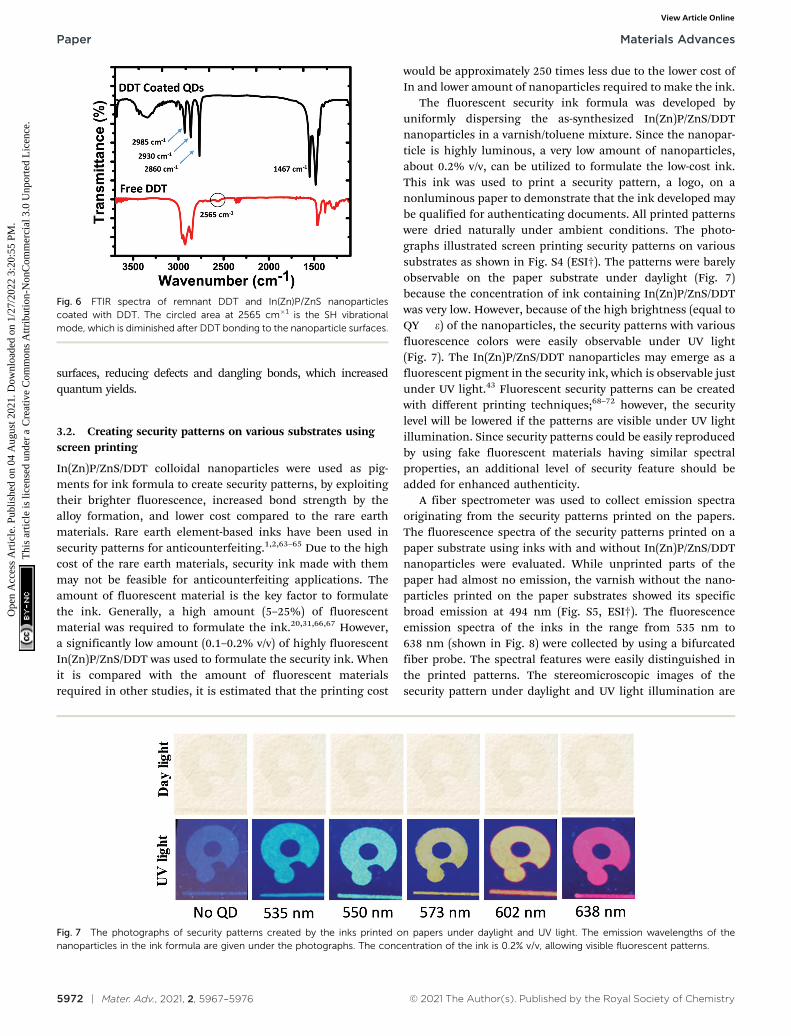
FTIR spectra of DDT remnant in solution and adsorbed ontoInP/ZnS nanoparticle surfaces are shown in Fig. 6. 2985, 2930,and 2860 cm�1 bands are assigned to C–H stretching, and theband at 1467 cm�1 is assigned to CH2 bending.60 The absenceof the band at 2565 cm�1 indicating the stretching vibrationmode of S–H (shown with a circle) proved that the DDT ligand wassuccessfully attached to the nanoparticle surface.61,62 It is assumedthat DDT molecules are bonded to In or Zn atoms on the nano-particle surface through its sulfur atom. The sharpness of the C–Hstretching and CH2 bending modes suggests synchronized in-phasevibrations, inferring that DDT molecules are very well aligned on the
Fig. 4 XRD patterns of In(Zn)P/ZnS core/shell nanoparticles grown atdifferent reaction temperatures. Black and blue colored vertical lines atthe bottom of the figure are added as the reference lines for InP and ZnS,respectively. The XRD patterns of the core nanoparticles are provided inthe supplement.
Fig. 5 (a) Photograph of the reaction set-up allowing in situ and real-time fluorescence measurements and (b) in situ fluorescence spectra recorded byan Ocean Optics fiber optics spectrometer using a bifurcated fiber-optic probe. The excitation wavelength of the samples is 415 nm. (c) The time-evolved fluorescence spectra and improved photostability of the nanoparticles with and without DDT coating.
Materials Advances Paper
Ope
n A
cces
s A
rtic
le. P
ublis
hed
on 0
4 A
ugus
t 202
1. D
ownl
oade
d on
1/2
7/20
22 3
:20:
55 P
M.
Thi
s ar
ticle
is li
cens
ed u
nder
a C
reat
ive
Com
mon
s A
ttrib
utio
n-N
onC
omm
erci
al 3
.0 U
npor
ted
Lic
ence
.View Article Online
5972 | Mater. Adv., 2021, 2, 5967–5976 © 2021 The Author(s). Published by the Royal Society of Chemistry
surfaces, reducing defects and dangling bonds, which increasedquantum yields.
3.2. Creating security patterns on various substrates usingscreen printing
In(Zn)P/ZnS/DDT colloidal nanoparticles were used as pig-ments for ink formula to create security patterns, by exploitingtheir brighter fluorescence, increased bond strength by thealloy formation, and lower cost compared to the rare earthmaterials. Rare earth element-based inks have been used insecurity patterns for anticounterfeiting.1,2,63–65 Due to the highcost of the rare earth materials, security ink made with themmay not be feasible for anticounterfeiting applications. Theamount of fluorescent material is the key factor to formulatethe ink. Generally, a high amount (5–25%) of fluorescentmaterial was required to formulate the ink.20,31,66,67 However,a significantly low amount (0.1–0.2% v/v) of highly fluorescentIn(Zn)P/ZnS/DDT was used to formulate the security ink. Whenit is compared with the amount of fluorescent materialsrequired in other studies, it is estimated that the printing cost
would be approximately 250 times less due to the lower cost ofIn and lower amount of nanoparticles required to make the ink.
The fluorescent security ink formula was developed byuniformly dispersing the as-synthesized In(Zn)P/ZnS/DDTnanoparticles in a varnish/toluene mixture. Since the nanopar-ticle is highly luminous, a very low amount of nanoparticles,about 0.2% v/v, can be utilized to formulate the low-cost ink.This ink was used to print a security pattern, a logo, on anonluminous paper to demonstrate that the ink developed maybe qualified for authenticating documents. All printed patternswere dried naturally under ambient conditions. The photo-graphs illustrated screen printing security patterns on varioussubstrates as shown in Fig. S4 (ESI†). The patterns were barelyobservable on the paper substrate under daylight (Fig. 7)because the concentration of ink containing In(Zn)P/ZnS/DDTwas very low. However, because of the high brightness (equal toQY � e) of the nanoparticles, the security patterns with variousfluorescence colors were easily observable under UV light(Fig. 7). The In(Zn)P/ZnS/DDT nanoparticles may emerge as afluorescent pigment in the security ink, which is observable justunder UV light.43 Fluorescent security patterns can be createdwith different printing techniques;68–72 however, the securitylevel will be lowered if the patterns are visible under UV lightillumination. Since security patterns could be easily reproducedby using fake fluorescent materials having similar spectralproperties, an additional level of security feature should beadded for enhanced authenticity.
A fiber spectrometer was used to collect emission spectraoriginating from the security patterns printed on the papers.The fluorescence spectra of the security patterns printed on apaper substrate using inks with and without In(Zn)P/ZnS/DDTnanoparticles were evaluated. While unprinted parts of thepaper had almost no emission, the varnish without the nano-particles printed on the paper substrates showed its specificbroad emission at 494 nm (Fig. S5, ESI†). The fluorescenceemission spectra of the inks in the range from 535 nm to638 nm (shown in Fig. 8) were collected by using a bifurcatedfiber probe. The spectral features were easily distinguished inthe printed patterns. The stereomicroscopic images of thesecurity pattern under daylight and UV light illumination are
Fig. 6 FTIR spectra of remnant DDT and In(Zn)P/ZnS nanoparticlescoated with DDT. The circled area at 2565 cm�1 is the SH vibrationalmode, which is diminished after DDT bonding to the nanoparticle surfaces.
Fig. 7 The photographs of security patterns created by the inks printed on papers under daylight and UV light. The emission wavelengths of thenanoparticles in the ink formula are given under the photographs. The concentration of the ink is 0.2% v/v, allowing visible fluorescent patterns.
Paper Materials Advances
Ope
n A
cces
s A
rtic
le. P
ublis
hed
on 0
4 A
ugus
t 202
1. D
ownl
oade
d on
1/2
7/20
22 3
:20:
55 P
M.
Thi
s ar
ticle
is li
cens
ed u
nder
a C
reat
ive
Com
mon
s A
ttrib
utio
n-N
onC
omm
erci
al 3
.0 U
npor
ted
Lic
ence
.View Article Online

© 2021 The Author(s). Published by the Royal Society of Chemistry Mater. Adv., 2021, 2, 5967–5976 | 5973
also shown in Fig. S6 (ESI†). The patterns were invisible underdaylight in all the photographs. However, the patterns printedon the papers were easily observable under UV illumination.The homogeneity of the patterns indicates that nanoparticlesare homogeneously distributed within the printed area.
To commercialize security inks, it is desired that securitylabels/codes should be produced by a low-cost ink and verifiedby a simple technique. Generally, the color information offluorescent inks is encoded by tagging an anticounterfeitingpattern embedded onto substrates. To enhance the securitylevel for anticounterfeiting, either advanced materials and/ortechniques should be developed for verification of authenticity.Dual-excitation wavelength materials were used, so thatthe security pattern could be excited at two differentwavelengths.9,20,73,74 QR codes printed on products are alsoused as identification through reading by a device.3 However,since these codes can be completely duplicated, it lowers thesecurity level. When an original QR code and a copied code areplaced side by side and scanned by a smartphone, it will be veryhard to identify which one is fake and which one is authentic.However, imitation can be made difficult to some extent whentwo different methods are applied. Herein, we developed atechnology combining an optical device that reads novel secur-ity patterns/tags created with a specialty ink formula. Thus,unlike other studies, we can verify the security patterns/codeswith a device that has optical sensitivity beyond visual inspec-tion. To this end, a cost-effective fluorescent ink containingindium-based nanoparticles is formulated, enabling very lowamounts of nanoparticles to be required in the ink. In addition,an optical device having an integrated light source and sensoris developed in-house. By virtue of the novel security tagscontaining low amounts of nanoparticles, the ink fluorescencemay not be noticeable or hardly observable under UV light byvisual inspection. The concentration of the nanoparticles in the
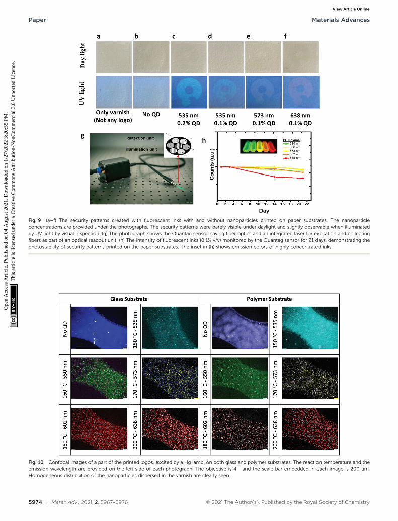
ink was reduced to 0.1% v/v. In Fig. 9a–f, the created securitypatterns/tags are presented under daylight and UV light. Anadditional varnish layer has been applied onto the securityprinting, and as a result, the security labels were not noticedeven with the naked eye. In this way, security labels that aredifficult to distinguish even under daylight have been created.In addition, fluorescent security patterns with distinct colorsunder UV illumination were not distinguishable due to the lowconcentration of nanoparticles in the ink. Herein, we used afiber optics-based optical device (Quantag Sensor) that wasemployed to detect fluorescence emissions of the ink(Fig. 9g). The Quantag sensor includes one excitation fiberbringing a laser to the substrate to excite the ink, and collectionfibers integrated with bandpass filters transmitting selectedemissions to the sensor.75 The fluorescence intensities of theinks with different colors were detectable by the Quantagsensor, shown in Fig. 9h, but invisible by visual inspection(Fig. 9a–f). The Quantag sensor is highly sensitive, convenient,and specific to a predetermined wavelength compared to afiber-optic spectrometer. These features add an extra securitylevel for anticounterfeiting efforts. The fiber-optic spectrometercollects all the emissions including ink, varnish, and sub-strates, and cannot sort out the origin of the signals comingfrom different sources like the nanoparticles or varnish. How-ever, since the Quantag sensor exploits emission filters, thepredetermined emissions may be employed as a higher-levelsecurity code. The reduced ownership and operational costsand wavelength selectivity are also the advantages of theQuantag sensor compared to a commercial fiber-optic spectro-meter, on top of being handy.
The photostability of the ink (0.1% v/v) embedded on the papersubstrate was monitored for 21 days by the Quantag sensor. Thefluorescence of the security patterns monitored proved that theintensities of the patterns were unchanged, as shown in Fig. 9h.The reduction in the intensity of the red-emitting ink (638 nm) maybe explained by some sort of environmental effects on the nano-particles emitting in this wavelength.
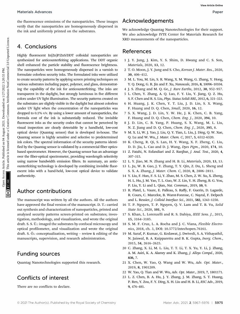
To understand the effect of substrate on the security pattern,the inks were applied to various substrates. The thickness ofthe patterns screen-printed on polymer and glass substrateswas measured using an optical profilometer (Fig. S8, ESI†). Thethickness of the patterns was about 4.5 mm. These measure-ments confirmed that the security patterns form a thin filmcontaining nanoparticles distributed homogeneously on theprinted part of the substrates. The particle sizes have no effectson the film thickness. The confocal images are given in Fig. 10showing some part of the logo patterns printed on the glass andpolymer substrates. The logos were observable on the glass andpolymer surfaces. These confocal images showed that the logopatterns were homogeneously printed on the substrates. InFig. S9 (ESI†), the logos printed with red fluorescent ink areimaged by using different objectives. For both polymer andglass substrates, the logos were imaged by using two differentemission filters: a channel labeled as polymer channel collect-ing the emission/scattering coming from the varnish andsubstrate, and the channel labeled as QD channel collecting
Fig. 8 The emission spectra of In(Zn)P/ZnS/DDT nanoparticles collectedfrom the fluorescent security patterns printed on the paper substrates.A bifurcated fiber-optic probe coupled to a spectrometer (a photograph inthe inset shows the fiber-optic probe) was used to collect emission. Theemission of the varnish (given in Fig. S5, ESI†) was subtracted from all thecollected spectra. All samples were excited at 365 nm.
Materials Advances Paper
Ope
n A
cces
s A
rtic
le. P
ublis
hed
on 0
4 A
ugus
t 202
1. D
ownl
oade
d on
1/2
7/20
22 3
:20:
55 P
M.
Thi
s ar
ticle
is li
cens
ed u
nder
a C
reat
ive
Com
mon
s A
ttrib
utio
n-N
onC
omm
erci
al 3
.0 U
npor
ted
Lic
ence
.View Article Online
5974 | Mater. Adv., 2021, 2, 5967–5976 © 2021 The Author(s). Published by the Royal Society of Chemistry
Fig. 10 Confocal images of a part of the printed logos, excited by a Hg lamb, on both glass and polymer substrates. The reaction temperature and theemission wavelength are provided on the left side of each photograph. The objective is 4� and the scale bar embedded in each image is 200 mm.Homogeneous distribution of the nanoparticles dispersed in the varnish are clearly seen.
Fig. 9 (a–f) The security patterns created with fluorescent inks with and without nanoparticles printed on paper substrates. The nanoparticleconcentrations are provided under the photographs. The security patterns were barely visible under daylight and slightly observable when illuminatedby UV light by visual inspection. (g) The photograph shows the Quantag sensor having fiber optics and an integrated laser for excitation and collectingfibers as part of an optical readout unit. (h) The intensity of fluorescent inks (0.1% v/v) monitored by the Quantag sensor for 21 days, demonstrating thephotostability of security patterns printed on the paper substrates. The inset in (h) shows emission colors of highly concentrated inks.
Paper Materials Advances
Ope
n A
cces
s A
rtic
le. P
ublis
hed
on 0
4 A
ugus
t 202
1. D
ownl
oade
d on
1/2
7/20
22 3
:20:
55 P
M.
Thi
s ar
ticle
is li
cens
ed u
nder
a C
reat
ive
Com
mon
s A
ttrib
utio
n-N
onC
omm
erci
al 3
.0 U
npor
ted
Lic
ence
.View Article Online
© 2021 The Author(s). Published by the Royal Society of Chemistry Mater. Adv., 2021, 2, 5967–5976 | 5975
the fluorescence emissions of the nanoparticles. These imagesverify that the nanoparticles are homogeneously dispersed inthe ink and uniformly printed on the substrates.
4. Conclusions
Highly fluorescent In(Zn)P/ZnS/DDT colloidal nanoparticles aresynthesized for anticounterfeiting applications. The DDT organicshell enhanced the particle stability and fluorescence brightness.The nanoparticles were homogeneously dispersed in a varnish toformulate colorless security inks. The formulated inks were utilizedto create security patterns by applying screen printing techniques onvarious substrates including paper, polymer, and glass, demonstrat-ing the capability of the ink for anticounterfeiting. The inks aretransparent in the daylight, but strongly luminous in five differentcolors under UV light illumination. The security patterns created onthe substrates are slightly visible in the daylight but almost colorlessunder UV light when the concentration of the nanoparticles wasdropped to 0.1% v/v. By using a lower amount of nanoparticles, theformula cost of the ink is substantially reduced. The invisiblefluorescent inks as the security codes that cannot be perceived byvisual inspection are clearly detectable by a handheld, low-costoptical device (Quantag sensor) that is developed in-house. TheQuantag sensor is highly sensitive and selective to predeterminedink colors. The spectral information of the security patterns identi-fied by the Quantag sensor is validated by a commercial fiber optics-based spectrometer. However, the Quantag sensor has an advantageover the fiber-optical spectrometer, providing wavelength selectivityusing narrow bandwidth emission filters. In summary, an antic-ounterfeiting technology is developed by combining invisible fluor-escent inks with a hand-held, low-cost optical device to validateauthenticity.
Author contributions
The manuscript was written by all the authors. All the authorshave approved the final version of the manuscript. D. T.: carriedout synthesis and characterization of nanoparticles, printed andanalyzed security patterns screen-printed on substrates; inves-tigation, methodology, and visualization, and wrote the originaldraft. S. S. U.: imaged the substrates by confocal microscopy andoptical profilometer, and visualization and wrote the originaldraft. S. O.: conceptualization, writing – review & editing of themanuscripts, supervision, and research administration.
Funding sources
Quantag Nanotechnologies supported this research.
Conflicts of interest
There are no conflicts to declare.
Acknowledgements
We acknowledge Quantag Nanotechnologies for their support.We also acknowledge IYTE Center for Materials Research forXRD measurements of the nanoparticles.
References
1 J. Y. Jung, J. Kim, Y. S. Shim, D. Hwang and C. S. Son,Materials, 2020, 13, 12.
2 T. O. Moon, J. Y. Jung and S. Cho, Korean J. Mater. Res., 2020,30, 406–412.
3 M. L. You, M. Lin, S. R. Wang, X. M. Wang, G. Zhang, Y. Hong,Y. Q. Dong, G. R. Jin and F. Xu, Nanoscale, 2016, 8, 10096–10104.
4 J. S. Zhang and M. Q. Ge, J. Rare Earths, 2012, 30, 952–957.5 L. Chen, Y. Zhang, A. Q. Luo, F. Y. Liu, Y. Jiang, Q. Z. Hu,
S. F. Chen and R. S. Liu, Phys. Status Solidi RRL, 2012, 6, 321–323.6 H. Huang, J. K. Chen, Y. T. Liu, J. D. Lin, S. X. Wang,
F. Huang and D. Q. Chen, Small, 2020, 16, 12.7 S. X. Wang, J. D. Lin, Y. W. He, J. K. Chen, C. B. Yang,
F. Huang and D. Q. Chen, Chem. Eng. J., 2020, 394, 10.8 J. D. Lin, C. B. Yang, P. Huang, S. X. Wang, M. L. Liu,
N. Z. Jiang and D. Q. Chen, Chem. Eng. J., 2020, 395, 8.9 M. X. Li, W. J. Yao, J. Liu, Q. Y. Tian, L. Liu, J. Ding, Q. W. Xue,
Q. Lu and W. Wu, J. Mater. Chem. C, 2017, 5, 6512–6520.10 K. Cheng, R. Qi, S. Lan, H. Y. Wang, X. F. Zheng, C. Liu,
D. D. Jia, L. Cao and D. J. Wang, Dyes Pigm., 2020, 174, 10.11 Z. Fatahi, N. Esfandiari and Z. Ranjbar, J. Anal. Test., 2020, 4,
307–315.12 L. Y. Jiao, M. N. Zhang and H. B. Li, Materials, 2020, 13, 13.13 L. Ju, W. B. Gao, J. Y. Zhang, T. Y. Qin, Z. Du, L. Sheng and
S. X. A. Zhang, J. Mater. Chem. C, 2020, 8, 2806–2811.14 Y. Liu, F. Han, F. S. Li, Y. Zhao, M. S. Chen, Z. W. Xu, X. Zheng,
H. L. Hu, J. M. Yao, T. L. Guo, W. Z. Lin, Y. H. Zheng, B. G. You,P. Liu, Y. Li and L. Qian, Nat. Commun., 2019, 10, 9.
15 R. Platel, L. Vaure, E. Palleau, S. Raffy, F. Guerin, D. Lagarde,R. Cours, C. Marcelot, B. Warot-Fonrose, C. Nayral, F. Delpechand L. Ressier, J. Colloid Interface Sci., 2021, 582, 1243–1250.
16 T. P. Nguyen, T. P. Nguyen, Q. V. Lam and T. B. Vu, SolidState Sci., 2020, 101, 9.
17 S. Khan, L. Lorenzelli and R. S. Dahiya, IEEE Sens. J., 2015,15, 3164–3185.
18 S. M. F. Cruz, L. A. Rocha and J. C. Viana, Flexible Electro-nics, 2018, ch. 3, DOI: 10.5772/intechopen.76161.
19 M. Saraf, P. Kumar, G. Kedawat, J. Dwivedi, S. A. Vithayathil,N. Jaiswal, B. A. Kaipparettu and B. K. Gupta, Inorg. Chem.,2015, 54, 2616–2625.
20 C. Zhang, X. Li, M. L. Liu, T. T. Li, T. X. Yu, Y. Li, J. Zhang,A. M. Asiri, K. A. Alamry and K. Zhang, J. Alloys Compd., 2020,836, 7.
21 X. Chen, W. Yao, Q. Wang and W. Wu, Adv. Opt. Mater.,2019, 8, 1901209.
22 W. Yao, Q. Tian and W. Wu, Adv. Opt. Mater., 2019, 7, 1801171.23 L. Z. Chen, B. A. Hu, J. Y. Zhang, J. M. Zhang, S. T. Huang,
P. Ren, Y. Zou, F. Y. Ding, X. H. Liu and H. B. Li, RSC Adv., 2019,9, 476–481.
Materials Advances Paper
Ope
n A
cces
s A
rtic
le. P
ublis
hed
on 0
4 A
ugus
t 202
1. D
ownl
oade
d on
1/2
7/20
22 3
:20:
55 P
M.
Thi
s ar
ticle
is li
cens
ed u
nder
a C
reat
ive
Com
mon
s A
ttrib
utio
n-N
onC
omm
erci
al 3
.0 U
npor
ted
Lic
ence
.View Article Online
5976 | Mater. Adv., 2021, 2, 5967–5976 © 2021 The Author(s). Published by the Royal Society of Chemistry
24 M. Zhou, S. Chang and C. Grover, Opt. Express, 2004, 12,2925–2931.
25 T. Jamieson, R. Bakhshi, D. Petrova, R. Pocock, M. Imaniand A. M. Seifalian, Biomaterials, 2007, 28, 4717–4732.
26 M. Henriksen, B. Miller, J. Newmark, Y. Al-Kofahi andE. Holden, Methods Cell Biol., 2011, 102, 161–205.
27 E. M. Janke, N. E. Williams, C. She, D. Zherebetskyy,M. H. Hudson, L. Wang, D. J. Gosztola, R. D. Schaller,B. Lee, C. Sun, G. S. Engel and D. V. Talapin, J. Am. Chem.Soc., 2018, 140, 15791–15803.
28 B. K. Gupta, D. Haranath, S. Saini, V. N. Singh andV. Shanker, Nanotechnology, 2010, 21, 055607.
29 X. J. Fu, G. Q. Li, S. Y. Cai, H. Yang, K. Lin, M. He, J. W. Wen,H. B. Li, Y. B. Xiong, D. Z. Chen and X. H. Liu, Carbohydr.Polym., 2021, 251, 9.
30 F. F. Du, Z. H. Guo, Z. Cheng, M. Kremer, S. M. Shuang,Y. Liu and C. Dong, Nanoscale, 2020, 12, 20482–20490.
31 Z. B. Wang, P. X. Pei, D. J. Bai, S. S. Zhao, X. Y. Ma andW. S. Liu, Inorg. Chem. Front., 2020, 7, 2506–2514.
32 S. X. Wang, J. D. Lin, X. Y. Li, J. K. Chen, C. B. Yang, P. Huang,Y. Cheng and D. Q. Chen, J. Mater. Chem. C, 2020, 8,16151–16159.
33 W. Zheng, B. Y. Sun, Y. M. Li, R. Wang and Y. L. Xu, Mater.Chem. Front., 2019, 3, 2403–2413.
34 J. Y. Jung, B. K. Song and Y. K. Kim, J. Alloys Compd., 2019,791, 81–86.
35 C. Ippen, B. Schneider, C. Pries, S. Kropke, T. Greco andA. Hollander, Nanotechnology, 2015, 26, 085604.
36 K. Kim, S. Jeong, J. Y. Woo and C. S. Han, Nanotechnology,2012, 23, 065602.
37 M. D. Tessier, D. Dupont, K. De Nolf, J. De Roo and Z. Hens,Chem. Mater., 2015, 27, 4893–4898.
38 P. Mushonga, M. O. Onani, A. M. Madiehe and M. Meyer,J. Nanomater., 2012, 2012, 1–11.
39 E. E. L. Langof, E. Lifshitz, O. I. Micic and A. J. Nozik, J. Phys.Chem. B, 2002, 106, 1606–1612.
40 S. B. Brichkin, Colloid J., 2015, 77, 393–403.41 N. Mordvinova, A. Vinokurov, T. Kuznetsova, O. I. Lebedev
and S. Dorofeev, Dalton Trans., 2017, 46, 1297–1303.42 U. T. D. Thuy, P. T. Thuy, N. Q. Liem, L. Li and P. Reiss, Appl.
Phys. Lett., 2010, 96, 073102.43 R. P. Brown, M. J. Gallagher, D. H. Fairbrother and
Z. Rosenzweig, Langmuir, 2018, 34, 13924–13934.44 S. Tamang, C. Lincheneau, Y. Hermans, S. Jeong and
P. Reiss, Chem. Mater., 2016, 28, 2491–2506.45 W. Shen, H. Tang, X. Yang, Z. Cao, T. Cheng, X. Wang, Z. Tan,
J. You and Z. Deng, J. Mater. Chem. C, 2017, 5, 8243–8249.46 S. Haubold, M. Haase, A. Kornowski and H. Weller, Chem-
PhysChem, 2001, 2, 331–334.47 X. Fang, T. Zhai, U. K. Gautam, L. Li, L. Wu, Y. Bando and
D. Golberg, Prog. Mater. Sci., 2011, 56, 175–287.48 J. Zhang and H. Gu, Dalton Trans., 2020, 49, 6119–6126.49 J.-H. Jo, D.-Y. Jo, S.-H. Lee, S.-Y. Yoon, H.-B. Lim, B.-J. Lee,
Y. R. Do and H. Yang, ACS Appl. Nano Mater., 2020, 3, 1972–1980.50 J. Lim, W. K. Bae, D. Lee, M. K. Nam, J. Jung, C. Lee, K. Char
and S. Lee, Chem. Mater., 2011, 23, 4459–4463.
51 F. Pietra, L. De Trizio, A. W. Hoekstra, N. Renaud, M. Prato,F. C. Grozema, P. J. Baesjou, R. Koole, L. Manna andA. J. Houtepen, ACS Nano, 2016, 10, 4754–4762.
52 X. Zhang, H. Lee, J. H. Kwon, E. J. Kim and J. Park, Materials,2017, 10, 880.
53 F. Angel-Huerta, M. P. Gonzalez-Araoz, J. S. Arias-Ceron,J. F. Sanchez-Ramırez, J. Dıaz-Reyes, J. L. Herrera-Perez andJ. G. Mendoza-Alvarez, J. Mater. Sci.: Mater. Electron., 2018, 29,15649–15657.
54 S. H. Lee, Y. Kim, H. Jang, J. H. Min, J. Oh, E. Jang andD. Kim, Nanoscale, 2019, 11, 23251–23258.
55 L. Li and P. Reiss, J. Am. Chem. Soc., 2008, 130, 11588–11589.56 C. Xia, J. D. Meeldijk, H. C. Gerritsen and C. de Mello
Donega, Chem. Mater., 2017, 29, 4940–4951.57 Y. A. Alemu, Synthesis, Surface Treatment, and Characteriza-
tion of Copper Indium Sulfide Quantum Dots, Master ofScience, Oregon State University, 2016.
58 M. T. Clarke, F. N. Viscomi, T. W. Chamberlain, N. Hondow,A. M. Adawi, J. Sturge, S. C. Erwin, J.-S. G. Bouillard,S. Tamang and G. J. Stasiuk, Commun. Chem., 2019, 2, 36.
59 T. Kim, S. W. Kim, M. Kang and S.-W. Kim, J. Phys. Chem.Lett., 2012, 3, 214–218.
60 T. Watanabe, C. Wada, Y. Iso, T. Isobe and H. Sasaki, ECSJ. Solid State Sci. Technol., 2017, 6, R75–R80.
61 J. Chang and E. R. Waclawik, CrystEngComm, 2013, 15,5612–5619.
62 S. Feizi, H. Zare and M. Hoseinpour, Appl. Phys. A: Mater.Sci. Process., 2018, 124, 1–7.
63 W. Yan, G. X. Bai, R. G. Ye, X. L. Yang, H. Q. Xie and S. Q. Xu,Opt. Commun., 2020, 475, 7.
64 Y. Hua, S. K. Hussain and J. S. Yu, J. Alloys Compd., 2020,826, 14.
65 J. Xu, B. B. Zhang, L. Jia, Y. P. Fan, R. J. Chen, T. H. Zhu andB. Z. Liu, ACS Appl. Mater. Interfaces, 2019, 11, 35294–35304.
66 W. J. Yao, Q. Y. Tian, J. Liu, Q. W. Xue, M. X. Li, L. Liu, Q. Luand W. Wu, Nanoscale, 2017, 9, 15982–15989.
67 K. S. Nair, P. Abhilash and K. P. Surendran, ACS Omega,2019, 4, 2577–2583.
68 B. Chen, H. P. Xie, S. Wang, Z. Y. Guo, Y. F. Hu and H. Z. Xie,Luminescence, 2019, 34, 437–443.
69 P. Yang, Z. Q. Zhu, T. Zhang, M. Z. Chen, Y. Z. Cao,W. Zhang, X. Wang, X. Y. Zhou and W. M. Chen, Carbon,2019, 146, 636–649.
70 S. J. Park, J. Y. Park and H. K. Yang, Sens. Actuators, B, 2018,262, 542–554.
71 J. Andres, R. D. Hersch, J. E. Moser and A. S. Chauvin, Adv.Funct. Mater., 2014, 24, 5029–5036.
72 Y. L. Liu, K. L. Ai and L. H. Lu, Nanoscale, 2011, 3,4804–4810.
73 P. Kumar, J. Dwivedi and B. K. Gupta, J. Mater. Chem. C,2014, 2, 10468–10475.
74 N. M. Sangeetha, P. Moutet, D. Lagarde, G. Sallen, B. Urbaszek,X. Marie, G. Viau and L. Ressier, Nanoscale, 2013, 5, 9587–9592.
75 H. Urey, O. V. Akgun, E. Heves, F. Civitci and B. Can, AFluorescent substance detection system, Turkey Pat., WO 2016/010494, 2016.
Paper Materials Advances
Ope
n A
cces
s A
rtic
le. P
ublis
hed
on 0
4 A
ugus
t 202
1. D
ownl
oade
d on
1/2
7/20
22 3
:20:
55 P
M.
Thi
s ar
ticle
is li
cens
ed u
nder
a C
reat
ive
Com
mon
s A
ttrib
utio
n-N
onC
omm
erci
al 3
.0 U
npor
ted
Lic
ence
.View Article Online