Embed Size (px)
Citation preview

AN ANALYSIS OF AN ANTIPLANE SHEAR CRACK IN A
NONHOMOGENEOUS ELASTIC MEDIUM
by
WILLIAM TODD TIMMONS, B.S. in Ch.E.
A THESIS
IN
MATHEMATICS
Submitted to the Graduate Faculty of Texas Tech University in
Partial Fulfillment of the Requirements for
the Degree of
MASTER OF SCIENCE
August, 1988

1
ACKNOWLEDGEMENTS
I would Uke to express my appreciation to my committee chairman. Dr.
Lawrence Schovanec, for his encouragement and direction. I would also like
to thank my other committee members. Dr. Ronald Anderson and Dr. Darell
Johnson. In addition, I would like to thank my wife, Becky, for her help in typ
ing, proofreading, graphics, and other important details of this thesis. Financial
support from the Air Force Office of Scientific Research, Boiling AFB. DC, is
gratefully acknowledged.
n

CONTENTS
ACKNOWLEDGExMENTS ii
ABSTRACT iv
LIST OF FIGURES v
I. INTRODUCTION ! 1
II. ENERGY RELEASE RATE 17
III. ALTERNATE FRACTURE THEORIES 30
REFERENCES 39
ni

ABSTRACT
In this thesis, a rigorous derivation of the energy release rate based on the
change in potential energy of a body is given for a nonhomogeneous linear elastic
medium. The energy release rate is calculated for an antiplane shear crack whose
shear modulus corresponds to a reduced rigidity about the crack tip. Plastic
zones about the crack tip are calculated based upon the yielding condition of
von Mises, and the effect of decreasing rigidity upon these zones is displayed.
In addition, the crack problem is analyzed within the framework of the strain
energy density theory and the maximum cleavage stress theory.
IV

LIST OF FIGURES
Fig. 1.1. Deformation of a body 3
Fig. 1.2. The stress vector at x acting on the surface S 5
Fig. 1.3. (a.) Physical interpretation of the shear modulus
(b.) Physical interpretation of Poisson's ratio 7
Fig. 1.4. The three modes of crack loading 11
Fig. 1.5. Calculation of Q from work done by the crack tip stress field 13
Fig. 1.6. The crack geometry 15
Fig. 2.1. Comparison of potential energy in two notched elastic bodies 20
Fig. 2.2. The normsdized energy release rate 26
Fig. 2.3. Normalized crack surface displacement versus T/TQ 27
Fig. 2.4. The nondimensionalized shear modulus versus r/r. 28
Fig. 3.1. Plastic zone shapes according to the von Mises criterion 31
Fig. 3.2. The angular variation of the normalized cleavage stress 33
Fig. 3.3. The region of reduced rigidity and the core region around
the tip of a loaded crack 34
Fig. 3.4. The normalized strain energy density for r" = r^ 36
Fig. 3.5. The effect of the size of the core region on the SED when the
crack is embedded in the region of reduced rigidity 37
V
CHAPTER I
INTRODUCTION
Continuum mechanics is concerned with analyzing the behavior of a solid
body, regarded as a continuous meditun, under the influence of applied forces.
The theory of continuum, or solid, mechanics is built upon the basic concepts of
stress, motion and deformation, balance of linear and angular momentum, and
constituitive relations which describe the mechanical properties of a particular
materizd. Fracture mechanics is a branch of soHd mechanics which seeks to
quantify conditions under which a body containing a defect such as a crack would
fail to meet its designed purpose due to enlargement of the defect. The beginning
of the study of crack behavior in solids is marked by the work of A.A. Griffith [Ij
who, by considering a global energy balance, recognized that initiation of crack
growth is possible when energy released due to crack extension is siifficient to
create new crack surface. This theory led to the notion of the so-called energy
release rate (ERR), which is simply the energy available for fracture. In early
applications of Griffith's theory the ERR was calculated from a knowledge of
the stresses acting throughout the entire body. This led Irwin [2] to consider the
singular stress field near the crack tip. He wa.s able to show that the coefficient of
the dominant singular term in the expression for the stress field at the crack tip is
directly related to the energy release rate. Irwin called this coefficient the stress
intensity factor (SIF). The stress intensity factor connects the global concepts
of Griffith to a more calculable crack tip parameter and the energy release rate
can be determined from it in a simple manner. Two important fracture criteria
are based upon the idea that the onset of crack propagation will occur when the
ERR or the SIF reach some critical value.
The Elements of Solid Mechanics
Before addressing the problem of this thesis, a brief review of the concepts
of solid mechanics is given. For a more extensive discussion of these topics one

may wish to consiilt [3] or [4]. Identify the undeformed configuration of a body
with a region B referred to a fixed frame of reference (see Fig. 1.1). Subsequent
configurations of the body may be characterized by a mapping that carries the
point p into a point x = f{p). The displacement vector, n, is defined by
2L = f{p) -p = x-p.
If d£ = Pi — P2 denotes the vector connecting two points pi and p2 in the unde
formed configuration, then ^ = u{pi) — u{p2) indicates the relative change in
position of pi and p2 before and after deformation. If c = |!Vu||. then to within
an error 0{£^) a.s e —^ 0,
dx = [Vu(pi)]ffp
from which it follows that
|ix||^ - ||Jp||^ = [VU^VTJ ^'ViiVvFidp-dp.
Thus in the case that e is very small the strain tensor, which is a measure of
deformation, is defined by
£ = i ( V a - V a ^ ) . (1.1)
(With but one exception, the word tensor will mean a linear map from R ^ —» R "',
i.e., an element of J L ( R ' ^ , R ^ ) . The exception being the elasticity tensor, which
is a Unear mapping from X(R"^,R^) into itself.) In terms of components
1 dui duj
In the mechanics of continuous bodies, two types of forces must be considered:
1. Body forces are forces acting on an element of volume. A typical example
is gravity.
2. Surface forces, or tractions, are forces acting on units of area within the
body or its boundary. Roughly speaking these forces are thought of as
being exerted on the surface elements of adjacent volume elements.

X = f(p)
fCB)
Fig. 1.1. Deformation of a bodv

4
Consider a small volume V containing a point x e f{B) and a surface 5 passing
through it with normal n at x (Fig. 1.2). The surface 5 partitions T' into the
components V'"*" and V~ with n pointing into V^. The force exerted across 5
by V"^ on V~ is described by the stress vector at x with respect to n, denoted
l„ (x) . Thus a complete description of "stress"' in a body depends on position as
well as orientation.
Suppose a body undergoes a deformation due to various applied forces and
displacements and, after a period of time, achieves a state of equilibrium. This
state of equilibrium is characterized by the laws of balance of angular momentum
/ s^ds - / bdV = 0 Jd(f(B)) - Jf(B)~ fd{f{B)) - Jf{B)
and
/ ( r X i»)<i3 ^ / r X 6 (fV = 0, Jd{f{B)) - Jf{B)
where k denotes the body forces on f{B) and r(x) denotes the position vector
corresponding to a point x e f{B). A major result of continuum mechanics, the
Cauchy-Poisson theory [3], asserts that if the above momentum balance laws are
satisfied then there exists a tensor field S on f{B) called the stress tensor such
that
1. For each unit vector n,
[S{x)]n = i„(x),
2. 5 = 5"^, and
3. S satisfies the equation of equiHbrium
divS-b = 0. (1.2)
If the components of 5 are denoted by 5 = [cij], then divS is the vector
(ciz.5),- = ^ ^ = o-ij,j-
(In the above expression the simimation convention has been introduced. Hence
forth, the repetition of an index in a term will denote a sunmiation with respect

Fig. 1.2. The stress vector at x acting on the surface S

to that index over its range.) One can show that the stress vector acting on an
infinitesimal surface with normal n at the point x is given by
In(a^) = [S{x)]n.
The concepts of stress and strain are valid for all materials. One material
is distinguished from another by its constituitive law, which characterizes the
relation between the stressed state of the body and the corresponding deforma
tion. A material which exhibits a linear relationship between stress and strain is
said to be a linear elastic material. In a linear elastic material the relationship
between stress and strain is given by a generalized form of Hooke's Law
S(x) = [C{x)]E{x), (1.3)
where C is called the elasticity tensor. When C is independent of position, the
material is said to be homogeneous. For an isotropic material (one in which
the elastic properties of the body do not vary with orientation within the body)
equation (1.3) is given by
2fiu (Tij = 2f££ij + ——^{£kk)Sij,
where fi is the shear modulus ajid v is called Poisson's ratio. The shear modulus
represents the ratio of the shearing stress to the change in the angle associated
with the shearing strain (see Fig 1.3). The shear modulus describes the rigidity
of a material. If an element is subjected to a purely tensile stress in the direction
of £i, the ratio of the extension of a linear element in the direction of e^ to the
contraction of an element perpendicular to it is given by Poisson's ratio (Fig. 1.3).
An elastic material may also be characterized by the existence of a scalar
function W of strain such that the stresses are derivable from it by the formula
For a linear elastic material, W-referred to as the strain energy density (SED)-is
given by
W = lc[E] • E. 2 ^ ^

!a
(a.) 9 i 2 * 2 e i 2 ' y = S i 2 / a i 2
a,. ; ^ 2 2 1 1
1 1
c 1 1
V = | e 2 z | / | G l t i
(b.)
Fig. 1.3. (a.) Physical interpretation of the shear modulus
(b.) Physical interpretation of Poisson's ratio

8
The SED has the physical interpretation of energy of deformation per unit volume
of material. A consideration of the work done by external forces causing the
deformation shows that the mechanical energy stored in the body is given by
U= f WdV, Jf{B)
where U is called the strain energy of the body.
In summary, the system of field equations that describe the static behavior of
an elastic body within the framework of the Hnear theory consist of the strain-
displacement relation (1.1), the equation of equilibrium (1.2), and the stress-strain
relationship (1.3). A list 5 = [u^E.S] of fields which satisfy equations (1.1 -1.3)
is called aji elastic state.
To solve a boundary value problem in elastostatics means to find an elastic
state in a body B when components of the displacement vector or the stress
tensor are prescribed on the boundary of 5 . If the displacement vector u is given
on dB one has the displacement problem. If surface forces are specified on the
boundary of 5 , i.e., Sn = 1 for n a unit exterior normal on the surface of B, the
boundary value problem is referred to as a traction problem. If a combination
of displacements and stresses are specified, then a mixed problem results. It is
important to note that in the linear theory the boundary conditions are always
prescribed with respect to the undeformed configuration and that the governing
equations are solved in this configuration.
Two theorems basic to elastostatics are Betti's Reciprical Theorem and the
Principle of Virtual Work [3]. These theorems are presented here for future
reference.
THEOREM 1 (Betti's Reciprocal Theorem)
Let s = [u, E, S] and s = [u, E, S] be elastic states corresponding to bod^
forces b and 6, respectively. Then
/ Sn • ^ dS -T b • u dV = / Sn • u dS ~r / b - u dV JdB Js" JdB JB"
= J S-E dV = J S-E dV.
A special case of Betti's Reciproccd Theorem is sometimes referred to CLS the
Principle of Virtuzd Work.
THEOREM 2 (Principle of Virtual Work)
Let 5 be a smooth tensor field on B such that divS — 6 = 0. Let u be a
smooth vector field and define E = ^[Vu -r Vu^]. Then
/ Sn-uds^ f b-udV= f S-EdV. JdB JB " JB
Denote the boundary of 5 as the disjoint union of Su and ST and let 5 = [u, E, S]
be an elastic state on B that satisfies the additional boundary conditions u = UQ
on Su and Sn = i on ST- Define u = 6u where ^u = 0 on 5c;, and 6E =
^[Vu -h VyJ']. Within this setting, the Principle of Virtual Work may be stated
as
f t'Sikds^ [ k'Su= I S-SE dV. JST JB JB
Linear Elastic Fracture Mechanics
A special type of boundary value problem arises when a body contains a
crack-like defect. Physically a crack corresponds to a flat cavity in the body.
Mathematically it is described by a surface of discontinuity in the displacement
field and a special set of boundary conditions. There are three fundamental types
of boundary value problems that arise in the study of crack problems. These dif
ferent types of BVP's correspond to the possible movement of the crack surfaces
and depend on the manner in which extemsd forces are applied to the body. In
this thesis these problems are discussed under the assumption that the body is in
a state of plane strain or antiplane strain. In a state of plane strain or antiplatne
strain all field quantities are assumed to be functions of only two coordinates.

10
say Xi and X2. In a state of plane stredn the displacement component u^ is zero,
while a state of antiplane strain is described by a displacement field with only one
nonzero component, say uz = U3(xi, X2). A mode I crack, or opening mode crack,
occurs when applied loads acting in the X2 direction, 22( 15 0)? tend to open the
crack (Fig. 1.4). In a mode II crack the stresses acting in the Xi direction tend
to "slide" one crack surface over the other. An antiplane shear crack (or mode
III crack) occurs when the stresses acting in the X3 direction, o'23(xi,0), tend to
"tear" the crack surfaces apart.
It has already been mentioned that two methods of predicting failure in linear
elastic fracture mechanics are based upon the notions of the energy release rate
(ERR) and the stress intensity factor (SIF). Griffith employed an energy bal
ance approach to show that for a body of unit thickness the condition for crack
propagation is d,_ . . . dW
^{F-U) = da. da.
where U is the elastic strain energy of the body, F is the work done on the
body by external forces, W is the energy required for crack growth, and da is
the incremental crack growth. Since the total potential energy of the body is
P = U — F, the energy release rate may be defined as
da
Griffith's fracture criterion for initiation of crack growth is given by ^ = ^c where
Qc is the critical energy release rate required for crack propagation.
For the sake of convenience the concept of the SIF will be illustrated in the
case of a mode I crack. It can be shown [6] that the asymptotic form of the
stresses and the displacement of the crack surface for a mode I crack are given
by
V27rr
and
where r denotes a distance measured from the crack tip and jxj{9) is a function
of the angle made with the crack tip. K[ is called the stress intensity factor and

11
MODE / OPENfNC M O O £
MODE /' SLIDING moos
MODE III TEARING MkO0£
Fig. 1.4. The three modes of crack loading (after [5])

12
is given by
Ki = (TyTra,
where <T is the applied load and a is a length scale associated with the loaded
crack. A formed argument to relate the SIF to the ERR is provided by considering
forces applied to the surface of the crack sufficient to close the crack over an
infinitesimal distance Sa (see Fig. 1.5). The work done by these forces will be
released as energy when the forces are released. It then follows that the energy
release rate is given by
1 /•*» ^7 = lim ~ / o-22(r,0)v(r - ^a,0)<fr. (1.6)
6a—*o oa Jo
It can be shown from equations (1.4 - 1.6) that the relationship between the
energy release rate atnd the stress intensity factor for the mode I problem is
C ^ /
Similar relationships can be derived for modes II and III. In contrast to Griffith's
globsd energy criterion, a local fracture criterion is provided by the SIF if one
postulates that crack growth occurs when Kj attains a critical value, Kic-
Statement of Problem
The specific problem to be studied in this thesis corresponds to a semi-infinite
antiplane shear crack in a nonhomogeneous medium. The crack is assumed to lie
along the negative X2-axis and the body is assumed to be in a state of antiplane
strain. The nonzero components of strain are given by
1 duz
ajid
The nonzero components of
£31 =
£z2 —
stress are
2^X1
1 du2
2 5X2
1
•
duz
d 1 ^2

13
a22
Xi
Fig. 1.5. Calculation of Q from work done by the crack tip stress field

14
and
0-31 = 2fi£2i = M-7—. ox I
For a state of antiplane strain there is but one equation of equilibrium
^^31 _ d€rz2 _ «
5xi 5X2
which, when expressed in terms of displacements becomes
^ / ^^3 >, ^ 5 5U3
axi oxi 0x2 0x2
If the problem is assumed symmetric around the crack plane, it suffices to solve
the equation of equilibrium in the upper half plane subject to the boundary
conditions
ti3(xi,0) = 0 , xi > 0
and
(T23{xi,0) = <r{xi) , Xi < 0,
where <r(xi) is the traction applied to the crack surface. These boundary condi
tions simply mean that the displacement ahead of the crack tip is zero and the
stress behind the crack tip is equal to the applied load.
The type of material inhomogeneity considered here corresponds to a reduced
rigidity in the vicinity of the crack tip. Consequently, this problem is most con
veniently analyzed in terms of polar coordinates (r, 6) wdth r = 0 correspond
ing to the crack tip (see Fig. 1.6). The shear modulus is assumed in the form
/x(r) = fj.Q{r/rc)^, where /3 is called the inhomogeneity paramieter (0 < -5 < 1)
and Tc is a characteristic distance from the crack tip which serves to nondimen-
sionilize the quantity [T/TCY. In terms of polar coordinates, if the displacement
is denoted as a; = u;{r,9), then the nonzero stresses are given by
fi dijj
and OiJ or

15
Fig. 1.6. The crack geometry

16
The equation of equilibrium is
g;ir^r,) + g^(<r,.) = 0,
which expressed in terms of the displacement yields
. d^LJ du.,d(jj iid^uj M ^ H T + / - ^\^ + -^77 = 0.
OT^ or Or T OO^
Finally, the boundary conditions in polar coordinates become
a;(r,0) = 0
and
(yezir^Tr) = <T{r).
An analytic solution for the stress and displacement for this problem was
derived in [7]. One objective of this thesis is to calculate the energy release
rate for this crack problem. This will be achieved by showing that the local
work argument described by (1.6) is valid for nonhomogeneous media. Numerical
illustrations reveal that the ERR is influenced by the inhomogeneity exponent
/? and an additional parameter which relates the size of the zone determined by
Tc to the length of the loaded crack. What emerges from this calculation is that
unlike the case of a homogeneous medium no simple relationship between the
coefficient of the dominant singular term in the stress field and the ERR exists.
With softening of the material around the crack tip, extensive deformation and
crack tip blunting is observed in conjunction with a reduced stress level and
ERR. Consequently, the load required to cause fracture is elevated with the
attendant possibility of substantial yielding or inelastic deformation. In view of
this behavior, plastic zones about the crack tip axe calculated based upon the
yielding condition of von Mises and the effect of decreasing rigidity upon these
zones is displayed. In addition, the crack problem under consideration is also
analyzed within the framework of the strain energy density failure criterion [8i
and the maximum cleavage stress theory utilized in [9].

CHAPTER II
ENERGY RELEASE RATE
For the sake of future reference it is convenient to summarize the relevant
results of [7]. Explicit formulas, valid throughout the body, for the out of plane
displacement a; and the nonzero stresses cg^ and Crz are given in the above paper.
Here only the asymptotic form of the crack surface displacement near the crack
tip and expressions for the stresses when r < r^ are provided in the case of a
crack surface traction
( \ I \ / ^0 0 < r < ro
[ 0 r > ro
The results that are derived here depend only on the asymptotic form of the field
quantities given in [7]. Consequently, the qualitative nature of the results to be
presented are unchanged for any form of applied loading that is bounded near
the crack tip and satisfies <r(r) = 0 (7 ) , r — 00 [7i. For the problem under
consideration, three cases must be distinguished:
case i) 0 < /? < f
. c o s [ ^ ^ / ^ ^ ^
^^'(^'^) = "°cos[7rv/l-/3] ^ ^^ 2a, ^ ( - l )^^^-cos [<?(^ ) ] (^ )^ - - -^
( a\ A s i n j g y T - ^ ] ^ COSlTTVl — pi
2 ^ - (-i)*^M/? - ^J0'' (2A: - ly] sm[dC-^yijy-^^-' ^ fc=i ^/32 ^ (2A: - 1)2;2 - 3 - ^/3'- - (2k - l)-
a;(r.T . ., r = = = y ( —)^( —) ^ (-.3)
17

18
case ii) 13 = -
^,.{r,B) = f » [ ( - 4 1 n ( - ) - ? ) c o s ( 5 ) + 5flsm(5)i (2.4)
^ 2 £ j " _ ( - i ) ' - i c o s [ 9 ( 3 ^ ) ] ( ^ ) ' - " - «
" ^^ Vl + (5jrT)n2 - ? - p ' + {2k - 1)2]
..(r,<») = - i P M ^ ) - g ) s i n ( g ) - . f c o s ( g ) l (2.0)
2<ro C-l)*^'!/? - 7 /3 ' - (2fe - 1)2] s i n j g ( ^ ) ] ( y ) ' ^ " - ^
^ h ^0' + (2A - 1)2(2 - ^ - y/32 + (2* - 1)']
^ , , , ) . ( ^ ) ( ^ ) ^ ( J l ) i l „ ( i L ) . (2.6)
In these expressions
_l3-y//3^^{2k-iy Sjg — ^ , AC — 1 , 2 , O , . . . .
For case iii), /? > 3/4, the stresses are bounded and are given by series expansions
identical in form to those of case i) while the asymptotic form of the crack surface
displacement near the crack tip is given by
/ N f^o^O\/^^\0 sin[7rVl-/3] / M-/3 /O-N
It is important to note that for this problem the stresses do not exhibit a
square root singularity that is normally associated with a crack in a homoge
neous medium. In fact, the stresses change from an algebraic to a logarithimic
singularity as /? increases, and are bounded for jS > ^.
Derivation of the Energy Release Rate
A heuristic argument for the form of the energy release rate was given in
Chapter I. The ERR was expressed as the work done by the stresses ahead of the
crack tip in moving through displacements behind the tip. By considering the
change in potential energy of a body, a rigorous argument will now be given to

19
establish that this form for the energy release rate is valid for an inhomogeneous
linear elastic material.
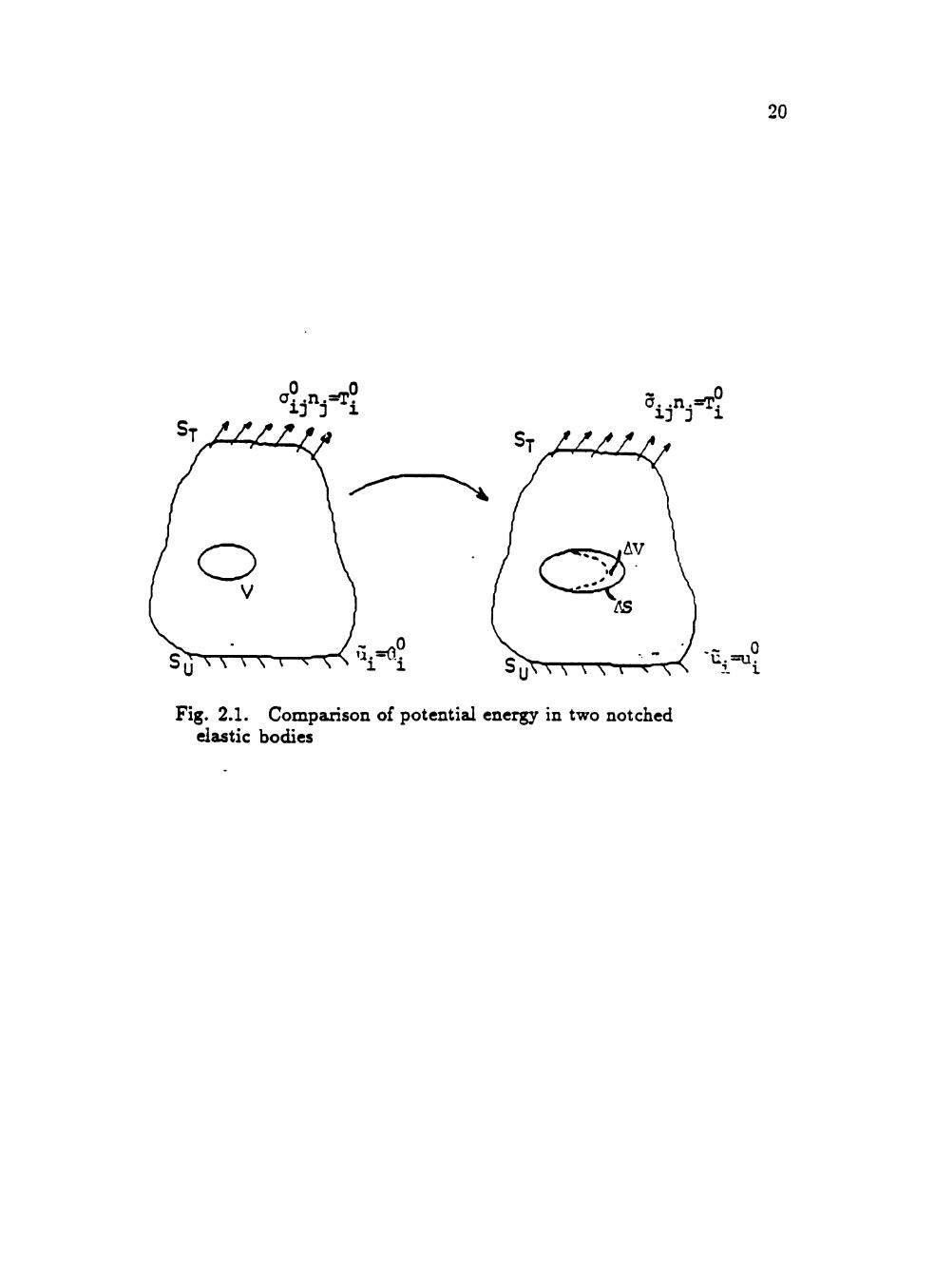
Suppose a body of volume V which contains a traction free void or notch is
loaded by surface tractions Tf on a portion of its boundary ST and by prescribed
displacements it° on Su- While holding the loading and displacements on ST and
Su fixed, the notch is enlarged by volume AV with surface AS (see Fig. 2.1).
Assume that the body forces acting on the material are negligible. If £°j represents
the state of strain in the initial state of the body before the void has enlarged,
then the potential energy of the initial state is given by
P" = lyV(el)dV - J^ ifuldS. 'ST
Here W is the strain energy density and is given by W = ^£' • 5 for a hnear
ela.stic material. Denote the displacements, strains, and stresses in the final state
by Uj = uj -h Atii, Cij — (j\^ ~ A<rij, and lij — £\- + Ae^j, respectively, and the
potential energy of the body in the final state by
P = P° + A P = / y^{£ii)dV - f T°u,dS. Jv-^v JST
Then the change in the potential energy from the initial to the final state is given
by
-AP = J W(4)(iV' - J^ TS'dS
- I W(f. )(iV - / TfuidS JV-£^V JST
= / W(c%)dV-l ;w(?i^)-w(£°)!<iv
^ I Jf(ui-u^)dS. (2.8) JST 'ST
By the Principle of Virtual Work
/ ((7°. + AcTij)njAuidS = f ( 4 + Aai^)A£x,dV. Jd{v-Avy ' Jv-Av ^
Since Aui = 0 on 5c;, A(T,jnj = 0 on 5 r , and the void is traction free,
/ (cr°- ^ AcT,j)njAuidS = f JfAuidS. ya(v--AV) ^ J ST
20
^IfA a. .n.=T.
Fig. 2.1. Comparison of potential energy in two notched elastic bodies

21
After substituting the above expression into (2.8), the change in potentieJ energy
may be written as
- A P = / W{£%)dV JAV ^
+ J (4 + A<ri,.)A£o- - [W(£?, - Ae.-,) - W(£»-)]dF JV—AV
Expanding J2, one has
- i[(<r?. + A<rij)(4 + A £ i ^ ) - 4 4 ] < i V
- I [<^A + ^<^iA + 4A^'i - A<ryA£,, - ^^ey,dV
= i.,,^A<r.,A.., + i<.A.<,-iA.,4<iV.
Betti's Reciprocal Theorem gives
/ <.A£i,(fy = / A^,,£°.ciV'. Jv-AV ^ JV-AV ^
Therefore
/2 = / -A(ri^A£ij(iV'. Jv-AV2
Another application of the Principle of Virtual Work yields
I2 = - I AcijnjAuidS 2 Jd{V-AV)
= - I AaijnjAuidS + - / AcTijnjAuidS - - / AaijnjAmdS. 2 JST 2 JSu ^ •'^•5
Again, recalling that Acij and Aui vanish on ST and Su, respectively, one finds
that
I2 = •- I Aa-ijnjAuidS 2 J AS

22
The notch is assumed to be traction free so aijnj = 0 and hence
12 = - - / (T^jnjAuidS. Z J AS
Therefore the change in potential energy of the body in which a notch has un
dergone an enlargement AV is given by
-AP = /^^W(4)<iV-i/^^<.n,Au..<f5.
In the case that the notch is a crack, AV = 0 and the change in potential energy
becomes
A P = - / a^-njAuidS. 2 J AS "' '
Let a denote the crack length in the initial state and a — Aa denote the crack
length in the final state. Let / (x i ,0~ , / ) denote a field quajitity associated with
a crack of length / where 0^ corresponds to hm^_o= /(xi,X2,/) . Then
A P = - / a'ij{xi,0^ya)nj[ui{xi,0~,a ~ Aa) — Ui{xi,Q~,a)]dS. 2 J AS
The unit normal to the surface of the crack, n^, is zero except when j = 2, so
rij == 712 = — 1 on the upper crack surface and nj = n2 = 1 on the lower crack
surface. In a mode III crack the only nonzero stresses are (T13 and a'23. Therefore
aijnj = — cr32. Thus
"^ /"a-i-Aa A P = -z -<7'32(xi,0^,a)[uJ(xi,0*,a-r Aa)-u^(xi ,0*,a)]<ixi
2 J a 2 /•o+Aa _ _
+ - / (T32(xi,0~,0,a)[uj(xi,0 , a - A a ) - U 3 ( x i , 0 " , a ) ] ( i x i .
2 Ja
If Xi varies between a and a -H Aa, with the crack tip corresponding to Xi = a.
then U3(xi,0'^,a + Aa) - U3(xi,0'=,a) = U3(xi,0*.a ^ Aa).
Therefore,
A P = — / <r32(xi,0,a)[u3(xi,0*,a - A a ) - U 3 ( i i . 0 .a-Aa)]dx^, 2 Ja
23
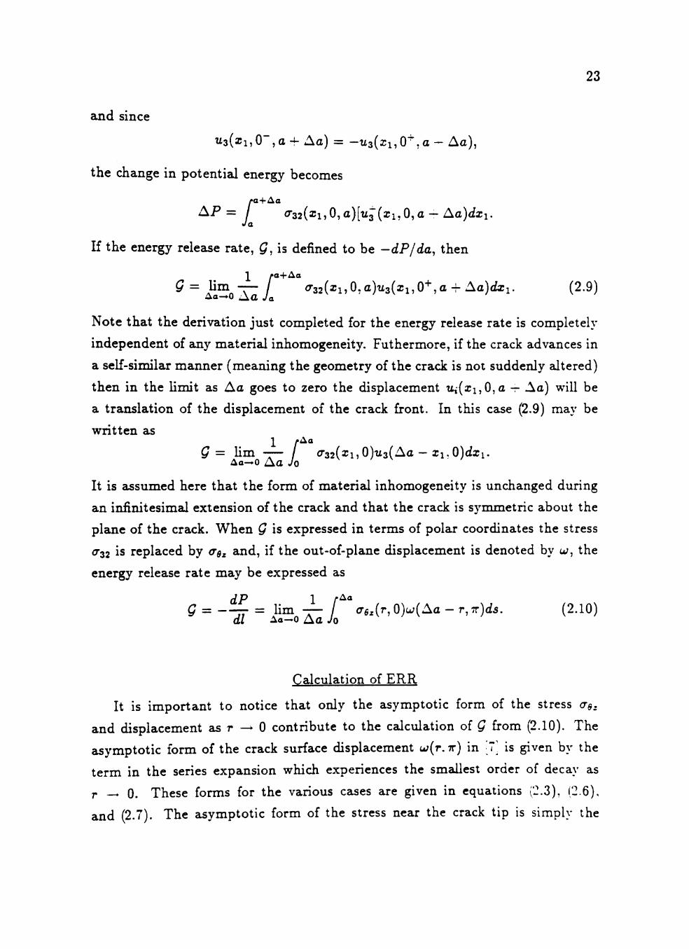
and since
^3(aJi,0",a-f Aa) = - U 3 ( x i , 0 ^ , a - Aa),
the change in potential energy becomes
ya+Aa A P = / o'32(xi,0,a)[tij(xi,0,a — Aa)<ixi.
Ja
If the energy release rate, Q, is defined to be -dP/da, then
\ ya+Aa
Q= lim -—- / «r32(xi,0.a)u3(xi,0"^,a + Aa)<ixi. (2.9) Aa->0 A a Ja
Note that the derivation just completed for the energy release rate is completely
independent of ajiy material inhomogeneity. Futhermore, if the crack advances in
a self-similar manner (meaning the geometry of the crack is not suddenly altered)
then in the limit as Aa goes to zero the displacement Ui(xi,0,a -r Aa) will be
a translation of the displacement of the crack front. In this case (2.9) may be
written as
Q= lim --— / o'32(xi,0)u3(Aa - xi.O)<ixi. Aa—0 Aa 0
It is assumed here that the form of material inhomogeneity is unchanged during
an infinitesimal extension of the crack and that the crack is symmetric about the
plane of the crack. When Q is expressed in terms of polar coordinates the stress
(732 is replaced by (TQ^ and, if the out-of-plane displacement is denoted by a;, the
energy release rate may be expressed as dP 1 t^°-
G = = lim -— / (rfi,(r,0)u;(Aa-r,7r)<i5. (2.10) dl Aa—o Aa Jo
Calculation of ERR
It is important to notice that only the asymptotic form of the stress (T^,
and displacement as r ^ 0 contribute to the calculation of Q from (2.10). The
asymptotic form of the crack surface displacement u;(r. r ) in • 7 is given by the
term in the series expansion which experiences the smallest order of decay as
r — 0. These forms for the various cases are given in equations (2.3), (2.6),
and (2.7). The asymptotic form of the stress near the crack tip is simply the

24
dominant singular term in the stress field. In case i), the asymptotic form of the
stress is the first term in the infinite sum in (2.1) since it is the only term which
contains a singular power of r. For case ii), the asymptotic form corresponds to
that term in (2.4) which exhibits a logarithimic singularity in r. In case iii) when
the stresses are bounded, the asymptotic form of the stress is the term in (2.1)
that is independent of r . By substituting these asymptotic forms into (2.10), the
energy release rate for each case is found:
case i)
where
case ii)
g = C. lim -i- fy^f-^H^)^^3^Y=^^¥^)ir, (2.11) Aa-*o AaJor^ 7*o
_ Sa-lrp (;;)
' 7 r V o ( l + / ? ^ ) i 2 - / 3 - V r : ^ l ^ '
1 r^» r Aa — r Aa — r i , , g = C , H m „ f - / l n ( - ) l n ( )( )UT, (2.12)
Ao-»0 A a Jo 7*0 7*0 TQ
where
c, = A^(-)'-25TT^ fj.0 To
case iii)
where
e = C, Um - ^ t°{^^-ly-^dr, (2.13) Aa—0 A a Jo 7*0
r - ^o^O/^=^/^ sin(7rVl - / ? ) ^ ' - fio Vo^ v / r ^ c o s 2 ( 7 r y r ^ ) '
Define the nondimensional quantities
and
r, r Aa 7 = — .s = — ,oa =
ro TQ TQ
Then for case i)
g = C,limi- 5^^' ^Sa-sY'^-^Us. (2.14) 6a—'0 oa Jo

25
where
Co = — 8 7^
7 r 2 ( l + / ? 2 ) ( 2 _ / 5 _ v T ^ - ^ ) 2 -
A simple integration shows that the integral in (2.13) is equal to zero, hence
the energy release rate for f < /3 < 1 vanishes. It is now shown that ^ = 0 for
case ii), /? = f. For 6a sufficiently small, \s* \ns\ < \6a^ ln6a\. Then
\T\ = I T - / ln(^a — 5)5* ln5 (i l oa 70 1 i r*°
< -T-|^a* ln^a| / \ln{6a - s)\ds da Jo
< —^6ahn6af''\n{6a-s)ds. (2.15) oa Jo
After integrating the right hand side, one finds
| / | < 6a* ln^a(ln^a - 1).
From an application of L'Hopitals rule it follows that lim^a—0- = 0 and hence
^ = 0 for /? = | . Thus the energy release rate is zero for 3 > ^.
The normalized energy release rate Q was calculated numerically using an
IMSL subroutine, and the results are illustrated in Fig. 2.2. With the exception of
very small values of/3, the effect of a decreasing rigidity is to significantly reduce
the ERR. Q is only illustrated for /? < .5 since Q = 0(10"^) for /? > .5. However,
it should be noted that ^ > 0 for /? < .75. Since Q represents the energy available
to the crack tip for propagating the crack, an effect of material softening near
the crack tip is similar to that provided by a yielded region: energy is dissipated
that would otherwise contribute to the fracture process. In conjunction with a
decreasing rigidity and ERR there is a marked change in the geometry of the crack
profile, as illustrated in Fig. 2.3, accompanied by a large displacement gradient
near the crack front. This is similar to behavior in highly deformable and certain
nonlinear materials in which it is difficult to transmit and concentrate energy
into the region where crack propagation may take place ([10. pp 149-150]). It
is also of interest to note that when 3 is very small, corresponding to a nearly
constant modulus except in a small zone about the crack tip (Fig. 2.4), and -v is
large enough so that the loaded crack may be regarded as being embedded in

26
applied load = IQ j->rQ "
y=yQ(r/r^)
SE:T.=. ' -^
Fig. 2.2. The normalized energy release rate

27
1 . 2 -
Fig. 2.3. Normalized crack surface displacement versus T/TQ (after [7])

28
Po
Fig. 2.4. The nondimensionalized shear modulus versus r/vg

29
the region determined by r^, then Q attains a value greater than that for a homo
geneous medium with modulus /XQ. For such a scenario, the failure to account for
a reduced rigidity near the crack tip could lead to \'alues of Q that underestimate
the actual energy release rate. However, if the size of the region where mate
rial softening occurs is much smaller than the length of the loaded crack, then
^ is a monotonically decreasing function of 3. This situation may be viewed
as modelling a small process zone at the crack tip where damage effects have
reduced rigidity and strength [11]. Within this context, the results indicate that
the incorporation of a process zone at the crack tip reduces the energy available
for crack propagation.
When a crack tip stress field does not display the conventional square root
singularity, as is the case for this problem, the usual notion of the SIF does not
lend itself to an obvious physical interpretation. For instance, in studies of cracks
propagating through a bimaterial interface where the stress singularity is of the
form r""', 0 < a < 1, employing the usual definition of the stress intensity
factor may result in a SIF of zero or infinity, depending on whether the power
of the singularity is less or greater than 1/2 (see, for example, [12!, [13]). This
phenomena is due to the fact that the stress state does not remain autonomous
as the crack advances through a material interface. In any case, the significance
of the coefficient of the singular part of the stress field as it relates to the crack
energetics is not always apparent. In the problem studied in this thesis, no simple
relationship exists between the stress coefficient of the dominant term near the
crack tip, say C(/3), and Q. Indeed it is a simple matter to show that C{,3) is
monotoniczdly increasing (decreasing) on the inter\'al 0 < /3 < 3/4 (3/4 < (3 <
1) , tending to infinity at 3/4. Of course, for /? = 0 one does recover the known
relationship that Q = 7rC2(0)/;io [14].

CHAPTER III
ALTERNATE FRACTURE THEORIES
Because the material inhomogeneity considered in this problem may result
in reduced values of the energy release rate, the initiation of crack growth may
be associated with a large applied load and attendant substantial inelastic de
formation or plastification at the crack tip. Moreover when /3 > 3/4 and the
energy release rate vanishes, Q does not provide zn applicable fracture criterion.
For these reasons it is of interest to investigate the effect of the material inhomo
geneity upon the plastic zones about the crack tip and to examine two alternative
fracture theories within the context of this problem.
In the case of antiplane strain the von Mises yield criterion may be written
in the form
<^L+^r, =^V. (3.1)
where cTy, is the yield stress in shear. This means that when the stress in the
body reaches this critical value, a linear relationship between stress and strain
is no longer valid and the material may begin to exhibit plastic deformation or
flow. More precisely, when yielding has occured deformations may be permanent
or large strains may result with Httle or no increase in appHed load. A convenient
method for visualizing the regions plastic effects may occur is to represent a^^ =
acTo, where ao is the applied load, and then construct a family of level curves
from (3.1) for various values of the parameter a. If only the singular terms of the
stresses given in (2.2) and (2.3) are utilized, the boundary of the plastic zone as
a function of 9 can be represented as
, . , ,4[cos2(g/2) - iVTTW - ay sin2(9/2)] ,u(2-0-./^» , . ,x
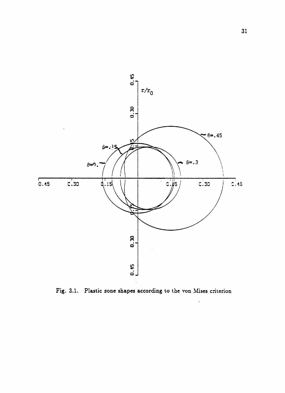
For the sake of illustration, plastic zones as predicted by (3.2) are plotted nondi-
mensionally as T/TQ in Fig. 3.1 for a = 3. For ^ = 0 the usual circular zone
associated with a mode III crack is obtained. When '^ is small and the eff'ects
30
LP
o r/r.
o
31
<re=.45
Fig. 3.1. Plastic zone shapes according to the von Mises criterion

32
of material inhomogeneity are very localized near the crack tip, the size of the
zone is actually reduced but its location is translated to a region ahead of the
crack. As (3 increases and matericd softening becomes more pronounced, the
plastic zones undergo a change in shape and a dramatic increase in size. It should
be noted that although the power of the singularity in the stresses decreases ^-ith
a reduced rigidity, it is the coefficient of the singular terms which contribute to
the enlarged zones of plasticity at the crack tip.
A fracture criterion which has been utilized in problems where the stresses
have an arbitrary power singularity is based on the maximum cleavage stress
theory (see [12],[9], and [15]). This criterion states that propagation will take
place in a direction 9 = 9^ for which the cleavage stress <rgz(7*p, ^c) is maximum
and equal to some critical value. The distance r^ is an experimentally determined
material constant related to the size of the process zone about the crack tip. The
normalized cleavage stress ae^la-Q is illustrated in Fig. 3.2 for T/TQ = 0.001. If
the direction of crack propagation is controlled by the maximum cleavage stress,
then for small (3 the crack path would be the crack axis, 5 = 0. However, with
decreasing rigidity, the stress distribution about the crack tip is nearly uniform
with no preferred direction. This effect becomes even more pronounced if a^^ is
evaluated at a sHghtly larger distance ahead of the crack. Experimental evidence
suggests that the path of crack propagation and local yielding do not coincide as
a crack always tends to bypass the yielded portion of a material [16i. This, in
conjunction with the results of Figures 3.1 and 3.2, suggests that a change in the
direction of crack propagation would occur in a matericd modeled by the shear
modulus adopted in this work. Such behavior was observed in solid propellants
which initially led to a consideration of this model [11].
Finally, the suitability of the strain energy density (SED) as a criterion for
determining failure or yielding for the crack problem considered will be discussed.
In this theory attention is focused on the strain energy density W when evaluated
along a fixed radius r" from the crack tip (see Fig 3.3). Yielding and fracture
are assumed to coincide with locations of maximum and minimum values of the
strain energy density, W^ax or Wmtn- Morever, the onset of yielding or fracture
is initiated when these extrema attain their respective critical values, say W'^ max

33
r/rQ=.001
Fig. 3.2. The angular variation of the normalized cleavage stress

34
Fig. 3.3. The region of reduced rigidity and the core region around the tip of a loaded crack

35
^^ ^min- For this problem, the strain energy density is given by
2fJL
UtiHzing equations (2.2- 2.3) and (2.5- 2.6), W may be calculated exactly. The
issue of approximating the SED by using only singular terms has been addressed
in several studies (see [17] and references contained therein). The conclusion
of these works-that higher order effects are essential in utilizing the SED-is
reinforced by comparing the first order strain energy density approximation with
the exact calculation of W. In particular the approximate SED always exhibits a
minimum in a direction given by 5 = 0** whereas the results here show that this
is not necessarily the case for the exact strain energy density.
Because of the variable shear modulus and the inclusion of higher effects in
calculating W, it is not possible to remove a "strain energy density factor" as in
[8]. Consequently the calculation of W is influenced by the choice of r' as well as
the length scales associated with reduced rigidity and the loaded crack, Vc and ro,
respectively. These choices compHcate the interpretation of results as predicted
by the strain energy density criterion. A normalized strain energy density
was evaluated for a variety of combinations of r ' and 7 = rc/r©. If one identifies
the parameter Vc with the radius r" of the "core region", on whose perimeter
the SED is to be evaluated [8], then r^ = r" and 7 < 1. For this scenario W
is illustrated in Fig. 3.4 with T'/TQ = 0.01 = 7. Fig. 3.5 shows the effect of the
size of the core region on the SED when the crack is embedded in the region
of reduced rigidity. The results illustrate that Wmin is not necessarily located
in the direction 9 = 0°, though this is more pronounced in Fig. 3.5. In general
one finds that as r^ and /3 increase, Wmax increases. For ductile materials W^^^
is always smaller than W^^^. This fact combined with the previous observation
suggests that with an increase in the extent and degree of materisd softening,
failure by material yielding would precede fracture initiation. In view of the
results displayed in Figures 3.4 and 3.5, it is not clear that one could predict.

36
Fig. 3.4. The norm alized strain energy density for V - r.
-ssssaeessSS

( a . ) f l , §-=.01 ^0
Cc.) Y=l, - -=1 ^0
Fig. 3.5. The effect of the size of the core region on the SED when the
crack is embedded in the region of reduced rigidity

38
with any degree of confidence, the direction of crack propagation based on the
strain energy density.
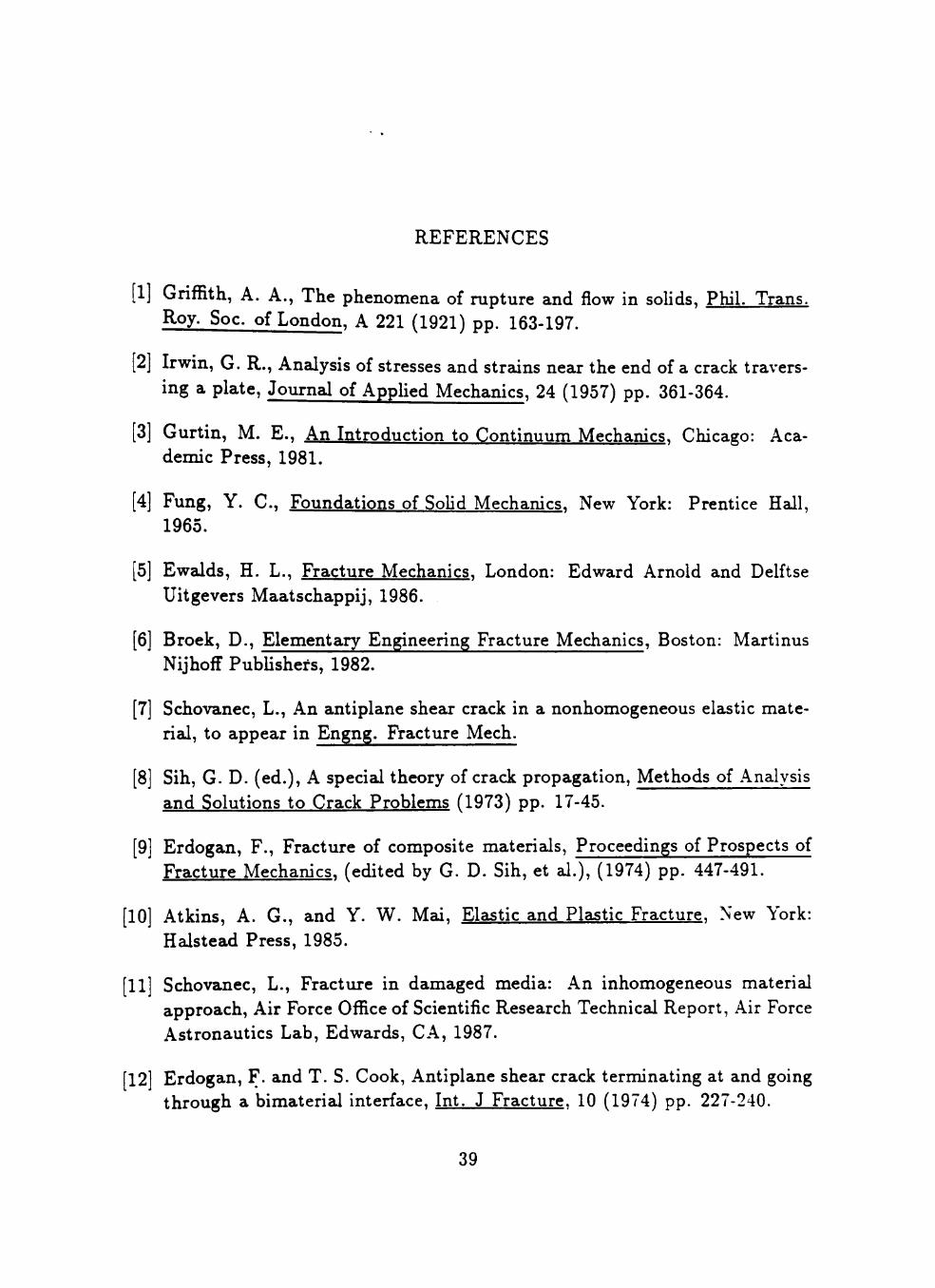
REFERENCES
[1] Griffith, A. A., The phenomena of rupture and flow in soHds, Phil. Trans. Roy. Soc. of London, A 221 (1921) pp. 163-197.
[2] Irwin, G. R., Analysis of stresses and strzdns near the end of a crack traversing a plate. Journal of Applied Mechanics, 24 (1957) pp. 361-364.
[3] Gurtin, M. E., An Introduction to Continuum Mechanics. Chicago: Academic Press, 1981.
[4] Fung, Y. C , Foundations of Solid Mechanics. New York: Prentice Hall, 1965.
[5] Ewalds, H. L., Fracture Mechanics. London: Edward Arnold and Delftse Uitgevers Maatschappij, 1986.
[6] Broek, D., Elementary Engineering Fracture Mechanics, Boston: Martinus Nijhoff PubUshers, 1982.
[7] Schovanec, L., An ajitiplane shear crack in a nonhomogeneous elastic material, to appear in Engng. Fracture Mech.
[8] Sih, G. D. (ed.), A special theory of crack propagation. Methods of Analysis and Solutions to Crack Problems (1973) pp. 17-45.
[9] Erdogan, F., Fracture of composite materials. Proceedings of Prospects of Fracture Mechanics, (edited by G. D. Sih, et al.), (1974) pp. 447-491.
[10] Atkins, A. G., and Y. W. Mai, Elastic and Plastic Fracture. New York: Halstead Press, 1985.
[11] Schovanec, L., Fracture in damaged media: An inhomogeneous material approach. Air Force Office of Scientific Research Technical Report, Air Force Astronautics Lab, Edwards, CA, 1987.
[12] Erdogan, F. and T. S. Cook, Antiplane shear crack terminating at and going through a bimaterial interface. Int. J Fracture. 10 (1974) pp. 227-240.
39

40
[13] Erdogan F., and V. Biricikoglu, Two bonded half planes with a crack going through the interface. Int. J. Engng. Science, 11 (1973) pp. 745-766.
[14] Sih, G. C , and H. Leibowitz, Mathematical theories of brittle fracture. Fracture: An Advanr^H Treatise, (edited by H. Leibowitz), 2 (1968), pp. 68-188.
[15] Fenner, D. N., Stress singularities in composite materials with an arbitrarily oriented crack meeting an interface. Int. J. Fracture. 12 (1976) pp. 705-721.
[16] Sih, G. C. (ed.), Elastodynamic crack problems, Amsterdam: Noordhoff Leyden, 1977.
[17] Smith, R. N. L., Second-order terms and strain energy density for the angled crack problem, Engng. Fracture Mech., 26 (1987) pp. 463-469.
PERMISSION TO COPY
In presenting this thesis in partial fulfillment of the
requirements for a master's degree at Texas Tech University, I agree
that the Library and my major department shall make it freely avail
able for research purposes. Permission to copy this thesis for
scholarly purposes may be granted by the Director of the Library or
my major professor. It is understood that any copying or publication
of this thesis for financial gain shall not be allowed without my
further written permission and that any user may be liable for copy
right infringement.
Disagree (Permission not granted) Agree (Permission granted)
Student's signature <^M^ TcM J ^ Student's signature
^^i'<VVk^^»>4.
Date 7-«l^ - JV
Date