Embed Size (px)
Citation preview
November 2002, ver. 3.0 Application Note 214
Using the DSP Blocksin Stratix & Stratix GX
Devices
Introduction Traditionally, designers had to make a trade-off between the flexibility of off-the-shelf digital signal processors and the performance of custom-built devices. Altera® Stratix™ and Stratix GX devices eliminate the need for this trade-off by providing exceptional performance combined with the flexibility of programmable logic devices (PLDs). Stratix and Stratix GX devices have dedicated digital signal processing (DSP) blocks, which have high-speed parallel processing capabilities, that are optimized for DSP applications. DSP blocks are ideal for implementing DSP applications that need high data throughput.
The most commonly used DSP functions are finite impulse response (FIR) filters, complex FIR filters, infinite impulse response (IIR) filters, fast Fourier transform (FFT) functions, discrete cosine transform (DCT) functions, and correlators. These functions are the building blocks for more complex systems such as wideband code division multiple access (W-CDMA) basestations, voice over Internet protocol (VoIP), and high- definition television (HDTV).
Although these functions are complex, they all use similar building blocks such as multiply-adders and multiply-accumulators. Stratix and Stratix GX DSP blocks combine five arithmetic operations—multiplication, addition, subtraction, accumulation, and summation—to meet the requirements of complex functions and to provide improved performance.
This application note describes the Stratix and Stratix GX DSP blocks, and explains how you can use them to implement high-performance DSP functions. It addresses the following topics:
■ Architecture■ Operational Modes■ Software Support■ Quartus II DSP Megafunctions
f Refer to the Stratix Programmable Logic Device Family Data Sheet and the Stratix GX FPGA Family Data Sheet for more information on Stratix and Stratix GX devices, respectively.
Altera Corporation 1
AN-214-3.0

AN 214: Using the DSP Blocks in Stratix & Stratix GX Devices
DSP Block Overview
Each Stratix and Stratix GX device has two columns of DSP blocks that efficiently implement multiplication, multiply accumulate (MAC), and filtering functions. Figure 1 shows one of the columns with surrounding LAB rows. You can configure each DSP block to support:
■ Eight 9 × 9 bit multipliers■ Four 18 × 18 bit multipliers■ One 36 × 36 bit multiplier
Figure 1. DSP Blocks Arranged in Columns
DSP BlockColumn
8 LABRows
DSP Block
2 Altera Corporation

AN 214: Using the DSP Blocks in Stratix & Stratix GX Devices
The multipliers can then feed an adder or an accumulator block, depending on the DSP block operational mode. Additionally, you can use the DSP block input registers as shift registers to implement applications such as FIR filters efficiently. The number of DSP blocks per column increases with device density. Tables 1 and 2 describe the number of DSP blocks in each Stratix and Stratix GX device, respectively, and the multipliers that you can implement.
Note to Tables 1 and 2:(1) Each device has either the number of 9 ⋅ 9-, 18 ⋅ 18-, or 36 ⋅ 36-bit multipliers shown. The total number of multipliers
for each device is not the sum of all the multipliers.
Figure 2 shows the DSP block operating as an 18 × 18 multiplier.
Table 1. Number of DSP Blocks in Stratix Devices Note (1)
Device DSP Blocks 9 × 9 Multipliers 18 × 18 Multipliers 36 × 36 Multipliers
EP1S10 6 48 24 6
EP1S20 10 80 40 10
EP1S25 10 80 40 10
EP1S30 12 96 48 12
EP1S40 14 112 56 14
EP1S60 18 144 72 18
EP1S80 22 176 88 22
EP1S120 28 224 112 28
Table 2. Number of DSP Blocks in Stratix GX Devices Note (1)
Device DSP Blocks 9 × 9 Multipliers 18 × 18 Multipliers 36 × 36 Multipliers
EP1SGX10C 6 48 24 6
EP1SGX10D 6 48 24 6
EP1SGX25C 10 80 40 10
EP1SGX25D 10 80 40 10
EP1SGX25F 10 80 40 10
EP1SGX40D 14 112 56 14
EP1SGX40G 14 112 56 14
Altera Corporation 3

AN 214: Using the DSP Blocks in Stratix & Stratix GX Devices
Figure 2. DSP Block in 18 × 18 Mode
Adder/Subtractor/
Accumulator
Adder/Subtractor/
Accumulator
Adder
Multiplier BlockOutput
RegisterPRN
CLRN
D Q
ENA
PRN
CLRN
D Q
ENA
PRN
CLRN
D Q
ENAPRN
CLRN
D Q
ENA
PRN
CLRN
D Q
ENA
PRN
CLRN
D Q
ENA
PRN
CLRN
D Q
ENA
PRN
CLRN
D Q
ENA
PRN
CLRN
D Q
ENA
PRN
CLRN
D Q
ENA
PRN
CLRN
D Q
ENA
PRN
CLRN
D Q
ENA
Optional Serial Shift RegisterInputs from Previous DSP Block
From the Row Interface Block
SummationBlock
PipelineRegister
Adder Output Block
4 Altera Corporation

AN 214: Using the DSP Blocks in Stratix & Stratix GX Devices
Architecture The DSP block consists of the following elements:
■ A multiplier block■ An adder/subtractor/accumulator block■ A summation block■ An output interface■ Output registers■ Routing and control signals
Multiplier Block
Each multiplier block has input registers, a multiplier stage, and a pipeline register. See Figure 3.
Figure 3. Multiplier Block Architecture
CLRN
D Q
ENA
Data A
Data B
Data Outto AdderBlocks
shiftoutb shiftouta
shiftinashiftinb
aclr[3..0]clock[3..0]
ena[3..0]
signasignb
CLRN
D Q
ENA
CLRN
D Q
ENA
Altera Corporation 5

AN 214: Using the DSP Blocks in Stratix & Stratix GX Devices
Input Registers
Each operand feeds an input register or the multiplier directly. The DSP block has the following signals (one of each controls every input and output register):
■ clock[3..0]■ ena[3..0]■ aclr[3..0]
The input registers feed the multiplier and drive two dedicated shift output lines, shiftouta and shiftoutb. The shift outputs from one multiplier block directly feed the adjacent multiplier block in the same DSP block (or the next DSP block), as shown in Figure 4 on page 7, to form a shift register chain. This chain can terminate in any block, i.e., you can create any length of shift register chain up to 224 registers. A shift register is useful in DSP applications such as FIR filters. When implementing 9 × 9 and 18 × 18 multipliers, you do not need external logic to create the shift register chain because the input shift registers are internal to the DSP block. This implementation greatly reduces the required LE count and routing resources, and produces repeatable timing.
6 Altera Corporation

AN 214: Using the DSP Blocks in Stratix & Stratix GX Devices
Figure 4. Shift Register Chain
CLRN
D Q
ENA
Data A
Data B
A[n] × B[n]
CLRN
D Q
ENA
CLRN
D Q
ENA
CLRN
D Q
ENA
shiftoutashiftoutb
A[n - 1] × B[n - 1]
CLRN
D Q
ENA
CLRN
D Q
ENA
CLRN
D Q
ENA
shiftoutashiftoutb
A[n - 2] × B[n - 2]
CLRN
D Q
ENA
CLRN
D Q
ENA
DSP Block 0
DSP Block 1
shiftoutashiftoutb
Altera Corporation 7

AN 214: Using the DSP Blocks in Stratix & Stratix GX Devices
Multiplier Stage
The multiplier stage supports 9 × 9, 18 × 18, or 36 × 36 multiplication. (The multiplier stage also support smaller multipliers. Refer to “Operational Modes” on page 18 for details.) Based on the data width, a single DSP block can perform many multiplications in parallel.
The multiplier operands can be signed or unsigned numbers. Two signals, signa and signb, indicate the representation of the two operands. For example, a logic 1 on the signa signal indicates that data A is a signed number; a logic 0 indicates an unsigned number. The result of the multiplication is signed if any one of the operands is a signed number, as shown in Table 3.
The signa and signb signals affect the entire DSP block. Therefore, all of the data A inputs feeding the same DSP block must have the same sign representation. Similarly, all of the data B inputs feeding the same DSP block must have the same sign representation. The multiplier offers full precision regardless of the sign representation.
1 By default, the Altera Quartus® II software sets the multiplier to perform unsigned multiplication when the signa and signb signals are not used.
Pipeline Registers
The output from the multiplier can feed a pipeline register or be bypassed. You can use pipeline registers for any multiplier size; pipelining is useful for increasing the DSP block performance, particularly when using subsequent adder stanges.
1 In the DSP block, pipelining improves the performance of 36 × 36 multipliers. For 18 × 18 multipliers and smaller, pipelining adds latency but does not improve performance.
Table 3. Multiplier Signed Representation
Data A Data B Result
Unsigned Unsigned Unsigned
Unsigned Signed Signed
Signed Unsigned Signed
Signed Signed Signed
8 Altera Corporation

AN 214: Using the DSP Blocks in Stratix & Stratix GX Devices
Adder/Output Block
The adder/output block has the following elements (See Figure 5 on page 10):
■ An adder/subtractor/accumulator block■ A summation block■ An output select multiplexer■ Output registers
You can configure the adder/output block as:
■ A pure output interface■ An accumulator■ A simple one-level adder■ A two-level adder with dynamic addition/subtraction control on the
first-level adder■ The final stage of a 36-bit multiplier
The output select multiplexer sets the output of the DSP block. You can register the adder/output block’s output using the output registers.
1 You cannot use the adder/output block independently from the multiplier.
Altera Corporation 9

AN 214: Using the DSP Blocks in Stratix & Stratix GX Devices
Figure 5. Adder/Output Block
Adder/Subtractor/Accumulator Block
The adder/subtractor/accumulator is the first level of the adder/output block. You can configure the block as an accumulator or as an adder/subtractor.
Adder/Subtractor/
Accumulator 0
Adder
Result A
Result B
Result C
Result D
addnsub1
accum_sload0
addnsub3
signa
signb
accum_sload1
Accumulator Feedback
Accumulator Feedback
overflow0
Adder/Subtractor/
Accumulator 1
Output SelectMultiplexer
OutputRegisters
overflow1
10 Altera Corporation

AN 214: Using the DSP Blocks in Stratix & Stratix GX Devices
Accumulator
When the adder/subtractor/accumulator is configured as an accumulator, the output of the adder/output block feeds back to the accumulator as shown in Figure 5 on page 10. You can use the accum_sload[1..0] signals to clear the accumulator asynchronously. This action is not the same as resetting the output registers. You can clear the accumulation and begin a new one without losing any clock cycles.
The overflow signal goes high on the positive edge of the clock when the accumulator overflows or underflows. In the next clock cycle, however, the overflow signal resets to zero even though an overflow (or underflow) occurred in the previous clock cycle. Use a latch to preserve the overflow condition indefinitely (until the latch is cleared).
Adder/Subtractor
The addnsub[1..0] signals select addition or subtraction: high for addition and low for subtraction. You can control the addnsub[1..0] signals using external logic; therefore, the first-level block can switch from an adder to a subtractor dynamically, simply by changing the addnsub[1..0] signals. If the first stage is configured as a subtractor, the output is A - B and C - D.
The adder/subtractor also uses two signals, signa and signb, like the multiplier block. These signals indicate the sign representation of both operands together. You can register the signals with a latency of 1 or 2 clock cycles.
Summation Block
The output from the adder/subtractor feeds to an optional summation block, which is an adder block that sums the outputs of the adder/subtractor. The summation block is important in applications such as FIR filters.
Output Select Multiplexer
The outputs from the various elements of the adder/output block are routed through an output select multiplexer. Based on the DSP block operational mode, the outputs of the multiplier block, adder/subtractor/accumulator, or summation block feed straight to the output, bypassing the remaining blocks in the DSP block.
1 The output select multiplier configuration is configured automatically by software.
Altera Corporation 11

AN 214: Using the DSP Blocks in Stratix & Stratix GX Devices
Output Registers
You can use the output registers to register the DSP block output. Like the input registers, the output registers are controlled by the four clock[3..0], aclr[3..0], and ena[3..0] signals. You can use the output registers in any DSP block operational mode.
1 The output registers form part of the accumulator in the multiply-accumulate mode.
Routing Structure & Control Signals
This section describes the interface between the DSP blocks and the row interface blocks. It also describes how the DSP block generates control signals and how the signals route from the row interface to the DSP block.
DSP Block Interface
The DSP blocks are organized in columns, which provides efficient horizontal communication between the blocks and the column-based memory blocks. The DSP block communicates with other parts of the device through an input and output interface. Each DSP block, including the input and output interface, is 8 logic array blocks (LABs) long.
The DSP block and row interface blocks consist of eight blocks that connect to eight adjacent LAB rows on the left and right. Each of the eight blocks has two regions: right and left, one per row. The DSP block receives 144 data input signals and 18 control signals for a total of 162 input signals. This block drives out 144 data output signals; 2 of the data signals can be used as overflow signals (overflow). Figure 6 provides an overview of the DSP block and its interface to adjacent LABs.
Figure 6. DSP Block Interface to Adjacent LABs
1448 LABRows
RowInterfaces
0 through 7
DSPBlock
8 LABRows
DSP Block & Row Interface
144
18
Data
Control
162
DSP BlockInput Interface
DSP BlockOutput Interface
12 Altera Corporation

AN 214: Using the DSP Blocks in Stratix & Stratix GX Devices
Input Interface
The DSP block input interface has 162 input signals from adjacent LABs; 18 data signals per row and 18 control signals per block.
Output Interface
The DSP block output interface drives 144 outputs to adjacent LABs, 18 signals per row from 8 rows.
Because the DSP block outputs communicate horizontally, and because each DSP block row has more outputs than an LAB (18 from the DSP block compared to 10 from an LAB), the DSP block has double the number of row channel drivers compared to an LAB. The DSP block has the same number of row channels, but the row channels are staggered as if there were two LABs within each block. The DSP blocks have the same number of column channels as LABs because DSP blocks communicate primarily through row channels.
Row Interface Block
Each row interface block connects to the DSP block row structure with 21 signals. Because each DSP block has eight row interface blocks, this block receives 162 signals from the eight row interfaces. Of the 162 signals, 144 are data inputs and 18 are control signals. Figure 7 on page 14 shows one row block within the DSP block.
Altera Corporation 13

AN 214: Using the DSP Blocks in Stratix & Stratix GX Devices
Figure 7. DSP Row Interface Block
Control Signals in the Row Interface Block
The DSP block has a set of input registers, a pipeline register, and an output register. Each register is grouped in banks that share the same clock and clear resources:
■ 1- to 9-bit banks for the input register■ 1- to 18-bit banks for the pipeline register■ 18 bits for the output register
LAB LAB
Row InterfaceBlock
DSP BlockRow Structure
10
[17..0][17..0]
DSP Block toLAB Row InterfaceBlock Interconnect Region
18 Inputs per Row 18 Outputs per Row
R4 and R8 Interconnects
C4 and C8 Interconnects
DirectLink Interconnectfrom Adjacent LAB
Nine DirectLink Outputsto Adjacent LABs
DirectLink Interconnectfrom Adjacent LAB
1818
9
10
3Control
9
18
14 Altera Corporation

AN 214: Using the DSP Blocks in Stratix & Stratix GX Devices
The row interface block generates the control signals and routes them to the DSP block. Each DSP block has 18 control signals:
■ Four clock signals (clock[3..0]), which are available to each bank of DSP blocks
■ Four clear signals (aclr[3..0]), which are available to each bank of DSP blocks
■ Four clock enable signals (ena[3..0]), which the whole DSP block can use
■ signa and signb, which are specific to each DSP block■ addnsub[1..0] signals■ accum_sload[1..0] signals
The signa, signb, and addnsub[1..0], accum_sload[1..0] signals have independent clocks and clears and can be registered individually. When each 18 × 18 multiplier in the DSP block splits in half to two 9 × 9 multipliers, each 9 × 9 multiplier has independent control signals. Figure 8 shows the DSP block row interface and shows how it generates the data and control signals.
Figure 8. DSP Block Row Interface
DSP Row 1
DSP Row 2
DSP Row 3
DSP Row 4
DSP Row 5
DSP Row 6
DSP Row 7
DSP Row 8
DSP Block Row Interface
InputRegisters
DSPBlock
Bit 0
Bit 1
Bit 2
Bit 3
Bit 4
Bit 5
Bit 6
Bit 7
Bit 8
DSP Row
Bit 9
Bit 10
Bit 11
Bit 12
Bit 13
Bit 14
Bit 15
Bit 16
Bit 17
DSP Row
21 Signals for Data to Input
Register
DSP RowUnit Control
Block
3
30 LocalInterconnect
Signals
LABRow
Clocks
Detail of 1 DSP Row
Altera Corporation 15

AN 214: Using the DSP Blocks in Stratix & Stratix GX Devices
The DSP block interface generates the clock signals from LAB row clocks or the local interconnect. The clear signals are generated from the local interconnects within each DSP block row interface or from LAB row clocks. The four clock enable signals are generated from the 30 local interconnects from the same LAB rows that generate the clock signals. The clock enable is paired with the clock because the enable logic is implemented at the interface. Figure 9 shows the signal distribution within the row interface block.
Figure 9. DSP Block Row Interface Signal Distribution
18 × 18 Multiplier
A1
B1
18
18
18
18Row 1
Row 2
18 × 18 Multiplier
A4
B4
18
18
18
18Row 7
Row 8
44
418
clock[3..0]
aclr[3..0]ena[3..0]
data[17..0]
InputRegisters
18-Bit Data Routedfrom 30 LocalInterconnects
Four Clock EnableSignals Routed from30 Local Interconnects
Four Clear SignalsRouted from 30 LocalInterconnects or LABRow Clock
Four Clock SignalsRouted from LAB Row Clock or LocalInterconnect
16 Altera Corporation

AN 214: Using the DSP Blocks in Stratix & Stratix GX Devices
Each row block provides 18 bits of data to the multiplier (i.e., one of the operands to the multiplier), which are routed through the 30 local interconnects within each DSP row interface block. Any signal in the device can be the source of the 18-bit multiplier data, by connecting to the local row interconnect through any row or column.
Each control signal routes through one of the eight rows of the DSP block. Table 4 shows the 18 control signals and the row to which each one routes.
Input/Output Data Interface Routing
The 30 local interconnects generate the 18 inputs to the row interface blocks. The 21 outputs of the row interface block are the inputs to the DSP row block (see Figure 7 on page 14).
Table 4. Control Signals in DSP block
Signal Name Row Description
signa 1 DSP block-wide signed and unsigned control signals for all multipliers. The multiplier outputs are unsigned only if both signa and signb are low.
signb 6
addnsub1 3 Controls addition or subtraction of the two one-level adders. The addnsub0 signal controls the top two one-level adders; the addnsub1 signal controls the bottom two one-level adders. A high indicates addition; a low indicates subtraction.
addnsub3 7
accum_sload0 2 Resets the feedback input to the accumulator. The signal asynchronously clears the accumulator and allows new accumulation to begin without losing any clock cycles. The accum_sload0 controls the top two one-level adders, and the accum_sload1 controls the bottom two one-level adders. A low is for normal accumulation operations and a high is for zeroing the accumulator.
accum_sload1 7
clock0 3 DSP block-wide clock signals.
clock1 4
clock2 5
clock3 6
aclr0 1 DSP block-wide clear signals.
aclr1 4
aclr2 5
aclr3 7
ena[3..0] Same Rows as the Clock Signals
DSP block-wide clock enable signals.
Altera Corporation 17

AN 214: Using the DSP Blocks in Stratix & Stratix GX Devices
The row interface block has DirectLink™ connections that connect the DSP block input or output signals to the left and right adjacent LABs at each row. (The DirectLink connections provide interconnects between LABs and adjacent blocks.) The DirectLink connection reduces the use of row and column interconnects, providing higher performance and flexibility.
Each row interface block receives 10 DirectLink connections from the right adjacent LABs and 10 from the left adjacent LABs. Additionally, the row interface block receives signals from the DSP block, making a total of 30 local interconnects for each row interface block. All of the row and column resources within the DSP block can access this interconnect region (see Figure 7 on page 14).
A DSP block has nine outputs that drive the right adjacent LAB and nine that drive the left adjacent LAB through DirectLink interconnects. All 18 outputs drive any row or column.
Operational Modes
You can use the DSP block in one of four operational modes, depending on your application needs (see Table 4). The Quartus II software has built-in megafunctions that you can use to control the mode. After you have made your parameter settings using the megafunction’s MegaWizard® Plug-In, the Quartus II software automatically configures the DSP block.
Table 5. DSP Block Operational Modes
Mode 9 × 9 18 × 18 36 × 36
Simple multiplier Eight multipliers with eight product outputs
Four multipliers with four product outputs
One multiplier
Multiply accumulator Two 34-bit multiply-accumulate blocks
Two 52-bit multiply-accumulate blocks
–
Two-multiplier adder Four two-multiplier adders Two two-multiplier adders –
Four-multiplier adder Two four-multiplier adders One four-multiplier adder –
18 Altera Corporation

AN 214: Using the DSP Blocks in Stratix & Stratix GX Devices
Altera Corporation 19
Simple Multiplier Mode
In simple multiplier mode, the DSP block performs individual multiplication operations for general-purpose multipliers and for applications such as equalizer coefficient updates that require many individual multiplication operations.
9- & 18-Bit Multipliers
You can configure each DSP block multiplier for 9 or 18 bits. A single DSP block can support up to 8 individual 9-bit or smaller multipliers, or up to 4 individual multipliers with operand widths between 10- and 18-bits. Figure 10 shows the simple multiplier mode.
Figure 10. Simple Multiplier Mode
The multiplier operands can accept signed integers, unsigned integers, or a combination. The signa and signb signals are dynamic and can be registered in the DSP block. Additionally, you can register the multiplier inputs and results independently. Pipelining the result, using the pipeline registers in the block, increases the performance of the DSP block.
CLRN
D Q
ENA
A
CLRN
D Q
ENA
CLRN
D Q
ENA
A
B
shiftoutb shiftouta
signb
signa
Adder Output Block
AN 214: Using the DSP Blocks in Stratix & Stratix GX Devices
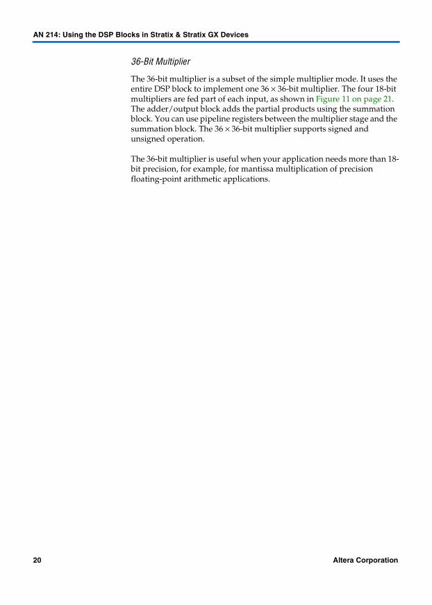
36-Bit Multiplier
The 36-bit multiplier is a subset of the simple multiplier mode. It uses the entire DSP block to implement one 36 × 36-bit multiplier. The four 18-bit multipliers are fed part of each input, as shown in Figure 11 on page 21. The adder/output block adds the partial products using the summation block. You can use pipeline registers between the multiplier stage and the summation block. The 36 × 36-bit multiplier supports signed and unsigned operation.
The 36-bit multiplier is useful when your application needs more than 18-bit precision, for example, for mantissa multiplication of precision floating-point arithmetic applications.
20 Altera Corporation

AN 214: Using the DSP Blocks in Stratix & Stratix GX Devices
Figure 11. 36-Bit Multiplier
CLRN
D Q
ENA
A[17..0]
A[17..0]
B[17..0]
B[17..0]
A[35..18]
A[35..18]
B[35..18]
B[35..18]
signasignb
CLRN
D Q
ENA
CLRN
D Q
ENA
CLRN
D Q
ENA
CLRN
D Q
ENA
CLRN
D Q
ENA
CLRN
D Q
ENA
CLRN
D Q
ENA
CLRN
D Q
ENA
CLRN
D Q
ENA
CLRN
D Q
ENA
CLRN
D Q
ENA
CLRN
D Q
ENA
Data Out
PartialProduct
SummationBlock
A
B
C
D
Altera Corporation 21

AN 214: Using the DSP Blocks in Stratix & Stratix GX Devices
Multiply Accumulator Mode
In multiply accumulator mode, the output of the multiplier stage feeds the adder/output block, which is configured as an accumulator or subtractor (see Figure 12). You can implement up to two independent 18-bit multiply accumulators in one DSP block. The Quartus II software implements smaller multiplier-accumulators by tying the unused low-order bits of an 18-bit multiplier to ground.
Figure 12. Multiply Accumulator Mode
Note to Figure 12:(1) The signa and signb signals are the same in the multiplier stage and the adder/output block.
CLRN
D Q
ENA
CLRN
D Q
ENA
Data A
Data B
Data Out
overflow
shiftoutb shiftouta
shiftinashiftinb
aclrclock
ena
signa (1)signb (1)
CLRN
D Q
ENA
CLRN
D Q
ENA
Accumulator
addnsub1
signa
signb
accum_sload1
CLRN
D Q
ENA
22 Altera Corporation

AN 214: Using the DSP Blocks in Stratix & Stratix GX Devices
The multiply accumulator output can be up to 52 bits wide for a maximum 36-bit result with 16-bits of accumulation. In this mode, the DSP block uses output registers and the accum_sload and overflow signals. The accum_sload[1..0] signal synchronously loads the multiplier result to the accumulator output. This signal can be unregistered or registered once or twice. The DSP block can then begin a new accumulation without losing any clock cycles. The overflow signal indicates an overflow or underflow in the accumulator. This signal is cleared for the next accumulation cycle, and you can use an external latch to preserve the signal. You can use the addnsub[1..0] signals to perform accumulation or subtraction dynamically.
1 If you want to use DSP blocks and your design only has an accumulator, you can use a multiply by one followed by an accumulator to force the software to implement the logic in the DSP block.
Two-Multiplier Adder
The two-multiplier adder mode uses the adder/output block to add or subtract the outputs of the multiplier block, which is useful for applications such as FFT functions and complex FIR filters. Additionally, in this mode, the DSP block outputs two sums or differences for multipliers up to 18 bits, or 4 sums or differences for 9-bit or smaller multipliers. A single DSP block can implement one 18 × 18-bit complex multiplier or two 9 × 9-bit complex multipliers.
A complex multiplication can be written as:
(a + jb) × (c + jd) = (a × c – b × d) + j × (a × d + b × c)
In this mode, a single DSP block calculates the real part (a × c – b × d) using one adder/subtractor/accumulator and the imaginary part (a × d + b × c) using another adder/subtractor/accumulator for data up to 18 bits. Figure 13 shows an 18-bit complex multiplication. For data widths up to 9 bits, the DSP block can perform two complex multiplications using four one-level adders. Resources outside of the DSP block route each input to the two multiplier inputs.
1 You can only use the adder block if it follows multiplication operations.
Altera Corporation 23

AN 214: Using the DSP Blocks in Stratix & Stratix GX Devices
Figure 13. Complex Multiplier Implemented Using Two-Multiplier Adder Mode
Four-Multiplier Adder Mode
In the four-multiplier adder mode, which you can use for 1-dimensional and 2-dimensional filtering applications, the DSP block adds the results of two adder/subtractor/accumulators in a final stage (the summation block).
1 You can only use the adder block if it follows multiplication operations.
9- & 18-Bit Summation Blocks
A single DSP block can implement one 18 × 18 or two 9 × 9 summation blocks (see Figure 14 on page 25). The multiplier product widths must be the same size.
Subtractor
36
36
18
18
18
37
A
C
B
D
18
A × C - B × D(Real Part)
Adder
36
36
18
18
37
A
D
B
C
A × D + B × C(Imaginary Part)
18
18
18
DSP Block
24 Altera Corporation

AN 214: Using the DSP Blocks in Stratix & Stratix GX Devices
Figure 14. Four-Multiplier Adder Mode
CLRN
D QENA
Data A
Data B
shiftinb
shiftinaaclr
clockena
signasignb
CLRN
D Q
ENA
CLRN
D Q
ENA
CLRN
D QENA
Data A
Data B
CLRN
D Q
ENA
CLRN
D Q
ENA
Adder/Subtractor
CLRN
D QENA
Data A
Data B
CLRN
D Q
ENA
CLRN
D Q
ENA
CLRN
D QENA
Data A
Data B
shiftoutb shiftouta
CLRN
D Q
ENA
CLRN
D Q
ENA
Adder/Subtractor
addnsub0signasignb CLRN
D QENA
Data Out
addnsub1
Adder
Altera Corporation 25
AN 214: Using the DSP Blocks in Stratix & Stratix GX Devices
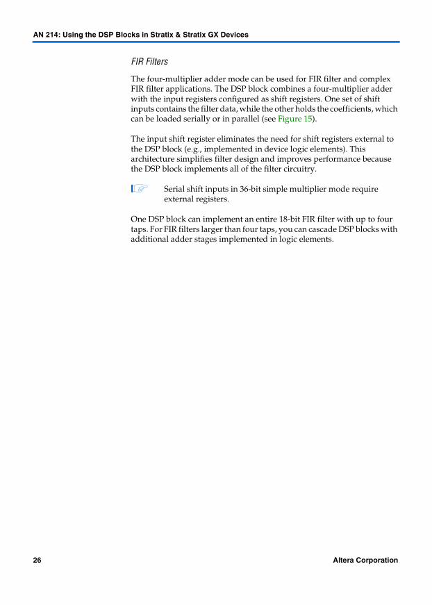
FIR Filters
The four-multiplier adder mode can be used for FIR filter and complex FIR filter applications. The DSP block combines a four-multiplier adder with the input registers configured as shift registers. One set of shift inputs contains the filter data, while the other holds the coefficients, which can be loaded serially or in parallel (see Figure 15).
The input shift register eliminates the need for shift registers external to the DSP block (e.g., implemented in device logic elements). This architecture simplifies filter design and improves performance because the DSP block implements all of the filter circuitry.
1 Serial shift inputs in 36-bit simple multiplier mode require external registers.
One DSP block can implement an entire 18-bit FIR filter with up to four taps. For FIR filters larger than four taps, you can cascade DSP blocks with additional adder stages implemented in logic elements.
26 Altera Corporation

AN 214: Using the DSP Blocks in Stratix & Stratix GX Devices
Figure 15. Input Shift Registers Configured for a FIR Filter
CLRN
D Q
ENA
Data A
Data B
A[n] × B[n] (to adder)
CLRN
D Q
ENA
CLRN
D Q
ENA
CLRN
D Q
ENA
Data AData B
A[n - 1] × B[n - 1] (to adder)
CLRN
D Q
ENA
CLRN
D Q
ENA
CLRN
D Q
ENA
Data AData B
A[n - 2] × B[n - 2] (to adder)
CLRN
D Q
ENA
CLRN
D Q
ENA
Altera Corporation 27

AN 214: Using the DSP Blocks in Stratix & Stratix GX Devices
Software Support
Altera provides two distinct methods for implementing various modes of the DSP block in your design: instantiation and inference. Both methods use the following three Quartus II megafunctions:
■ lpm_mult■ altmult_add■ altmult_accum
You can instantiate the megafunctions in the Quartus II software to use the DSP block. Alternatively, with inference, you create an HDL design and synthesize with a third-party synthesis tool (LeonardoSpectrum or Synplify) that infers the appropriate megafunction by recognizing multipliers, multiplier adders, and multiply accumulators (MACs). For both methods, the Quartus II software maps the functionality to the DSP blocks in the device during compilation.
Instantiation Using the MegaWizard Plug-In Manager
You can use the MegaWizard Plug-In Manager (Tools menu) in the Quartus II software to create custom variations of the lpm_mult, altmult_add, and altmult_accum megafunctions. The wizard interface provides an easy way for you to specify parameters or use optional ports. The wizard generates a variety of output files that you can use to include the megafunction variation in your design.
f Search for “MegaWizard“ in Quartus II Help for detailed instructions on using the MegaWizard Plug-In Manager.
Inference Using LeonardoSpectrum or Synplify
The LeonardoSpectrum and Synplify synthesis tools provide inference support for the lpm_mult, altmult_add, and altmult_accum megafunctions. The tools recognize multipliers, multiplier adders, and MACs, infer the appropriate megafunction, and black box the corresponding code when generating synthesized netlists. When you compile the netlists in the Quartus II software, the software maps the megafunction to the Stratix or Stratix GX DSP block.
1 The FPGA Compiler II software provides some inference support. It can infer lpm_mult and implements the functionality in the Stratix or Stratix GX DSP block.
28 Altera Corporation

AN 214: Using the DSP Blocks in Stratix & Stratix GX Devices
f Refer to the following documents for more information on synthesis tool inference support.
■ AN 193: Design Guidelines for Using DSP Blocks in the Synplify Software■ AN 194: Design Guidelines for Using DSP Blocks in the LeonardoSpectrum
Software
Quartus II DSP Megafunctions
The following sections describe the lpm_mult, altmult_add, and altmult_accum megafunctions that Altera provides with the Quartus II software. Each section includes the megafunction symbol, the input and output ports, a description of the wizard options, example wizard screen shots, and an example inference.
f Refer to the Quartus II Help for the megafunction parameters.
lpm_mult
You can implement this megafunction to use the DSP block in simple multiplier mode. Figure 16 shows the lpm_mult symbol.
Figure 16. lpm_mult Symbol
If you want to use features of the DSP block that are not accessible using lpm_mult, e.g., multiplier operand sign signals, input registers, or output registers, you can use altmult_add as a single multiplier (i.e., specify 1 as the number of multipliers).
1 With lpm_mult, the input registers cannot be used to create shift registers.
Altera Corporation 29

AN 214: Using the DSP Blocks in Stratix & Stratix GX Devices
lpm_mult Input Ports
Table 6 shows the input ports for the lpm_mult megafunction.
lpm_mult Output Ports
Table 7 shows the output ports for the lpm_mult megafunction.
lpm_mult Customization
You can use the MegaWizard Plug-In Manager to customize the lpm_mult megafunction to specify a multiplier in a design. Table 8 describes customization options available in the wizard.
f Search for “lpm_mult“ in the Quartus II Help for a listing of the parameters that you can use when implementing the megafunction in an HDL instead of using the wizard.
Table 6. lpm_mult Input Ports
Name Required Description
dataa[] Yes Multiplicand. This port is LPM_WIDTHA wide.
datab[] Yes Multiplier. This port is LPM_WIDTHB wide.
sum[] No Partial sum. This port is LPM_WIDTHS wide. The sum input is added to the multiplier output outside of the DSP block.
clock No Clock for pipelined usage. The clock port provides pipelined operation for the lpm_mult function. For LPM_PIPELINE values other than 0 (default value), the clock port must be connected.
clken No Clock enable for pipelined usage. If omitted, the default is 1 (i.e., always enabled).
aclr No Asynchronous clear for pipelined usage. When lpm_mult is implemented in the DSP block, the pipeline initializes to 0; if implemented in LEs, it initializes to an undefined (X) logic level. The aclr port can be used at any time to reset the pipeline to all 0s, asynchronously to the clock signal.
Table 7. lpm_mult Output Ports
Name Required Description
result[] Yes result = dataa[] × datab[] + sum[]. The product least significant bit (LSB) is aligned with the sum LSB. This port is LPM_WIDTHP wide. If LPM_WIDTHP < max(LPM_WIDTHA + LPM_WIDTHB, LPM_WIDTHS) or (LPM_WIDTHA + LPM_WIDTHS), only the LPM_WIDTHP most significant bits (MSBs) are present.
30 Altera Corporation

AN 214: Using the DSP Blocks in Stratix & Stratix GX Devices
Table 8. lpm_mult Customization (Part 1 of 2)
Function Description
Data Input Bus Select the widths of the multiplier and the multiplicand. The maximum size for implementation in DSP blocks is 36 × 36. The Quartus II software implements multipliers with operand widths greater than 36 bits in multiple DSP blocks and automatically adds the logic needed to link the DSP blocks.
Sum Input Bus Use the sum[] port to add the value of a bus to the multiplier result. The Quartus II software implements the adder using logic cells. Refer to “altmult_add” on page 33 if you want to implement two multipliers and an adder in the DSP block.
Result Output Bus Specify the width of the result port or let the wizard calculate it automatically. If you restrict the output width, you lose the least significant result bits.
Constant Multiplication
Specify whether one of the multiplier operands is a constant and give its value. This option helps the Quartus II software decide how to implement the megafunction if you choose a default multiplier implementation. For example, the software may place the multiplier in logic elements (LEs) for better resource usage. Additionally, this setting is useful if lpm_mult is implemented in LEs.
Signed or Unsigned Multiplication
Choose signed or unsigned multiplication. To control the operand signs dynamically, use the altmult_add megafunction, which has sign signals for each operand.
Multiplier Implementation
Specify whether to implement the megafunction in dedicated multiplier circuitry (e.g., in the DSP block), LEs, or let the Quartus II software choose the implementation (default). If the Quartus II software chooses the implementation, it picks DSP blocks or LEs based on the width of the multiplier, whether an operand is a constant, and other options you specify. For example, implementing a 2 × 2 multiplier in LEs is more efficient than using a DSP block.
Pipelining Specify the multiplier latency. The DSP block includes 1 stage of pipeline registers and registers for both input and output stages. For a latency of 3, all three sets of registers are used. For a latency of 1, input registers are used. For a latency of 2, input and pipeline registers are used. Latency higher than 3 requires LE registers, which are external to the DSP block and add latency without improving performance. You can add optional asynchronous clear and clock enable signals. Pipelining improves the performance of 36 × 36 multipliers. For 18 × 18 multipliers and smaller, pipelining adds latency but does not improve performance.
To implement multipliers with a latency of 1 using the output registers, use altmult_add instead of lpm_mult. See “altmult_add” on page 33.
A 36 × 36 multiplier uses the multiplier stage as well as the adder/output block of the DSP block. Therefore, you may want to use a latency of 3 with LPM_MULT or instead use altmult_add to control use of the input, pipeline, or output registers. See “altmult_add” on page 33.
Altera Corporation 31

AN 214: Using the DSP Blocks in Stratix & Stratix GX Devices
Figure 17 shows an example lpm_mult wizard page.
Figure 17. lpm_mult Example Wizard Page
lpm_mult HDL Inference
Figure 18 shows example Verilog HDL code that infers an 18-bit multiplier with registered inputs and outputs and an asynchronous clear.
Optimization Specify the type of optimization if you want to implement the multiplier in LEs; this option does not apply to the DSP block. If, however, you use the default multiplier implementation option, the optimization setting can influence whether the Quartus II software uses DSP blocks or LEs to implement the megafunction.
Output Files The last wizard page shows the files that the MegaWizard Plug-In Manager will create. The MegaWizard Plug-In Manager generates wrapper files for lpm_mult in Verilog HDL or VHDL, and a Quartus II Symbol File (.bsf).
Table 8. lpm_mult Customization (Part 2 of 2)
Function Description
32 Altera Corporation

AN 214: Using the DSP Blocks in Stratix & Stratix GX Devices
Figure 18. Inferring an 18-Bit Multiplier in Verilog HDL
reg [17:0] reg_ina, reg_inb;wire dataout;reg [35:0] reg_dataout;...assign dataout = reg_dataout;
always @ (posedge clk or posedge aclr)begin
if (aclr)reg_dataout = 0;
else if (clkena) begin
reg_ina <= ina;reg_inb <= inb;reg_dataout = reg_ina * reg_inb;
endend
altmult_add
You can use this megafunction to implement multiplication with addition/subtraction. Implement this megafunction to use the DSP block in two-multiplier adder or four-multiplier adder mode (e.g., FIR filters). Behaviorally, the megafunction consists of two or more multipliers feeding a parallel adder. A maximum of four 18-bit or eight 9-bit multipliers fit in a single DSP block.
1 You can use altmult_add as a single multiplier (i.e., specify 1 as the number of multipliers) if you want to use features of the DSP block that are not accessible using lpm_mult, e.g., multiplier operand sign signals.
Figure 19 shows the altmult_add symbol.
Altera Corporation 33

AN 214: Using the DSP Blocks in Stratix & Stratix GX Devices
Figure 19. altmult_add Symbol
altmult_add Input Ports
Table 9 shows the input ports for the altmult_add function.
Table 9. altmult_add Input Ports
Name Required Description
dataa[] Yes Data input to the multipliers. This port is [(WIDTH_A × NUMBER_OF_MULTIPLIERS) - 1..0] wide.
datab[] Yes Data input to the multipliers. This port is [(WIDTH_B × NUMBER_OF_MULTIPLIERS) - 1..0] wide.
clock0/1/2/3 No Positive-edge-triggered clock inputs to the multiplier.
ena0/1/2/3 No Clock enables. ena0 is for clock0, ena1 is for clock1, etc.
aclr0/1/2/3 No Asynchronous clear inputs for the DSP block input, output, and pipeline registers.
signa/signb No Specifies the numeric representation of the dataa[] and datab[] ports. If the port is high, the multiplier treats the input as a signed two’s complement number. If the port is low, the multiplier treats the input as an unsigned number.
addnsub1/3 No If the addnsub1/3 port is high, the adder performs an add function. If the addnsub1/3 port is low, the adder performs a subtract function.
34 Altera Corporation

AN 214: Using the DSP Blocks in Stratix & Stratix GX Devices
altmult_add Output Ports
Table 10 shows the output ports for the altmult_add function
altmult_add Customization
You can use the MegaWizard Plug-In Manager to customize the altmult_add megafunction for a multiplier with an adder/subtractor. Table 11 describes customization options available in the wizard.
f Search for “altmult_add“ in Quartus II Help for a listing of the parameters that you can use when implementing the megafunction in an HDL instead of using the wizard.
Table 10. altmult_add Output Ports
Name Required Description
result[] Yes Adder output. This port is [WIDTH_RESULT - 1..0] wide.
shiftouta[]
shiftoutb[]
No Outputs of the first and second input shift registers, which consist of the multiplier input registers. These ports are [WIDTH_A - 1..0] and [WIDTH_B - 1..0] wide, respectively.
Table 11. altmult_add Customization (Part 1 of 2)
Function Description
General Configuration
Specify the number of multipliers and whether the multipliers have the same configuration, e.g, they have the same operands registered, the operands use the same clock and clear signals, and the pipeline registers have the same configuration.
The multiplier output widths must be the same. Therefore, all multiplicands (operand A) have the same widths and all multipliers (operand B) have the same widths. However, operands A and B can be different widths. Because each DSP block contains four 18-bit multipliers, you can specify a maximum of 8 multipliers with 9-bit operands or 4 multipliers with up to 18-bit operands. You can also add clock enable and asynchronous clear signals.
Input Representation
Specify whether the operands are signed, unsigned, or variable.
signa/b Register Configuration
If you choose variable operand input representation, you can specify additional options by clicking More Options. For example, you can specify whether the input is registered or pipelined, and the clock and asynchronous clear source.
Altera Corporation 35

AN 214: Using the DSP Blocks in Stratix & Stratix GX Devices
Figure 20 shows an example page of the altmult_add wizard.
Adder Block Outputs
You can indicate whether to use a shift register at the output of each operand of the last multiplier to form a shift register chain spanning multiple DSP blocks. These shift registers are configured using the input registers and are part of the DSP block.
You can register the adder block’s output, specify control signals, and add additional pipelining.
Adder Block Operation
The adder block adds or subtracts the multiplier outputs or can dynamically perform either operation (i.e., variable). Variable operation uses the addnsub1/3 signal(s), which you can register and pipeline by clicking More Options.
Multiplier Input Configuration
Specify whether to register one or both multiplier inputs. If you register them, click More Options to set control signals. For the second and subsequent multipliers in the DSP block, you can feed the multiplier with a multiplier input or by the output of the previous multiplier’s input register, i.e., the shift-in input. You use the shift-in input for FIR filter applications such as a 4-tap 18-bit FIR filter implemented within a single DSP block.
Refer to Figure 4 on page 7 for the structure of the DSP block shift register chain.
Multiplier Output Configuration
You can register the multiplier output before it feeds the adder block by using the DSP block’s pipeline register. click More Options to set control signals.
Output Files The last wizard page shows the files that the MegaWizard Plug-In Manager will create. The MegaWizard Plug-In Manager generates wrapper files for altmult_add in Verilog HDL or VHDL, and a Quartus II Symbol File (.bsf).
Table 11. altmult_add Customization (Part 2 of 2)
Function Description
36 Altera Corporation

AN 214: Using the DSP Blocks in Stratix & Stratix GX Devices
Figure 20. altmult_add Example Wizard Page
altmult_add HDL Inference
The LeonardoSpectrum and Synplify synthesis tools infer the following types of multiplier adders:
■ Multipliers with a first-level adder or subtractor (maps to the two-multiplier adder DSP block mode). These adders or multiplier-adders can have 2 multipliers as inputs.
■ Multipliers with a first-level adder or subtractor and a second-level adder (maps to the four-multiplier adder DSP block mode). These adders can have 3 or 4 multipliers as inputs.
The tools infer an altmult_add megafunction in the netlist, which the Quartus II software maps to the DSP block during compilation. Additionally, the tools support a pipelining stage between the multipliers and adder. The tools also infer altmult_add megafunctions for FIR filters, which use the input shift register chain with the multiplier and adder block.
Altera Corporation 37

AN 214: Using the DSP Blocks in Stratix & Stratix GX Devices
1 If, in your HDL code, you add a multiplier output to another bus that is not a multiplier output, the synthesis tools map the functionality to lpm_mult, not altmult_add, and implement it in logic cells.
Figure 21 shows example Verilog HDL code that infers a FIR filter.
Figure 21. Inferring a FIR Filter in Verilog HDL
module fir_filter (clk, clkena, aclr, data, coeff_data, result);
// Port Declarationinput clk, clkena, aclr;input [15:0] data;input [15:0] coeff_data;output [33:0] result;
// Register Declarationreg [15:0] data_reg0;reg [15:0] coeff_reg0;
reg [15:0] data_reg1;reg [15:0] coeff_reg1;
reg [15:0] data_reg2;reg [15:0] coeff_reg2;
reg [15:0] data_reg3;reg [15:0] coeff_reg3;
// Wire Declarationwire [31:0] mult0_result;wire [31:0] mult1_result;wire [31:0] mult2_result;wire [31:0] mult3_result;
// Implementation// Each assignment fits into one of the 4 multipliers // in a DSP blockassign mult0_result = data_reg0 * coeff_reg0;assign mult1_result = data_reg1 * coeff_reg1;assign mult2_result = data_reg2 * coeff_reg2;assign mult3_result = data_reg3 * coeff_reg3;
// This adder fits into the two-level adder in a DSP blockassign result = mult0_result + mult1_result + mult2_result + mult3_result;
(continued on next page)
38 Altera Corporation

AN 214: Using the DSP Blocks in Stratix & Stratix GX Devices
always @(posedge clk or posedge aclr)begin
if (aclr)begin
data_reg0 <= 0;coeff_reg0 <= 0;
data_reg1 <= 0;coeff_reg1 <= 0;
data_reg2 <= 0;coeff_reg2 <= 0;
data_reg3 <= 0;coeff_reg3 <= 0;
endelse if (clkena)
begin// Shift register chain: // Output of one input register feeds the// input of the next input registerdata_reg0 <= data;coeff_reg0 <= coeff_data;
data_reg1 <= data_reg0;coeff_reg1 <= coeff_reg0;
data_reg2 <= data_reg1;coeff_reg2 <= coeff_reg1;
data_reg3 <= data_reg2;coeff_reg3 <= coeff_reg2;
endendendmodule
altmult_accum
You can use this megafunction to implement MACs. Behaviorally, the megafunction consists of a single multiplier feeding an accumulator. You can specify widths and register options, and if the widths exceed those that a single DSP block supports, the megafunction adds logic as needed. Figure 22 shows the symbol for an 18-bit MAC created using the altmult_accum megafunction.
Altera Corporation 39

AN 214: Using the DSP Blocks in Stratix & Stratix GX Devices
Figure 22. altmult_accum Symbol for 18-Bit MAC
altmult_accum Input Ports
Table 12 shows the input ports for the altmult_accum function.
Table 12. altmult_accum Input Ports
Name Required Description
dataa[] Yes Data input to the multiplier. This port is [WIDTH_A - 1..0] wide.
datab[] Yes Data input to the multiplier. This port is [WIDTH_B - 1..0] wide.
clock0/1/2/3 Yes Positive-edge-triggered clock inputs to the multiplier and output register.
ena0/1/2/3 No Clock enables. ena0 is for clock0, ena1 is for clock1, etc.
aclr0/1/2/3 No Asynchronous clear inputs for the DSP block input, output, and pipeline registers.
signa/signb No Specifies the numeric representation of the dataa[] and datab[] ports. If the port is high, the multiplier treats the input as a signed two’s complement number. If the port is low, the multiplier treats the input as an unsigned number.
addnsub No If the addnsub port is high, the adder performs an add function. If the addnsub port is low, the adder performs a subtract function.
accum_sload No If the accumulator is adding and the accum_sload port is high, then the multiplier output is synchronously loaded into the accumulator. If the accumulator is subtracting, then the opposite (negative value) of the multiplier output is loaded into the accumulator.
40 Altera Corporation

AN 214: Using the DSP Blocks in Stratix & Stratix GX Devices
altmult_accum Output Ports
Table 13 shows the output ports for the altmult_accum function.
altmult_accum Customization
You can use the MegaWizard Plug-In Manager to customize the altmult_accum megafunction for a MAC function. Table 14 describes customization options available in the wizard.
f Search for “altmult_accum“ in the Quartus II Help for a listing of the parameters that you can use when implementing the megafunction in an HDL instead of using the wizard.
Table 13. altmult_accum Output Ports
Name Required Description
result[] Yes Multiplier output port. This port is [WIDTH_RESULT - 1..0] wide.
shiftouta[]
shiftoutb[]
No Outputs of the first and second shift register chains, which consist of the multiplier input registers. These ports are [WIDTH_A - 1..0] and [WIDTH_B - 1..0] wide, respectively.
overflow No Overflow or underflow flag for the accumulator.
Table 14. altmult_accum Customization (Part 1 of 2)
Function Description
Input Data Specify the input widths and whether they are signed, unsigned, or both (i.e., variable).
Shift Register Output
You can use the input registers as shift registers, e.g., for FIR filter applications by enabling the shiftouta and shiftoutb ports. Refer to Figure 4 on page 7 for the structure of the DSP block shift register chain.
Output Bus Choose the accumulator output bit width. Each accumulator output of a single DSP block can be up to 52-bits wide when multiplying operands up to 18 bits (36-bit output) and using a 52-bit accumulator. Therefore, the DSP block can perform up to 65,536 (216) MAC operations for an 18-bit multiplier before an overflow occurs. If you choose a larger multiplier or accumulator width, the Quartus II software implements the accumulator in LEs.
Accumulator Direction
Choose to add, subtract, or both (i.e., variable) to add/subtract the multiplier result to/from the output register feedback.
Accumulator Loading
Each of the two accumulators in a DSP block has the accum_sload input, which can clear the feedback path from the accumulator output back into the input of the add/subtract/accumulate unit. Then, the accumulator synchronously loads the multiplier result output. You can only load the result of the multiplier feeding the accumulator into the accumulator, not a constant value. You can register and pipeline accum_sload independently within the DSP block.
Altera Corporation 41

AN 214: Using the DSP Blocks in Stratix & Stratix GX Devices
Figure 23 shows an example page of the altmult_accum wizard.
Figure 23. altmult_accum Example Wizard Page
Overflow This output port flags an overflow if the accumulation output is larger than the 52-bit output width. It is an underflow if the accumulator sum is negative.
Clocking Method You can clock the operand input registers and the pipeline registers with any of the 4 DSP block-wide clocks.
Latency You can register the multiplier output before it reaches the accumulator input to add latency and further improve the MAC operation speed. Because the DSP block has only one pipeline stage between the multiplier and the add/subtract/accumulate block, if you specify a latency greater than 1 clock cycle, the Quartus II software implements the accumulator in LEs. In MAC mode, the accumulator block output is always registered. You can use LE registers after the DSP block output if you want extra latency for the accumulator.
MAC Control Signals
You can choose which clocks register the megafunction’s ports. Additionally, you can use a clock enable with each clock and an asynchronous clear for the registers. If you use an asynchronous clear for the registers, click More Options to choose one of 4 DSP block-wide clear signals for each of the registered ports.
Output Files The last wizard page shows the files that the MegaWizard Plug-In Manager will create. The MegaWizard Plug-In Manager generates wrapper files for altmult_accum in Verilog HDL or VHDL, and a Quartus II Symbol File (.bsf).
Table 14. altmult_accum Customization (Part 2 of 2)
Function Description
42 Altera Corporation

AN 214: Using the DSP Blocks in Stratix & Stratix GX Devices
altmult_accum HDL Inference
The LeonardoSpectrum and Synplify synthesis tools infer a MAC when the design adds a multiplier output and the registered output of the adder block and map it to the altmult_accum megafunction.
The tools also support clock enables and asynchronous clears on all registers. Different clocks can clock the input registers, the accumulator register, and the pipeline registers.
Figure 24 shows example Verilog HDL code that infers a pipelined MAC.
Figure 24. Inferring a FIR Filter in Verilog HDL
module mult_acc_pipeline (dataout, dataax, dataay, clk);output [16:0] dataout;input [7:0] dataax, dataay;input clk;reg [16:0] dataout;
wire [15:0] multa = dataax * dataay;wire [16:0] adder_out;reg [15:0] multout;assign adder_out = multout + dataout;
always @(posedge clk)begin
multout <= multa;dataout <= adder_out;
endendmodule
Conclusion The Stratix and Stratix GX device DSP blocks are optimized to support DSP applications that need high data throughput, such as FIR filters, FFT functions, and encoders. These DSP blocks are flexible and can be configured in one of four operational modes to suit any application need. The DSP block’s adder/subtractor/accumulator and the summation blocks minimize the amount of logic resources used and provide efficient routing. This efficiency results in improved performance and data throughput for DSP applications. The Quartus II software, together with the LeonardoSpectrum and Synplify software, provides a complete and easy-to-use flow for implementing functionality in the DSP block.
Altera Corporation 43

AN 214: Using the DSP Blocks in Stratix & Stratix GX Devices
Revision History
The information contained in AN 214: Using the DSP Blocks in Stratix & Stratix GX Devices version 3.0 supersedes information published in previous versions. The following change was made in AN 214: Using the DSP Blocks in Stratix & Stratix GX Devices version 3.0: added Stratix GX devices throughout the document.
44 Altera Corporation
Copyright © 2002 Altera Corporation. All rights reserved. Altera, The Programmable Solutions Company, thestylized Altera logo, specific device designations, and all other words and logos that are identified astrademarks and/or service marks are, unless noted otherwise, the trademarks and service marks of AlteraCorporation in the U.S. and other countries. All other product or service names are the property of theirrespective holders. Altera products are protected under numerous U.S. and foreign patents and pendingapplications, mask work rights, and copyrights. Altera warrants performance of itssemiconductor products to current specifications in accordance with Altera’s standardwarranty, but reserves the right to make changes to any products and services at any timewithout notice. Altera assumes no responsibility or liability arising out of the applicationor use of any information, product, or service described herein except as expressly agreedto in writing by Altera Corporation. Altera customers are advised to obtain the latestversion of device specifications before relying on any published information and beforeplacing orders for products or services.
101 Innovation DriveSan Jose, CA 95134(408) 544-7000http://www.altera.comApplications Hotline:(800) 800-EPLDLiterature Services:[email protected]


