Embed Size (px)
Citation preview
TECHNICAL REFERENCE NOTEAN 13-51-F320
COAL EXTRACTION, CRUSHING AND METERING SYSTEM FOR A CIRCULATINGFLUIDEZED BED BOILER POWER STATION
MUNICIPALITY OF PORTOSCUSO (CA) - ITALY
LAY-OUT n. 5 Coal extraction crushing and metering system lines
CLIENT: ENELPOWER S.p.A.
SCOPE:
The supply concerns a “turn key plant” including theerections, of five lines of a “coal extraction, crushing andmetering system” as part of a feeding system for a newCFB (Circulating Fluidized Bed) boiler, for upgrading theexisting Section 2 of the Sulcis thermoelectric power sta-tion.The supply concerns also new internal linings of AISI304 stainless steel plates for each of the five 320 tonscapacity coal daily bunkers and the installation of vibra-ting pneumatic systems (shakers) on the outside walls ofeach bunker.The CFB boiler have a nominal electrical power outputof 330 MW, a steam net capacity of about 1,026 t/h, andwill be designed to be fed exclusively with coal.The finalgrain size at the outlet crushing mills was < 6 mm, witha mean distribution particles diameters between 0,8 and1,2 mm and the maximun capacity was 50 t/h.
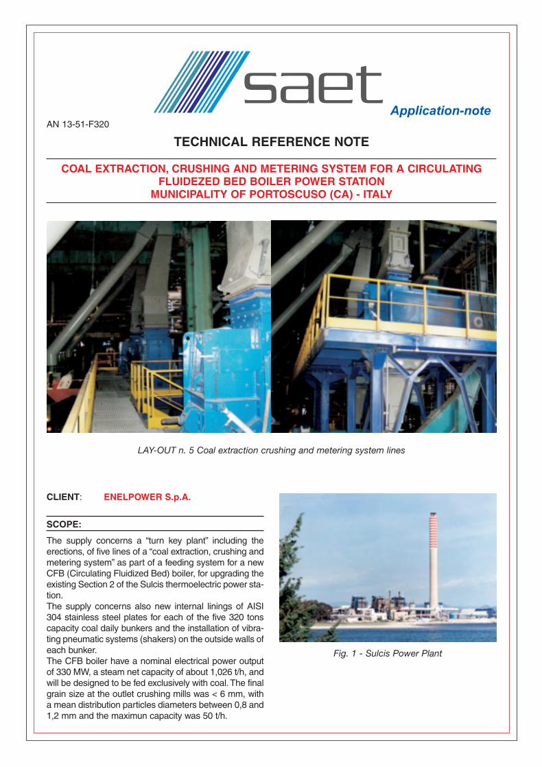
Fig. 1 - Sulcis Power Plant
AN 13-51-F320 9-09-2004 14:03 Pagina 1
SUPPLY COMPOSITION
ENGINEERING• Base and detailed (civil, mechanical, electrical,
instrumentation)MECHANIC• N°5 slide gate valve• N°5 conveyors feeder dust tight faired• N°5 reversible coal hammer mill• N°5 support steel structure for hammer mill• Ducts, hoppers for coal conveying system• N°5 expansion joints• N°5 new internal Stainless Steel AISI 304 lining ofdaily coal bunkers• Vibrating pneumatic system consisting in n°2
shakers for each bunkerELECTRIC - INSTRUMENTATION• N°1 Power Motor Control Center• N°1MV/LV distribution Transformer• N°5 Inverters for conveyors feeder motors
DESCRIPTION
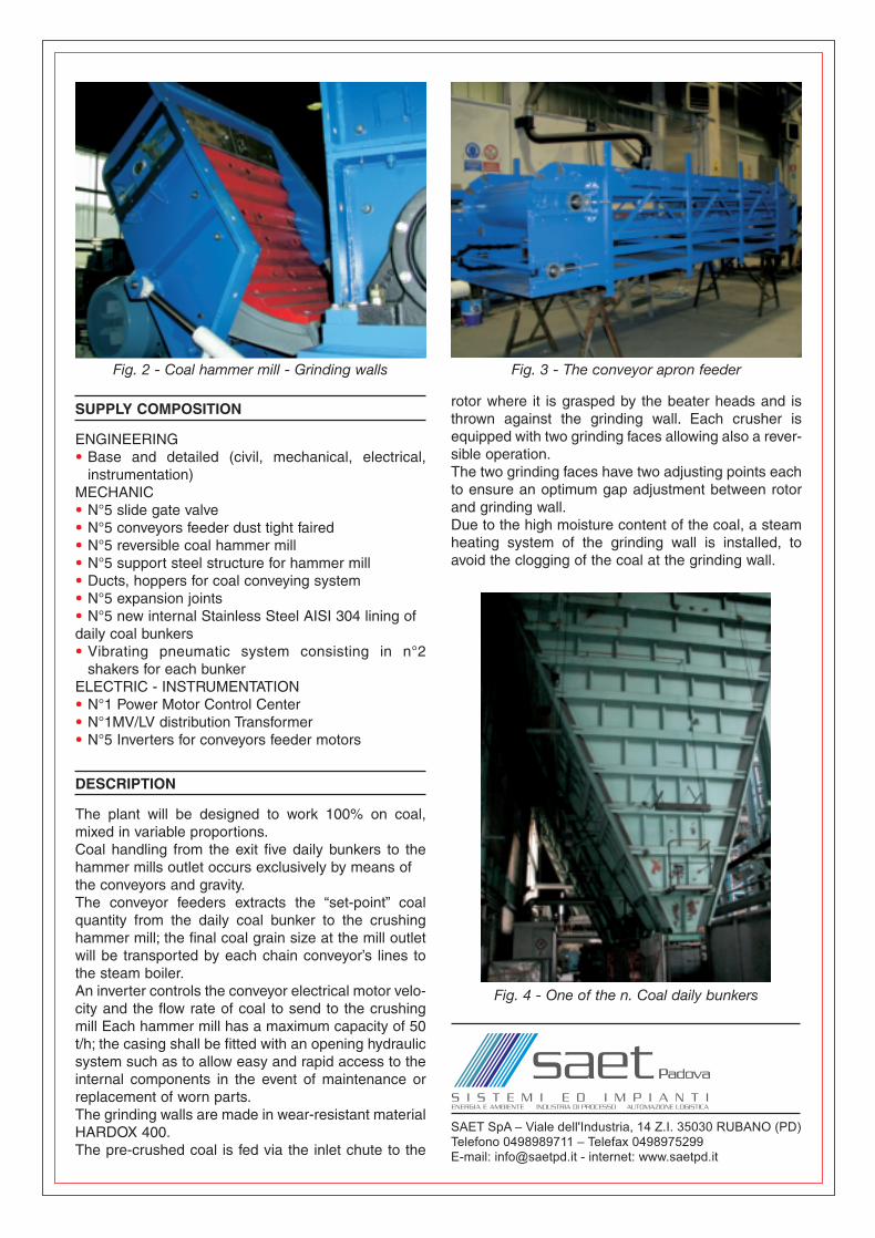
The plant will be designed to work 100% on coal,mixed in variable proportions.Coal handling from the exit five daily bunkers to thehammer mills outlet occurs exclusively by means ofthe conveyors and gravity.The conveyor feeders extracts the “set-point” coalquantity from the daily coal bunker to the crushinghammer mill; the final coal grain size at the mill outletwill be transported by each chain conveyor’s lines tothe steam boiler.An inverter controls the conveyor electrical motor velo-city and the flow rate of coal to send to the crushingmill Each hammer mill has a maximum capacity of 50t/h; the casing shall be fitted with an opening hydraulicsystem such as to allow easy and rapid access to theinternal components in the event of maintenance orreplacement of worn parts.The grinding walls are made in wear-resistant materialHARDOX 400.The pre-crushed coal is fed via the inlet chute to the
rotor where it is grasped by the beater heads and isthrown against the grinding wall. Each crusher isequipped with two grinding faces allowing also a rever-sible operation.The two grinding faces have two adjusting points eachto ensure an optimum gap adjustment between rotorand grinding wall.Due to the high moisture content of the coal, a steamheating system of the grinding wall is installed, toavoid the clogging of the coal at the grinding wall.
Fig. 2 - Coal hammer mill - Grinding walls Fig. 3 - The conveyor apron feeder
Fig. 4 - One of the n. Coal daily bunkers
AN 13-51-F320 9-09-2004 14:03 Pagina 2