Embed Size (px)
Citation preview

AN L-85-38
tt)
ANL-85-380((U7
EXPERIMENTAL STUDY ON IMPACT/FRETTING WEAR
IN HEAT EXCHANGER TUBES
by
J. H. Cha, M. W. Wambsganss,and J. A. Jendrzejczyk
tx ONAL
i. 40
o T
OF
ARGONNE NATIONAL LABORATORY, ARGONNE, ILLINOIS
Operated by THE UNIVERSITY OF CHICAGOfor the U. S. DEPARTMENT OF ENERGY DISTRBuIo N oTHIS DOCUMENT IS ImtINunder Contract W-31.109-Eng-38
/.j/3 lob
/ s
A major purpose of the Techni-cal Information Center is to providethe broadest dissemination possi-ble of information contained inDOE's Research and DevelopmentReports to business, industry, theacademic community, and federal,state and local governments.
Although a small portion of thisreport , is not reproducible, it isbeing made available to expeditethe availability of information on theresearch discussed herein.
ANL--85-38
DE85 014597
ARGONNE NATIONAL LABORATORY9700 South Cass Avenue
Argonne, Illinois 60439
EXPERIMENTAL STUDY ON IMPACT/FRETTING WEAR INHEAT EXCHANGER TUBES
by
J. H. Cha, M. W. Wambsganss, and J. A. Jendrzejczyk
Components Technology Division
April 1985
*
Visiting Scientist, Korea Advanced Energy Research Institute
DISTRIBUTION of THIS DgCUMENI IS I IUL11E

3
CONTENTS
Page
ABSTRACT............................. ...................................... 7
1. INTRODUCTION.................................................... 8
II. TEST DESCRIPTION ................................................ 9
A. Test Hardware....................................................... 9
B. Test Procedure................................. ..... . 19
C. Test Parameters and Conditions.............................. 21
III. TEST RESULTS................... ................. . 22
A. Tube Motion ................................................. 22
B. Impact Force......................... 24
C. Clearance between Tube and Tube Support Plate.................24
D. Tube Support Plate Thickness ................................ 30
E. Excitation Frequency........................................ 30
F. Duration of Test........................................ 36
G. Material Combination........................................ 36
H. Liquid Environment.......................................... 42
IV. DISCUSSION ...................................................... 42
V. CONCLUSIONS ..................................................... 50
ACKNOWLEDGMENTS ....................................................... 52
REFERENCES..................... ....................................... 53

4
FIGURES
Page
1 General Photographic View of Test Apparatus ... . .. . 10
2 Photograph of Tube, Excitation Coils and Test Section.......... 12
3 Schematic of Test Fixture...................................... 13
4 Close-up Photograph of Wear Test Section....................... 14
5 Photographic View of Force Transducer Mounting Block........... 15
6 Sectional View of Force Transducer Mounting Block.............. 16
7 General Diagram of Test Apparatus.............................. 17
8 Photograpoic View of In-Water Test............................ 18
9 Photograph of Specimen Samples..................................20
10 Examples of Tube Vibration atterns.............................23
11 Sample of Force and Displacement Records without Preload....... 25
12 Sample of Force and Displacement Records with Preload.......... 26
13 Impact Force vs. Excitation Force at Tube Support Plate........ 27
14 Wear Rate vs. Impact Force, Frequency: 26 Hz, Tube/TSPClearance (diametral): 0.78 mm, TSP Thickness: 14.27 mm,Preload: None........... ....................................... 28
15 Wear Rate vs. Tube/TSP Clearance, Excitation Force: 6.14 N,
Frequency: 26 Hz, TSP Thickness: 14.27 mm, Preload: 5.56 N..... 29
16 Impact Force vs. Tube/TSP Clearance without Preload, Frequency:26 Hz, TSP Thickness: 14.27 mm................................. 31
17 Impact Force vs. Tube/TSP Clearance with Preload, Frequency:
26 Hz, TSP Thickness: 14.27 mm................................. 32
18 Wear Rate vs. TSP Thickness, Excitation Force: 6.14 N,Frequency: 26 Hz, Tube/TSP Clearance (diametral): 0.78 mm,
19 Wear Rate Variation with Frequency. Impact Force: 39 N, Tube/TSP Clearance (diametral): 0.78 mm, Material: Carbon Steel,
Preload: 5.56 ................................................ 34
20 Comparison of Displacement Records with Time of 26 Hz and
60 Hz. ..............-- ........................................ 35
5
21 Wear Rate as a Function of Test Duration, Excitation Force:6.14 N, Frequency: 26 Hz, Tube/TSP Clearance (diametral):0.78 mm, TSP Thickness: 14.27 mm, Preload: None................ 37
22 Wear Rate as a Function of Test Duration, Excitation Force:6.14 N, Frequency, 26 Hz, Tube/TSP Clearance (diametral):0.78 mm, TSP Thickness: 14.27, Preload: 5.56 N................. 38
23 Wear Rate with Test Duration for Carbon Steel/304 StainlessSteel Combination, Excitation Force: 6.14 N, Frequency: 26 Hz,Tube/TSP Clearance (diametral): 0.78 mm, TSP Thickness:14.27 mm, Preload: 5.56 N..................................... 39
24 Wear Rate with Test Duration for Carbon Steel/Inconel 600Combination, Excitation Force: 6.14 N, Frequency: 26 Hz,Tube/TSP Clearance (&:iametral): 0.78 mm, TSP Thickness:14.27 mm, Preload: None...................................o.... 40
25 Wear Rate with Test Duration for Carbon Steel/BrassCombination, Excitation Force: 6.14 N, Frequency: 26 Hz,Tube/TSP Clearance (diametral): 0.78 mm, TSP Thickness:14.27 mm, Preload: 5.56 N. ..................................... 41
26 Comparison of Wear Rates of In-Air and In-Water Tests,Excitation Force: 6.14 N, Frequency: 26 Hz, Tube/TSP Clearance(diametral): 0.78 mm, TSP Thickness: 14.27 mm, Material:Carbon Steel, Preload: None.................................... 43
27 Comparison of Wear Rates of In-Air and In-Water Tests,Excitation Force: 6.14 N, Frequency: 26 Hz, Tube/TSP Clearance(diametral): 0.78 mm, TSP Thickness: 14.27 mm, Material:Carbon Steel, Preload: 5.56 N.................................. 44
28 Appearance of a Worn TubeSpecimen............................. 46
29 Microphotograph of a Worn Surface of 304 Stainless Steel TubeSpecimen (x 1000) .............................................. 48
30 Microphotograph of a Worn Surface of Inconel 600 TubeSpecimen (x 1000) .............................................. 49
31 Comparison of Experimental Data and Empirical Curvef it ofEq. (1) for Carbon Steel/Carbon Steel Combination in Air....... 51

6
TABLES
Page
1 Material Specificationst..................................... 19
2 Selected Parameters and Test Condit ons ........................ 21
7
EXPERIMENTAL STUDY ON IMPACT/FRETTING WEAR INHEAT EXCHANGER TUBES
by
J. H. Cha, M. W. Wambsganss, and J. A. Jendrzejczyk
ABSTRACT
A data bank of field experiences with heat exchanger tube
vibration reveals numerous cases of tube failures at, or near,the baffle. The failures can be attributed to impact and/or
fretting wear due to flow-induced vibrations. In spite of the
occurrence of serious wear problems in heat exchangers, only a
few investigations have been reported. The objective of this
study is to provide qualitative impact/fretting wear information
for heat exchanger tubes through the performance of a series of
tests involving the pertinent parameters: impact force level,
between the tube and its support; tube to support plate hole
clearance; tube support plate thickness; and tube vibration
frequency. The characteristics of impact/fretting wear relative
to tube motion pattern, material combination and surroundingfluid were also investigated. The test apparatus consists of a
cantilevered tube with a simulated tube support plate at the"free end". Tube vibration is induced by an electromagnetic
exciter to simulate the flow-induced tube motion occurring in a
real heat exchanger at the tube/tube support plate interface.
Tests are conducted in air, water, and oil, all at room
temperature. Removable wear rings are attached to the tube free
end and simulated support fixture. Wear ring materials include
carbon steel, 304 stainless steel, Inconel 600 and brass. The
resulting impact/fretting wear is measured by the weight loss
technique. The principal results of the tests are as follows:
Wear rate increases significantly with the magnitude of the
impact force between the tube and its support plate; the degree
and trend of the wear rates are highly dependent on the
mechanical and metallurgical properties of the tube/support
material combination; the rate of impact/fretting wear decreaseswith increasing frequency. The results also show that the wear
rate for carbon steel in water is greater in comparison with thevalues from the in-air tests. On the other hand, the wear rate
from tests in oil is very much lower than the results from the
tests in both air and water. An empirical formula is proposed
to correlate the experimental impact/fretting wear results.

8
I. INTRODUCTION
Because of the small clearance existing between a heat exchanger tubeand the tube support plate hole, flow-induced vibration of the heat
exchanger tube bundle can cause relative motion at the tube/supportinterfaces which, in turn, can result in impact/fretting wear. Severe
impact/fretting wear will eventually lead to heat exchanger tube failures asdocumented in a series of heat exchanger tube vibration data bank reports
published by Argonne National Laboratory [1]. The case histories of fieldexperiences include numerous examples of tube cutting failures at, or near,
the baffles which can be attributed to impact/fretting wear due to flow-
induced vibration.
There is a large volume of literature on the subject of wear thatincludes presentations of wear data, discussions of wear testing techniques,
and the development of mathematical models for wear. However, in spite ofthe seriousness of impact/fretting wear problems in heat exchangers, there
is only limited information reported in the open literature on tube/support
wear in heat exchangers, or steam generators.
Numerous data were obtained in the early stages of the investigation of
the fretting wear mechanism as an aspect of tribological science. For
example, Feng and Uhlig [2] observed and reported several charateristics of
fretting wear with mild steel. These included the following: Metal loss
increases with load and relative slip; greater damage occurs at temperaturesbelow room temperature; damage is greater in dry air than in moist air:
fretting wear is reduced in a vacuum or an inert atmosphere.
Significant investigations which have contributed to the understanding
of tube/support wear in heat exchangers have been made by Ko [3] and Blevins
[4].
In Ko's tube wear tests, a single span cantilevered tube, with tube andtube support plate specimens located at the free end, is used. A specially
designed vibration generator allows for controlled umI.uirectional, orcombined impact and sliding, motions. Fretting wear rate is measured for
various material combinations and geometries. Ko's major results show thatthe fretting wear rate increases with tube support reaction forces and
tube/support clearances; and that the wear rate is higher under combined
impact and rubbing motions compared with impact motion alone.
Blevins made measurements of fretting wear using a test rig in which a
tube, attached at its midpoint to a shaker, is vibrated such that impacting
and rubbing can occur between the tube and simulated support plates located
at each of the free ends. Blevins measured wear as a function of suchparameters as midspan vibration amplitude, vibration frequency, preload
against support, tube/support clearance, support plate thickness, tube wall
thickness, and tube and support plate materials. Some interesting results
of his tests are as follow: T1h' wear rate of the tube and support plate are
approximately equal if both the tube and the support plate are made of the
same material; the wear rate is a function of the material and its hardness;
9
the fretting wear rate increases with both the frequency and amplitude oftube vibrations; the wear rate decreases sharply with increasing preload
applied to the tube at the tube/support interface. Blevins has alsopresented an investigation [5] on the development of a vibration-induced
wear model based on impact theory and the measurement of wear rates in
helium at high temperature, up to 650*C.
In order to analyze the impact/fretting wear process, fundamental
studies of tube/support interaction forces and motions have been performed
and reported by Chen et al. [6], Shin et al. [7], and Rogers and Pick
[8,9]. In references 6 and 7, only normal impacting is considered, whereas
in references 8 and 9 two-dimensional, spatial motion is simulated. The
results of the analytical simulations, when compared with experimental
results from a single-span cantilevered tube [9] and a clamped-clamped tube
with stop at midspan [7], have been shown to predict the basic trends andfeatures of the interaction forces and motions as well as the amplitudes
within 50 percent of the measured values. Axisa et al. [10] recentlyinvestigated the relationship between impact forces and non-linear tube
motion based on an experimental study of the vibro-impact response of a
straight segment of a U-bend steam generator tube with tube-baffle
interaction at the support. Frick et al. [11] attempted to develop a
procedure to produce vibration and wear time history information for steam
generator and heat exchanger tubes using a single tube, 3-D, non-linear
dynamic model.
Previous investigators have made significant contributions revealingthe characteristics of fretting wear. Nevertheless, it is not yet clearly
understood and much remains to be done. The objective of this study is to
generate qualitative impact/fretting wear data that will provide additional
insights to this complex phenomenon that is so important in the design
evaluation of heat exchangers. A series of tests are performed involvingthe essential parameters: Magnitude of impact force between tube and its
suport; tube to support clearance; tube support plate thickness; and
excitation frequency. Time-histories of tube impact/fretting wear forseveral material combinations and the effect of surrounding fluid are also
studied.
II. TEST DESCRIPTIONA. Test Hardware
The test apparatus consists of a cantilevered tube with a tube specimen
(wear ring) attached to the free end, a tube support plate (TSP) specimen
(wear ring) clamped in a steel and brass base block which is located at the
1 vel of the free end of the tube, an electromagnetic exciter assembly, a
transducer assembly, the test apparatus frame, and related electronic
equipment. A general view of the test aparatus is shown in Fig. 1.
The tube, 16 mm OD x 1.2 mm thickness x 953 mm long and fabricated of
seamless Croloy (2-1/4% Cr - 1% Mo), is vertically mounted and securely

1119196195655
jFig. 1. General Photographic View of Test Apparatus (ANL Neg.
C-
Knox,,4
I
No. 113-85-16)

11
clamped at its upper end to the frame. The tube is excited by an
electromagnetic exiter assembly consisting of eight pairs of drive coils
(300 turns of No. 12 Farmver wire for zach coil) mounted to the frame and
positioned along the length of the tube. The exciter assembly is connected
to a sine-wave generator and power amplifier. The frequency of tube
vibration is controlled by varying the sine-wave generator, and the
excitation force level is controlled by the power amplifier. The tube and
tube support plate specimens are in the form of annular wear rings. The
excitation coils provide tube motion in the horizontal direction. The tube
specimen is vibrated against a tube support plate specimen ared
impact/fretting wear is produced between the two test specimens. A
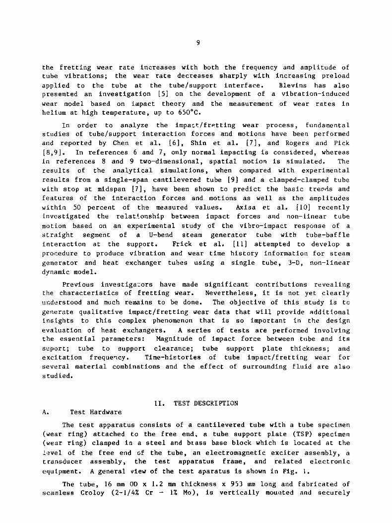
photograph of the cantilevered tube, excitation coils, and test section is
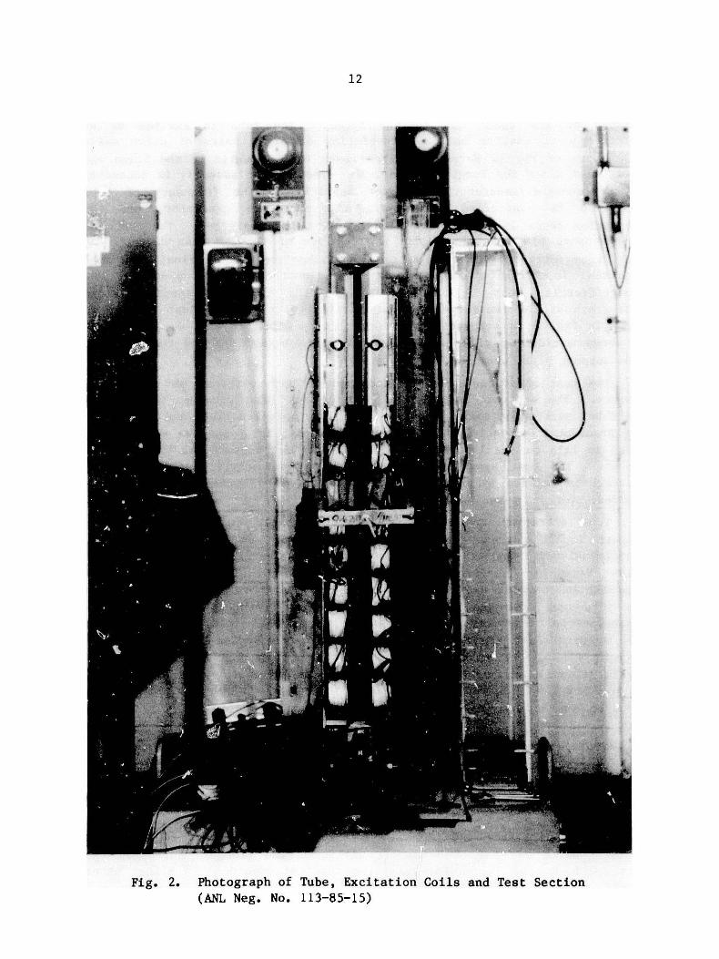
shown in Fig. 2; a schematic representation is given in Fig. 3. In Fig. 4
is shown a close-up view of the support plate base block and the tube and
tube support plate wear specimens.
The test apparatus frame is composed of both vertical and horizontal
members. The vertical member is a "strong-back" that provides support for
the tube, excitation coils, tube support plate specimen block and clamp, and
the transducer assembly. The horizontal member is a massive steel block
which is laid on the laboratory floor and provides support for the vertical
member. The test apparatus is made sufficiently rigid that significant
interaction between tube and test fixture caused by mechanical coupling is
avoided.
Tube vibration response, including frequency, amplitude, and tube/
support impact force is measured by displacement and force transducers.
Two-dimensional transverse displacement of the tube is sensed by a pair of
Kaman Variable Impedance Transducers (Model KD-2300-6C) orthogonally
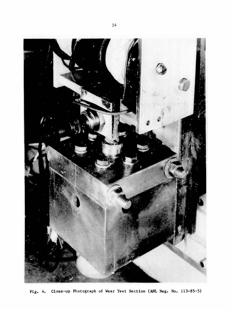
oriented and mounted near the free end of the tube. Impact force between
the tube and tube support plate specimens is measured with a triaxial
piezoelectric force transducer (Kistler Model 9067) inserted between the
tube support plate specimen block and transducer mounting block as seen in
Figs. 5 and 6. A separate force transducer block was fabricated to be
similar in function and geometry to that of the main wear test block. The
force transducer block was installed by replacement of the main block
whenever impact force measurements were desired.
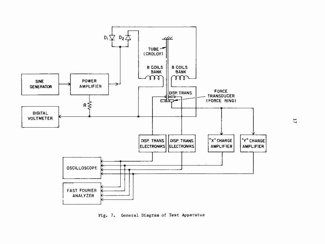
An oscilloscope was used to visually observe the tube motions sensed by
the displacement transducers. The displacements and forces were analyzed
with a Fast Fourier Analyzer (Model H.P. 5451C), and force time histories,power density spectra, and force histograms were produced. A schematic of
the instrumentation and associated electronics is shown in the diagram of
Fig. 7.
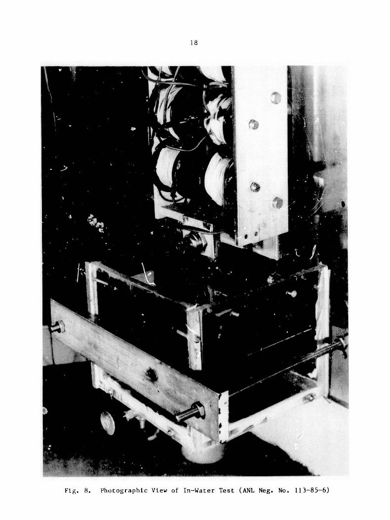
For the in-water and in-oil tests, a acrylic plastic (200 x 200 x
150 mm), which was sealed by rubber strips at the flanges, surrounds the
test specimens and allows for immersing the test specimens in either water
or oil, as shown in Fig. 8.
12
I J
{
(ANL Neg. No. 113-85-15)
{
w.

13
BRASS BLOCK
CROLOY TUBE
SPRING FOR PRELOAD
STEEL SUPPORT PLATE
SPRING SUPPORT
EXCITATION COILS
TUBE SPECIMEN
TSP SPECIMEN
SPECIMEN CLAMP BLOCK
Fig. 3. Schematic of Test Fixture
14
* ~is.
7%
yk c I
Fig. 4. Close-up Photograph of Wear Test Section (ANL Neg.
tfv,,_ ,.* aa_.
No. 113-85-5)

15
t*
-."". "" ' o ...r}t.h4 . .
4N
Fig. 5. Photographic View of Force Transducer Mounting Block(ANL Neg. No. 113-85-8)
d" e 4 S ., _- ~
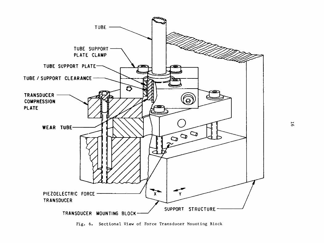
TUBE
TUBE SUPPORT
PLATE CLAMP
TUBE SUPPORT PLATE
TUBE / SUPPORT CLEARANCE
TRANSDUCERCOMPRESSIONPLATE
WEAR TUBE
PIEZOELECTRIC FORCETRANSDUCER
SUPPORT STRUCTURETRANSDUCER MOUNTING BLOCK
Fig. 6. Sectional View of Force Transducer Mounting Block
D, D2
TUBE(CROLOY)
8 COILS 8BANK
DIS
-IL
FORCETRANSDUCER(FORCE RING)
-* 4.0
DISP TRANS. DISP TRANS.ELECTRONIKS ELECTRONIKS
"X" CHARGE "v' CHARGEAMPLIFIER AMPLIFIER
OSCILLOSCOPE
FAST FOURIERANALYZER
_________________________________________I
a I
Fig. 7. General Diagram of Test Apparatus
COILSBANK
5P. TRANS.
Th-VOLTMETER H-
I
-"- &-A
SINE POWER
GENERATOR AMPLIFIER
R
DIGITAL
18
S'M
Fig. 8. Photographic View of In-Water Test (ANL Neg. No. 113-85-6)
19
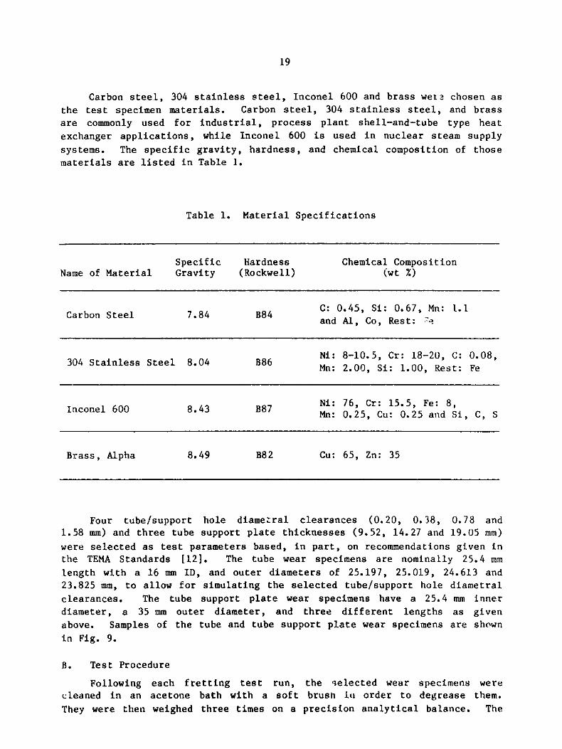
Carbon steel, 304 stainless steel, Inconel 600 and brass were chosen as
the test specimen materials. Carbon steel, 304 stainless steel, and brass
are commonly used for industrial, process plant shell-and-tube type heat
exchanger applications, while Inconel 600 is used in nuclear steam supply
systems. The specific gravity, hardness, and chemical composition of those
materials are listed in Table 1.
Table 1. Material Specifications
Specific Hardness Chemical CompositionName of Material Gravity (Rockwell) (wt %)
C: 0.45, Si: 0.67, Mn: 1.1Carbon Steel 7.84 B84 and Al, Co, Rest: 7
Ni: 8-10.5, Cr: 18-20, C: 0.08,304 Stainless Steel 8.04 B86 Mn: 2.00, Si: 1.00, Rest: Fe
Inconel 600 8.43 B87 Ni: 76, Cr: 15.5, Fe: 8,Mn: 0.25, Cu: 0.25 and Si, C, S
Brass, Alpha 8.49 B82 Cu: 65, Zn: 35
Four tube/support hole diametral clearances (0.20, 0.38, 0.78 and1.58 mm) and three tube support plate thicknesses (9.52, 14.27 and 19.05 mm)
were selected as test parameters based, in part, on recommendations given inthe TEMA Standards [12]. The tube wear specimens are nominally 25.4 mm
length with a 16 mm ID, and outer diameters of 25.197, 25.019, 24.613 and23.825 mm, to allow for simulating the selected tube/support hole diametral
clearances. The tube support plate wear specimens have a 25.4 mm inner
diameter, a 35 mm outer diameter, and three different lengths as given
above. Samples of the tube and tube support plate wear specimens are shown
in Fig. 9.
B. Test Procedure
Following each fretting test run, the selected wear specimens werecleaned in an acetone bath with a soft brush in order to degrease them.
They were then weighed three times on a precision analytical balance. The

Photograph of Specimen Samples (ANL Neg. No. 113-85-13)
0
Fig. 9.
y

21
specimens were then installed in the test rig and vibration initiated at the
desired excitation force level and frequency. Preload, if any, was applied
to the midspan of the tube by spring tension as illustrated in Fig. 3.
Testing was terminated after continuous running for a giv.27 number of
cycles. The wear specimens were recleaned, in order to rinse off any loose
debris, and reweighed. The weight loss of the specimens was calculated and
normalized by dividing by the total number of cycles of vibration during the
test run.
Upon completion of the in-air series of tests, the tank was attached
and filled with room temperature water, and a similar set of tests was
performed. Following the in-water tests, the water was replaced by oil and
a set of in-oil tests was carried out. The oil temperature was controlled
by an immersion type heater equipped with a thermostat. The necessary
signals from the transducers were tape recorded for further data processing.
C. Test Parameters and Conditions
Impact/fretting wear of heat exchanger tubes depends on the tube andsupport geometries, relative motion at the tube/support interface, the type
and magnitude of tube/support reaction forces, material combinations, and
environmental conditions. The following table lists the selected parameters
and test conditions for this experimental study.
Table 2. Selected Parameters and Test Conditions
T/TSP TSP Excitation ExcitationClearance Thickness Force Frequency Material
(diametral, mm) (mm) (N) (Hz) Combination Fluid
0.20 9.52 0.13 10 CS:CS Air
0.38 14.27 0.28 26 SS:SS Water
0.78 19.05 0.54 40 In:In Oil
1.58 0.93 60 Br:Br
1.38 80 SS:CS
1.87 In:CS
Br:CS
where CS: carbon steel, SS: 304 stainless steel, In: Inconel 600, Br: Brass

22
In some tests a preload of 5.56 N was applied. The in-air and in-water
tests were conducted at room temperature, the in-oil tests were performed at
a temperature of 450C. Most of the tests were run for 24 hours. However,
some tests were run for 120 hours to observe the variation of wear rate with
time.
III. TEST RESULTS
Experimental parameters known to influence impact/fretting wear of heat
exchanger tubes are generally contact conditions between the tube and its
support, material properties and response behavior, and environmental
conditions. The focus of this work is on those parameters for which results
pertaining to impact/fretting wear are tube motion, impact force, clearance
between tube and support plate hole, tube support plate thickness, frequency
of vibration, test duration, material combination, and fluid environment.
A. Tube Motion
The flow-induced vibration mechanisms that can cause impact/frettingwear of heat exchanger tubes are fluidelastic excitation, turbulence
buffeting, and vortex shedding. Fluidelastic excitation is believed to be
the cause of large amplitude vibration and, therefore, rapid wear of heat
exchanger tubes. Wambsganss et al. [13] observed that, for the industrial
size shell-and-tube exchanger used in their tests, the primary contribution
to the vibration response was in the frequency range from 10 to 80 Hz; it
was also observed that tube response associated with fluidelastic insta-
bility typically occurred in the frequency range of 20 to 30 Hz. Based, in
part, on these findings, the majority of the subject tests were performed at
the low frequency of 26 Hz.
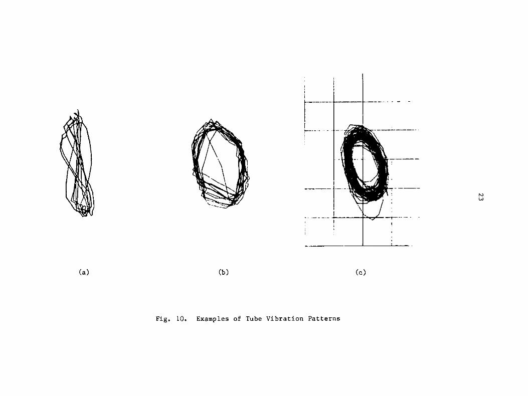
Heat exchanger tubes are usually excited into different vibrationpatterns: random, straight line in lift or drag direction, and whirling,
depending, in part, on the flow range. A representative tube vibrationpattern from tests of an actual heat exchanger is presented in Fig. 10(a)
[14]. In the subject tests, the tube motions are determined by the
excitation forces and the preload. Figures 10(b) and (c) are examples of
typical tube vibration patterns that were employed. Figure 10(b) gives a
vibration pattern corresponding to a low excitation force level (0.28 N) and
Fig. 10(c) shows an example for a high excitation force level (1.38 N). The
tests show that the ratio of the two orthogonal impact force components,
F /F , is in the range of 1.76 at lower excitation force and 4.50 at higher
excitation force without preload, and 1.64 at lower excitation force and
1.92 at higher excitation force with preload. The ratio Fx/Fy approximately
equal to a or 0 implies that the tube motion is primarily one of straight
line motion, giving rise to impacting. With F /Fy approaching 1 the tube
has the tendency to whirl.
)
(b)
Fig. 10. Examples of Tube Vibration Patterns
(a)
i
Lii
(c)
___
1
1
r i
"
.. ---
4 "

24
B. Impact Force
During the tests, impact forces at the tube support plate were measuredwith a force transducer, together with the measurement of displacement
variations. Figures 11 and 12 show sample time-histories of the variation
of impact forces and displacements at the support location: It can be seenthat F and D components in the preload case are somewhat larger than those
y yfor the case of no preload. The maximum values of two mutually perpendicu-lar forces are used to represent the resultant impact force at the
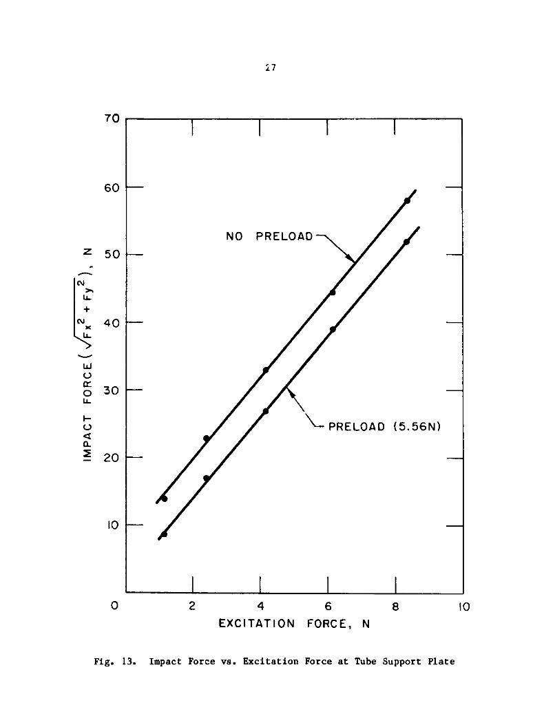
support. Figure 13 shows the relationship between the resultant impact
force at the support and the excitation force generated by the excitation
coils. The relationship is nearly linear.
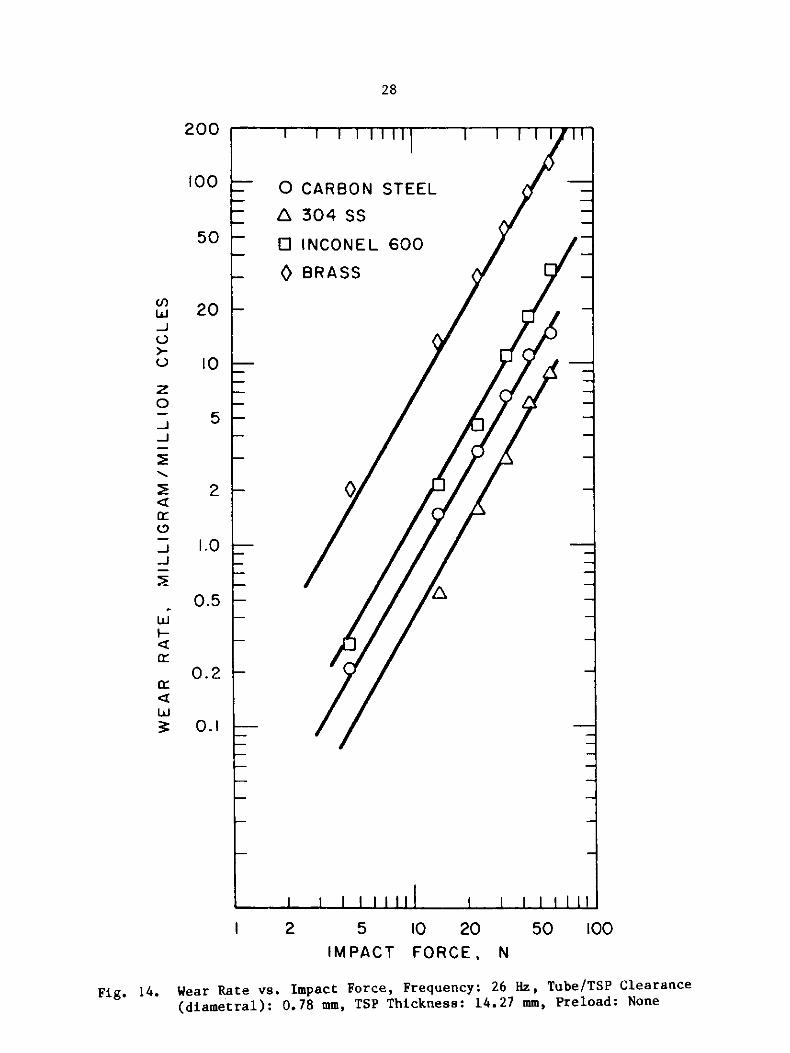
Figure 14 illustrates the influence of impact force on theimpact/fretting wear rate of tubes for the case of a constant frequency
excitation and tube/tube support plate in air. Each test point was taken
after 24 hours running. The results show that the wear rate, for each of
the four material combinations, is rapidly increasing with increasing impact
force level. It was learned from the results that the impact force at the
support is the primary parameter determining wear. The wear rate as afunction of impact force for the four materials can be expressed as:
w = k1F l, where w is wear rate (mg/106 cycles), F is resultant impact force(N), and k1 and a1 are constants. Using least squares curve fitting
techniques, the following constants were obtained: exponent a1 is 1.72 for
all four materials; and constant k1 is 0.0068 for 304 stainless steel, 0.014
for carbon steel, 0.024 for Inconel 600, and 0.12 for brass. The wear rateof 304 stainless steel is the lowest, while brass has the highest wear
rate. There is no evidence of material hardness effect on wear when both
the tube and the tube support plate are the same material.
In order to control the tube motion pattern, preload was applied on thetube, at a point 43.5 cm from the top of the tube, by means of the tension
force of spring. It should be noted that while preload acts to increase the
static force, it reduces the impact force and, in this case, results in
reduced wear.
C. Clearance between Tube and Tube Support Plate
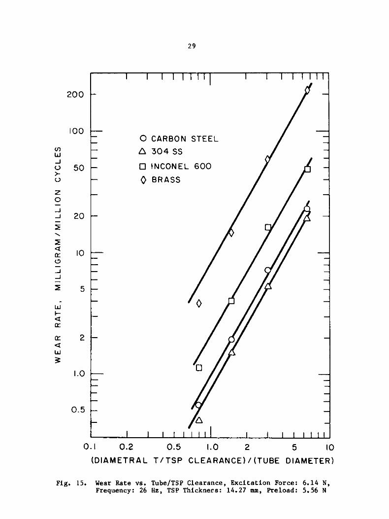
Data presented in Fig. 15 shows the effect of an increase in diametral
clearance between the tube and tube support plate hole on the wear rate in
air for the four materials with fixed excitation force level, excitation
frequency, and tube support plate thickness. In the tests, four clearances
were examined by varying the outer diameter of the tube specimen; both the
tube and tube support plate are made of the same material. The clearance in
Fig. 15 refers to the clearances at the start of the tests. By the end of a24-hour test, these clearances had increased slightly. Figure 15 indicates
the rapid increase in wear rate with increasing clearance between tube and
support plate hole that many investigators have observed. The results allow
one to conclude that the smaller the clearance between tube and tube support
plate hole, the smaller will be the wear rate. The trend of increasing wear

25
I I I I Ir
0 0.1 0.2
TIME, SEC.NO PRELOAD
Fig. 11. Sample of Force and Displacement Records without Preload

26
0.I
TIME, sec
Fig. 12. Sample of Force and Displacement Records with Preload
Fx
Fy
Dx
Dy
0 0.2
l I I V41W I
_-
.7
/NO PRELOAD
PRELOAD (5.5 6N)
4
EXCITATION
6FORCE, N
Fig. 13. Impact Force vs. Excitation Force at Tube Support Plate
70
60 F--
50 --
40 -
z
LL
+
0
-
30-
20-
10
0 2 8 I0
I I N I
1 1 I
II I I
I I I I
28
200
100
50
I I I I11I il I I I I Ilt
5 10 20 50 100IMPACT FORCE, N
Fig. 14. Wear Rate vs. Impact Force, Frequency: 26 Hz, Tube/TSP Clearance
(diametral): 0.78 mm, TSP Thickness: 14.27 mm, Preload: None
1
- o
- A
1 1 I 11111 1 I I I II
CARBON STEEL
304 SS
INCONEL 600
BRASS
A-
(Ir)LU.J0
0
z0
O-
-J
a:
-J
-
wrHW:
20
t0
5
2
1.0
0.5
0.2 I-
o.1
I 2
- v-- --- w vv v v -
1 1 1 1 1 1 1 1 1
29
I I I I I I III I I I I I I
o CARBo04
A 304 SS
STEEL
-JV
z0
-J
0
-J-J
Wi
Hc
a:a:
0.2 0.5 1.0 2 5 10
(DIAMETRAL T/TSP CLEARANCE) / (TUBE DIAMETER)
Fig. 15. Wear Rate vs. Tube/TSP Clearance, Excitation Force: 6.14 N,Frequency: 26 Hz, TSP Thickness: 14.27 mm, Preload: 5.56 N
200
100
50
20
10
5
o INCONEL 600
- BRASS
0 -
-- A
2
1.0
0.5
0.I
NV

30
rate with increasing clearance between tube and support plate hole can be
expressed as an exponential relationship, w = k2(Cd/D)2, as seen inFig. 15, where Cd is diametral clearance at the support plate, and D is tube
outer diameter. It was found that the exponent a2 is approximately 1.76 for
all four materials and that the constant k2 is 0.75 for 304 stainless steel,
0.97 for carbon steel, 2.06 for Inconel 600, and 8.3 for brass.
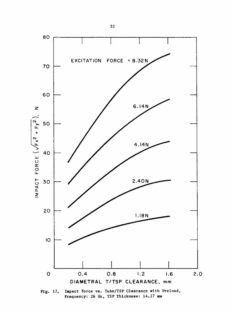
Force measurements, made with these clearances, show that the support
reaction force increases with increasing clearance while the excitation
force and frequency are kept constant; see Figs. 16 and 17. These results
indicate that increasing the clearance between tube and support plate hole
results in larger reaction forces at the support. It follows then that
increasing the clearance, increases the wear rate.
D. Tube Support Plate Thickness
To investigate the effect of tube support plate thickness, tests were
performed using tube support plate specimens of three different
thicknesses. The tests were performed in air for four material combinations
with fixed excitation force level, excitation frequency, and tube-to-support
hole clearance. Figure 18 shows a decreasing wear rate, expressed in terms
of loss of tube depth, with increasing thickness of the tube support plate;
this agrees with the findings of other investigators [3,4].
During the tests, the impact forces at the support were measured for
each tube support plate thickness, however, no consistent force differences
could be found. It appears that this finding can be attributed to the
effect of higher local stress generation at the smaller thickness tube
support plate.
E. Excitation Frequency
Figure 19 shows the variation of wear rate, measured on the tube
specimen, as a function of excitation frequency for carbon steel with a
constant impact force at the support. In the low frequency region (< 40 Hz)
there is no evidence of a significant frequency effect on wear rate, as also
reported by Ko [3]. In the higher frequency region (> 40 Hz), however, wear
rates decrease considerably with increasing frequency. In the frequency
range of these experiments, it appears that the wear rate of tube varies
hyperbolically with frequency.
The decrease in the fretting wear rate in the higher frequency region
can probably be attributed to the decrease in contact time between the two
bodies during impacting, as can be seen in Fig. 20. In these tests, it was
found that the contact times were about 0.022 sec per cycle for 26 Hz, and
about 0.010 sec per cycle for 40 Hz; for further comparison, the contact
time was about 0.005 sec per cycle for 60 Hz. Accordingly, at higher
frequencies where the contact time per cycle of excitation is short, the
overall weight loss is less.

31
70
EXCITATION FORCE = 8.32N
6.14N ob
4.14N
2 .4 0O N lillillllllllllm
1.18N
60 F-
50 F-
40 F-
30 F--
20 I-
10 -
0 0.4 0.8 1.2 1.6DIAMETRAL T/TSP CLEARANCE, mm
Fig. 16. Impact Force vs. Tube/TSP Clearance without Preload,Frequency: 26 Hz, TSP Thickness: 14.27 mm
z
+
LL
LU
0LL.
a--2
2.0
--
-- 1 - - 1
I I II
I I I I
32
80
70
0.8 1.2 1.60.4 2.0
DIAMETRAL T/TSP CLEARANCE, mm
Fig. 17. Impact Force vs. Tube/TSP Clearance with Preload,Frequency: 26 Hz, TSP Thickness: 14.27 mm
EXCITATION FORCE = 8.32N
6.14N
4 .14 N
2.40N
1.18 N
60 k-
z
5 0 -
40 ---
N
N
LL
LWV
0LL-
()
02
20k-
10 I-
0
1 l 1 1
I I I I
3 0 j-
I I I

33
8
7
6
5
-J 4
o 3 CARBON STEEL
A 304SS
Z 0 INCONEL 600
0 BRASS-'2.0
E 1.8
1.6I-
S1.4
w 1.2
\.0
0.8
0.6
0.4
0.2
0
0.6 1.0 1.4 1.8 2.2TSP THICKNESS, cm
Fig. 18. Wear Rate vs. TSP Thickness, Excitation Force: 6.14 N, Frequency:26 Hz, Tube/TSP Clearance (diametral): 0.78 mm, Preload: 5.56 N

34
10
.J
08
z
.J
O O
-J
-4
OO
a: c 2 -
0 20 40 60 80 100FREQUENCY, Hz
Fig. 19. Wear Rate Variation with Frequency. Impact Force: 39 N, Tube/
TSP Clearance (diametral): 0.78 mm, Material: Carbon Steel,
Preload: 5.56 N

35
0.I
TIME, SEC.
(a) f = 26 Hz
0.1TIME, SEC.
(b) f =60Hz
Fig. 20. Comparison of Displacement Records with Time of 26 Hz and 60 Hz
0 0.2
0.20
| | || | ||Amp
|~~A A Ir\ 1\1|
-V V v V vu v )U
36
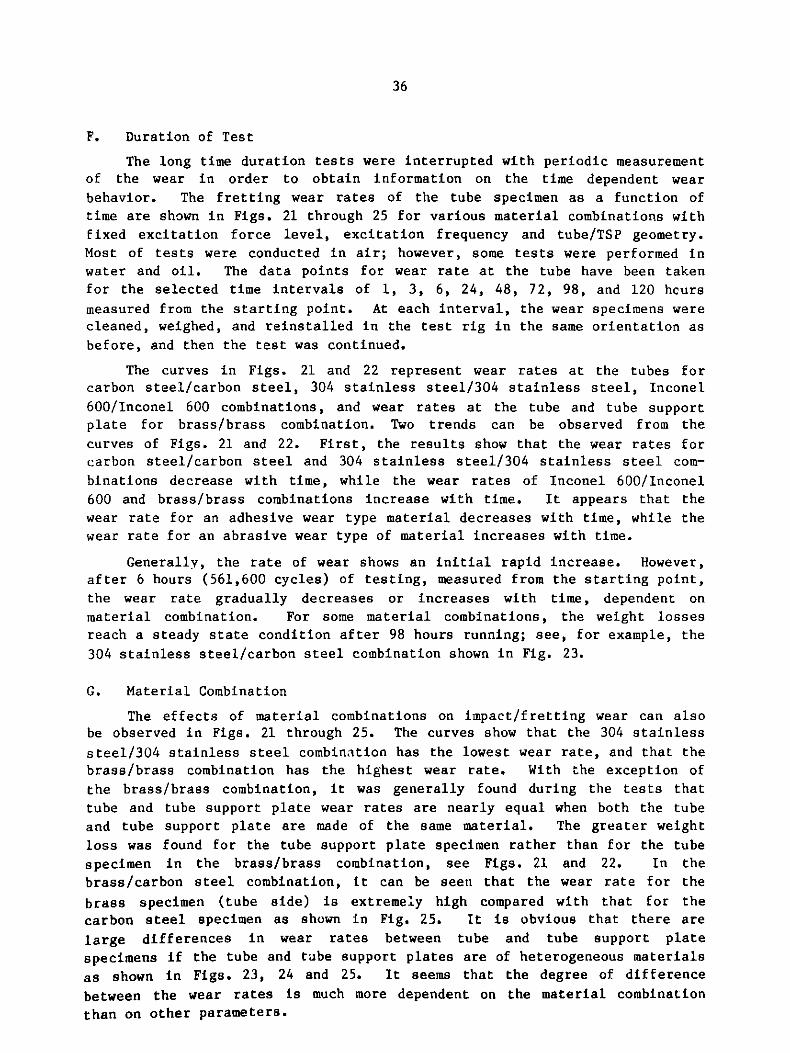
F. Duration of Test
The long time duration tests were interrupted with periodic measurement
of the wear in order to obtain information on the time dependent wear
behavior. The fretting wear rates of the tube specimen as a function of
time are shown in Figs. 21 through 25 for various material combinations with
fixed excitation force level, excitation frequency and tube/TSP geometry.
Most of tests were conducted in air; however, some tests were performed in
water and oil. The data points for wear rate at the tube have been taken
for the selected time intervals of 1, 3, 6, 24, 48, 72, 98, and 120 hcurs
measured from the starting point. At each interval, the wear specimens were
cleaned, weighed, and reinstalled in the test rig in the same orientation as
before, and then the test was continued.
The curves in Figs. 21 and 22 represent wear rates at the tubes for
carbon steel/carbon steel, 304 stainless steel/304 stainless steel, Inconel
600/Inconel 600 combinations, and wear rates at the tube and tube support
plate for brass/brass combination. Two trends can be observed from the
curves of Figs. 21 and 22. First, the results show that the wear rates forcarbon steel/carbon steel and 304 stainless steel/304 stainless steel com-
binations decrease with time, while the wear rates of Inconel 600/Inconel
600 and brass/brass combinations increase with time. It appears that the
wear rate for an adhesive wear type material decreases with time, while the
wear rate for an abrasive wear type of material increases with time.
Generally, the rate of wear shows an initial rapid increase. However,
after 6 hours (561,600 cycles) of testing, measured from the starting point,
the wear rate gradually decreases or increases with time, dependent on
material combination. For some material combinations, the weight lossesreach a steady state condition after 98 hours running; see, for example, the
304 stainless steel/carbon steel combination shown in Fig. 23.
G. Material Combination
The effects of material combinations on impact/fretting wear can also
be observed in Figs. 21 through 25. The curves show that the 304 stainless
steel/304 stainless steel combination has the lowest wear rate, and that the
brass/brass combination has the highest wear rate. With the exception of
the brass/brass combination, it was generally found during the tests that
tube and tube support plate wear rates are nearly equal when both the tube
and tube support plate are made of the same material. The greater weight
loss was found for the tube support plate specimen rather than for the tube
specimen in the brass/brass combination, see Figs. 21 and 22. In the
brass/carbon steel combination, it can be seen that the wear rate for the
brass specimen (tube side) is extremely high compared with that for the
carbon steel specimen as shown in Fig. 25. It is obvious that there are
large differences in wear rates between tube and tube support plate
specimens if the tube and tube support plates are of heterogeneous materials
as shown in Figs. 23, 24 and 25. It seems that the degree of difference
between the wear rates is much more dependent on the material combination
than on other parameters.

37
300
200 BRASS (TSP)
BRASS
100
50
z0
J
3 INCONEL 600
4 20ac
J
10 CARBON STEEL
304 SS~
5--
2I
0 24 48 72 96 1'20
T EST DUR ATION, hour
Fig. 21. Wear Rate as a Function of Test Duration, Excitation Force:
6.14 N, Frequency: 26 Hz, Tube/TSP Clearance (diametral):
0.78 mm, TSP Thickness: 14.27 mm, Preload: None

38
300
200- 200 BRASS (TSP)
100 -- BRASS _
50z
I NCONEL 600
20--
10
CARBON STEEL
- 5-
w 304 SS
2--
S2
I0
0 24 48 72 96 120
TEST DURATION, hour
Fig. 22. Wear Rate as a Function of Test Duration, Excitation Force:
6.14 N, Frequency, 26 Hz, Tube/TSP Clearance (diametral):0.78 mm, TSP Thickness: 14.27, Preload: 5.56 N

39
10
W
J
CARBON STEEL (TSP)
U
0 . -
J 2
J
1L0
I- 304 SS (TUBE)
0.2
0.I
0 24 48 72 96 !20TEST DURATION, hour
Fig. 23. Wear Rate with Test Duration for Carbon Steel/304 Stainless
Steel Combination, Excitation Force: 6.14 N, Frequency: 26 Hz,Tube/TSP Clearance (diametral): 0.78 mm, TSP Thickness: 14,27 mm,Preload: 5.56 N

40
100
0
50 CARBON STEEL (TSP)o z
Q J
a ~INCONEL 600 (TUBE)
$ 20
10
0 24 48 72 96 120TEST DURATION, hour
Fig. 24. Wear Rate with Test Duration for Carbon Steel/Inconel 600
Combination, Excitation Force: 6.14 N, Frequency: 26 Hz,Tube/TSP Clearance (diametral): 0.78 mm, TSP Thickness:14.27 mm, Preload: None

41
100
BRASS (TUBE)
50U)
z
-s 20-J0~1
J 0244729 2
JJ
u 5
2
CARBON STEEL (TSP)
0 24 48 72 96 120TEST DURATION, hour
Fig. 25. Wear Rate with Test Duration for Carbon Steel/Brass Combination,Excitation Force: 6.14 N, Frequency: 26 Hz, Tube/TSP Clearance(diametral): 0.78 mm, TSP Thickness: 14.27 mm, Preload: 5.56 N
42
When the tube and tube support plate are of same material, noconsistent patterns emerged relative to the effect of material hardness.
For example, while Inconel 600 has a higher hardness than 304 stainless
steel and carbon steel, the wear rate of Inconel 600 is higher compared with
both 304 stainless steel and carbon steel. However, there is evidence of
material hardness effects when heterogeneous material combinations are used;
for example, in the Inconel 600/carbon steel combination (Fig. 24), carbon
steel, which has a lower hardness, exhibits a higher wear rate than the
higher hardness material, Inconel 600.
In these tests, 304 stainless steel/carbon steel is shown to representthe best material combination. From the impact/fretting wear point of view,
the selection of the tube and tube support plate material combination is a
very important consideration in the design of heat exchangers.
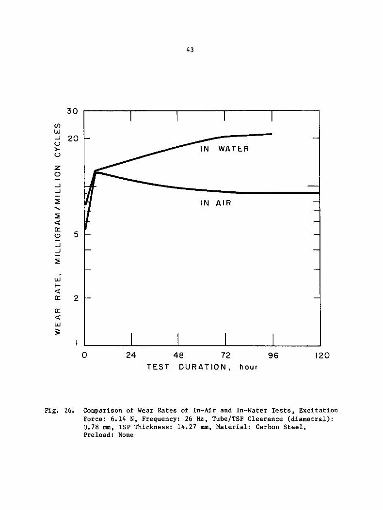
H. Liquid Environment
Impact/fretting wear rates were measured with the specimens submergedin tap water. Comparisons between impact/fretting wear rates measured in-
air and in-water at room temperature can be made in Figs. 26 (no preload)
and 27 (with preload). These figures indicate that the wear rate in water
is higher than that in air for the same test parameters. It should be noted
that the wear rate in water without preload is much higher than the case
with preload.
During the in-water tests, a strong pumping effect was observed in the
gap between the tube and tube support plate hole. A heavy rusting
phenomenon was observed in the water tests. There are no comparison data on
the effect of an aqueous fluid on the amount of fretting wear. The
accelerated wear may be associated with a washing effect that serves to more
easily disperse the debris into the water, as Waterhouse [15] predicts.
An in-oil test using carbon steel/carbon steel combination specimenswas attempted with the same parameters as used in the in-water tests. Oil
(TEXACO R&O 150) with a kinematic viscosity of 9.85 x 10⁻⁵ m2/sec at atemperature of 45*C was used. During the first several hours of testing,
measurable, but very small, weight loss was observed. However, no
quantitative wear was observed during the next 48 hours of testing. The oil
obviously acts as a lubricant, as well as a damping fluid. Jendrzejczyk
[16] has reported a larger damping ratio in oil than in water for tests
associated with a study of tube to tube support plate interactiondynamics. Wear can be greatly reduced by proper lubrication, especially
when a full hydrodynamic oil film is achieved in the gap between the
surfaces of two bodies.
IV. DISCUSSION
Fretting wear is defined as the removal or displacement of material
from surfaces of bodies in relative motion by mechanical or mechanical/
chemical processes. Wear of metals is a complex phenomenon. In the past,
43
30
U
-20-
0z
-J
IN AIR
-J
r 2
cr
0 24 48 72 96 120TEST DURATION, hour
Fig. 26. Comparison of Wear Rates of In-Air and In-Water Tests, Excitation
Force: 6.14 N, Frequency: 26 Hz, Tube/TSP Clearance (diametral):0.78 mm, TSP Thickness: 14.27 mm, Material: Carbon Steel,Preload: None

44
20
10
5
2
0 24 48 72TEST DURATION,
96 120hour
Fig. 27. Comparison of Wear Rates of In-Air and In-Water Tests, Excitation
Force: 6.14 N, Frequency: 26 Hz, Tube/TSP Clearance (diametral):0.78 mm, TSP Thickness: 14.27 mm, Material: Carbon Steel,
Preload: 5.56 N
w
0
z
-J-J
(9-J
-J
wU
3-
IN WATER _
. IN AIR
45
various wear mechanisms have been considered: adhesive, abrasive, diffusive,
corrosive, fatigue and fretting. The existence of abrasive, diffusive and
corrosive wear mechanisms has been reasonably well established, however, the
mechanisms of adhesive, fatigue and fretting wear are not clearly understood
yet. Fretting wear is a combination of adhesive, abrasive and corrosive
mechanisms, and is often connected with the appearance of surface fatigue.
Several investigators have described the possible processes involved in
fretting wear. For example, Waterhouse [17] presented the following steps:
removal of metal from the surfaces by mechanical grinding action or by
formation of welds followed by tearing; oxidation of the metal particles
into an abrasive powder which continues the action; oxidation of the metal
surface; and continual removal of the oxide layer with fresh metal beingexposed. Hurricks [18] described the fretting wear process in the following
three steps: (1) initial adhesion and metal transfer; (2) production of
debris in a normally oxidized state; and (3) steady-state wearing.
Based on the results of these experiments, various time-dependent
stages in the fretting wear process can be proposed. It seems that the wear
process consists of the following stages: initial preparatory stage for wear
formation by the oscillating impact force; transient stage involving plastic
deformation, metal transfer, and oxidization; and stable (steady state)
stage for continuous generation of wear debris.
The results of Figs. 21 and 22 show that the wear rate associated withthe inital stage, consisting of several thousands cycles, is very low. Once
two metallic surfaces are brought into contact under oscillating impact
conditions, they are initially protected by an oxide-metal surface layer.
This oxide layer can act as a solid lubricant film in preventing metal-to-
metal contact. During the initial period, it is believed that there is a
pile-up of dislocations a finite depth below the surface. Suh [19] suggeststhat this leads to the formation of voids, to the coalescence of the voids
by shearing of the metal, and, ultimately, to plastic deformation. In the
transient stage, the apparent virgin material is deformed at the surface;
the adhesion and metal transfer processes then follow. The disruption of
the protective oxide film allows the oxidation of next layer to occur. Due
to break-up of the surface by severe surface fatigue, the wear rate ishigher during this period. The degree of plastic deformation and adhesion
depends on the impact force and on the metallurgical properties of the
materials. After the transient period, the wear rate stabilizes. The
stable state is defined as that point in the wear process at which the lossof debris from the specimen boundaries is a constant with time.
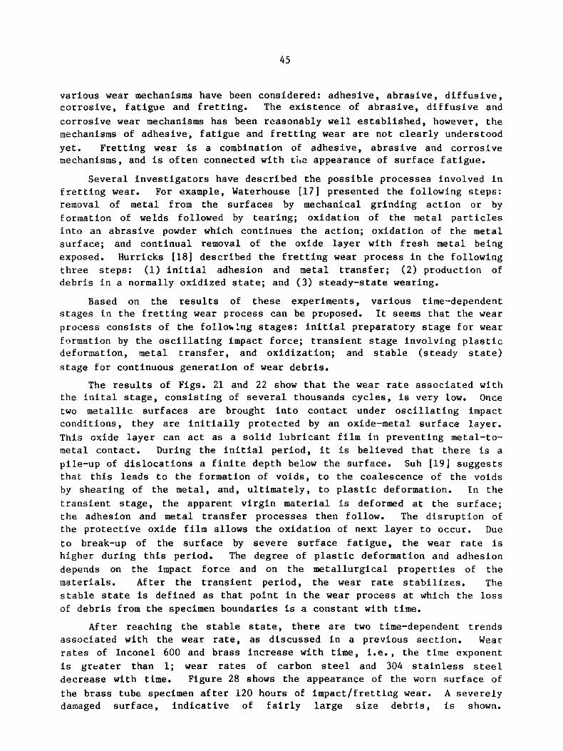
After reaching the stable state, there are two time-dependent trends
associated with the wear rate, as discussed in a previous section. Wear
rates of Inconel 600 and brass increase with time, i.e., the time exponent
is greater than 1; wear rates of carbon steel and 304 stainless steel
decrease with time. Figure 28 shows the appearance of the worn surface of
the brass tube specimen after 120 hours of impact/fretting wear. A severely
damaged surface, indicative of fairly large size debris, is shown.

'M -
y -J 4
4
4 -'f t r 1. d
,R -" A ,
11 y/ S "M.Yr F .( ",Se, "t ~ i r. f.: .-
Fig. 28. Appearance of a Worn Tube Specimen (ANL Neg. No. 113-85-14)
tp-a'
.4
tvr<!C
47
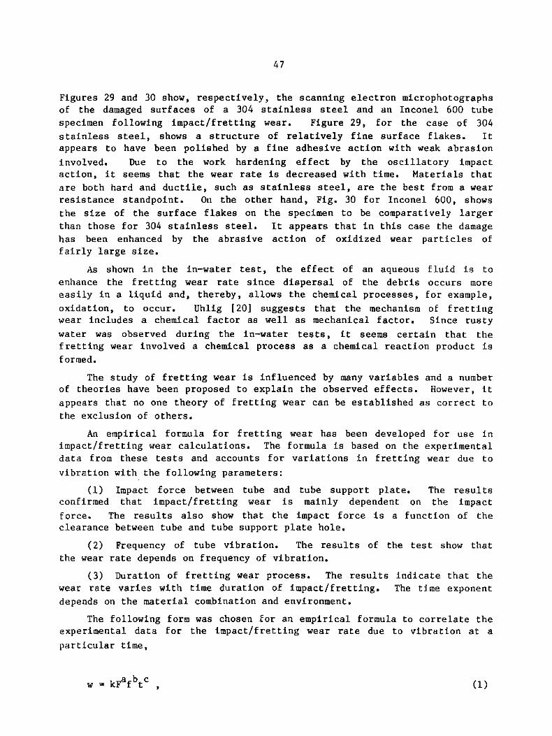
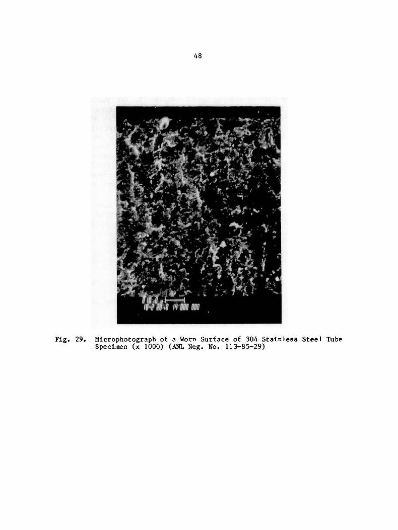
Figures 29 and 30 show, respectively, the scanning electron microphotographs
of the damaged surfaces of a 304 stainless steel and an Inconel 600 tube
specimen following impact/fretting wear. Figure 29, for the case of 304
stainless steel, shows a structure of relatively fine surface flakes. Itappears to have been polished by a fine adhesive action with weak abrasion
involved. Due to the work hardening effect by the oscillatory impactaction, it seems that the wear rate is decreased with time. Materials that
are both hard and ductile, such as stainless steel, are the best from a wearresistance standpoint. On the other hand, Fig. 30 for Inconel 600, shows
the size of the surface flakes on the specimen to be comparatively largerthan those for 304 stainless steel. It appears that in this case the damage
has been enhanced by the abrasive action of oxidized wear particles offairly large size.
As shown in the in-water test, the effect of an aqueous fluid is to
enhance the fretting wear rate since dispersal of the debris occurs more
easily in a liquid and, thereby, allows the chemical processes, for example,
oxidation, to occur. Uhlig [20] suggests that the mechanism of fretting
wear includes a chemical factor as well as mechanical factor. Since rusty
water was observed during the in-water tests, it seems certain that thefretting wear involved a chemical process as a chemical reaction product is
formed.
The study of fretting wear is influenced by many variables and a numberof theories have been proposed to explain the observed effects. However, it
appears that no one theory of fretting wear can be established as correct to
the exclusion of others.
An empirical formula for fretting wear has been developed for use inimpact/fretting wear calculations. The formula is based on the experimental
data from these tests and accounts for variations in fretting wear due to
vibration with the following parameters:
(1) Impact force between tube and tube support plate. The resultsconfirmed that impact/fretting wear is mainly dependent on the impact
force. The results also show that the impact force is a function of the
clearance between tube and tube support plate hole.
(2) Frequency of tube vibration. The results of the test show that
the wear rate depends on frequency of vibration.
(3) Duration of fretting wear process. The results indicate that thewear rate varies with time duration of impact/fretting. The time exponent
depends on the material combination and environment.
The following form was chosen for an empirical formula to correlate the
experimental data for the impact/fretting wear rate due to vibration at a
particular time,
w = kFafbtc (1)
48
Fig. 29. Microphotograph of a Worn Surface of 304 Stainless Steel TubeSpecimen (x 1000) (ANL Neg. No. 113-85-29)

49
Fig. 30. Microphotograph of a Worn Surface of Inconel 600Tube Specimen (x 1000) (ANL Neg. No. 113-85-30)

50
where w is the wear rate (mg/106 cycles) at time t (hour) from starting
point, F is the resultant impact force between the tube and tube support
plate (N), f is the frequency of vibration (Hz), and k, a, b, and c are
empirically derived constants. This relationship includes the dependence of
wear rate on impact force between the wear couple, the frequency of
vibration, and the wear processing time.
For a particular frequency of vibration, the wear rate at a selected
time from the start of the wear process, can simply be expressed as
w = k'Fa , (2)
where k' is constant.
Generally, impact force F is a function of excitation force E and
clearance between tube and tube support plate hole Cd, i.e.,
F o EdeC ,
where d and e are empirically derived constants.
Equation (1) does not include the amplitude of vibration since its
magnitude is equivalent to the magnitude of the clearance between the wear
couple as long as contact between the two bodies is occurring. The
constants k and c are mainly dependent on the material combination and the
environment.
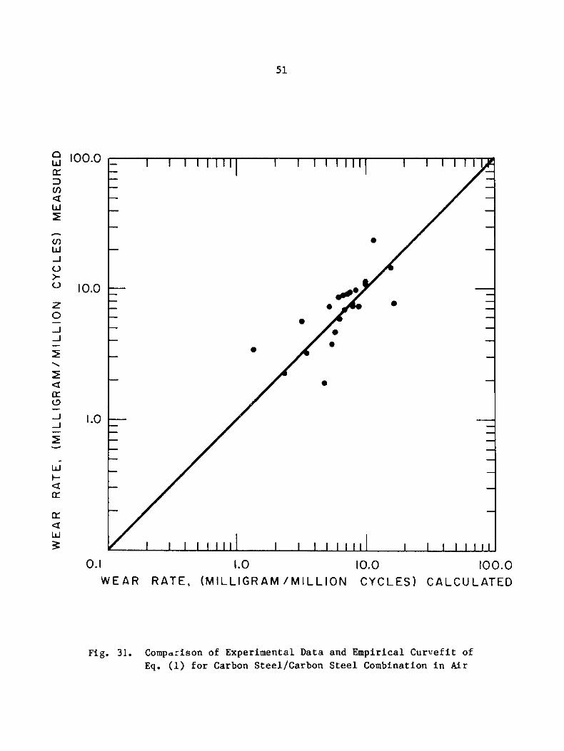
For a particular material combination and environment, the constants in
Eq. (1) can be derived by fitting the experimental data. As an example, for
the wear rate of carbon steel in air, the following constants were obtained:
k = 0.8 (g-N 1h~1cycle-2), a = 1.72, b = -1, c = -0.23. This curve fit is
compared with the experimental data in Fig. 31.
V. CONCLUSIONS
A series of tests has been performed with the objective to further the
understanding of impact/fretting wear of a heat exchanger tube vibrating
within a tube support plate hole. Tests were conducted in air, water, and
oil, at room temperature. Wear was measured by a weight loss technique and
wear rate was calculated.
The principal results of the tests are: (1) Wear rate increases with
tube support impact force; (2) The degree of wear rate is strongly dependent
on the metallurgical characteristics of the materials (for example, 304
stainless steel as a tubing material is superior to others with respect to
wear resistance); (3) Wear rate is time dependent (for example, for the same
excitation conditions, the wear rate of 304 stainless steel decreases with
51
100.0
10.0
1.0
0.1 1.0WEAR RATE, (MILLIGRAM
10.0/MILLION CYCLES)
100.0CALCUL ATED
Fig. 31. Comparison of Experimental Data and Empirical Curvef it ofEq. (1) for Carbon Steel/Carbon Steel Combination in Air
0
U)
w
U)
LU-
0
z
-J-J
wI--
c-J
cr
Lw~
0"
"
0
52
time, whereas Inconel 600 shows an increase); (4) Impact/fretting wear rate
decreases with increasing excitation frequency for a fixed impact force
level at the support; (5) The wear rate for carbon steel in water is greater
than that in-air, on the other hand, the wear rate in oil is very much lowerthan that for other materials; (6) Wear rate decreases with preload of the
tube against 4ie support.
Further investigations are needed to: (1) identify and characterize the
wear producing impact force in real heat exchangers; (2) generate and
characterize more basic wear data on various material combinations of tube
and tube support plate, (3) generate data under operating conditions
(temperature and pressure) using autoclaves.
ACKNOWLEDGMENTS
The work was made possible through the support of the Korea Science andEngineering Foundation and was performed as part of a Program of Shell and
Tube Heat Exchanger Research sponsored by the U.S. DOE Office of Energy
Systems Research, Energy Conversion and Utilization Technolog?es Division.
The authors wish to thank Dr. H. M. Chung for his assistance inproviding the scanning electron microphotographs.

53
REFERENCES
1. H. Halle, J. M. Chenoweth, and M. W. Wambsganss, "DOE/ANL/HTRI Heat
Exchanger Tube Vibration Data Bank," ANL-CT-80-3, Addenda 1-4, 1981-1983.
2. I-Ming Feng and Herbert H. Unlig, "Fretting Corrosion of Mild Steel inAir and in Nitrogen," J. of Applied Mechanics, Vol. 21, Trans. ASME,Vol. 86, pp. 395-400, 1954.
3. P. L. Ko, "Experimental Studies of Tube Frettings in Steam Generators
and Heat Exchangers," Trans. ASME, J. of Pressure Vessel Technology,
Vol. 101, pp. 125-133, 1979.
4. R. D. Blevins, "Fretting Wear of Heat Exchanger Tubes, Part 1:Experiments," Trans. ASME, J. of Engineering for Power, Vol. 101, pp.625-629, 1979.
5. R. D. Blevins, "Vibration-Induced Wear of Heat Exchanger Tubes," Trans.ASME, J. of Engineering Materials and Technology, Vol. 107, pp. 61-67,1985.
6. S. S. Chen, G. S. Rosenberg, and M. W. Wambsganss, "On Tube-BaffleImpact During Heat Exchanger Tube Vibrations," Proc. ASME Symp. Flow-
Induced Vibration in Heat Exchangers, New York, pp. 28-35, 1970.
7. Y. S. Shin, D. E. Sass, and J. A. Jendrzejczyk, "Vibro-Impact Responses
of a Tube with Tube-Baffle Interaction," Trans. CSME, Vol. 5, pp.15-23, 1979.
8. R. J. Rogers and R. J. Pick, "On the Dynamic Spatial Response of a HeatExchanger Tube with Intermittent Baffle Contacts," Nucl. Eng. Des.,
Vol. 36, pp. 81-90, 1976.
9. R. J. Rogers and R. J. Pick, "Factors Associated with Support PlateForces Due to Heat Exchanger Tube Vibration Contact," Nucl. Eng. Des.,
Vol. 44, pp. 247-253, 1977.
10. F. Axisa, A. Desseaux, and R. J. Gilbert, "Experimental Study of
Tube/Support Impact Forces in Multi-span PWR Steam Generator Tubes,"ASME Symposium on Flow-Induced Vibrations, Vol. 3, pp. 139-148, 1984.
11. T. M. Frick, T. E. Sobek, and J. R. Reavis, "Overview on theDevelopment and Implementation of Methodologies to Compute Vibration
and Wear of Steam Generator Tubes," ASME Symposium on Flow-Induced
Vibrations, Vol. 3, pp. 149-161, 1984.
12. "Standards of Tubular Exchanger Manufacturers Associates," SixthEdition, 1978.
13. M. W. Wambsganss, H. Halle, and W. P. Lawrence, "Tube Vibration inIndustrial Size Test Heat Exchanger (300 Triangular Layout - Six
Crosspass Configuration), ANL Technical Memorandum, ANL-CT-81-42, 1981.
54
14. H. Halle, Components Technology Division, Argonne National Laboratory,Private Communication, 1984.
15. R. B. Waterhouse, "Fretting in Hostile Environments," Wear, Vol. 34,pp. 301-309, 1975.
16. J. A. Jendrzejczyk, "Dynamic Characteristics of Heat Exchanger TubesVibrating in a Tube Support Plate Inactive Mode," ANL-84-39, 1984.
17. R. B. Waterhouse, "Fretting Corrosion," Pergamon Press, Oxford, 1972.
18. P. L. Hurricks, "The Mechanism of Fretting - A Review," Wear, Vol. 15,pp. 389-409, 1970.
19. Nam P. Suh, "The Delamination Theory of Wear," Wear, Vol. 25, pp.111-124, 1973.
20. Herbert H. Uhlig, "Mechanism of Fretting Corrosion," Trans. ASME, J. ofApplied Mechanics, Vol. 21, pp. 401-407, 1954.

55
Distribution for ANL-85-38
Internal:
J. J. RobertsR. S. ZenoM. W. Wambsganss (50)R. E. HoltzM. J. BernardE. F. Bielick
S. S. ChenH. H. ChungH. M. Chung
H. HalleJ. A. JendrzejczykT. M. MulcahyY. W. ShinS. K. ZussmanANL Patent Dept.ANL Contract FileANL LibrariesTIS Files (6)
External:
DOE-TIC (30)Manager, Chicago Operations Office, DOEDirector, Technology Management Div., DOE-CHD. L. Bray, DOE-CHComponents Technology Division Review Committee:
P. Alexander, Flopetrol Johnston Schlumberger, Houston, TXD. J. Anthony, General Electric Co., San Jose, CAA. Bishop, U. PittsburghB. A. Boley, Northwestern U.F. W. Buckman, Delian Corporation, Monroeville, PAR. Cohen, Purdue U.J. Weisman, U. Cincinnati