Embed Size (px)
Citation preview

8/3/2019 amx 1Y.InstructionManual
http://slidepdf.com/reader/full/amx-1yinstructionmanual 1/82
1Y Series Documentation
1Y Series User’s Reference Manual, Order #13–819
q For All 1Y Series Distribution Matrices
Level Jumper Settings Supplement
q Provides further clarification for the procedure on defining levels

8/3/2019 amx 1Y.InstructionManual
http://slidepdf.com/reader/full/amx-1yinstructionmanual 2/82
1Y Series DistributionMatrices
User Reference Manual
CPU Version 5.0
Document VersionA4

8/3/2019 amx 1Y.InstructionManual
http://slidepdf.com/reader/full/amx-1yinstructionmanual 3/82
Notices
AutoPatch © 1994, 1997, 1998 all rights reser ved. No part of this pu blicat ion m ay be reproduced,stored in a retrieval system, or transmitted, in any form or by any means, electronic, mechanical,photocopying, recording, or otherwise, without th e prior wr itten perm ission of AutoPa tch. Copy-
right protection claimed extends to the AutoPatch 1YDM hardware and software and includes allforms and matters, copyrightable material and information now allowed by statutory or judiciallaw or herein after granted, including without limitation, material generated from the softwareprograms which are displayed on t he screen s uch as icons, screen display looks, etc.... Reproduc-tion or disassembly of embodied computer programs or algorithms is expressly prohibited.
No patent liability is assumed with respect to the use of information contained herein.
While every precaution has been taken in the preparation of this publication, AutoPatch assumesno responsibility for error or omissions. No liability is assu med for da ma ges resulting from th e useof the information contained herein.
Further, this publication and features described herein are subject to change without notice.
The United States Federal Communications Commission (in 47CFR 15.838) has specified that thefollowing notice be brought to th e at tent ion of the u sers of this product.
Federal Communication Commission Radio Frequency Interference Statement“This equipment generates and uses radio frequency energy and if not installedan d used properly, tha t is, in str ict accorda nce with t he ma nufactur er’s instr uc-tions, may cause interference to radio and television reception. It h as been type-tested and found to comply with the limits for a Class B computing device in ac-cordance with the specifications in Subpart J of Part 15 of FCC Rules, which aredesigned to provide reasonable protection against such interference in a residen-tial insta llation. However th ere is no guar an tee tha t inter ference will not occurin a part icular installation. If this equipment causes interference to radio or tele-vision reception, which can be determined by turning the equipment on and off,the user is encouraged to try to correct the interference by one or more of the fol-lowing measures:
» Re-orient the receiving antenn a
» Relocate the matrix with r espect to the receiver
» Move the mat rix away from the receiver
» Plug the distribution mat rix into a different outlet so that computer a ndreceiver are on different branch circuits
If necessary, the user should consult the dealer or an experienced radio/televisiontechnician for additional suggestions. The user ma y find the booklet, How to
Identify and Resolve Radio-TV Interference Problems, prepared by the FederalComm unications Commissions t o be helpful."
This booklet is available from t he U S. Governm ent Pr inting Office, Washington, D.C. 20402, Stock N. 004-000-00345-4.
Use shielded cables. To comply with F CC Class B r equirement s, all extern al data inter face cablesand ada pters mu st be shielded.
AutoPatch 1Y Series Distribution Matrix product specifications are available upon request, or byvisiting our website a t: h tt p://www.autopatch.com
DOS and Windows are registered trademarks of Microsoft Corporation.

8/3/2019 amx 1Y.InstructionManual
http://slidepdf.com/reader/full/amx-1yinstructionmanual 4/82
AutoPatch Statement of Warranty
AutoPatch, a division of XN Technologies, Inc., Cheney, Wash ington, warr ant ees th at the productsmanufactured by AutoPatch will be free of defects in materials and workmanship for the lifetime of the product, subject t o the following term s a nd conditions.
Terms and Conditions
1. AutoPatch pr oducts a re u nder warr an ty for a period of five (5) years following the
original sales invoice dat e. The war ra nty p eriod m ay be extended to th e life of th e
product provided the warranty card is filled out and returned to AutoPatch. TO
VALIDATE THE LIFETIME WARRANTY: THE AutoPatch WARRANTY CARD
MUST BE FILLED OUT BY THE DEALER AND RECEIVED BY AutoPatch
WITHIN THIRTY (30) DAYS OF THE INSTALLATION OF EQUIPMENT BUT NO
LATER TH AN ONE (1) YEAR FROM TH E ORIGINAL SALES INVOICE DATE. A
warranty certificate will be returned to the dealer to verify the warranty period.
2. This Limited Lifetime warra nty covers AutoPa tch products shipped on or after October 1,1997. The Limited Lifetime warranty applies to products in the original installation only. If
the product is moved to a different installation, the Limited Lifetime warranty will no longerapply and the product warranty will revert tot he original warranty which covers a period of five (5) years following the original sales invoice date.
3. The product lifetime is defined as t he period of time from th e originalsales invoice date to ten (10) years after AutoPatch ceases manufacturingthe product model.
4. Warran ty repairs ar e accomplished by return ing the subassembly to AutoPatch for r epair. If conditions do not perm it t his pr ocedure, Aut oPatch will invoice new or reconditioned (at Auto-Pa tch’s option) replacement pa rt s and sh ip them t o th e dealer or to the customer if so directedby written order from the dealer. In that case the replacement will be billed to the customerand the customer may return the failed subassembly within 30 days for credit. See “AutoPatchReturns Policy” in this manual for replacement policies and procedures.
5. AutoP atc h’s l i abi l i ty and Bu ye r ’s r e m e di e s u nde r thi s war r anty s ha l l be l i m i te d
s ol e l y to r e pa i r , r e pl ac e m e nt, or c r e di t, at AutoP atc h’s opti on .
6. The AutoPatch warr anty does not a pply to any AutoPat ch pr oduct that has been modified, re-paired by an unauthorized agent, or improperly installed, used, or maintained. AutoPatchshall not be liable under any circumstances for consequential or incidental damages including,but not limited t o, labor costs or loss of profits a rising in connection with t he u se of or in abilityto use AutoPatch products.
7. AutoPatch will not be responsible for items dama ged during shipment t o or from AutoPatch.The shipping carrier is responsible for items damaged during shipment.
8. This warr ant y is exclusive and in lieu of any other war ra nt y, expressed or implied, includingbut not limited to any implied merchantability or fitness for a particular purpose. The terms of this warr ant y are governed by the laws of the state of Washington; certain other stat es restr ictwarra nty limitations. You m ay ha ve rights tha t a re not defined herein.
9. This warr ant y may not be modified except in writing by an a uth orized Aut oPatch officer.

8/3/2019 amx 1Y.InstructionManual
http://slidepdf.com/reader/full/amx-1yinstructionmanual 5/82
TABLE OF CONTENTSIntroduction
How to Use This Manual. . . . . . . . . . . . . . . . . . . . . . . . . . . . . . . . . ii
Typographical Conventions . . . . . . . . . . . . . . . . . . . . . . . . . . . . . . iii
Definition of Terms Used in This Manual . . . . . . . . . . . . . . . . . . . . . . . iii
Technical Support. . . . . . . . . . . . . . . . . . . . . . . . . . . . . . . . . . . . iv
Chapter 1—Getting Started
Unpacking the 1YDM . . . . . . . . . . . . . . . . . . . . . . . . . . . . . . . . . 1-2
Possible Installation Sites . . . . . . . . . . . . . . . . . . . . . . . . . . . . . . 1-3Linking Enclosures . . . . . . . . . . . . . . . . . . . . . . . . . . . . . . . . . . 1-3
Setting Master and Slave Enclosures . . . . . . . . . . . . . . . . . . . . . . . . 1-5
Defining Levels . . . . . . . . . . . . . . . . . . . . . . . . . . . . . . . . . . . . 1-5
Attaching Inputs and Outputs . . . . . . . . . . . . . . . . . . . . . . . . . . . . 1-7
Applying Power . . . . . . . . . . . . . . . . . . . . . . . . . . . . . . . . . . . . 1 -8
Startup Sequence . . . . . . . . . . . . . . . . . . . . . . . . . . . . . . . . . . . 1-8
Adding Input/Output (I/O) Boards . . . . . . . . . . . . . . . . . . . . . . . . . . 1-9
Adjusting Gain Control . . . . . . . . . . . . . . . . . . . . . . . . . . . . . . 1-10
Chapter 2—Operating the Distribution Matrix
Making a Switch . . . . . . . . . . . . . . . . . . . . . . . . . . . . . . . . . . . . 2-1
Checking Status . . . . . . . . . . . . . . . . . . . . . . . . . . . . . . . . . . . . 2-2
Disconnecting a Signal on a Level . . . . . . . . . . . . . . . . . . . . . . . . . . 2-3
Disconnecting a Signal Using QuickDis . . . . . . . . . . . . . . . . . . . . . . . 2-3
Using Presets . . . . . . . . . . . . . . . . . . . . . . . . . . . . . . . . . . . . . 2 -4
Dry Contacts and Presets. . . . . . . . . . . . . . . . . . . . . . . . . . . . . . . . . . 2-5
Changing the Configuration Word . . . . . . . . . . . . . . . . . . . . . . . . . . 2-6
Control Panel Echo . . . . . . . . . . . . . . . . . . . . . . . . . . . . . . . . . . . . . 2 -6
Serial Status Filter . . . . . . . . . . . . . . . . . . . . . . . . . . . . . . . . . . . . . . 2 -7
16x16 Front Panel Attached . . . . . . . . . . . . . . . . . . . . . . . . . . . . . . . . 2-7
Sync Board Enable . . . . . . . . . . . . . . . . . . . . . . . . . . . . . . . . . . . . . 2-7
Serial Port 1 . . . . . . . . . . . . . . . . . . . . . . . . . . . . . . . . . . . . . . . . . 2-7
Serial Port 2 . . . . . . . . . . . . . . . . . . . . . . . . . . . . . . . . . . . . . . . . . 2-7
Single Bus Controller (SBC) Polling Limit . . . . . . . . . . . . . . . . . . . . . . . . . 2-8
Control Panel Configuration Scan (CPCS) . . . . . . . . . . . . . . . . . . . . . . . . 2-9
Control Panel Configuration . . . . . . . . . . . . . . . . . . . . . . . . . . . . . . . 2-10
Defining LevelsSupplement

8/3/2019 amx 1Y.InstructionManual
http://slidepdf.com/reader/full/amx-1yinstructionmanual 6/82
Setting the Configuration Word. . . . . . . . . . . . . . . . . . . . . . . . . . . . . . 2-10
Chapter 3—Programming the Matrix
Basic Control Structure (BCS) Language . . . . . . . . . . . . . . . . . . . . . . 3-1
Entering BCS Commands . . . . . . . . . . . . . . . . . . . . . . . . . . . . . . . 3-2
Changing the Configuration Word Using BCS Commands. . . . . . . . . . . . . 3-3
BCS Software Handshaking . . . . . . . . . . . . . . . . . . . . . . . . . . . . . 3-4
Chapter 4—Options
Vertical Interval Sync Expansion Boards . . . . . . . . . . . . . . . . . . . . . . 4-1
Parts of the Sync Board. . . . . . . . . . . . . . . . . . . . . . . . . . . . . . . . . . . 4-3
On Board Jumper Settings . . . . . . . . . . . . . . . . . . . . . . . . . . . . . . . . . 4-4
Installing a Sync Board . . . . . . . . . . . . . . . . . . . . . . . . . . . . . . . . . . . 4-6
Enabling a Sync Board . . . . . . . . . . . . . . . . . . . . . . . . . . . . . . . . . . . 4-6
Pluggable Connectors on Audio Boards. . . . . . . . . . . . . . . . . . . . . . . 4-6
Front Panel . . . . . . . . . . . . . . . . . . . . . . . . . . . . . . . . . . . . . . . 4-7
Local X/Y Control Panel . . . . . . . . . . . . . . . . . . . . . . . . . . . . . . . . . . . 4-7
Remote X/Y Control Unit . . . . . . . . . . . . . . . . . . . . . . . . . . . . . . . . . . 4-9
Blank Front Panel . . . . . . . . . . . . . . . . . . . . . . . . . . . . . . . . . . . . . 4-10
Using External Controllers . . . . . . . . . . . . . . . . . . . . . . . . . . . . . 4-11
Attaching an External Controller . . . . . . . . . . . . . . . . . . . . . . . . . . . . . 4-11
Using a Dumb Terminal . . . . . . . . . . . . . . . . . . . . . . . . . . . . . . . 4-13
Single Bus Controllers (SBC) . . . . . . . . . . . . . . . . . . . . . . . . . . . . 4-14
Versions . . . . . . . . . . . . . . . . . . . . . . . . . . . . . . . . . . . . . . . . . . 4-14
Models . . . . . . . . . . . . . . . . . . . . . . . . . . . . . . . . . . . . . . . . . . . 4-15
Installation . . . . . . . . . . . . . . . . . . . . . . . . . . . . . . . . . . . . . . . . . 4-16
Polling Single Bus Controllers . . . . . . . . . . . . . . . . . . . . . . . . . . . . . . 4-19
Software. . . . . . . . . . . . . . . . . . . . . . . . . . . . . . . . . . . . . . . . 4-21
YRoute . . . . . . . . . . . . . . . . . . . . . . . . . . . . . . . . . . . . . . . . . . . 4-21
WinRoute . . . . . . . . . . . . . . . . . . . . . . . . . . . . . . . . . . . . . . . . . . 4-21
AutoRoute Event Scheduler . . . . . . . . . . . . . . . . . . . . . . . . . . . . . . . . 4-21
ScanPatch . . . . . . . . . . . . . . . . . . . . . . . . . . . . . . . . . . . . . . . . . 4-22
Chapter 5—The Enclosure and Its Parts
Front of an Enclosure . . . . . . . . . . . . . . . . . . . . . . . . . . . . . . . . . 5-1
Change Key . . . . . . . . . . . . . . . . . . . . . . . . . . . . . . . . . . . . . . . . . 5-2
Preset Key . . . . . . . . . . . . . . . . . . . . . . . . . . . . . . . . . . . . . . . . . . 5-2
Matrix Keys . . . . . . . . . . . . . . . . . . . . . . . . . . . . . . . . . . . . . . . . . 5-2
Input Keys . . . . . . . . . . . . . . . . . . . . . . . . . . . . . . . . . . . . . . . . . . 5-2
Output Keys . . . . . . . . . . . . . . . . . . . . . . . . . . . . . . . . . . . . . . . . . 5-3
Cancel Key . . . . . . . . . . . . . . . . . . . . . . . . . . . . . . . . . . . . . . . . . . 5-3
Take Key . . . . . . . . . . . . . . . . . . . . . . . . . . . . . . . . . . . . . . . . . . . 5-3
Rear of an Enclosure . . . . . . . . . . . . . . . . . . . . . . . . . . . . . . . . . 5-3

8/3/2019 amx 1Y.InstructionManual
http://slidepdf.com/reader/full/amx-1yinstructionmanual 7/82
Audio and Video I/O Connectors . . . . . . . . . . . . . . . . . . . . . . . . . . . . . . 5-3
Expansion Slots . . . . . . . . . . . . . . . . . . . . . . . . . . . . . . . . . . . . . . . 5 -4
CPU. . . . . . . . . . . . . . . . . . . . . . . . . . . . . . . . . . . . . . . . . . . . . . 5-4
Rear Main . . . . . . . . . . . . . . . . . . . . . . . . . . . . . . . . . . . . . . . . . . 5-4
I/O Boards . . . . . . . . . . . . . . . . . . . . . . . . . . . . . . . . . . . . . . . 5-4
Impedance Jumpers. . . . . . . . . . . . . . . . . . . . . . . . . . . . . . . . . . . . . 5 -5
Gain Control . . . . . . . . . . . . . . . . . . . . . . . . . . . . . . . . . . . . . . . . . 5-5
Chapter 6—Applications
Paralleling Inputs . . . . . . . . . . . . . . . . . . . . . . . . . . . . . . . . . . . 6-1
Loop Back . . . . . . . . . . . . . . . . . . . . . . . . . . . . . . . . . . . . . . . 6-3
Further Examples Combining Parallel Inputs and Loop Back . . . . . . . . . . . 6-5
Appendix A—AutoPatch Service/Returns Policy
Service . . . . . . . . . . . . . . . . . . . . . . . . . . . . . . . . . . . . . . . A-1
Return Authorizations . . . . . . . . . . . . . . . . . . . . . . . . . . . . . . . A-1
Claims for Shipping Damages . . . . . . . . . . . . . . . . . . . . . . . . . . . A-1
Replacement Policies and Procedures . . . . . . . . . . . . . . . . . . . . . . A-2
Special Notice. . . . . . . . . . . . . . . . . . . . . . . . . . . . . . . . . . . . A-3
Glossary
Index
8/3/2019 amx 1Y.InstructionManual
http://slidepdf.com/reader/full/amx-1yinstructionmanual 8/82
IntroductionThe AutoPatch 1Y Distribution Matrix (1YDM or 1Y) is a sig-
nal switching device that can route audio, video, and data
signa ls. The 1YDM can be cont rolled from a variety of
sources, including a contr ol panel on t he front of an enclosure
(Local X/Y Control Panel), an external controller capable of
sending and receiving information via the serial port, or dry
contacts (switches that are hard wired to the CPU board of an
enclosure and do not require a separate power supply).
1YDM ROM version 5.0 accommodates greater flexibility and
expandability than previous ROM versions. The changes that
occurred between ROM 3.2B and 5.0 include the following:
G A front panel that accommodates 16 inputs and/or 16
outputs
G I/O Boards that accommodate 16 inputs and/or 16
outputs
The 1YDM was designed to accommodate systems using a
limited number of inputs an d outputs. The 1Y uses input/out-
put (I/O) boar ds a s th e switching point for up to 16 signals.
Inputs can only be switched to outputs connected to the same
I/O board a s the input s. The configurat ions (inpu ts x out put s)
available are 4x4, 4x8, 8x8, 12x4, 8x16, 16x8, and 16x16.
The I/O boar ds can be used separa tely or together. Level des-
igna tions on the boards allow you t o group th e boar ds
together or u se them as separate switching environments.
The m atr ix’s CP U ident ifies each board by its level, not its
slot in th e rear of th e enclosure. Four board levels may be
specified for each sepa ra te distribut ion m atr ix. Boar d levels
are par t of the ident ificat ion of signa ls an d a llow virtu ally un-
limited vert ical expansion of the distribut ion m atr ix.
Warning: To avoid E SD (Electr ostatic Discha rge) dama ge to
sensitive components, make sure you are properly
grounded before handling internal boards.
1YDM (ROM version 5.0) specifications are available upon re-
quest, or you can see them on our website at:http://www.autopatch.com.

8/3/2019 amx 1Y.InstructionManual
http://slidepdf.com/reader/full/amx-1yinstructionmanual 9/82
How to Use This Manual
This manu al conta ins six chapters and one appendix. The in-
formation in this manual progresses from unpacking and
installing your distribution matrix in Chapter 1, to applica-
tion techn iques in Chapter 6. Use th e following cha pter
descriptions to guide you through the manual.
Chapter 1 – Installing the Distribution Matrix
Chapter 1 discusses the materials included in the shipping
boxes, what they are used for, and how to install the distribu-
tion ma trix in ma ny types of environments. The startu p
sequence of the 1Y is also discussed in th is cha pter.
Chapter 2 – Operating the Distribution Matrix
The 1YDM is capable of man y variat ions of several basic op-
erations. Chapter 2 explains th e basic operations a nd t heir
variat ions. It also touches on operatin g extern al cont rollers
an d it d iscusses t he configur at ion word.
Chapter 3 – Basic Control Structure Operation Language
Basic Cont rol Stru cture (BCS) is vital t o operat ing your Dis-
tr ibution Mat rix from an exter na l serial cont roller. BCS is a
set of ASCII comman d codes called Basic Contr ol Stru ctu re
(BCS). Chapt er 3 introduces you to BCS and explains how to
use i t .
Chapter 4 – Options
The 1YDM has several optiona l feat ur es an d can be cont rolled
through different control devices.
Chapter 5 – The Enclosure and Its Parts
The en closur e is th e str uctur al basis, or building block, of the
1YDM. An enclosur e is a meta l cha ssis that houses theboards the signal cables are connected to and other vital com-
ponents. Chapter 5 provides a “roadmap” to the importa nt
featu res of 1Y enclosur es an d a description of th e featur e
functions.
Chapter 6 – Applications
Creat ively configuring th e 1YDM adds n ew dimensions to
your system. Chap ter 6 describes some creative ways to con-
figure the distribution matrix and explains how they work to
add flexibility to your system.
Appendix A – AutoPatch Service/Returns Policy
Appendix A presents t he Aut oPatch S ervice/Retur ns Policy.
Please note that if you need to return an enclosure, it should
be ret ur ned in its origina l shipping box if possible.
ii
Introduction

8/3/2019 amx 1Y.InstructionManual
http://slidepdf.com/reader/full/amx-1yinstructionmanual 10/82
Typographical Conventions
In t his man ual, text conventions a re used t o designate par-
ticular meanings, such as key specifications and particular
mat rix operat ions. The convention for X/Y Cont rol Pan el keys
is initial caps an d enclosed in <>’s. For example, “press <Pr e-
set>,” specifies th e key on t he cont rol panel labeled PRE SET.
Nonspecific procedures or component s of the mat rix app ear in
lower case letters. For example, “... to recall a pr eset,
press...,” refers to th e preset procedure, or “... the ma trix
would be...,” refers to an y ma trix.
The convention for specific actions or procedures is initial
caps a nd n um bered, if possible. For example, “Press <Tak e>
to save Preset 4,” or “Matr ix 1 cont rols a ll R signals.”
Notes, warnings, and any t ext tha t requires special attent ion
appears in bold. Note or warn ing para graphs are indented.
Please pay attent ion to any notes and warnings; they are spe-
cifically labeled to designate importance.
Definition of Terms Used in This Manual
Before continuing t o read t his ma nua l you should u nderstan d
a few 1YDM terms that are similar to terms for other Y-series
products except in t heir definitions.
L e v e l - The identifying number of an I/O boar d. More th an
one board can h ave th e sam e level, so component signa ls can
be switched at th e same time. Level is established by setting
the Level pins on the J 1 jumper.
E nc l o s ur e - A metal chassis that houses I/O boards, a CPU,
and a power supply. Enclosures are t he stru ctura l basis of the ma trix. A distribution mat rix can h ave multiple enclo-
sures that can be linked together allowing more input signals
to be switched to more output signals.
D i s t r i but i o n Ma t ri x - The distribution matrix, or matrix, is
the environment of all signals an d th e ha rdware a nd software
necessary to switch these signals. The terms routing
switcher, switching matrix, and routing matrix are also used
commonly in th e au dio/video indu stry to describe a distribu-
tion ma tr ix. The distribution mat rix facilitates th e routing of
an input signal t o no output s, all output s, or any variation of
output s. A matrix must h ave one or more enclosures.
S y s t e m - Must h ave one or more contr ollers an d one or more
matr ix sets.
Local X/Y Control Panel - The panel on the front of the en-
closur e tha t cont ains keys for entering comman ds. The input
and output keys are used for entering inputs an d output s, and
for ma nipulat ing th e configur at ion word.
iii
Introduction

8/3/2019 amx 1Y.InstructionManual
http://slidepdf.com/reader/full/amx-1yinstructionmanual 11/82
E x t e r na l C o nt r o l l e r - An external controller is any device
other than the Local X/Y Control Panel that is used to change
th e inpu t/out put configura tion. Extern al controllers can be
dry contacts, single bus contr ollers (SBC), or a ny device tha t
can send an d receive ASCII code via the serial port. Exam -
ples of extern al cont rollers ar e AutoPatch Single Bus
Controllers, third party control systems, or a PC that uses a
serial communication program to communicate with the dis-
tribution matr ix.
C o nt r o l l e r - A device th at contr ols th e routing of a m at rix. A
controller can be an X/Y Control Panel (remote or local), ex-
ternal serial communications device (RS-232 or RS-422), or
dry cont acts.
Technical Support
AutoPatch pr ovides technical sup port from 6 a.m. t o 5 p.m.
PST Monday-Friday. Before calling with a qu estion, please
consult th is manua l first . If the manu al cannot fully answer
your question, call AutoPatch AutoAssist at: (toll free) 800-
622-0246, (intern ational) 509-235-2636, thr ough our BBS a t509-235-9258, or at our web site: www.autopatch.com.
iv
Introduction

8/3/2019 amx 1Y.InstructionManual
http://slidepdf.com/reader/full/amx-1yinstructionmanual 12/82
Chapter 1—Getting StartedA distribution matrix is a signal switching device that has the
ability t o rout e an y of its inpu ts to zero or m ore of its outp uts .
A distribution matrix is made of one or more enclosures that
can route au dio, video, and da ta signals. The enclosur e is the
stru ctura l basis of a distribut ion ma trix. An enclosur e con-
tains a power supply, a CPU board, and the information
necessary to route the signals on the I/O boards contained in
tha t enclosur e or an y linked enclosur e. The 1Y Distribution
Matrix (1YDM) can be controlled from a variety of sources, in-
cluding a control panel on the front of an enclosure (Local X/Y
Control Panel), an external controller that can send and re-
ceive informa tion via t he serial port, or dry cont acts (switchesthat are h ard wired to the CPU board of an enclosure).
This chapt er covers:
G Unpacking the 1YDM
G Possible insta llat ion sites
G Linking enclosures
G Setting Master and Slave Enclosures
G Definin g Levels
G Attaching Inputs and Outputs
G Applying Power
G Start up Sequence
G Adding In put /Outp ut (I/O) Boar ds
G Adjust ing Gain Cont rol

8/3/2019 amx 1Y.InstructionManual
http://slidepdf.com/reader/full/amx-1yinstructionmanual 13/82
1.1 Unpacking the 1YDM
Before opening th e shipping boxes, examine th em for a ny
signs of damage. If a box is partially crush ed or any side has
been broken open, n otify th e sh ipping agency immediat ely.
The sh ipping box cont aining t he m ast er en closure also holds
invoices, instr uctions, extr a fuses, the 1Y Series Distribution
Matrices User Reference Manual, the power cord, an extender
boar d an d tun ing tool, an d other enclosur e products. If your
matrix is comprised of multiple enclosures, each box also con-
ta ins an int er-enclosur e linking cable. The shipping boxes are
ma rked as “Cont ainer #_of_.” The first blan k is for t he box
number and the second blank is for the total number of boxes
in the shipment. The box marked Conta iner #1 holds the
ma ster enclosure. A 2 rack un it (4-slot) enclosure weighs a p-
proximat ely 15 lb. After removing th e ma ster enclosure from
1-2
Chapter 1
AutoPatchTM
1YDM Series
CANCEL T A K E
O U TP U TI NP U TM A TR I X
PRESET CHANGE
Power ON
Rack Mounting Ears
Matrix Keys Input & Output Keys
<Preset>
<Change> <Cancel> <Take>
Power On LED
figure 1.1 Standard 1Y X/Y Control Panel (top), 1Y 16x16 X/Y Control Panel (middle), rear view of 1Y (bottom).Your control panel and matrix may differ from those pictured above.
Serial Ports
Expansion Slots Outputs Inputs
CPU Board
Rear Main
Power Connector
Power Switch Fuse Drawer

8/3/2019 amx 1Y.InstructionManual
http://slidepdf.com/reader/full/amx-1yinstructionmanual 14/82
its box, collect all docum ent at ion an d envelopes. Keep your
shipping boxes in case you need to return the product.
Depending on your m at rix, your Local X/Y Cont rol Pan el may
ha ve a second row of butt ons
N o t e : AutoPatch will not be responsible for dam age to re-
turn ed products incurred dur ing shipping due to in-
sufficient pa ckaging. If requested, Aut oPatch willsupply a new shipping carton at cost.
1.2 Possible Installation Sites
The 1YDM can be installed in a ra ck or on a deskt op. If you
are insta lling the distribution matr ix in a r ack, mount i t in a
standard EIA 19″ (48.26 cm) rack. 4-slot enclosures are 2 rack
un its (3 in. or 7.62 cm) tall. 6-slot en closures ar e 3 r ack un its
(4.75 in. or 12.07 cm) tall. 8-slot enclosures are 4 rack units (6
in. or 15.24 cm) tall.
A distribution matrix with multiple enclosures should be in-stalled in a rack with all the enclosures linked so control
information can travel between them.
If your distribution matrix is made of a single enclosure and
you wish to install it on a desktop, remove the ears on the
sides of the enclosure and place the four rubber pads (in-
cluded in t he sh ipping container) on t he bottom of the
enclosure.
To install a matrix in a rack:
1. Place each enclosure in the rack and att ach front-
mount ing screws to hold it firmly in place.
2. Link the enclosur es. See section 1.3, “LinkingEnclosures.”
3. For each enclosure, ensur e that th e volta ge selector is in
th e correct position. See section 1.7, “Applying Power.”
4. Atta ch the input and output signal wires to the rear of the
enclosure.
5. Atta ch power to each enclosure; the distribution ma trix
perform s its start up sequence. See section 1.8, “Sta rt up
Sequence.”
1.3 Linking Enclosures
If your distribution m at rix is compr ised of multiple enclo-
sures, t he sh ipping boxes contain inter-enclosure linking
cables. These cables allow a m aximum space of 6″ (15.2 cm)
between each en closur e. However, with cust om-built RS-422
cables, enclosures m ay be pla ced a s m uch a s one m ile (1.6
Km) apart . Linking the en closures allows contr ol informat ion
to travel between them. Call Aut oPa tch AutoAssist at (toll
free) 800-622-0246 or (Int’l) 509-235-2636 for more informa-
tion about cust om linking cables.
1-3
Installing the Distribution Matrix

8/3/2019 amx 1Y.InstructionManual
http://slidepdf.com/reader/full/amx-1yinstructionmanual 15/82
When en closures ar e linked, one en closure mu st be d esig-
nat ed as the m aster enclosure, and th e remaining must be
designa ted as slave enclosur es (see section 1.4, “Setting Mas-
ter a nd Slave En closur es”). The ma ster en closur e receives all
th e cont rol inform ation from either an externa l controller or
th e Local X/Y Cont rol Pan el and uses t he en closure links t o
pass th e appropriate informa tion to the slave enclosures. Al-
though slave enclosures may also communicate with external
controllers and poll SBCs, standard operation attaches them
to the mast er enclosure. The mas ter enclosur e also initializes
the slave enclosures on startup by using the enclosure links.
The serial ports used for linking enclosures are attached to
the CPU board on the rear of the enclosure.
To link enclosures:
Make sure serial ports 1 and 2 are set to Normal (00) in the
configur at ion word before linking enclosur es, and tha t the
master and slave enclosures are designated (see section 2.6,
“Chan ging the Configura tion Word”). Utilizing th e serial
ports on the CPU board of each enclosure, link them using thesup plied serial cable(s). Use ser ial port 2 for out going com-
munications from an enclosure and serial port 1 to receive
incoming communications.
1-4
Chapter 1
figure 1.1 Link Serial Port 2 to Serial Port 1
figure 1.2 Construction of 1YDM link cable
1YDM Output Port 1YDM Input Port
IBM PC: DB9 AutoPatch: DB9RD #2........................................ TD #3TD #3........................................ RD #2SG #5........................................ SG #5

8/3/2019 amx 1Y.InstructionManual
http://slidepdf.com/reader/full/amx-1yinstructionmanual 16/82
To unlink enclosures:
Detach the linking cables from serial ports 1 and 2 on all the
enclosures you wish to unlink. If you ar e using the u nlinked
enclosure as a stand-alone distribution matrix, set the J3
jum per t o the ma ster enclosure sett ing (see section 1.4, “Set-
ting Mast er a nd Slave Enclosur es”).
1.4 Setting Master and Slave Enclosures
The m aster enclosure is r esponsible for checking a nd initializ-
ing the slave enclosures on startup, receiving and distributing
comman ds from externa l controllers, an d polling SBCs. Al-
though slave enclosures may also communicate with external
controllers and poll SBCs, standard operation attaches those
devices to the ma ster en closure. In a m ulti-enclosure distr i-
bution matrix, one enclosure must be designated as the
master; all others must be designated as slaves.
The sett ing of the J 3 jumper, locat ed on an enclosure’s CPU
board, determines whether the enclosure is a master or a
slave. To designate an enclosure as a master, set the J 3
jum per as sh own in figure 1.4. To designa te an enclosur e as a
slave, set th e J3 jumper a s shown in figure 1.5. The J3
jumper is located near the circular silver battery on the CPU
board (see figure 2.2 in section 2.5, “Usin g Pres ets”). One
master enclosure should be present in each distribution ma-
trix.
A multi-enclosure distribut ion mat rix should be insta lled in a
rack and all the enclosures must be linked so control informa-
tion can tr avel between th em. For more informa tion on ra ck
installation, see section 1.2, “Possible Installation Sites.”
1.5 Defining Levels
A level is a set of input an d output signals. The input s of one
level can be routed to the outputs of that level if they are on
the sa me I/O board . I/O boar ds do not derive their level
number from their position on the rear of the enclosure, their
level is established by setting the Level pins on the J1 jumper
(see figure 1.6). The levels of all I/O boards a re set at the fac-
1-5
Installing the Distribution Matrix
figure 1.3 Jumper setting for master enclosure
figure 1.4 Jumper setting for slave enclosure

8/3/2019 amx 1Y.InstructionManual
http://slidepdf.com/reader/full/amx-1yinstructionmanual 17/82
tory prior to shipping, but they may be changed after
installation.
The level num ber ident ifies I/O board(s). However, a level
number is not confined to only one I/O board; multiple I/O
boar ds can be assigned the sam e level number. All boards in
a distribution matrix assigned the same level number consti-
tu te a level. Levels are used to switch component signals,
such as RGBS video or stereo audio signals while maintaining
breakaway capabilities.
In theory, the distribution matrix is horizontally constrained,
but vert ically unlimited. There can be no more th an four lev-
els in the distribution matrix, but each level can be comprised
of an un limited nu mber of I/O board s. There can be no more
than 32 signals per I/O board, and all I/O boards must have
one of th e following configur at ions:
4x4, 4x8, 8x4, 8x8, 12x4, 16x8, 8x16, 16x16
N o t e : A limited n um ber of 8x8, 8x4, and 4x4 Ultra Wide
Band boards do not have a level jumper. If you have
one of these boards a nd need t o cha nge th e level, con-
tact your authorized AutoPatch representative.
Setting the level number of a board:
Warning: To avoid ES D (Electrosta tic Discha rge) dama ge to
sensitive components, make sure you are properly
grounded before handling any boards.
1. Unplug the power cord from th e rear of the enclosure.
2. Remove the input an d output signal wires from the board
to be changed.
3. Unscrew the holding screws from the sides of th e I/O
board.4. Remove the I/O boar d from the enclosure.
5. Using the models in figure 1.6, set the pins to the desired
level number.
6. Return th e board to its position in the enclosure and
reatta ch a ll wires and screws. As you insert the board
into its slot, push firmly, but do not force the board. If the
board resists going into the slot, the pins on the rear of
1-6
Chapter 1
figure 1.6 Settings for level pins on J1 jumper
Level 1 Level 2 Level 3 Level 4
See the Level Jumper Settings Supplement before proceeding with these instructions.

8/3/2019 amx 1Y.InstructionManual
http://slidepdf.com/reader/full/amx-1yinstructionmanual 18/82
the board are probably not lined up with the receptor.
Realign t he pins an d try a gain.
1.6 Attaching Inputs and Outputs
Input and output connectors are located on the rear of 1YDM
enclosures. The output conn ectors ar e in th e two left conn ec-
tor column s (black conn ectors) and th e input conn ectors a re inthe two right conn ector column s (white conn ectors). The con-
nectors can be either au dio or video. Sta nda rd 1YDM
connectors are 3 block terminal for audio and BNC for video.
Although they are not standard connectors, you may specify
pluggable a udio connectors when ordering your system.
The 3 block t ermina l au dio connectors can be conn ected pr op-
erly for different ial (balanced) audio signals. If you ar e using
single-ended (unba lanced) audio signals, be sur e th e negat ive
signa ls wire is tied to groun d. See figure 1.7.
To attach video inputs and outputs
Insert the video cable into the proper input or output connec-tor. To atta ch stan dard au dio inputs and outputs, unscrew
the clamps on the audio connector, insert the proper wire, and
screw the wire back in so the clamp is tight and the audio
wire makes a p roper connection. Figure 1.7 displays exam-
ples of single-ended and differential audio inputs and outputs.
N o t e : To help alleviate low frequency noise problems in
au dio system twisted pa ir int erconn ections, conn ect
the shield at one end only.
1-7
Installing the Distribution Matrix
figure 1.7 Single-ended and differential connections
Single-Ended Input Single-Ended Output
Differential Input Differential Output

8/3/2019 amx 1Y.InstructionManual
http://slidepdf.com/reader/full/amx-1yinstructionmanual 19/82
1.7 Applying Power
The power connector is located next to the power switch on
th e rear ma in of your 1Y enclosure(s). The 1Y also ha s a volt-
age selector located inside the fuse drawer. Make sure the
selector is on t he pr oper set ting for your system. The voltage
requirements for each enclosure are 110V +/- 10% or 220V +/-
10% depending on t he electrical environm ent. To change t he
setting on t he selector, insert a flath ead screwdriver below
the slot on th e fuse drawer a nd flip the ta b up t o release the
drawer. Pull the fuse drawer out; the voltage selector is still
in the fuse drawer slot. Place your flathead screwdriver un-
derneath the voltage selector to pull it out. To change the
voltage selection rotat e th e selector 180 degrees a nd replace it
in the fuse drawer slot. Replace the fuse drawer.
Warning: Dama ge can occur du ring operation if the volt-
age selector is set incorrectly.
Always have all the enclosures in your distribution matrix
powered when you are using the system.
After applying power, you can test your I/O connections by
ma king a switch. Refer t o section 2.1, “Making a Switch,” forinstructions on making a switch.
1.8 Startup Sequence
The startup sequence begins when power is applied to an en-
closure. The en closur e(s) is designed t o be continuously
powered up. The initializat ion pr ocess of the distr ibution m a-
tr ix includes: initializing the ha rdwar e, searching for I/O
boards and their levels, and restoring the previous I/O con-
figuration.
As the CPU searches the I/O boards, it also checks the Con-
tr ol Pa nel Configur at ion S can (CPCS) bit to determ ine which
source to use when configur ing the X/Y Control Pan el. If the
CPCS bit is on, the CPU uses the jumper setting of the first
I/O boar d t o determine th e configur at ion of th e X/Y Cont rol
Pa nel. If no I/O boar d is foun d, the configurat ion defaults to
an 8x8 setting. If th e CPCS bit is off, th e CPU uses t he pro-
gram med set ting of the Control Pan el Configur ation (CPC).
The CP C is set at th e factory to th e correct configur ation for
the board layout of the distribution matr ix. To chan ge the
setting of the CPC, see section 2.6, “Chan ging the Configur a-
1-8
Chapter 1
figure 1.7 Rear main, voltage selector is set to 110
8/3/2019 amx 1Y.InstructionManual
http://slidepdf.com/reader/full/amx-1yinstructionmanual 20/82
tion Word.” These bit settings are not dependent on the
presence of an X/Y Control Panel.
After the configuration has been determined, the matrix
LEDs illuminate t o show th e available inputs and output s.
The output LEDs illuminate, and the input LEDs flash four
times. Use th e i lluminated an d flashing LEDs to verify the
I/O configuration for your distribution matrix.
The final step in the startup sequence is the restoration of the
I/O configur ation. The n onvolatile RAM of th e CPU allows
both the current configuration of the 1YDM and the preset ta-
bles to be preserved during intentional power down and
un expected power shortages. Upon power up, th e 1YDM re-
trieves the preset tables from RAM and reroutes the last
known inputs to their corresponding out put s. On its very
first p ower u p, input 1 of each signal t ype is routed t o every
output of the same signal type (this is programmed at the fac-
tory so you will know the status of the inputs and outputs).
For example, if your matrix routes audio signals only, input 1
will be routed to all out put s. If your distr ibution ma trix
routes audio and composite video, then the first audio input
will be routed to all audio outputs and the first composite
video inpu t signa ls will be routed t o all video output s. After
restoring the I/O configuration, the distribution matrix re-
mains in sta tus mode unt il a key is pressed.
1.9 Adding Input/Output (I/O) Boards
Ea ch 2 r ack un it enclosur e can cont ain u p to four I/O boards,
3 rack unit enclosure can contain up to six I/O boards, and 4
rack unit enclosures can contain up to eight I/O boards. An
enclosur e’s board s can be an y combin at ion of au dio or video.
The look of the I/O boar ds var ies depending on th e type of board and configuration of the input s and output s. The in-
puts an d outputs on the board a re num bered on t he rear of
the en closure. As you look at t he rea r of th e enclosure, the in-
puts ar e on th e right in white an d the outputs a re on the left
in black.
Ea ch board is a self-cont ained switching environment becau se
an input can only be switched to an output on the sa me board.
The configuration of the board is the number of inputs and
out put s the board conta ins. I/O boar ds can h ave eight possi-
ble configurations: 4x4, 4x8, 8x4, 8x8, 12x4, 8x16, 16x8, and
16x16. The I/O configurat ion is a lways expressed as IxO
(number of inputs by number of outputs).
Although each I/O board is constructed for a specific configu-
ration, the I/O configuration must also be set on the J1
jum per. The J 1 jumper is a series of six pairs of pins locat ed
towards the left rear corner of the I/O board as it is removed
from the enclosure; however, if your system has one of the fol-
lowing I/O configur at ions – 8x16, 16x8, 16x16 – t he J 1 jumper
is an 8 pin (4 row) header u sed solely for setting th e level. In
most cases J1 is used to set the level number and the configu-
1-9
Installing the Distribution Matrix

8/3/2019 amx 1Y.InstructionManual
http://slidepdf.com/reader/full/amx-1yinstructionmanual 21/82
rat ion, which is th e num ber of inputs and output s on the
board.
N o t e : The J 1 jumper is set corr ectly for ea ch I/O board a t
the factory.
The I/O boards also have adjustable input impedance and in-
put gain contr ol. For more informa tion on t hese topic, see
section 1.10, “Adjusting Gain Control,” 5.3.2, “Gain Control,”and 5.3.1, “Impedance Jumpers.”
If adding a board that accommodates more than 12 inputs or
more th an 8 outpu ts, a new control panel (if a Local X/Y Con-
tr ol Pa nel is used) is needed. Due t o the size of these larger
boards one board takes up 2 board slots, reducing the number
of boar ds a n enclosure can hold.
To remove an I/O board:
Warning: To avoid ES D (Electrosta tic Discha rge) dama ge to
sensitive components, make sure you are properly
grounded before handling any boards.
1. Unplug the power cord from th e rear of the enclosure.
2. Remove the input an d output signal wires from the I/O
board.
3. Using a Phillips screwdriver, unscrew th e holding screws
from t he sides of the I/O boar d.
4. Grasp the connectors on the I/O board an d pull. The
board may be seated snugly; pull firmly but do not bend
the board.
To insert an I/O board:
Warning: To avoid ES D (Electrosta tic Discha rge) dama ge to
sensitive components, make sure you are properlygrounded before handling any boards.
1. Line the board up with the I/O board guides on the inner
side walls of th e enclosure. Carefully push the board a ll
the way in u ntil i t snaps into place. If the board r esists
going in, the card edge connector is not lined up with the
receptor. Realign th e connector an d try again.
2. Insert the h olding screws on either side of the board an d
secure the board to the enclosure.
3. Attach all signal wires.
4. Apply power to the enclosure.
1.10 Adjusting Gain Control
Gain control on audio and video output signals is standard.
AutoPatch a lso offers au dio and video boar ds with input gain
cont rol. At the factory, input s and outpu ts ar e set to an over-
all gain of 1 (unity gain).
An extender board and gain control tool are included with the
1YDM. The extender board plugs into the rea r of th e I/O
boar d a nd a llows it t o be fun ctional while the gain cont rols
1-10
Chapter 1

8/3/2019 amx 1Y.InstructionManual
http://slidepdf.com/reader/full/amx-1yinstructionmanual 22/82
are exposed for tun ing and t roubleshooting. Ea ch signal’s
gain cont rol is directly behind t he signa l connector a nd is la-
beled TR#.
The extender board is shipped in the box with the master en-
closur e. When finished a djusting th e gain cont rol, remove th e
extender board from the I/O board before operating the distri-
bution matrix.
Adjusting the Gain:
Warning: To avoid E SD (Electr ostatic Discha rge) dama ge to
sensitive components, make sure you are properly
grounded before handling internal boards.
1. Unplug the power cord from th e rear of the enclosure.
2. Remove the I/O board from the enclosure.
3. Atta ch th e extender board to the pins on the rear of the
I/O board.
4. Fit the tab on the extender board into the board guides
and slide the board in unt il the extender board snaps into
place.
With the extender board in place, the I/O board extends
far en ough past th e covering of th e enclosur e to expose
th e gain cont rols.
5. Atta ch power to the enclosure. The distribution matr ix
should be in proper working order.
6. While monitoring the desired output signal(s), adjust t he
gain as necessary.
N o t e : Only use the extender board while adjusting the gain.
Do not continue using the extender board during nor-
mal operation.
1-11
Installing the Distribution Matrix

8/3/2019 amx 1Y.InstructionManual
http://slidepdf.com/reader/full/amx-1yinstructionmanual 23/82
Chapter 2—Operating the Distribution MatrixThe 1Y Distribution Matrix switches data signals, mono and
stereo audio signals, component video signal (i.e., RGB,
RGBs, RGBH V, Y/c), and composite video signals (i.e., NTSC,
PAL, SECAM). Operat ions a re carried out by a few basic
commands that can be implemented using one of many con-
troller options. Please note th at un less other wise specified,
all the operations in this chapter are executed using an Auto-
Pa tch X/Y Cont rol Pan el.
This chapt er covers:
G Making a Switch
G Checking the Sta tusG Disconnecting a Signal
G Using Presets
G Changing the Configuration Word
2.1 Making a Switch
Switches affect the I/O configuration of one input on one level
at a t ime. A switch comma nd cont ains t he following ele-
ments:
<Change><Matrix><Input><Output> <Output> ... <Output><Take>
Chan ge refers to th e operat ion being perform ed. To identifyan operation as a switch, press the Chan ge key at th e begin-
ning of the operat ion.
Matr ix identifies th e level on wh ich t he switch occur s. Ea ch
I/O board can be a ssigned to one of four levels. The n umber of
boar ds comprising ea ch level can be virt ua lly un limited.
Boards assigned to the same level switch together.
Inpu t an d Outpu t identify th e signa ls being modified. Al-
though only one input can be selected, multiple outputs on the
same I/O board can be selected.
Take initiates t he switch. If you n otice an error in yourswitch sequence before pressing <Take>, pr ess <Cancel> and
start over.
Alth ough signals on different board s can be switched simu lta-
neously for component signa ls, an input signal can only be
switched to an output attached to the same I/O board as itself.
8/3/2019 amx 1Y.InstructionManual
http://slidepdf.com/reader/full/amx-1yinstructionmanual 24/82
To make a switch:
1. Press <Change>; the Change LED illuminat es.
2. To select a level, press any Matrix key.
If desired, you can select m ultiple levels. If a ma trix key
is not selected, the specified switch occurs on all levels.
3. To select an input, press any Input key.
4. To select an output, press any Output key. You can selectone or multiple outpu ts th at are on th e same I/O board as
the selected input.
5. Press <Take>; the switch is performed and t he 1YDM
returns to status mode.
If desired, steps 3 and 4 can be entered in reverse order.
To make a switch using levels:
It is p ossible to switch input signals on mu ltiple I/O boards
with one switch comman d by using levels. There ar e three
methods of switching multiple input signals with the 1YDM:
setting multiple I/O boar ds t o the sam e level, specifying mul-
tiple levels when defining a switch, an d u sing Level 0 to
switch a ll signals. Setting mu ltiple I/O boar ds for the sam e
level is th e su ggested meth od for switching component sig-
nals.
Setting mu ltiple I/O board s for th e sam e level allows groups
of signals t ha t belong t ogether (component signals) to be
switched t ogether. Some exam ples of component signals are
RGBs video an d stereo audio signals. The signa ls that need
to be switched together must be the sam e input number on
each I/O boar d.
2.2 Checking Status
Checking status makes the CPU display the I/O configuration
of a level. Sta tu s is th e defau lt mode of th e 1YDM. Pr essing
<Cancel> at a ny t ime puts the distribution m atrix in statu s
mode.
Checking s ta tu s a llows you t o monitor your 1Y’s I/O configu-
ra tion and check for user discrepancies. However, stat us
mode displays the I/O configuration of only one input or out-
p u t a t a t i m e.
To check the status:
1. Make sure the distribution matr ix is in status mode; press
<Cancel> if you ar e not su re wh ich mode the 1Y is in.The distribution matrix is in status mode when only the
Power ON an d Matr ix LED’s ar e illumina ted.
2. Press a Matr ix key to select a level. The corresponding
LED illuminates.
If no level is selected, t he CPU defau lts t o level 1.
3. To check which outputs an input is routed to, press the
input key.
The outputs receiving th at input a re i l luminated.
2-2
Chapter 2

8/3/2019 amx 1Y.InstructionManual
http://slidepdf.com/reader/full/amx-1yinstructionmanual 25/82
4. To check which input is routed to an output , press the
output key.
The input is illuminated.
The distribution ma trix remains in statu s mode after a stat us
check is performed.
2.3 Disconnecting a Signal on a Level
Disconnecting a signal removes the in put signal going to an
output device(s) without switching a new input signal to it.
This operat ion is different t ha n ma king a switch. When a sig-
nal is disconnected, no other part of the distribution matrix is
affected. Disconnecting an inpu t or out put br eaks th e signa l
connection(s) between the input and the output(s) it is routed
to on the specified level.
To disconnect an input or output:
1. Hold down <Cancel> and press <Change>. The Chan ge
LED begins flashing.
2. Press a Matrix key to select a level.
N o t e : If you do not specify a level, the input or output will
be disconnected on all levels.
3. Pr ess the key(s) of either th e inpu t(s) or out put (s) you
wan t t o disconnect.
Multiple input s and outpu ts can be specified. Be aware
that specifying an input disconnects it from all outputs;
specifying an output disconnects it from its in put s but
does not affect any other outputs receiving that input.
4. Press <Take>. The disconnection takes place and the
1YDM return s to stat us m ode.
To check if the output was disconnected from the input:
While in sta tus m ode, press the input t hat was routed to that
out put . The LED above th e disconn ected out put sh ould re-
main off.
To disconnect all levels in the distribution matrix:
Hold down <Take> and pr ess <Cancel>. No outp ut k eys need
to be pressed.
To check if the outputs were disconnected:
While in stat us mode press an y out put k ey. All inpu t LED’s
should remain off; if they do not, the disconnection did not
work.
2.4 Disconnecting a Signal Using QuickDis
You can also disconnect a specified input or output on al l lev-
els; th is is called QuickDis. QuickDis is designed for
distribution matrices that switch component signals using
multiple I/O boar ds an d multiple levels. If th e signa ls need to
be disconnected quickly, all at once, QuickDis is the an swer.
For exam ple, if a distr ibution ma trix is u sed t o cont rol com-
2-3
Operating the Distribution Matrix

8/3/2019 amx 1Y.InstructionManual
http://slidepdf.com/reader/full/amx-1yinstructionmanual 26/82
posite video with breaka way ster eo, th e enclosur e should
cont ain th ree I/O boards - one video boar d for th e composite
video signa l an d t wo audio boar ds, one each for t he left an d
right channel. The video board is set a s Level 1. The two
au dio boar ds ar e set as Level 2. To get th e maximum effect of
configuring the distribution matrix this way, the video and ac-
companying audio signals should be the same input and
output numbers on each level.
Use QuickDis for disconnecting signals on multiple I/O boards
th at ar e assigned to different levels. Becau se it disconnects
an input or output on all levels it is easier and quicker than
ma nu ally disconn ecting ea ch signal. All you do is specify th e
input or output n umber a nd all the signals assigned to that
number are disconnected.
To execute QuickDis:
Hold down the key of the input or output you want to discon-
nect and press <Cancel>; the specified input or output is
immediately disconnected on all levels.
2.5 Using Presets
Use pr esets t o quickly restore par ticular I/O configurat ions.
A preset is like a “picture” of a commonly used I/O configura-
tion. When defining a preset, you a ssign a n ID n umber to the
current I/O configuration (including all the levels) of the dis-
tribution m atrix. The num ber and the I/O configuration a re
then stored in t he CPU. Restore the I/O configuration a t a ny
time by recalling the preset ID number associated with it.
The 1Y distribution matr ix can store up to 64 presets. Preset
numbers are identified using a combination of the matrix key
to select t he ra nge and t he input and output keys to select th edesired num ber. Figure 2.1 shows the preset identity ran ge of
the matrix keys and values of the input/output keys. If your
Local X/Y Cont rol Pa nel h as a second row of keys, the top row
corresponds t o figure 2.1 an d th e bottom row is not u sed for
preset identificat ion.
2-4
Chapter 2
AutoPatchTM
1YDM Series
CANCEL TAKE
OUTPUTINPUTMATRIX
PRESET CHAN GE
1 2 3 4 5 6 7 8 9 10 11 12 13 14 15 161 2 3 4
Power ON
figure 2.1 Value of the I/O keys for preset ID
Matrix K ey P res et Iden ti ty Ra ng e1 = 1 - 162 = 17 - 323 = 33 - 484 = 49 - 64

8/3/2019 amx 1Y.InstructionManual
http://slidepdf.com/reader/full/amx-1yinstructionmanual 27/82
Making a list of all presets, including a name for each preset.
The name should describe the I/O configuration stored in the
preset, will help you ident ify th em lat er.
To store a preset:
1. Configure the inputs an d output s as you want to save
t h e m .
2. Press <Preset> twice; the PRESE T LED begins flashing,indicating that the distribution matrix is in store preset
mode.
3. Press a matrix key and then an input/output key to assign
an identity to the current I/O configuration of the
distribution matrix.
For example, to store the current I/O configuration as
preset 35, press Matrix key #3 (which sets the range of
the input/output keys to 33-48) and then press
Input/Output key #3 (preset #35 in the Matrix key #3 I/O
key ra nge).
C a ut i o n: When storing a preset, if you assign an identity
that was previously assigned to an I/O configura-tion, t he new I/O configur at ion overwrites th e old
I/O configuration in memory.
4. Press <Take> to store the preset; the 1YDM retur ns to
statu s mode.
To recall a preset:
When a preset is recalled, the I/O configurat ion of the distr i-
bution m atr ix is restored to the state i t was in when th e
preset was saved.
1. Press <Preset>; the PRESET LED illuminates, indicating
that the distribution matrix is in preset recall mode.
2. Press the matrix and input/output keys that correspond to
th e nu mber of the configurat ion you wish to recall.
3. Press <Take>; the distribution mat rix switches to the
desired configuration and then return s to sta tus mode.
2.5.1 Dry Contacts and Presets
Preset s can a lso be used with dr y contacts. Dry contacts re-
call presets using digital (TTL) level lines. The dr y conta ct
port is a 10-pin single in-line header labeled P1 on the CPU
boar d. It is located between th e Power On LED and serial
port 1 on th e CPU boar d (see figure 2.2). Single In-line P ack-
age (SIP) pins 1-7 are dry contact data lines internally pulledup. Pin 8 is the falling-edge active strobe line. Pin 9 is
ground. Preset calculation us ing dry contacts is performed by
tak ing the t wo’s complement (invert a nd a dd 1) of the da ta
presented, in binary, on the dry contact data lines.
2-5
Operating the Distribution Matrix

8/3/2019 amx 1Y.InstructionManual
http://slidepdf.com/reader/full/amx-1yinstructionmanual 28/82
To execute a preset using dry contact control:
1. Select the appropriate nu mber of pins (1-7).
2. Strobe pin 8 to ground (ground is pin 9).
2.6 Changing the Configuration Word
Upon poweru p, th e 1Y’s CPU checks the configur at ion word,
where t he sett ings for the 1Y’s adjusta ble featu res ar e stored.
Set the adjustable features to create the best switching envi-
ronment for your system.
This section covers the following features in the configuration
word and instructions for changing them.
Control Panel Echo
Serial Status Filter
16x16 Front Panel Installed
Sync Board Enable
Serial Port Settings
SBC Polling Limit
Contr ol Panel Configura tion Scan
Contr ol Pan el Configurat ion
Setting t he Configura tion Word
2.6.1 Control Panel Echo
The cont rol pan el echo bit is the first inpu t/outp ut k ey. It al-
lows t he control panel t o echo th e distr ibution ma trix’s
opera tions when it is being cont rolled from an externa l con-
tr oller. This bit does not interr upt serial control operat ions
un less echo is required.
2-6
Chapter 2
LED1 R1
R2
P1P2
B5
C1C2 C3
C10
C5
U4
P1
U8
U9
C4
C13C14
R6 U19
P4
J2
U10
C6 C7
X2
C15
1YCPU (B)
C16
U18
1022-FF-00BC18C17
U11 U12
C8 C9
C11 C12 U16
U14
C19
U15
U13
P5
U6 U7
U3RP2
U1
RT
422
232
RT
422
232
X1
J31
B1
P6
AutoPatch DIV TechnologiesInc.XN
1
Pin
2
3
4
5
6
7
8
9
10
figure 2.2 Dry contact pins on the CPU board
Pins 1-7 aredry contactlines
Pin 8 is theactive lowstrobe line
Pins 9 and 10are for digital groundreference

8/3/2019 amx 1Y.InstructionManual
http://slidepdf.com/reader/full/amx-1yinstructionmanual 29/82
2.6.2 Serial Status Filter
The serial statu s filter bit is the second inpu t/out put k ey. It
allows sta tus commu nication t o go out serial port 1. When
this bit is turned off, serial status communication cannot
leave serial port 1. This progra mma ble aspect is importan t
when cont rolling multiple enclosur es from an externa l device
becau se it allows the extern al controller to retrieve statu s. To
avoid pr oblems with linked enclosures, serial sta tu s commu -
nication does n ot leave serial port 2.
2.6.3 16x16 Front Panel Attached
The 16x16 front panel attached bit is the third input/output
key. This bit alerts th e CPU when a 16x16 front panel is at-
tached to the enclosure.
2.6.4 Sync Board Enable
Section 4.1, “Vertical Interval Sync Expansion Boards,” con-
tains a complete explanat ion of sync board s an d suggestedapplicat ions. If an en closure contains a s ync boar d, the sync
boar d enable bit must be on for th e sync boar d to work. Only
turn this bit on if the enclosure contains a sync board.
N o t e : If this bit is on and the enclosure does not contain a
sync board and a provided sync source, the distribu-
tion ma trix will not per form switches alth ough it will
appear to operate normally without an error reported.
2.6.5 Serial Port 1
Serial Port 1 operation is controlled by the sixth programma-
ble key. The sett ing for the s erial port should be 0, or off,un less you ar e using SBCs. If you use SBCs with th e distr i-
bution matrix, you must enable polling for serial port 1 and
set th e polling ra nge. The CPU polls the SBCs for a ny switch
request. If the CPU finds a change, tha t switch is made im-
media tely. Refer to section 2.6.7, “Single Bus Cont roller
(SBC) Polling Limit.”
2.6.6 Serial Port 2
Serial Port 2 operation is controlled by the seventh program-
mable key. This bit works the same way as t he Serial Port 1
bit, except Serial Port 2 cannot be used with SBCs. Serial
Port 2 does n ot echo comma nds an d is n ot recommen ded foruse with an y extern al controllers. Serial Port 2 is usua lly
used for looping d own to an other enclosure in multi-enclosur e
distribution matrices.
2-7
Operating the Distribution Matrix

8/3/2019 amx 1Y.InstructionManual
http://slidepdf.com/reader/full/amx-1yinstructionmanual 30/82
2.6.7 Single Bus Controller (SBC) Polling Limit
The SBC polling limit lets the CPU know how many SBCs to
look for when it is polling them . The CPU polls from 1 to
wha tever limit is set. The SBC polling limit is cont rolled by
th e 8-12th pr ogra mma ble keys. Use th e following cha rt t o set
th e bits for t he polling limit. A bit set to 1 is on, a bit set t o 0
is off. Polling limit must be set before the matrix begins poll-
ing SBCs.
2-8
Chapter 2
B it S e t tin g P oll Lim it
8t h 9 th 1 0t h 11t h 12t h
0 0 0 0 0 1
1 0 0 0 0 2
0 1 0 0 0 3
1 1 0 0 0 4
0 0 1 0 0 5
1 0 1 0 0 6
0 1 1 0 0 7
1 1 1 0 0 8
0 0 0 1 0 9
1 0 0 1 0 10
0 1 0 1 0 11
1 1 0 1 0 12
0 0 1 1 0 13
1 0 1 1 0 14
0 1 1 1 0 15
1 1 1 1 0 16
0 0 0 0 1 17
1 0 0 0 1 18
0 1 0 0 1 19
1 1 0 0 1 20
0 0 1 0 1 21
1 0 1 0 1 22
0 1 1 0 1 23
1 1 1 0 1 24
0 0 0 1 1 25
1 0 0 1 1 26
0 1 0 1 1 27
1 1 0 1 1 28

8/3/2019 amx 1Y.InstructionManual
http://slidepdf.com/reader/full/amx-1yinstructionmanual 31/82
2.6.8 Control Panel Configuration Scan (CPCS)
The sett ing of the Contr ol Panel Configurat ion Scan (CPCS)
determines which source the CPU uses to configure the con-
trol panel. The CPCS is controlled by th e 13th programma ble
key. If this bit is on, the CPU u ses the jumper setting of the
first I/O boar d foun d t o determine the configurat ion of th e
control pan el; if no I/O boar ds a re found, t he configur at ion of
the cont rol panel is set to 8x8. If the bit is off, th e CPU u ses
the Contr ol Pan el Configura tion (CPC) setting (see section
2.6.9, “Control Panel Configuration”) to determine the con-
figurat ion of the control pan el.
2-9
Operating the Distribution Matrix
Not available
B it S e tt in g Co n fig u ra ti o n o f
3rd 14th 15th 16th X/Y Co nt ro l P an e l
0 0 0 0 E r r or
0 1 0 0 4x4
0 0 1 0 4x8
0 1 1 0 8x4
0 0 0 1 8x8
0 1 0 1 12x4
1 0 0 0 E r r or
1 1 0 0 16x8
1 0 1 0 8x16
1 1 1 0 16x16
1 0 0 1 12x4 (w/16x16 fr on t pa n el)
1 0 1 1 15x1 (w/16x16 fr on t pa n el)
1 1 0 1 4x12 (2/16x16 fr on t pa n el)
0 0 1 1 4x12
0 1 1 1 15x1
0 0 1 1 1 29
1 0 1 1 1 30
0 1 1 1 1 31
1 1 1 1 1 32

8/3/2019 amx 1Y.InstructionManual
http://slidepdf.com/reader/full/amx-1yinstructionmanual 32/82
2.6.9 Control Panel Configuration
The Cont rol Pan el Configurat ion (CPC) is cont rolled by t he
3rd, 14th, 15th, and 16th bits and is used to set the configura-
tion of the cont rol panel when t he CP CS bit is off. If the
CPCS bit (see section 2.6.8) is off, th e CPU uses t he sett ing of
the 14th, 15th, and 16th bits to configure the control panel.
Use t he following chart to configure the bits.
2.6.10 Setting the Configuration Word
The configura tion word can be set from th e contr ol panel or
via the serial port from an externa l controller. This section
describes how to set the adjustable features from a control
pan el. Setting th e configurat ion word from an exter na l con-
troller is discussed in section 3.3, “Changing the
Configura tion Word U sing BCS Comman ds.”
To set any of the features in the configuration word, place the
distribution matrix in program mode by holding down
<Change> and pr essing <Preset> . Both t he change and pre-
set LED’s illumina te. Once in program m ode, use the 8 Inpu t
and 8 Output keys to set the features of the configuration
word. To exit program m ode, press <Cancel>. Figure 2.3shows th e function of each of the input /output keys in t he con-
figura tion word.
2-10
Chapter 2
AutoPatchTM
1YDM Series
CANCEL TAKE
OUTPUTINPUTMATRIX
PRESET CHANGE
1 2 3 4 5 6 7 8 9 10 1 1 12 13 14 15 16
Power ON
figure 2.3 Bits for the adjustable features of the 1Y
Program Mode
Control PanelEcho (Serial)
SerialStatusFilter
SyncBoardEnable
Serial Port 10 - Normal1 - Poll SBC
Serial Port 2
SBC Poll LimitSee table on
page 2-8
Control PanelConfigurationScan
Control Panel NumberScan Configuration000 - Not Applicable100 - 4x4010 - 4x8110 - 8x4001 - 8x8101 - 12x4011 - 4x12111 - 15x1
16x16FrontPanelInstalled

8/3/2019 amx 1Y.InstructionManual
http://slidepdf.com/reader/full/amx-1yinstructionmanual 33/82
The configuration word settings are represented in binary
form by the LED’s above the input a nd outpu t keys. Ea ch
featu re of the configur at ion word can be set by t ur ning one or
more bits (inpu t or outpu t keys) on or off. If a bit is on, its
LED is illumin at ed; if a bit is off, its LED is off. Some fea-
tures, such as setting the SBC polling range or the control
panel number scan configuration, require setting multiple
bits. For example, if figure 2.3 were to show tha t t he SBC
Poll Limit was set t o 10, bits 8-12 would be set as 10010 (bit 8
on (1), bit 9 off (0), bit 10 off (0), bit 11 on (1), bit 12 off (0)).
To set the configuration word from an X/Y Control Panel:
1. Place the distribution ma trix in program mode by holding
down <Chan ge> and pressing <Preset>; the Cha nge and
Pr eset LED’s illum inate.
2. Set the bits of the desired featur e(s) by pushing the keys
(in no par ticular order). Sections 2.6.1 - 2.6.10 explain
each of the features and how to set the bits to achieve the
desired results.
3. When you ar e ready to exit program m ode and save the
new configuration word, press <Take>; the changes take
effect and the distribution matr ix returns to statu s mode.
4. To exit program mode without storing a new
configuration, press <Cancel>.
2-11
Operating the Distribution Matrix

8/3/2019 amx 1Y.InstructionManual
http://slidepdf.com/reader/full/amx-1yinstructionmanual 34/82
Chapter 3—Programming the MatrixAutoPatch Distribution Matrices are programmed using a set
of ASCII comma nd codes called Basic Control Str uctur e
(BCS). BCS can be utilized by any externa l controller th at
can send ASCII commands at 9600 BAUD, with 8 data bits, 1
stop bit, and no parity.
BCS commands perform all the operations the control panel
offers. The comma nd synt ax is designed to par allel th e opera-
tions of the cont rol panel as closely as possible. Inst ead of
pressing the keys on the control panel, press the keys on the
externa l cont roller keyboar d t o achieve t he sam e effect.
Among other things, BCS can be used to make switches, pro-gram a nd r ecall presets, check t he sta tus of the inputs and
outputs, and change the configuration word.
This chapt er covers:
G Basic Cont rol Stru cture (BCS) Lan guage
G Ent ering BCS Commands
G Changing the Configuration Word Using BCS
Commands
G BCS Software Han dshaking
3.1 Basic Control Structure (BCS) Language
N o t e : AutoPatch strongly suggests implementing software
ha ndsh aking a s defined in section 3.4, “BCS Softwar e
Handshaking.”
BCS is a set of alphanumeric characters that allow a PC key-
boar d or a cont rolling device to simulat e contr ol panel
comman ds. The following ta ble shows th e PC key, the simu -
lated contr ol panel fun ction, a nd a short description of th e
fun ction. If you use a PC t o cont rol your 1YDM, you m ust use
serial commun ications softwar e.
To understa nd BCS comman ds, it is importan t t o understand
the 1YDM modes of operat ion. Two modes ar e available inthe 1YDM, opera tion and configurat ion. The operation mode
allows commands to be carried out by the distribution matrix.
The configuration mode allows editing access to the configura-
tion word.
BCS commands utilize both the operation and the configura-
tion m odes of the 1YDM. The modes are distinguished on t he
control panel of a 1Y by the preset an d change LEDs. In con-
figurat ion m ode, both LEDs a re on. In operat ion m ode, each
LED flash es while its operat ion is being performed. When us-

8/3/2019 amx 1Y.InstructionManual
http://slidepdf.com/reader/full/amx-1yinstructionmanual 35/82
ing BCS commands, the modes are distinguished by the
char acter at t he front of the comman d string. Any character
other t ha n ‘P’ signifies operat ion m ode. ‘P’ precedes new
1YDM configuration word definitions.
Enter the BCS commands in the same sequence you would
enter them from the contr ol panel. The control panel LED
displays will echo the commands entered from the PC.
3.2 Entering BCS Commands
Entering BCS commands from an external controller key-
board is similar to entering commands from the control panel.
One advantage of using BCS commands is that you can enter
mu ltiple comman ds in the sam e string. For example, you can
recall preset 10 a nd t hen switch input 1 to output s 6, 7, and 8
with one comman d string. Tha t comma nd str ing would look
like this:
R10TCI1O6 7 8T
All BCS entr ies must be complete comma nds. Any incomplete
or erroneous comma nds sh ould be termina ted with an ‘X’
(Can cel) an d then retyped. Typing a space does n ot cancel a
previous comma nd.
The following table shows examples of commands from an ex-
tern al contr oller keyboar d.
3-2
Chapter 3
Ke y F u n c ti o n D e s c rip tio n
X Ca ncel Ca ncels t he pr eviou s in com plet e com ma nd
T Ta k e E xecu t es com m a n ds
S S ta tu s Allows you t o ch eck t he st at us of t he 1YDM’sinput and output locations.
L Level Level r efer s t o a pa rt icu la r I/O boa rd orgroup of I/O boards.
C Ch a n ge Ch a n ge com m a n d
I In pu t In pu t n u m ber en t r y
O Ou t pu t Ou t pu t n u m ber en t r y
R P r eset E xecu t es a pr eset con figu r a t ion
R R D efi n e P r e s et Al low s y ou t o d e fi n e a p r e se t con fi gu r a t i on
‘ ’ Spa ce A d elim it er for sepa ra tin g m ult iple in pu t a ndoutput entries
‘0’ - ‘9’ N u mber Digit s u sed t o d efin e in pu t s a n d ou t pu t s
D Discon nect Discon nect s a n in pu t or a n ou tpu t

8/3/2019 amx 1Y.InstructionManual
http://slidepdf.com/reader/full/amx-1yinstructionmanual 36/82
3.3 Changing the Configuration Word Using BCS Com-mands
Chan ging the configura tion word from a n externa l contr oller
is near ly identical to cha nging it from a cont rol panel. After
typing the BCS program comma nd, ‘P,’ to place th e distribu-
tion mat rix in pr ogra m m ode, enter either a ‘1’or ‘0’for ea ch
bit of the configura tion word. En tering a ‘0’t urn s a bit off;enter ing a ‘1’t urn s a bit on. See section 2.6, “Chan ging the
Configuration Word” for a description of each configuration
word bit.
Unlike chan ging the configurat ion word of th e distribut ion
matrix from the control panel, all 16 bits must be set every
time you modify the configuration word.
To change the configuration word:
1. Decide on the setting for each adjusta ble feat ur e of th e
distribution matrix.
For example, set:
Cont rol Pan el Echo on, bit 1 = 1Serial Status filter on, bit 2 = 1
16x16 Front P an el installed off, bit 3 = 0
Sync boar d ena ble on, bit 4 = 1
Serial port 1 to poll SBCs, bit 6 = 1
Serial port 2 as normal, bit 7 = 0
SBC polling limit to 10, bits 8-12 = 10010
Cont rol Pan el Configur at ion Scan to off, bit 13 = 0
Cont rol Pan el Configur at ion to 8x8, bits 14-16 = 001
N o t e : Serial port 2 cann ot be u sed for polling SBCs, so bit 7
should a lways be set to ‘0.’
2. Type ‘P,’ a ‘0’ or ‘1’ for each bit, an d ‘T.’
The command to set the features as described in step 1
looks like this:
P1101010100100001T
See below for more examples of configuration words:
P0111010100101110T
Control Panel Echo off, bit 1 = 0
Serial Status filter on, bit 2 = 1
16x16 Front Panel installed on, bit 3 = 1
Sync Board Enable on, bit 4 = 1
Serial Port 1 to poll SBCs, bit 6 = 1
Serial Port 2 as normal, bit 7 = 0
SBC polling limit to 10, bits 8-12 = 10010
Cont rol Pan el Configur at ion S can to on, bit 13 = 1
Cont rol Pan el Configur at ion to 8x4, bits 14-16 = 110
3-3
Basic Control Structure Language

8/3/2019 amx 1Y.InstructionManual
http://slidepdf.com/reader/full/amx-1yinstructionmanual 37/82
P1110000000001001T
Cont rol Pan el Echo on, bit 1 = 1
Serial Status filter on, bit 2 = 1
16x16 Front Panel installed on, bit 3 = 1
Sync Board En able off, bit 4 = 0
Serial Port 1 to normal, bit 6 = 0
Serial Port 2 to normal, bit 7 = 0
SBC polling limit to 1, bits 8-12 = 00000Cont rol Pan el Configur at ion S can t o on, bit 13 = 1
Cont rol Pa nel Configura tion to 8x8, bits 14-16 = 001
3.4 BCS Software Handshaking
Each character read by th e distribution m atrix CPU is re-
tur ned thr ough th e serial port . When a switch is completed
in ha rdware, the BCS comman d ‘T’is sent. The external con-
tr oller should wa it un til it receives th e echoed ‘T’ back from
th e CPU before it sends the n ext comman d. Waiting for the
‘T’ comm an d preven ts ser ial buffer overflow.
3-4
Chapter 3

8/3/2019 amx 1Y.InstructionManual
http://slidepdf.com/reader/full/amx-1yinstructionmanual 38/82
Chapter 4—OptionsThe 1YDM is completely cust omizable. This chapt er int ro-
duces you to th e several featur e an d cont rol options you ha ve
for your 1YDM.
This chapt er covers:
G Vertical Interval Sync Expansion Boards
G Pluggable Connectors on Audio Board s
G F r on t P a n e l
G Using External Controllers
G Using a Dumb Terminal
G Single Bus Cont rollers
G Software
4.1 Vertical Interval Sync Expansion Boards
The Vertical Inter val Sync Expan sion boar d (sync boar d) pro-
vides AutoPatch Y-series matrices with complete vertical
interval synchronization switching capa bility. The sync boar d
can utilize a master sync signal by separating the sync from
an inp ut signa l (such as a composite video input ). The sync
boar d can synchronize switching between enclosures.
figure 4.1 Vertical Interval Sync Expansion Board (2 rack unit enclosures only)
P1 - Input
P2 - Input
P3 - Output
P4 - Output
P5 - Output

8/3/2019 amx 1Y.InstructionManual
http://slidepdf.com/reader/full/amx-1yinstructionmanual 39/82
The sync board facilita tes a variety of operat ions. The follow-
ing are some tasks that can be accomplished using the
Vertical Interval Sync Expansion board:
Extracting a Master Sync Signal
A system master sync signal can be extracted from any video
input signal which cont ains vertical sync inform ation. Avideo signal provided to the external sync input (P2 on the
boar d; figur es 4.1 an d 4.2) is decoded a nd a TTL vertical sync
pulse cont aining vert ical sync informa tion is provided on t he
composite sync outp ut (P4 on th e board; figures 4.1 and 4.2).
Any video input signa l can be selected as a sync source if one
of th e video output s is conn ected t o the extern al sync input
(P2 on th e board; figures 4.1 and 4.2).
Synchronizing a Multi-Enclosure Switch
The sync board can be used to orchestrate many I/O boards
performing switches simultan eously. Once the sync board is
enabled, the next switching pulse detected is routed to the I/O
boar ds for switch execution. The sequen ce of events for th e
distribution matrix follows:
First, the master enclosure issues a pending switch command
to all boards for execut ion upon receipt of the sync pulse.
Second, the master enclosure enables the sync board.
Finally, when the next sync pulse is detected by the sync
boar d, th e switch comma nd is execut ed by all boar ds.
4-2
Chapter 4
Figure 4.2 Vertical Interval Sync Expansion Board (3 rack unit and 4 rack unit enclosures only)
P1 - Input
P2 - Input
P3 - Output

8/3/2019 amx 1Y.InstructionManual
http://slidepdf.com/reader/full/amx-1yinstructionmanual 40/82
When the sync board is enabled, the sync pulse is also pro-
vided t o the local sync outp ut (P5 on th e sync board; figure
4.1). The ma ster enclosur e’s local sync out put can be used to
drive the local sync inpu ts of several slave enclosur es, or th ey
may be daisy-chained by connecting the master enclosure to
the local sync input (P1 on t he sync board; figures 4.1 an d 4.2)
of the next slave enclosure, an d so on (see figur es 4.1 an d 4.2).
External Control of Board Ensemble (2 rack unit enclosures only)
You can manually set who or what controls the sync board by
setting th e J1 jumper on the sync boar d (see figure 4.1). Pin 1
of the J 1 hea der is processor en able control. Pin 2 is con-
nected to the internal enable circuitry and is pulled to ground
by a resistor. Pin 3 is t ied up to +5V. Norma l operation ha s
pins 1 and 2 connected with a jumper, which allows the CPU
to control the boar d. Leaving the jumper off th e J1 h eader
disables the board . You can man ua lly control the boar d by at-
taching a normally open switch to pins 2 and 3 of the J1
header . Or, you can digitally control the sync board from a n
externa l cont roller by connecting a TTL signal to pin 2, in
which case, a 1 enables the board and a 0 disables it.
4.1.1 Parts of the Sync Board
The following is a description of the importa nt an d a djustable
par ts of the sync boar d. They fall into two categories, Exter-
nal Connections a nd On Board J umper Settings.
4.1.1.1 External Connections
Five external BNC-type connectors (three connectors for 3
rack unit and 4 ra ck u nit enclosures) are at tached along th e
left side of the board, a s seen in figures 4.1 a nd 4.2.
Ea ch of th e BNC-type conn ectors ser ves a different function.
A description of each connector and what each one is used for
follows.
P1 – Input (Local Sync); 2, 3, and 4 rack unit enclosures
The local sync inpu t is designed to be conn ected, by a cable, to
the local sync out put of an other sync boar d. The local sync in-
put allows the enclosure to be switched on command from the
mast er enclosure. The enclosure performs a switch immedi-
ately when it receives an active low TTL-level signal. The
signa l is echoed out th e local sync out put connector. A master
enclosure can sequence the switching of an ent ire distribut ion
matrix by either driving all the local sync inputs of the slaveenclosures in parallel, or connecting them input to output in a
daisy-chain fashion.
4-3
Options
8/3/2019 amx 1Y.InstructionManual
http://slidepdf.com/reader/full/amx-1yinstructionmanual 41/82
P2 – Input (External Sync); 2, 3, and 4 rack unit enclosures
The externa l sync inpu t connector accepts an y of the following
signal types:
NTSC composite video
Composite sync type of synchronization
TTL station master synchronization
RGBS group member that contains sync information
The vert ical synchronization informat ion is st ripped from t he
signal and is used to generate a local sync command, which is
sent to oth er enclosures at th e appropriate time. The local
sync comman d is pr ovided to th e local sync out put as well.
TTL level composite sync outp ut is also generat ed, depending
on th e type of externa l input signal received.
P3 – Output (TTL Vertical Sync); 2, 3, and 4 rack unit enclosures
A TTL level vertical interva l sync signal, derived from the ex-
ternal sync input (P2) is output .
P4 – Output (Composite Sync); 2 rack unit enclosures only A TTL level composite sync signal is derived from the exter-
na l sync input , if possible. If the externa l input is a composite
NTSC signal, th e video portion is r emoved an d th e sync por-
tion is out put t o th is conn ector. Other extern al sync input
signal types are han dled in a similar ma nn er, if possible. For
example, a TTL vert ical inter val sync input signal does n ot
contain a composite sync structure, so it is not taken apart be-
cause it is the sync signal.
P5 – Output (Local Sync); 2 rack unit enclosures only
The local sync outpu t is designed to be conn ected t o the local
sync input of another board. If the board is enabled, theswitch sync comman d signal is echoed out t his conn ector r e-
gardless of whether it came from the local sync input, the
external input, or was generated internally by the processor.
4.1.2 On Board Jumper Settings
Three 3-position jumpers (J1, J2, and J3; see figure 4.1) are
used on the board and are set, according to customer order
specificat ions, at t he factory. On all thr ee jumper s, standa rd
opera tion has pins 1 and 2 connected. Other pin positions al-
low adjustments to be made for very high frequencies, stand
alone operation, and testing.
J1 – Delay Adjust
The stan dard sett ing (pins 1 an d 2 connected with a jumper)
is best for normal operation with NTSC or moderate fre-
quency RGB signa ls. If th e stan dar d delay is not sufficient,
rather than using a fixed resistor, move the jumper to connect
pins 2 and 3. Conn ecting pins 2 and 3 selects th e potent iome-
ter, TR-1 (see figure 4.3). The delay can then be adjusted
using TR-1.
4-4
Chapter 4
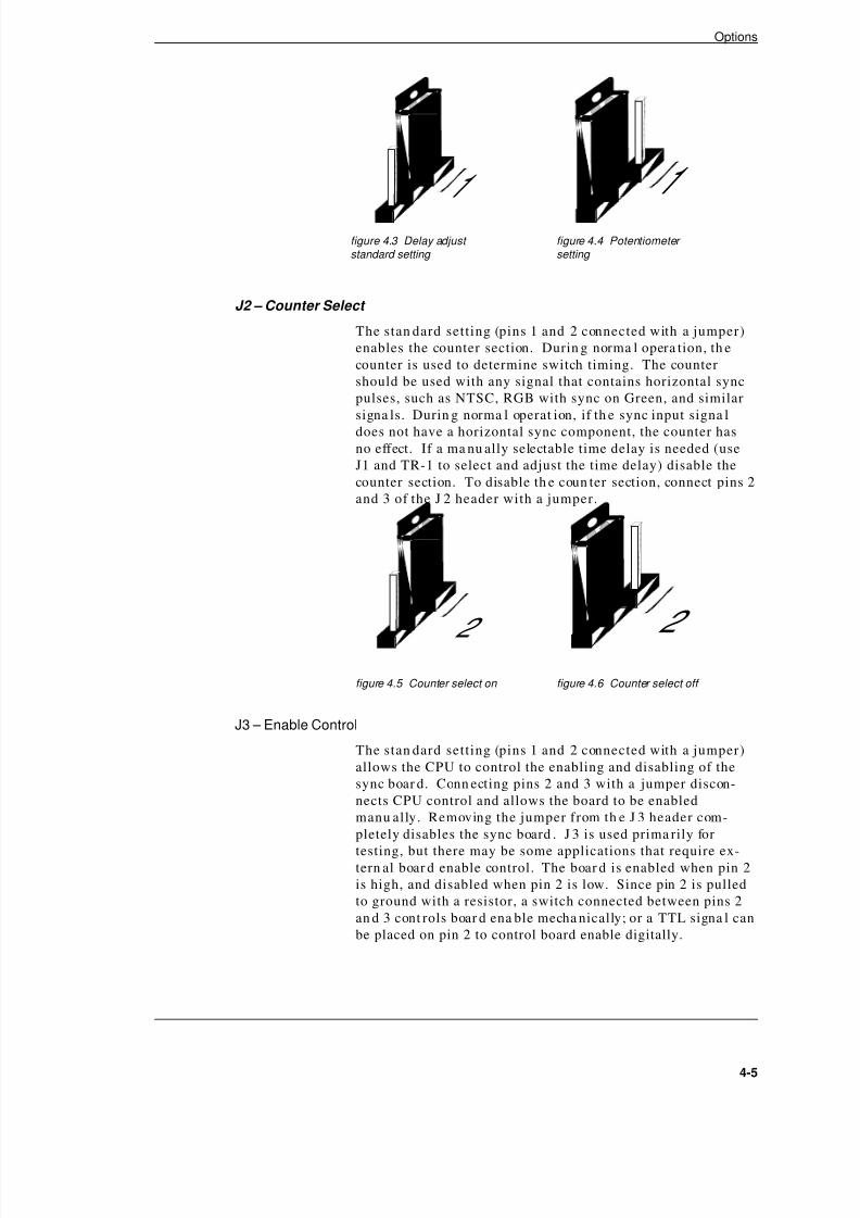
8/3/2019 amx 1Y.InstructionManual
http://slidepdf.com/reader/full/amx-1yinstructionmanual 42/82
J2 – Counter Select
The stan dard setting (pins 1 and 2 connected with a jumper)
enables the counter section. Durin g norma l opera tion, th e
counter is used to determine switch timing. The counter
should be used with any signal that contains horizontal sync
pulses, such as NTSC, RGB with sync on Green, and similar
signa ls. Durin g norma l operat ion, if th e sync input signa l
does not have a horizontal sync component, the counter has
no effect. If a ma nu ally selectable time delay is needed (use
J1 and TR-1 to select and adjust the time delay) disable the
counter section. To disable th e coun ter section, connect pins 2
and 3 of the J 2 header with a jumper.
J3 – Enable Control
The stan dard setting (pins 1 and 2 connected with a jumper)
allows the CPU to control the enabling and disabling of the
sync boar d. Conn ecting pins 2 and 3 with a jumper discon-
nects CPU control and allows the board to be enabled
manu ally. Removing the jumper from th e J 3 header com-
pletely disables the sync board . J 3 is used prima rily for
testing, but there may be some applications that require ex-tern al boar d enable control. The boar d is enabled when pin 2
is high, and disabled when pin 2 is low. Since pin 2 is pulled
to ground with a resistor, a switch connected between pins 2
an d 3 cont rols boar d ena ble mecha nically; or a TTL signa l can
be placed on pin 2 to control board enable digitally.
4-5
Options
2
figure 4.5 Counter select on
2
figure 4.6 Counter select off
1
figure 4.3 Delay adjust standard setting
1
figure 4.4 Potentiometer setting

8/3/2019 amx 1Y.InstructionManual
http://slidepdf.com/reader/full/amx-1yinstructionmanual 43/82
4.1.3 Installing a Sync Board
Each enclosure in a distribution matrix can contain one sync
boar d. If you originally ordered sync boar ds, they ar e already
insta lled in your enclosur es.
To install a sync board:
Warning: To avoid ES D (Electrosta tic Discha rge) dama ge tosensitive components, make sure you are properly
grounded before handling any boards.
1. Unplug the power cord from th e rear of the enclosure.
2. Remove the faceplate from th e third expansion slot down
from t he t op of the enclosure.
3. Line up the board with the board guides on the inner side
walls of th e slot. Make sur e the conn ectors ar e on th e
upper side of the board.
4. Carefully push the board all the way in, until it snaps into
place. If th e boar d resists going in, the pins are n ot lined
up with th e receptor. Realign th e pins and try a gain.
5. Attach the fitt ed faceplat e over the sync boar d connectors.
6. Once you ha ve added sync boards to all the enclosures
that need them, apply power to all enclosures in the
distribution matrix.
4.1.4 Enabling a Sync Board
After installing your sync board, enable it by turning on bit 4
of th e configurat ion word. For more inform ation on editing
th e configur at ion word, see section 2.6, “Chan ging the Con-
figura tion Word.” You can a lso ena ble your sync board by
attaching a TTL line to pin 2 of the J3 header (digitally en-
ables an d disables th e board) or conn ecting a switch between
pins 2 an d 3 t o manua lly enable and disable the board.
4.2 Pluggable Connectors on Audio Boards
Pluggable connectors ar e sta nda rd for your 1YDM audio
boar ds With th e pluggable connectors, each group of four in-
puts (or outputs) uses a single connector that plugs into a
fixed connector on the board.
4-6
Chapter 4
figure 4.7 CPU control enabled
figure 4.8 Manual control enabled

8/3/2019 amx 1Y.InstructionManual
http://slidepdf.com/reader/full/amx-1yinstructionmanual 44/82
Pluggable connectors allow connections to be wired into half
of the t otal conn ector, awa y from t he board, a nd plugged in
later. They also allow aud io input s an d output s to be quickly
disconnected from t he board if rapid board or connection re-
placement is desired.
Pluggable connectors are installed on audio boards at the fac-
tory when th ey are ordered.
4.3 Front Panel
The front pan el is an optional contr ol pan el on t he front of an
enclosure. You have thr ee front pa nel options:
Local X/Y Control Panel (three available
configurations: 8x8, 12x4, or 16x16)
Remote X/Y Control Unit
Blank Front Panel
4.3.1 Local X/Y Control Panel
The Local X/Y Cont rol Pan el is a contr ol panel on t he front of
an enclosure. The 1YDM Local X/Y Contr ol Panel int erfaces
thr ough the LEDs above th e buttons. Different LE D combi-
nations have different meanings.
Using a Local X/Y Control Panel on at least one of the enclo-
sures in your distribution matrix (usually the master
enclosure) has several advantages. One advanta ge is th e abil-
ity to use it for t roubleshooting. By using th e Local X/Y
Control Panel, you can segregate the distribution matrix from
the rest of your system for tr oubleshooting.
4-7
Options
figure 4.9 Standard Local X/Y Control Panel (top), 16x16 Local X/Y Control Panel (bottom).Your enclosure(s) may differ from those shown above.
AutoPatchTM
1YDM Series
CANCEL TAKE
O U TP U TI NP U TM A TR I X
PRESET CHANGE
Power ON

8/3/2019 amx 1Y.InstructionManual
http://slidepdf.com/reader/full/amx-1yinstructionmanual 45/82
The Local X/Y Control Panel can also be used as redundant
cont rol. If your m ain contr oller fails, you can st ill cont rol the
distribution ma tr ix through th e Local X/Y Cont rol Pan el.
The Local X/Y Cont rol Pan el is easy to us e; it is designed with
the end u ser in mind. The keys are designed to make t heir
functions ea sy to recognize. For example, all the input keys
are white an d all the output keys are blue.
If you originally ordered a Local X/Y Control Panel, it is al-
ready insta lled on your m ast er enclosure. Other wise, you
mu st remove the enclosure lid to insta ll a Local X/Y Contr ol
Panel.
To remove the enclosure lid:
Warning: To avoid ES D (Electrosta tic Discha rge) dama ge to
sensitive components, make sure you are properly
grounded before opening a n enclosure.
1. Disconnect th e power from your distribut ion mat rix.
2. Remove the two machine screws furt hest toward the back
on each side of the enclosure (a total of four screws are
removed). See figure 4.10.
3. Remove the flathead screw from the center of the
enclosure lid.
4. Slide the l id toward t he front of the enclosure an d l ift th e
back of the lid u p. The lid should slide out of its grooves.
To install a Local X/Y Control Panel after removing the enclosure lid:
Warning: To avoid ES D (Electrosta tic Discha rge) dama ge to
sensitive components, make sure you are properly
grounded before handling the internal workings of an enclosure.
1. Remove the blank front panel by removing the two screws
fur th est forwar d on each side of the enclosur e (a total of
four screws) an d tilting the pan el forward. See figure
4.11. You will need a .25 inch open end wr ench to remove
the nuts from the screws inside the enclosure.
4-8
Chapter 4
AutoPatchTM
1YDM Series
CANCEL TAKE
O U T P U TI N P U TM A T R I X
PRESET CHANGE
Power ON
figure 4.10 Removing a 1YDM enclosure lid.

8/3/2019 amx 1Y.InstructionManual
http://slidepdf.com/reader/full/amx-1yinstructionmanual 46/82
2. Align t he lip on t he bottom of the Local X/Y Control Panel
with th e groove along the inside bottom of th e enclosur e
and ti lt the panel into place.
3. Fasten the Local X/Y Control Panel in place with the
screws and nu ts th at h eld the blank front pa nel.
4. Attach the ribbon cable (ha s a red wire along one side) to
th e port inside the enclosur e. The port is directly above
the rear main board. The red wire on th e ribbon cableshould face th e closest en closur e wall a t th e enclosur e
port, and should face up at the panel connection.
5. Attach th e 5V power cable to the Local X/Y Contr ol Pa nel
instead of the blank front panel (the little bumps on the
cable’s conn ector should face up). The oth er en d of th is
cable is already conn ected.
6. Replace the enclosure l id and the screws. Make sure the
flat head screw goes in t he center of th e lid.
7. Reconnect power to your distribution ma trix.
4.3.2 Remote X/Y Control Unit
A Remote X/Y Cont rol Unit is an X/Y Cont rol Pan el tha t is
not in the sam e locat ion as your distribution mat rix. A Re-
mote X/Y Control Unit is mounted on an enclosure that
contains minimal component s.
A Remote X/Y Cont rol Unit offers all th e a dvant ages of a Lo-
cal X/Y Contr ol Panel with th e add ed benefit of distan ce.
With the Remote X/Y Control Unit, you can control your sys-
tem or troubleshoot without being in the heart of your system.
Using RS-232 link cable, your remote can be up to 100 feet
(32.8 m) from your distribution ma tr ix. Using RS-422 link ca-
ble, your remote can be up to .25 mile (400 m) from your
distribution matrix.
Insta lling a Remote X/Y Contr ol Unit is just like linking en-
closur es in a multi-enclosur e distribut ion m atr ix.
4-9
Options
AutoPatchTM
1YDM Series
Power ON
figure 4.11 Removing a blank front panel

8/3/2019 amx 1Y.InstructionManual
http://slidepdf.com/reader/full/amx-1yinstructionmanual 47/82
To install a Remote X/Y Control Unit:
Warning: To avoid ES D (Electrosta tic Discha rge) dama ge to
sensitive components, make sure you are properly
grounded before handling any boards.
1. Detach power from all th e enclosur es in the distribution
matrix.
2. Link the remote front panel to the distribution matr ix.See section 1.3, “Linking Enclosures,” for more
informa tion on linking enclosur es.
3. Ensur e that th e voltage selectors on the remote and all
other enclosures in the distribution matrix are in the
corr ect position.
4. Attach power to each enclosure in th e distribution ma trix,
including th e Remote X/Y Cont rol Unit. The distr ibution
matr ix goes th rough its star tup sequence.
4.3.3 Blank Front Panel
A blank front panel is an AutoPatch front panel with one indi-cator LED and no control keys. The blank front pa nel is the
standa rd pan el attached to the front of an enclosure. The
only indicator on th e blank front pan el is the gr een on/off in-
dicat or LED.
The main advantage of a blank front panel is the inability of
anyone in direct contact with the distribution matrix to alter
any of its settings.
Although a Local X/Y Control Panel is recommended for trou-
bleshooting and redun dan t cont rol, it is p ossible to control
your 1YDM without an X/Y Control Panel. Several meth ods
for cont rolling your 1YDM th rough t he ser ial ports a re a vail-able. For more informat ion on using an externa l controller
an d t he t ypes of externa l cont rollers a vailable, refer to section
4.4, “Using Extern al Contr ollers.”
4-10
Chapter 4
AutoPatchTM
1YDM Series
Power ON
figure 4.12 Blank Front Panel

8/3/2019 amx 1Y.InstructionManual
http://slidepdf.com/reader/full/amx-1yinstructionmanual 48/82
4.4 Using External Controllers
Several options for operating your distribution matrix are
available, including using a contr ol panel, an externa l cont rol-
ler, or dr y contacts. An external cont roller is an y device th at
can send and receive information from the distribution matrix
via t he serial port (such as a PC). Dry cont acts provide physi-
cal switches for recalling presets. Any externa l cont roller
other than Single Bus Controllers (SBC) and dry contacts can
program presets.
The 1YDM may be contr olled by an externa l device that can
send ASCII code via t he ser ial port; any such device is consid-
ered a n exter na l controller. Some specific types of externa l
controllers ar e SBCs, Remote X/Y Cont rol Unit, PC or Macin-
tosh computer, an d third par ty control devices. Extern al
controllers must be able to send Basic Control Structure
(BCS) comma nds. A distribut ion m at rix can support only one
externa l cont roller, alth ough it can h ave a combinat ion of an
external controller and dry contacts.
SBCs come in a choice of two control methods; one allows you
to control the input routed to a particular output device, the
oth er a llows you t o recall presets. Neither type of SBC allows
you to store presets.
A Remote X/Y Cont rol Unit may be placed up to 100 feet (us-
ing RS-232 communications), or 1000 feet (using RS-422
commun icat ions), from th e distribut ion m atr ix. Remote X/Y
Control Units attach to the serial port on the back of the mas-
ter enclosure in your distribution matrix and behave the same
as a Local X/Y Control Panel.
A PC or Ma cintosh compu ter can a lso be used t o cont rol yourdistribution ma trix with a ny program tha t can tr ansmit at
9600 BAUD an d send BCS comman ds. AutoPatch has several
control programs available: YRoute, WinRoute, AutoRout e
Event Scheduler, an d ScanPa tch.
Each type of remote controller is specialized for different
types of applications, but they all allow you to access your dis-
tribution matrix without being in the heart of your system.
4.4.1 Attaching an External Controller
External controllers can be attached to either serial port 1 or
serial port 2 of an enclosure in your m atr ix; serial port 1 of
your m aster enclosure is preferred. Serial port 2 does not
echo commands and is not recommended for use with external
controllers.
The ser ial ports can receive th ree t ypes of commun icat ion,
RS-232, RS-422, and RS-485. RS-232 and RS-422 are t he
stan dar d commu nication pr otocols used. RS-485 is genera lly
used with SBCs. Un less specifically ordered a s an other pr oto-
col, the su pplied seria l cable(s) is set for RS-232. The ser ial
port jumper s ar e also set for t he t ype of commun icat ion sp eci-
4-11
Options
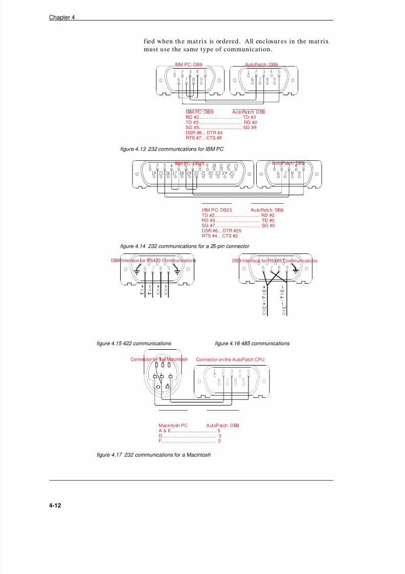
8/3/2019 amx 1Y.InstructionManual
http://slidepdf.com/reader/full/amx-1yinstructionmanual 49/82
fied when th e mat rix is ordered. All enclosur es in the mat rix
must use the same type of communication.
4-12
Chapter 4
figure 4.13 232 communications for IBM PC
IBM PC: DB9 AutoPatch: DB9
IBM PC : DB 9 Au to Pa tc h: D B9RD #2................................. TD #3TD #3.................................. RD #2SG #5................................. SG #5DSR #6... DTR #4RTS #7... CTS #8
figure 4.14 232 communications for a 25-pin connector
IBM PC: DB25 AutoPatch: DB9
IBM P C: DB2 5 Au to Pa tc h: DB9TD #2................................... RD #2RD #3................................... TD #3SG #7................................... SG #5DSR #6... DTR #20RTS #4... CTS #5
figure 4.15 422 communications
DB9 Interface for RS422 Communications
figure 4.16 485 communications
DB9 Interface for RS485 Communications
figure 4.17 232 communications for a Macintosh
Connector on the Macintosh Connector on the AutoPatch CPU
Macintosh PC AutoPatch: DB9A & E................................... 5D.......................................... 3F.......................................... 2
8/3/2019 amx 1Y.InstructionManual
http://slidepdf.com/reader/full/amx-1yinstructionmanual 50/82
To attach an external controller to the distribution matrix:
Connect a serial cable between the external controller and one
of the ser ial ports on a n en closure (preferably serial port 1 of
the m aster enclosure). Transmit, receive, and ground mu st be
run from the external controller to the distribution matrix.
Since no handshaking is provided by the distribution matrix,
make the serial cable connector pinouts as seen in figures
4.13 - 4.17. If multiple enclosur es ar e linked, connect t he ex-ternal controller to the master enclosure using serial port 1.
Daisy-chain t he r est of the enclosur es as shown in figure 1.2,
in section 1.3, “Linking Enclosures.”
Before attaching an external controller, the distribution ma-
trix’s configur at ion word n eeds to be updat ed. Detailed
information about the configuration word is in section 2.6,
“Chan ging th e Configura tion Word.”
If you are using SBCs with the distribution matrix, you must
allow it to poll all th e SBCs. The CPU polls the SBCs for a ny
chan ge requests. If the CPU finds a switch, it is ma de imme-
diately.
After the serial connections are made and the distribution
matrix is powered up, the external controller screen displays
the version number, the slots of the enclosure that contain I/O
boar ds, and sp ecific informa tion about th ose boar ds. If the
message does not appear on the screen, the serial port the ex-
ternal controller is attached to may be set to poll SBCs.
Change to Program mode and check the setting of the respec-
tive serial port. See figure 2.3, in section 2.6.10, “Setting t he
Configur at ion Word,” for furt her expla na tion. Also verify
commun icat ions protocol by checking t he jum per on the CPU
board.
Your distribution matrix should now be ready to be operated
via the serial port.
4.5 Using a Dumb Terminal
A dumb terminal is a non-programmable input device that
sends ASCII cha ra cters to the ma ster enclosur e. An example
of a dumb terminal is a keyboard attached to the serial port of
a 1YDM mast er enclosure. A dumb term inal could also be a
keyboard and monitor, where the keyboard sends the ASCII
character and the monitor displays the echo.
When you are using a dumb terminal, the capitalized ASCII
char acter must be sent to the master enclosure. The terminal
must tra nsmit at 9600 BAUD with 8 dat a bits, 1 stop bit , and
no par ity.
4-13
Options

8/3/2019 amx 1Y.InstructionManual
http://slidepdf.com/reader/full/amx-1yinstructionmanual 51/82
4.6 Single Bus Controllers (SBC)
A Single Bus Controller (SBC) is similar to a specialized ex-
tern al controller. SBCs are not mount ed on th e enclosur e, but
they do send and receive communications to and from the en-
closure. SBCs ar e available in two versions of three models.
Ea ch model ha s a different faceplate. Ea ch faceplate h olds
different keys, so the m ethod of selecting a n input or preset
differs from model to model. The t wo version t ypes define th e
operations you can perform with your SBC(s).
A distribution matrix can intermix SBC models and versions;
however, two SBCs connected to th e sa me en closur e cann ot
have the same identification number.
This section discusses the following:
Versions
Models
Installation
Polling SBCs
4.6.1 Versions
N o t e : There ar e no ph ysical indicators for different iating
between the C version and the P version of SBCs; but,
the versions are n ot interchan geable. Th e versions
can be mixed if properly connected.
The C version of an SBC is tied t o a specific outp ut device and
cont rols what input is rout ed to the device. The output device
th at th e SBC is tied t o is specified by the d ipswitch sett ing on
th e SBCs logic board (the board directly behind the faceplat e).
This SBC version uses the output connector number (in rela-
tion to th e enclosur e th e output is on) as its identification
n u m b e r .
4-14
Chapter 4
f igure 4.18 3-key SBC model f igure 4.19 12-key SBC model f igure 4.20 16-key SBC model

8/3/2019 amx 1Y.InstructionManual
http://slidepdf.com/reader/full/amx-1yinstructionmanual 52/82
The P version of an SBC is used to recall presets; however,
the 16-key model can only recall presets #1-16. The P version
of the SBC is not tied to a particular input or output, but it
still needs an identificat ion n umber for polling. This SBC
version’s ident ificat ion n um ber is user defined.
4.6.2 Models
Each SBC model gives you a different degree of flexibility, de-
pending on your system. The thr ee SBC models are a s
follows: 3-key, 12-key, an d 16-key.
4.6.2.1 The 3-Key
The 3-key SBC is designed for small systems with only a few
input s and/or presets. The th ree keys on th is model are: <+>,
<->, an d <*10>. Pr essing <+> increases the inpu t chan nel se-
lection or preset selection by one, pressing <-> decreases it by
one, a nd pressing <*10> increases or decreases it by 10 in
conjun ction wit h <+> or <->. The 3-key model works well for
small systems because of the interval associated with the
keys on t he keypad. You can quickly cha nge th e selection inthis model by holding down <+> or <-> and scrolling to the de-
sired num ber. The num ber choices are circularly sequent ial,
so if you scroll past the number you want, it comes around
again without reversing scroll direction.
4.6.2.2 The 12-Key
The 12-key SBC model is designed for system s with man y in-
put s. This model offers two meth ods for cha nging the inpu t
channel selection or preset selection: direct access and se-
quential . The num bered keys on this keypad implement
direct access; <+> and <-> allow you to scroll to the number
you wa nt to select. The scrolling is circular ly sequential, so if you scroll past the number you want, you will return to it
without reversing scroll direction.
To make a selection using direct access, use the numbered
keys on t he keypad. All numbers must be entered as double
digits. Single digit ent ries and entr ies higher tha n t he high-
est valid num ber ar e ignored. An entr y of 00 selects your last
valid entry. To can cel an incorr ect single digit en tr y, press
<+> or <->; the display returns to your last valid entry.
4.6.2.3 The 16-Key
The 16-key model is designed for systems with 16 or less in-put s or presets. The faceplate of th is model contains 16 keys
that are n umbered from 1 t o 16. There are n o <+> or <-> keys
on t his model. The 16-key SBC selects inpu ts or recalls pre-
sets with the touch of one key. However, since the only keys
on the keypad are numbered 1-16, you can only select an in-
put or preset within that range.
4-15
Options

8/3/2019 amx 1Y.InstructionManual
http://slidepdf.com/reader/full/amx-1yinstructionmanual 53/82
4.6.3 Installation
To install an SBC, prepare each enclosure in the distribution
ma trix to receive a chain of SBCs. Make su re all your wiring
is done correctly before mounting your SBC(s).
To prepare the enclosures:
Warning: To avoid ESD (Electrostatic Discha rge) dama ge
to sensitive components, make sure you are prop-
erly grounded before handling any boards.
1. Set the enclosur e’s polling range equal to th e highest SBC
identification number, see section 2.6.7, “Single Bus
Controller (SBC) Polling Limit.”
2. Set the enclosure’s serial port jumpers (J 1 and J 2 on th e
CPU board) for RS-422 communications, see figure 4.21.
N o t e : The communication protocol is RS-485; however, the
jum per set tings for RS-422 an d RS-485 are identical.
3. Wire th e enclosur e’s serial port s for RS-485 standa rds, seefigure 4.22.
All SBCs that are u sed with the sam e enclosure mu st be
linked together in daisy cha in fashion. The order of SBC
identification numbers in the daisy chain does not matter.
4-16
Chapter 4
figure 4.21 422 communications jumper setting
figure 4.22 RS-485 communications pinout

8/3/2019 amx 1Y.InstructionManual
http://slidepdf.com/reader/full/amx-1yinstructionmanual 54/82
To daisy chain SBCs:
1. Use P1 and P2. (They are two of three blue connectors on
th e back side of th e logic boar d.) P1 is t he exit conn ector
an d P2 is the ent ry connector. See figure 4.23.
2. Conn ect a low capacita nce cable for EIA RS-485 standa rd
(2 pair twisted 24 gauge/str an ded condu ctors (7x32). e.g.,
Belden #1419A= NE C:CM PCC F T 1) from th e + on th e
exit connector of the SBC t o the + on t he en try connector
of the next SBC in the chain. Do the same for - and GND.
3. Use figure 4.23 as a guide for linking all SBCs, except the
first and final SBCs in the chain.
4. The final SBC in the chain must be terminated with a 120
ohm resistor as shown in figure 4.24.
4-17
Options
figure 4.23 Beginning connections in an SBC chain
figure 4.24 Final SBC in chain

8/3/2019 amx 1Y.InstructionManual
http://slidepdf.com/reader/full/amx-1yinstructionmanual 55/82
4.6.3.1 Connecting Power
The power conn ector is t he blue connector on th e back of the
logic boar d tha t ha s no oth er blue connectors a round it. See
figur e 4.25. The r ecomm ended p ower for SBCs is 7-12V DC,
but r egulated 5V DC may also be used. The power regulat ion
jum per is set to accept 7-12V DC. Be sur e to provide power
sufficient for 160 milliam ps per SBC . A 9V wall plug-
mount ed power tr an sform er is suggested. Call your localdealer for inquiry.
To connect unregulated DC power to an SBC, unscrew the top
and bottom screws on the blue power connector and insert the
wires as sh own in figur e 4.25. To use regulated 5V DC,
switch the power regulation jumper before attaching power to
th e SBC (see figure 4.26). Once the jumper h as been set for
regulated power, unscrew the middle and bottom screws on
the power connector and insert the wire.
The final step before using an SBC is mounting it in its final
location. Make su re a ll the wiring is done corr ectly before
mounting an SBC in its permanent location.
4-18
Chapter 4
figure 4.25 Connecting power for unregulated power
P 9 figure 4.26 P9 jumper set for unregulated power

8/3/2019 amx 1Y.InstructionManual
http://slidepdf.com/reader/full/amx-1yinstructionmanual 56/82
SBCs ar e designed to fit in a cont ainer th e size of a two-gang
electrical box (4″ x4″ x2+″ ). When mount ing an SBC in a gang
box, it may be necessary to tilt the SBC at a slight angle to
get the circuit board past the tabs.
The following electrical box has been verified by AutoPatch to
properly fit AutoPat ch SBCs:
Manufactur er: Bowers
D es cr i pt i on : T w o G a n g b ox
Model #: 132W-½ (the ½ is the diameter of the knock-
out hole and can vary per installers requirements)
D im e n sion s : 4″ squar e 2 1/8 (30/3 Cu . In. capacity)
Four mount ing holes, indicated by blue circles, are provided
on every SBC control panel. The holes are n ot tapped un less
tapp ing is specified when th e SBC is ordered. Bezels can also
be requested for SBC units.
4.6.4 Polling Single Bus Controllers
Setting t he polling limit in th e configur at ion word of the m as-
ter en closure au tomat ically begins the p olling process. If the
polling limit is set before you a tta ch SBCs, th e distribut ion
mat rix is not affected. However, you can not poll without set-
ting t he SBC polling limit.
The SBC polling limit informs t he CP U of how many S BCs to
look for du ring polling. The 8th th rough 12th bits of th e con-
figurat ion word control the polling limit. The CP U polls from
1 to what ever limit is set. For more informa tion about chan g-
4-19
Options
figure 4.27 Mount an SBC in a two-gang box
Keypad
Logic Board
Optional Bezel
Two-GangElectrical Box

8/3/2019 amx 1Y.InstructionManual
http://slidepdf.com/reader/full/amx-1yinstructionmanual 57/82
ing sett ings in t he configurat ion word, see s ection 2.6,
“Chan ging the Configur at ion Word.” Use t he following chart
to set th e bits for t he polling limit. A bit set to 1 is on, a bit
set to 0 is off.
4-20
Chapter 4
B it S e ttin g P oll Lim it
8t h 9 t h 1 0 th 1 1 t h 12 t h
0 0 0 0 0 1
1 0 0 0 0 2
0 1 0 0 0 3
1 1 0 0 0 4
0 0 1 0 0 5
1 0 1 0 0 6
0 1 1 0 0 7
1 1 1 0 0 8
0 0 0 1 0 9
1 0 0 1 0 10
0 1 0 1 0 11
1 1 0 1 0 12
0 0 1 1 0 13
1 0 1 1 0 14
0 1 1 1 0 15
1 1 1 1 0 16
0 0 0 0 1 17
1 0 0 0 1 18
0 1 0 0 1 19
1 1 0 0 1 20
0 0 1 0 1 21
1 0 1 0 1 22
0 1 1 0 1 23
1 1 1 0 1 24
0 0 0 1 1 25
1 0 0 1 1 26
0 1 0 1 1 27
1 1 0 1 1 28
0 0 1 1 1 29
1 0 1 1 1 30
0 1 1 1 1 31
1 1 1 1 1 32

8/3/2019 amx 1Y.InstructionManual
http://slidepdf.com/reader/full/amx-1yinstructionmanual 58/82
Single enclosur e distribut ion mat rices a nd multi-enclosure
mat rices poll SBCs in the same ma nn er. There is no differ-
ence in the procedure for polling in either distribution matrix
system.
4.7 Software
Contr ol softwar e allows a PC t o control a distr ibution m atr ixthr ough the serial ports. AutoPatch offers cont rol softwar e
that executes switches man ually and aut omatically. The
manual execution software implements commands when they
are enter ed. The aut omatic execut ion software implement s
commands at the times they are scheduled to be executed.
The manual execution software packages are YRoute and
WinRoute. The au tomatic execution softwar e packages are
AutoRoute Event Scheduler and ScanPatch.
4.7.1 YRoute
YRoute is a DOS-based software package that simulates all
configur at ion opera tions, except checking the sta tus of an in-put or output. Operations ar e implemented by entering the
comman ds (from th e top of th e screen) at t he option? prompt.
Before using YRoute, familiarize yourself with the operation
of your distribution ma trix from the mast er en closure Local
X/Y Cont rol Pa nel. YRout e can only be run on a P C tha t uses
RS-232 communications.
N o t e : Using YRoute requires an RS-232 cable with the
ha ndsh aking pins sh ort ed. See figur es 4.13 - 4.17 in
section 4.4.1, “Attaching a n Extern al Cont roller.”
4.7.2 WinRoute
WinRoute is a Windows based software package with a cus-
tomizable gra phical interface. Ea ch inpu t an d each output is
represented by an icon, and connections are represented by
lines between input s and outpu ts. The icons can be placed in
an y patter n you desire inside th e WinRoute window. For ex-
ample, t he icons can be placed to m imic the ph ysical locat ions
of devices around your office.
N o t e : WinRoute can only be run on a PC that uses RS-232
communications and runs Windows 3.1 or higher, in-
cluding Windows 95.
4.7.3 AutoRoute Event Scheduler
AutoRout e Event Scheduler is a DOS-based cont rol progra m
tha t schedules events for ma trix processing. Comma nd lines
must be entered in the string file, which is scheduled in the
event file. The event file is processed by AutoRout e Event
Scheduler. Pr ocessing the event file allows th e softwar e to
cha nged th e distribut ion mat rix configura tion according to
user defined parameters, including command and event tim-
ing. AutoRoute E vent Scheduler can h an dle up to 100 events
4-21
Options

8/3/2019 amx 1Y.InstructionManual
http://slidepdf.com/reader/full/amx-1yinstructionmanual 59/82
an d 100 strings. The str ings can r ecur in intervals of one sec-
ond to one year.
N o t e : AutoRoute Event Scheduler can only be run on a PC
tha t uses RS-232 commu nications; see figures 4.13 -
4.17 in section 4.4.1, “Attaching a n Extern al Contr ol-
ler.”
4.7.4 ScanPatch
ScanPa tch is a DOS-based contr ol program tha t cycles I/O
configurations. Each output has a set of assigned inputs t hat
ar e cycled th rough it. Ea ch Scan Pa tch session can h an dle up
to 128 outp uts, with a set of input s for each outpu t. Ea ch set
can conta in no more th an 40 inputs. The length of a Scan-
Patch session can be predefined or you can let it run until you
need or want to terminate i t .
N o t e : ScanPatch can only be run on a PC that uses RS-232
communications; see figures 4.13 - 4.17 in section
4.4.1, “Attaching a n Extern al Contr oller.”
4-22
Chapter 4

8/3/2019 amx 1Y.InstructionManual
http://slidepdf.com/reader/full/amx-1yinstructionmanual 60/82

8/3/2019 amx 1Y.InstructionManual
http://slidepdf.com/reader/full/amx-1yinstructionmanual 61/82
5.1.1 Change Key
<Chan ge> is u sed for initiat ing switches in th e I/O configura-
tion of a distribut ion m atr ix. See section 2.1, “Making a
Switch,” for inst ru ctions on using t he Ch an ge key.
5.1.2 Preset Key
A preset is a “picture” of an input/output (I/O) configuration.
When you define a preset, you assign a preset number to the
current I/O configurat ion an d it is stored in th e CPU. That
I/O configuration, in its entirety, can then be restored at any
time by recalling i ts preset n umber. The preset key is used
for defining an d r ecalling presets. See section 2.5, “Using
Pr esets,” for instr uctions on defining a nd recalling presets.
5.1.3 Matrix Keys
When making a switch, the matrix keys are used for selectingan I/O boar d level. The ma tr ix keys ar e also used for choosing
a specific ban k of preset nu mbers when defining or recalling
presets.
5.1.4 Input Keys
The Input keys are used for selecting an input during a
switch operation and for specifying or recalling a preset
num ber. The Input k eys are a lso used for setting the adjust-
able featu res of th e distribution mat rix. Section 2.6,
5-2
Chapter 5
1 2 3 4 5 6 7 8 9 1 0 11 12 13 14 15 161 2 3 4
AutoPatchTM
1YDM Series
CANCEL T A K E
OU T P U TI NP U TM A TR I X
PRESET CHANGE
Power ON
Figure 5.1 Standard 1YDM Local X/Y Control Panel (top), 16x16 1YDM Local X/Y Control Panel (bottom).Your matrix’s front panel may differ from those pictured above.

8/3/2019 amx 1Y.InstructionManual
http://slidepdf.com/reader/full/amx-1yinstructionmanual 62/82
“Chan ging the Configur ation Word” discusses th e adjust able
features these keys can access. When setting the a djustable
features, keys are referred to as bits.
5.1.5 Output Keys
The Output keys are used for selecting an output during a
change operation and for specifying a preset number when de-
fining or r ecalling presets. Outpu t keys ar e also used for
setting the adjustable features of the distribution matrix.
Section 2.6, “Changing the Configuration Word” discusses the
adjustable featur es these keys can access. When setting the
adjustable features, keys are referred to as bits.
5.1.6 Cancel Key
<Cancel> terminates unfinished operations and disconnects
inputs and outputs.
5.1.7 Take Key
<Take> execut es valid operat ions. Always be su re t o com-
pletely specify an opera tion. If <Take> is pr essed before an
operation is completely specified, it has the same effect as
pressing <Cancel>.
5.2 Rear of an Enclosure
The r ear of an enclosure is wher e all th e physical conn ections
are m ade. It cont ains a udio and video I/O connectors, expan -
sion slots, the CPU , and t he rear main.
5.2.1 Audio and Video I/O Connectors
The au dio and video input and output connectors are atta ched
to audio an d video I/O board s within th e enclosure. The
number and type of connectors depends on the number and
type of I/O boar ds. The input an d output conn ectors on the
board are numbered right to left on the rear of the enclosure.
Looking at the rear of the enclosure, the inputs are on the
right in white and t he outputs a re on the left in black.
5-3
The Enclosure and Its Parts
figure 5.1 Rear view of a 1YDM enclosure 3 rack unit and 4 rack unit enclosures not shown.

8/3/2019 amx 1Y.InstructionManual
http://slidepdf.com/reader/full/amx-1yinstructionmanual 63/82
5.2.2 Expansion Slots
The expansion slots are above the CPU on the rear of the en-
closure an d a llow the a ddition of a vertical interval sync
expansion board in systems that were originally ordered with-
out one. One slot is used by the CPU board a nd one can be
used for t he sync boar d. An additiona l expan sion slot is avail-
able for a ny future upgrades th at may occur. For more
information about the Vertical Interval Sync Expansion
boar d, see section 4.1, “Vert ical In terval Sync Expan sion
Boards.”
5.2.3 CPU
The CPU is usua lly locat ed in th e top expansion slot. It ha s
two DB-9 serial ports for linking to other enclosures, r eceiving
communication from Single Bus Controllers (SBC), and com-
municating with other serial devices, such as a PC.
5.2.4 Rear Main
The rear main contains the voltage selector, the fuse, and the
power connector.
The voltage selector can be set at 110V or 220V. Make su re
the voltage selector of each enclosure is on the correct voltage
setting before app lying power.
Each enclosure in the distribution matrix contains a 1 amp
fuse. To release t he fuse, tur n t he fuse covering counterclock-
wise.
Power must be applied to all enclosures in the distribution
ma trix. Since th ere is no power switch on th e enclosures, at-
taching the power cord to an outlet turns the distribution
ma trix on. It ma y be helpful to plug each enclosure into a
power strip an d th en plug the power strip into an outlet .
5.3 I/O Boards
Each 2 rack unit enclosure can contain up to four I/O boards,
3 rack unit enclosures can contain up to six boards, and 4
rack unit enclosures can contain up to eight boards. An enclo-
sur e’s boards can be an y combinat ion of au dio and video.
Each board ha s two adjustable features, input impedance and
input gain control. Adjust t he input impedance using the im-
pedance jumpers.
5-4
Chapter 5
figure 5.2 Rear main

8/3/2019 amx 1Y.InstructionManual
http://slidepdf.com/reader/full/amx-1yinstructionmanual 64/82
5.3.1 Impedance Jumpers
1YDM video boar ds h ave a two-pin jumper th at selects a low
or h igh input impedance. Each input signal ha s i ts own
jum per locat ed directly behind th e signal connector. When
the jumper is capped, impedance is 75 ohms . If th e jump er is
not capped, inpu t impedan ce is 24K ohm s. If your board does
not have a jumper, the jumper was replaced by a 0 Oh m r esis-
tor and impedance cannot be changed.
5.3.2 Gain Control
Gain control on audio and video output signals is standard.
AutoPatch a lso offers a udio and video board s with input gain
control. At the factory, input s and outpu ts ar e set to an over-
all gain of 1 (unity gain).
An extender board and gain control tool are included with the
1YDM. Ea ch signal’s gain contr ol is directly behind t he sig-
na l connector a nd is labeled TR#.
5-5
The Enclosure and Its Parts

8/3/2019 amx 1Y.InstructionManual
http://slidepdf.com/reader/full/amx-1yinstructionmanual 65/82
Chapter 6—ApplicationsThe 1YDM provides several m ethods to expand system capa-
bilities an d overa ll flexibility. This chap ter explores two of
these methods by explaining them and going through an ex-
ample of each. This chapter also explores t he possibility of
combining t he m ethods an d pr ovides examples of th em com-
bined.
This chapt er covers:
G Para lleling Input s
G Loop Back
G Fur ther Examples Combining Pa rallel Inputs and Loop
Back
6.1 Paralleling Inputs
Ea ch input /outp ut (I/O) boar d in a 1YDM enclosur e is its own
switching environment, so the inputs of one board cannot be
switched to the out put s of an other board. However, para llel-
ing inputs allows any input to switch to any output in th e
distribution ma trix that h as an identical signal path. By par-
alleling inputs, the set of configuration possibilities for the
distribution m atr ix expands to include: 4x12, 8x12, 8x16
(mono audio), 12x8, 8x32 (using 8x16 boards only), and 16x32
(using 16x16 boards only).
To parallel inputs, split an input signal between two or more
input conn ectors. When splitting a video input signal, make
sure all but one of the video boards in each split set are high
impedance. Splitting a single video input signal more tha n
four times is n ot recommen ded. More tha n four signal splits
would be un contr ollable since ther e a re only four levels avail-
able on this matrix and a distribution amplifier would be
required t o boost the signal. See section 5.3.1, “Impedan ce
Jumpers,” for more information about setting the impedance.
Audio input s do not require an y impedan ce changes. If your
I/O boards do not have impedance jumpers and you are not
certain that one of them is high impedance, please contact
your authorized AutoPatch dealer.
N o t e : Set a ll but one of the video boar ds to h igh impedance.
Setting all or setting none to high impedance may pro-
vide an improper load to th e source video device a nd
is not recommen ded.

8/3/2019 amx 1Y.InstructionManual
http://slidepdf.com/reader/full/amx-1yinstructionmanual 66/82
When using para lleled inputs a nd m aking a switch to output s
beyond #1-8, the outputs must be referenced by level number
and output num ber. For example, if your distribution m atrix
has an 8x12 configuration and you want to switch Input 7 to
Output 10 (see figure 6.1), follow these steps:
1 . P r e s s < Ch a n g e >.
2. Press the level 2 Matrix key (2nd matr ix key from the
left).
3. Press the Input 7 key (7th input key from the left) .
4. Press the Output 2 key (2nd output key from the left) .
5 . P r e s s < Ta k e >.
To make th e same switch using Basic Control Structure
(BCS) comman ds, th e comma nd str ing would be a s follows:
CL2I7O2T (Change Level 2 Input 7 Out put 2 Take)
In the above example, the system will not recognize an output
identified as #10; it mu st be identified as Level 2, Outpu t 2.
To parallel inputs:
1. Set each board of a set to a different level num ber. See
section 1.5, “Definin g Levels,” for more inform at ion about
changing th e board level.
2. If a video input is being para lleled, set all but one inpu t in
the set to high impedance.
3. Split th e signal between the appropriate input connectors.
N o t e : Splitting a signal more than four times requires a
distribution am plifier.
4. Switch any paralleled input t o any available output
located on one of the boards the input is attached to.
6-2
Chapter 6
Input device #1 can beswitched to any availableoutput on the two top I/Oboards.
figure 6.1 Paralleled input on an 8x12 configuration
12345678
9101112
1
2
3
4
5
6
7
8
figure 6.2 Split the source signal to parallel inputs
SourceSourceSignal
InputsOutputs
Input Device #1

8/3/2019 amx 1Y.InstructionManual
http://slidepdf.com/reader/full/amx-1yinstructionmanual 67/82
6.1.0.1 Example of implementing parallel inputs
In this example, the signal from the source is split and con-
nected to Level 1 Input 1 a nd Level 2 Input 1. The signal
routes available to get to the output devices are
In: Level 1 Input 1
Out: Level 1 Output 1
In: Level 2 Input 1
Out: Level 2 Output 1
The source signal can be routed through one or both output
devices. Ea ch split of th e sour ce signal should be treat ed as a
separate input signal.
6.2 Loop Back
Loop back is a method that allows mid-switch processing of a
signa l. The looped signal can be mixed with other signals,
ha ve noise extr acted from it, or be converted to a different sig-
na l type, all within a n externa l processor, before r eaching its
final destina tion.
Using loop ba ck, several inpu t signa ls can be processed, in
varying order, by the sa me extern al device. You can achieve
this by attaching the signals to input connectors on the
1YDM, and at taching t he pr ocessor t o one or m ore outp ut con-
nectors an d one or more input conn ectors. The signal can
then be routed from the matrix, through the processor, and
through the ma trix again to its f inal output destination. No
new software is required for this application of your 1YDM.
Loop back is highly effective while working with signal modi-
fication devices such as line doublers, digital signal
processors, video effects, video character devices, and other
such equipment.
6-3
Applications
figure 6.3 Parallel inputs example #1
SourceS
InputsOutputs
OutputDevice #1
OutputDevice #9
S
S
Level 1
Level 2
Level 3
Level 4
8 7 6 5 4 3 2 1 12345678
From source toOutput device #1
From source toOutput device #9

8/3/2019 amx 1Y.InstructionManual
http://slidepdf.com/reader/full/amx-1yinstructionmanual 68/82
To implement loop back:
1. Attach the input signal to an input connector on the
1YDM.
2. Attach the input side of th e extern al processing device to
an output connector the source input signal can be
switched to.
3. Attach the output side of the externa l processing device toan input connector on the distribution matrix that can be
switched to the final destination.
4. Make the appropriate switches from the X/Y Contr ol
Pa nel or from an exter na l controller. Execut ing a loop
back switch is the same as executing a standard switch;
however, to get the signal to its final destination a
minimum of two inputs must be switched to a minimum
of two output s.
6.2.0.1 Example of implementing loop back:
In this example, the available signal path is
In: Level 1 Input 1
Out: Level 1 Output 1
In: Level 4 Input 1
Out: Level 4 Output 1
6-4
Chapter 6
figure 6.4 Basic Loop Back implementation
InputsOutputs
Source
Signal Processor,Output Device #1
Final Destination,Output Device #32
SourceSignal
Pure Signalfrom Source
Processed SourceSignal
Processed Signal
Input Device #1
Input Device #32
Output Device #32
Output Device #1
figure 6.5 Loop back example #1
OutputDevice #32
Video Text Generator,Output Device #1,
InputDevice #1
S1VT
S1
S2
VT
Level 1
Level 2
Level 3
Level 4
8 7 6 5 4 3 2 1 8 7 6 5 4 3 2 1Outputs Inputs
From source toVideo Text Generator
From Video Text Generator toFinal destination

8/3/2019 amx 1Y.InstructionManual
http://slidepdf.com/reader/full/amx-1yinstructionmanual 69/82
The switches required to implement this setup are as follows:
From th e X/Y Cont rol Pan el;
<Change>
Matrix <1>
Input <1>
Output <1><Take>
<Change>
Matrix <4>
Input <1>
Output <1>
<Take>
Using BCS comma nds, t he switches would be as follows:
CL1I1O1TCL4I1O1T
6.3 Further Examples Combining Parallel Inputs and Loop Back
More elaborate systems can be designed that make use of par-
allel input s and loop back. Together, th ese two featu res
greatly enhance the versatility of a 1Y distribution matrix.
6.3.0.1 Example #1, paralleled inputs and one loop back
6-5
Applications
(Level 1 Input #1 is switched to Level 1 Output #1)
(Level 4 Input #1 is switched to Level 4 Output #1)
figure 6.6 Paralleled inputs and one loop back
Output Device #8
Output Device #32
Output Device #31
Source #3 & 27
Source #1 & 25
Source #2 & 26
Mixer; Source #5 & 29,Output Device #2 & 25
Level 1Level 2
Level 3
Level 4
12345678 8 7 6 5 4 3 2 1
Outputs Inputs
S1
S2
S3
S2 S1M
M

8/3/2019 amx 1Y.InstructionManual
http://slidepdf.com/reader/full/amx-1yinstructionmanual 70/82
Exam ple #1 uses pa rallel inputs to increase th e flexibility of
th e loop back configura tion. In t his example, the significant
signal pat hs can be:
Source 1 (S1)
In: Level 4 Input 1
Out: Level 4 Output 1
Source 2 (S2)
In: Level 1 Input 2
Out: Level 1 Output 2
Mixed Signal (S1 + S2 = M)
In: Level 1 Input 5
Out: Level 1 Output 8
The switches required to implement this setup are as follows:
Fr om th e X/Y Contr ol Panel;
<Change>
Matr ix <2>
Input <1>
Output <1>
<Take>
<Change>
Matr ix <1>
Input <2>
Output <2>
<Take>
<Change>
Matr ix <1>
Input <5>
Output <8>
<Take>
Using BCS comma nds, t he switches would be a s follows:
CL4I1O1TCL1I2O2TCL1I5O8T
The increased flexibility of the system in example 1 allows asignal to be output as a mixed signal or in its original form.
For example, the signal from Source 2 could be sent as S2 to
output device 32, as well as be mixed with S1 and sent to out-
put device 8. This type of system can be u sed for compar ing
signals and experimenting with signal combinations.
6-6
Chapter 6
From source #1 toMixer
From source #2 toMixer
From mixer toOutput device #8
(Level 2 Input 1 is switched to Level 2 Output 1)
(Level 1 Input 2 is switched to Level 1 Output 2)
(Level 1 Input 5 is switched to Level 1 Output 8)

8/3/2019 amx 1Y.InstructionManual
http://slidepdf.com/reader/full/amx-1yinstructionmanual 71/82
6.3.0.2 Example #2, Multiple Parallel Inputs and Multiple Loop Backs
Example #2 uses parallel inputs to maximize the versatility of
the system.
In th is example, Source 1 (S1) connects to Inpu t #4 on Level 1
an d Level 4, Source 2 (S2) conn ects to Inpu t #3 on both levels,
Source 3 (S3) connects to Input #2 on both levels, Source 4
(S4) connects to Input #1 on both levels, Mixer #1 (output
side) conn ects to Inpu t #6 on both levels, and Mixer #2 (out-
put side) connects to Inpu t #5 on both levels. There ar e two
out put devices, so two basic switches h appen in th is example.
The first switch is th e combined signals from S1 a nd S3 (to-
gether t hey ar e M1) to outp ut device #8. The second switch is
the combined signals M1 a nd S2 to outpu t device #32.
Source 1 (S1)
In: Level 4 Input 4
Out: Level 4 Output 1
In: Level 1 Input 6
Out: Level 1 Output 5
Level 1 Output 8
Source 3 (S3)
In: Level 1 Input 2
Out: Level 1 Output 2
In: Level 1 Input 6
Out: Level 1 Output 5
Level 1 Output 8
6-7
Applications
figure 6.7 Multiple parallel inputs and loop backs
Output Device #8
Output Device #32
Mixer #1,Output Device #2 & 25,Input Device #6 & 30
Mixer #2,Output Device #5 & 29,
Source #1,Input Device #4 & 28
Source #2Input Device #3 & 27
Source #4Input Device #1 & 25
Source #3Input Device #2 & 26
Level 1Level 2
Level 3
Level 4
8 7 6 5 4 3 2 1 8 7 6 5 4 3 2 1
Outputs Inputs
S1
S2
S4
S3
M1
M2
S1
S3
S2M1
M1
M2
From source #1 toMixer #1
From mixer #1 toMixer #2 as M1Output device #8 as M1
From source #3 toMixer #1
From mixer #1 toMixer #2 as M1Output device #8 as M1

8/3/2019 amx 1Y.InstructionManual
http://slidepdf.com/reader/full/amx-1yinstructionmanual 72/82
Source 2 (S2)
In: Level 4 Input 3
Out: Level 4 Output 5
In: Level 4 Input 5
Out: Level 4 Output 8
Mixed Signal #1 (M1)
(see previous signal paths (S1 & S2) for the origin of M1)
In: Level 1 Input 6
Out: Level 1 Output 8
Level 1 Output 5
In: Level 4 Input 5
Out: Level 4 Output 8
The switch commands required to implement these signal
paths are as follows:
From the control panel;
<Change>
Matr ix <2>
Input <4>
Output <1>
<Take>
<Change>
Matr ix <1>
Input <2>
Output <2>
<Take>
<Change>
Matr ix <1>
Input <6>
Output <8>
<Take>
<Change>
Matr ix <2>
Input <6>
Output <5>
<Take>
6-8
Chapter 6
From source #2 toMixer #2
From mixer #2 toOutput device #32 as M2
From mixer #1 toOutput device #8 as M1Mixer #2 as M1
From mixer #2 toOutput device #32 as M2
(Level 2 Input 4 is switched to Level 2 Output 1)
(Level 1 Input 2 is switched to Level 1 Output 2)
(Level 1 Input 6 is switched to Level 1 Output 8)
(Level 2 Input 6 is switched to Level 2 Output 5)

8/3/2019 amx 1Y.InstructionManual
http://slidepdf.com/reader/full/amx-1yinstructionmanual 73/82
<Change>
Matrix <1>
Input <3>
Output <5>
<Take>
<Change>
Matrix <2>
Input <5>
Output <8>
<Take>
Using BCS comma nds, t hese switches would be as follows:
CL4I4O1TCL1I2O2TCL1I6O8TCL4I3O5TCL1I6O5TCL4I5O8T
6-9
Applications
(Level 1 Input 3 is switched to Level 1 Output 5)
(Level 2 Input 5 is switched to Level 2 Output 8)

8/3/2019 amx 1Y.InstructionManual
http://slidepdf.com/reader/full/amx-1yinstructionmanual 74/82
Appendix A— AutoPatch Service / ReturnsPolicy
A.1 Service
The AutoPa tch 1YDM is to be serviced only by Aut oPa tch a ut horized ser vice
agents.
A.2 Return Authorizations
Except for warr an ty claims, merchand ise will not be a ccepted for retu rn or
excha nge a fter t he first th irty (30) days following th e invoice da te.
Merchandise will not be accepted for any reason without a Return Materials
Authorization (RMA) nu mber. Retur ned items must be shipped prepaid, in-
sured, with the RMA number clearly stated on the outside of each carton and,
if possible, in original packing container(s).
N o t e : AutoPatch will not be responsible for dam age in-
curred in sh ipping due to insu fficient pa ckaging. If
requested, AutoPatch will supply a new shipping car-
ton at cost.
Products an d part s retur ned or exchan ged for a ny reason other t han war-
ran ty purposes are subject t o a restocking fee not greater th an twentypercent (20%) of the invoiced price, if returned in unused condition.
A.3 Claims for Shipping Damages
Unless other wise specified, merchandise is n orm ally shipped by Federa l Ex-
press E conomy service. AutoPatch r eserves the right to select t he fina l
method and carr ier for a ny shipment.
Although we take special care to ensure the safe arrival of all orders, ship-
ping accidents and da mage can occur. Shipments are t ran sferred to the
app oint ed carr ier in good condit ion a nd Aut oPat ch’s liability for t he pr oduct
ceases when the t ra nsfer to the carr ier is complete. Therefore, claims for
damages an d shortages must be fi led with th e tra nsporting company by th ereceiving compa ny with in fifteen (15) da ys of receipt. Visible dama ge and
shortages must be noted on the freight bill; packaging and contents must be
reta ined for inspection.

8/3/2019 amx 1Y.InstructionManual
http://slidepdf.com/reader/full/amx-1yinstructionmanual 75/82
A.4 Replacement Policies and Procedures
During the warr anty period:
1. Describe the problem to an AutoPatch dealer, regional
representative, or the AutoPatch AutoAssist department.
2. Upon verificat ion of a problem tha t requires factory
repairs, an AutoPatch AutoAssist representative willissue a Return Materials Authorization (RMA) number
and we will, at no cost, repair or replace the part(s)
return ed to the factory and retur n t he part (s) to the
sending part y. If conditions do not permit t his procedure,
we will invoice new or r econdit ioned (at Aut oPat ch’s
option) replacement part(s) to the dealer and ship the
par t(s) to th e dealer or t o the consu mer if so directed by
written order from the dealer. Unless oth erwise
instructed in writing by an AutoPatch AutoAssist
representative, part(s) replaced under this warr anty m ust
be returned to the factory:
A) within thirty (30) days;b) with shipping and insur ance costs prepaid;
c) with the RMA num ber clearly indicated on the
out side of each conta iner;
d) if possible, in th e original shipping conta iner(s)
e) with a written description of problem.
If the replaced part (s) are retu rned within thirty (30)
days, we will app ly credit to th e dea ler’s a ccount for th e
total value of part(s) determined defective, plus retu rn
shipping costs. Any part (s) received after t hirt y (30) days
or otherwise not in compliance with these requirements
may be refused and credit will not be issued.3. Repaired or replaced part (s) will be warra nted for th e
remainder of the original system warranty period, for the
first thirty (30) days following the invoice date, or we will
extend the original warranty period by the period of
verifiable downt ime, whichever provides t he greatest
benefit.
Following war ran ty expiration:
1. Call your AutoPatch dealer, area representat ive, or the
AutoPatch AutoAssist department with a description of
the problem.
2. Upon verificat ion of a problem tha t requires factory
repairs, an AutoPatch AutoAssist representative will
issue a Return Materials Authorization (RMA) number.
We will, at nominal cost, invoice the sen ding par ty, repa ir
or r eplace the part (s) returned t o the factory and r eturn
th ose par t(s) to the send ing part y. If conditions do not
permit this procedure, we will invoice an d sh ip new or
reconditioned (at Aut oPat ch’s option) replacement par t(s)
to the dealer or to the consumer if so directed by written
order from the dealer.
A-2
Appendix A

8/3/2019 amx 1Y.InstructionManual
http://slidepdf.com/reader/full/amx-1yinstructionmanual 76/82
3 . P os t w a r r a n t y r e pa i r s a n d r ep la ce m en t s a r e w a r r a n t e d
for the first thirty (30) days following invoice date.
A.5 Special Notice
AutoPatch reserves t he right to modify or discont inue designs, specifications,
warr an ties, and policies with out notice. All data with regard t o model nu m-
bers, series, specificat ions, a nd prices in our litera tur e ha ve been th oroughlyreviewed an d edited. Alth ough we can not assu me responsibility for inadver-
tent omissions or err ors, we sincerely apologize if misund ersta ndings occur,
an d we will appr eciate your criticism, corr ections, an d su ggestions.
A-3
AutoPatch Service/Returns Policy

8/3/2019 amx 1Y.InstructionManual
http://slidepdf.com/reader/full/amx-1yinstructionmanual 77/82
Glossary
Basic Control Structure (BCS) - A string of alphanumeric characters used to serially control the matrix from a PCkeyboard. BCS commands can be used to execute any command that can be keyed-in from the controlpanel.
BAUD rate - The speed that communications travel through the serial port. A 1YDM can send and receive commu-nications at 9600 BAUD.
check sum - A primitive way of error-checking the information sent in a packet. When a packet is uploaded to the
matrix, the check sum is the total value of the information in the packet. The program that reads the infor-mation in the packet verifies that all the information it received adds up to the check sum. If the check sumequals the sum of the information, all information was received; if the check sum does not equal the sumof the information, something happened when the information was uploaded and the information needs tobe uploaded again.
com port - Refers to the communications port, or serial port. The term com port is used in several of the softwarepackages and devices used to control the matrix. There are two com ports on every matrix enclosure.
component signals - Groups of signals that are switched together because each signal carries a necessary componentfor that group of signals to be recognizable. Some examples of component signals are: RGBS video, RGsBvideo, Y/c video, and stereo audio. Each signal in a component signal travels through a separate wire or
cable, but all signals are switched together so that they arrive at the output device at the same or vitally thesame time.
connector assembly - An adapter that allows the audio, video, or data signals to pass from a source device to the in-put board, or from the output board to the destination device.
distribution matrix - The environment of all signals and the hardware and software necessary to switch these signals.Distribution matrices are also known as routing switchers, routing matrices, and switching matrices.
dry contacts - Provide a method for recalling presets, using digital rather than electrical ports. The dry contact musthave switches that provide the hexadecimal value of the preset to be executed. The dry contact module
polls the switches and uses the value provided to execute the desired preset.
echo serial command - A feature of the matrix that when turned on, echoes the commands sent to the matrix froman external controller on the control panel screen.
enclosure - An enclosure is a metal chassis which holds input and output boards, a CPU board, and a power supply.

8/3/2019 amx 1Y.InstructionManual
http://slidepdf.com/reader/full/amx-1yinstructionmanual 78/82
external controller - An external controller can be either dry contacts or any device that can be used to control thematrix via the serial port.
input/output (I/O) configuration - The input/output configuration is the status of all the input and output signals inthe matrix (or enclosure, if so specified) at a given time. For example the status of an input signal would bethe output signal to which it was routed and the status of an output signal would be the input signal it wasreceiving.
input/output board - A circuit board that receives video, audio or data signals from outside sources and transmits thesignals to outside output devices.
level - The 1YDM uses the term level to refer to an I/O board or a group of I/O boards.
local X/Y control panel - The panel on the front of an enclosure that has buttons and a screen for viewing messagesabout the distribution matrix. Almost all distribution matrices will have at least one enclosure with a con-trol panel.
inputs and outputs - inputs and outputs are the physical connector locations on the rear of an enclosure.
master enclosure - An enclosure that has its EPLD chip set to 01. This setting, which is done at the factory, identi-fies this enclosure as the master. Only one enclosure per matrix can be the master enclosure.
module - Also known as a software module. A module is a chunk of software code that allows the matrix to accom-plish specific tasks.
input/output configuration - The status of all the input and output signals in the matrix at a given time. For example,the status of an input signal is the output signal to which it is routed and the status of an output signal is theinput signal that it receives.
Preset key - The Preset key is used to store the I/O configuration of the matrix. Using the Preset key, up to 64 dif-ferent I/O configurations can be saved. The Preset key is also used to restore the I/O configurations. Theentire matrix can be reconfigured at any time, exactly as it was saved, by recalling an I/O configuration.
RGBS - A four input signal video signal, R = Red, G = Green, B = Blue and S = sync. This signal requires four lit-eral inputs to relay it to an output device.
RGsB - Three component video signal, R = Red, Gs = Green with sync, B = Blue. This signal requires three literalinputs to relay it to an output device.
configuration word - The configuration word is a hexadecimal number that tells the matrix how to: set the BAUDrate, choose the number of SBCs to poll, and whether or not to echo serial commands on the control panel.
serial filter - When turned on, the serial filter changes hexadecimal packets of information, traveling from the CPUof the matrix to an external controller, into more readable ASCII characters.
single bus controllers (SBC) - SBCs are remote controller devices used to control the input to a specified output de-vice.

8/3/2019 amx 1Y.InstructionManual
http://slidepdf.com/reader/full/amx-1yinstructionmanual 79/82
slave enclosure - Any enclosure in a matrix other than the master enclosure.
software module - A software module is a chunk of software code that allows the matrix to accomplish specifictasks.
strings - Basic Command Structure (BCS) commands are referred to as strings.
switch - Any time that the Change key is used alter the input/output configuration, a switch was done. Switches canbe made from the control panel, an external controller, and the packet and string sections of a configurationfile. A switch does not include presets.

8/3/2019 amx 1Y.InstructionManual
http://slidepdf.com/reader/full/amx-1yinstructionmanual 80/82
IndexA
Applying Power 1-8
Audio Connectors 1-7, 4-6
AutoRoute Event Scheduler 4-21
B
Basic Control Structure (BCS) Language3-1
Command Table 3-2Configuration Word 3-3Entering Commands 3-2Setting 3-3Software Handshaking 3-4
Boards
CPU 5-4I/O 1-9, 5-4Sync 4-1
C
Claims for Shipping Damages A-1
Communication Protocol 3-1
Configuration Word 2-6
Adjustable Features or Bits 2-10Setting 2-10
D
Defining Levels 1-5
Disconnecting a Switch 2-3
Dry Contacts 2-5Dumb Terminal 4-13
E
External Controllers 4-11
F
Front Panel 4-7
Blank Front Panel 4-10Local X/Y Control Panel 4-7Remote X/Y Control Unit 4-9X/Y Control Panel 5-1
G
Gain Control 1-10, 5-5
H
How to Use This Manual ii
Definition of Terms Used iiiTechnical Support ivTypographical Conventions iii
I
I/O
Attaching 1-7Boards 1-9, 5-4Gain Control 1-10, 5-5
Inputs (see I/O)
Installation 1-3
J
Jumpers
CPU J1 1-6, 4-16CPU J2 4-16CPU J3 1-5Impedance 5-5Sync J1 4-4Sync J2 4-5Sync J3 4-5
L
Linking Cables 1-4
Linking Enclosures 1-3
Local X/Y Control Panel Keys 5-2
Loop Back 6-3, 6-5
M
Master and Slave Enclosures 1-5
O
Outputs (see I/O)
P
Paralleling Inputs 6-1, 6-5
Presets 2-4
Q
QuickDis 2-3
R
Rear Main 5-4Replacement Policies and Procedures A-2
Return Authorizations A-1
RMA (see Return Authorizations)
RS-485 4-16
S
SBC Polling Limit Bit Chart 4-20
ScanPatch 4-22

8/3/2019 amx 1Y.InstructionManual
http://slidepdf.com/reader/full/amx-1yinstructionmanual 81/82
Service A-1
Service / Returns Policy A-1
Claims for Shipping Damages A-1Replacement Policies A-2Return Authorizations A-1Service A-1
Shipping Boxes 1-2
Signals (see also Switches)
Disconnecting 2-3QuickDis 2-3
Single Bus Controllers (SBC) 4-14
12-Key 4-1516-Key 4-153-Key 4-15Installation 4-16Models 4-15Polling 4-19Versions 4-14
Software 4-21
AutoRoute Event Scheduler 4-21ScanPatch 4-22WinRoute 4-21YRoute 4-21
Software Handshaking 3-4
Special Notice A-3
Startup Sequence 1-8
Status 2-2
Switches 2-1
Checking 2-2Disconnecting 2-3Making 2-1
Sync
Board 4-1Installing a Board 4-6Parts of the Board 4-3Signal 4-2
T
Typographical Conventions iii
U
Unlinking Enclosures 1-5
Unpacking the 1YDM 1-2
V
Vertical Interval Sync Expansion Boards(see Sync)
W
Warranty A-2
WinRoute 4-21
Y
YRoute 4-21

8/3/2019 amx 1Y.InstructionManual
http://slidepdf.com/reader/full/amx-1yinstructionmanual 82/82
Additional Level Information 913346 Insert this page between pages 1-6 and 1-7. The Important Note below provides
further clarification for the procedure on defining levels in Section 1.5.
Important Note
When defining a level, DO NOT REMOVE OR ALTER any of the jumpers on the
board other than the level pin jumpers. The placement of the configuration jumpers is
dependent on the board configuration. The illustrations do not show the configuration pin jumpers in place; however, they are present and should not be altered. Altering
the configuration pin jumpers will disable the system.
If you have questions regarding this task, or any other task, contact Technical Support(for current Technical Support information see below).
Settings for level pins on J1 jumper (replacement illustration for figure 1.6)
Technical Support
AutoPatch provides technical support 24 hours a day, 7 days a week (except for U.S.
holidays). Before calling with a question, please consult your documentation. If this
binder cannot fully answer your question, have your serial number ready (located on