Embed Size (px)
Citation preview

Vimal Sivashanmugam B. Eng
Conversion of Control Unit Software towards AUTOSAR Compliance
to achieve the university degree of
MASTER'S THESIS
Master's degree programme: Information and Computer Engineering
submitted to
Graz University of Technology
Univ.-Prof. Dr.rer.nat. Marcel Baunach, ITI, Graz University of Technology Dipl.-Ing. Tobias Scheipel, ITI, Graz University of Technology
Mr. Bhargav Adabala, AVL List GmbH
Diplom-Ingenieur
Supervisor
Graz, October 2019

AFFIDAVIT
I declare that I have authored this thesis independently, that I have not used other
than the declared sources/resources, and that I have explicitly indicated all ma-
terial which has been quoted either literally or by content from the sources used.
The text document uploaded to TUGRAZonline is identical to the present master‘s
thesis.
Date Signature

The work in this thesis has been sponsored by Dept. of Powertrain Controls, AVL
List GmbH and has been carried out under the joint supervision by AVL and
Embedded Automotive Systems Group, ITI, Graz University of Technology. Their
support is hereby greatly acknowledged.

Abstract
AUTomotive Open Standard ARchitecture (AUTOSAR) consortium has been set-up to promulgatea common standard in software development across the automotive industry. AUTOSAR proposesa unique layered architecture for automotive software and a unique software development method-ology. These AUTOSAR principles have been increasingly adopted for the native software devel-opment in the automotive industry. While AUTOSAR methodology generally involves the devel-opment of software from scratch, the question of whether an existing non-AUTOSAR software canbe converted to AUTOSAR format has also been of greater interest to the automotive companies.This thesis investigates an approach to convert a non-AUTOSAR AVL Hybrid Control Unit (HCU)software towards AUTOSAR compliance. Firstly, the deviations of the AVL HCU software fromthe AUTOSAR standard have been studied across the V-Model flow of Software Development Life-cycle (SDLC). Secondly, in the conversion phase, MATLAB scripts were developed to handle theconversion and code generation process of Application Software (ASW) models to AUTOSAR for-mat. The original Basic Software (BSW) of AVL HCU software has been reused for integration. Aseparate generator script has also been implemented in MATLAB for the generation of the interfac-ing Run Time Environment (RTE) portion. Thirdly, in the integration phase, a total of four versionsof AUTOSAR compliant HCU software with different optimization settings have been generated.In the next step, the generated AUTOSAR software versions have been evaluated on a Hardware-in-the-Loop (HIL) set-up. To compare the AUTOSAR versions to the non-AUTOSAR versions,Key Performance Indicators (KPIs) such as memory consumption, task runtime, CPU utilization,and stack usage, etc. have been evaluated. To conclude, the degree of compliance of this directconversion approach towards the AUTOSAR standard is discussed.
Keywords: AUTOSAR, Application Software, Basic Software, Run Time Environment, Task run-time, CPU utilization, Memory consumption, Stack usage


Kurzfassung
Das AUTomotive Open Standard ARchitecture (AUTOSAR) Konsortium wurde gegründet, umeinen gemeinsamen Standard in der Softwareentwicklung in der gesamten Automobilindustrie zuetablieren. AUTOSAR bietet eine einzigartige Schichtenarchitektur für Automobilsoftware undeine einzigartige Softwareentwicklungsmethodik. Diese AUTOSAR-Prinzipien wurden zunehmendfür die native Softwareentwicklung in der Automobilindustrie übernommen. Für die Automo-bilunternehmen ist es aber auch von großem Interesse, ob bestehende Legacy Software auf dieAUTOSAR-Methodik umgewandelt werden kann, da AUTOSAR in der Regel nur die Entwicklungvon Grund auf neuer Software umfasst. Diese Arbeit untersucht einen Ansatz zur Umwandlungeiner nicht-AUTOSAR AVL Hybrid Control Unit (HCU) Software in Richtung AUTOSAR Com-pliance. Zuerst wurden die Abweichungen der AVL HCU-Software vom AUTOSAR-Standard überden V-Modellfluss des Software Development Life-Cycle (SDLC) untersucht. Danach wurden inder Konvertierungsphase MATLAB-Skripte entwickelt, um den Konvertierungs- und Codegener-ierungsprozess von Application Software (ASW)-Modellen in das AUTOSAR-Format zu steuern.Für die Integration wurde die ursprüngliche Basic Software (BSW) der AVL HCU-Software ver-wendet und für die Erstellung der Schnittstelle zum Run Time Environment (RTE) wurde in MAT-LAB ein separates Generatorskript implementiert. Weiters wurden in der Integrationsphase insge-samt vier Versionen AUTOSAR-konformer HCU-Software mit unterschiedlichen Optimierungse-instellungen aus dem Build-Prozess generiert. Drittens wurden in der Integrationsphase insgesamtvier Versionen AUTOSAR-konformer HCU-Software mit unterschiedlichen Optimierungseinstel-lungen erstellt und im nächsten Schritt wurden die erzeugten Versionen auf einem Hardware-in-the-Loop (HIL)-Aufbau evaluiert. Um die AUTOSAR-Versionen mit den nicht-AUTOSAR-Versionenzu vergleichen, wurden wichtige Leistungsindikatoren wie Speicherverbrauch, Task-Laufzeit, CPU-Auslastung und Stack-Auslastung usw. ausgewertet. Abschließend wird der Konformität des be-nutzten direkten Konvertierungsansatzes mit dem AUTOSAR-Standard diskutiert.
Schlüsselwörter: AUTOSAR, Application Software, Basic Software, Run Time Environment,Task-Laufzeit, CPU-Auslastung, Speicherverbrauch, Stack-Nutzung


Acknowledgments
Foremost, I am greatly indebted to my mentor at AVL, Bhargav for being continuous support andmotivation throughout the course of the work. I would also like to extend my deepest gratitude tomy supervisor at TU Graz, Prof. Dr. Marcel Baunach for his invaluable guidance and feedbackthroughout this research. I am also extremely grateful for my second supervisor Tobias for review-ing the thesis and for the practical suggestions with regard to the thesis writing.
I gratefully acknowledge the assistance of my AVL colleagues, especially Ismar and ChristophKreuzberger for their technical advice and useful suggestions for the implementation part. Manythanks to Christoph Fuerst for his invaluable insights into AUTOSAR concepts. Thanks also toSundar and Stepan for their support with HIL validation. I am also very much grateful to Patrickfor the opportunity of pursuing this research at the Powertrain Controls Dept., AVL.
Last but not least, thanks to my family and my friends who had been the constant source of supportand encouragement throughout my studies. A special mention also to Mr. Kumar and Mr. Muruganfor their constant encouragement to pursue masters.
Vimal SivashanmugamGraz, Austria, October 2019


Credits
• I would like to thank Taylor and Francis Group LLC for their permission to use Figures 2.1,2.3 and 3.13.
• I would like to thank AUTOSAR for their permission to use Figures 2.4, 2.5, 3.3 and 3.5.
XI

XII
Contents
Credits XI
List of Figures XVII
List of Tables XIX
List of Abbreviations XXI
1 Introduction 11.1 Need for Standards . . . . . . . . . . . . . . . . . . . . . . . . . . . . . . . . . . 11.2 Establishment of AUTOSAR Consortium . . . . . . . . . . . . . . . . . . . . . . 21.3 Problem Statement and Motivation . . . . . . . . . . . . . . . . . . . . . . . . . . 21.4 Related Work . . . . . . . . . . . . . . . . . . . . . . . . . . . . . . . . . . . . . 51.5 Thesis Structure . . . . . . . . . . . . . . . . . . . . . . . . . . . . . . . . . . . . 6
2 Overview of AUTOSAR and AVL HCU Software Architecture 72.1 AUTOSAR Layered Architecture . . . . . . . . . . . . . . . . . . . . . . . . . . . 7
2.1.1 Application Software . . . . . . . . . . . . . . . . . . . . . . . . . . . . . 72.1.2 Run Time Environment . . . . . . . . . . . . . . . . . . . . . . . . . . . . 92.1.3 Basic Software . . . . . . . . . . . . . . . . . . . . . . . . . . . . . . . . 102.1.4 BSW Conformance Classes . . . . . . . . . . . . . . . . . . . . . . . . . 12
2.2 AVL Hybrid Control Unit Software Architecture Overview . . . . . . . . . . . . . 132.2.1 Background . . . . . . . . . . . . . . . . . . . . . . . . . . . . . . . . . . 132.2.2 Application Software . . . . . . . . . . . . . . . . . . . . . . . . . . . . . 142.2.3 Customer Interface Layer . . . . . . . . . . . . . . . . . . . . . . . . . . 152.2.4 Basic Software . . . . . . . . . . . . . . . . . . . . . . . . . . . . . . . . 16
3 AUTOSAR Compliance Deviation Analysis 173.1 Deviation Analysis along V-Model Phases . . . . . . . . . . . . . . . . . . . . . . 173.2 Deviations at Requirements Level . . . . . . . . . . . . . . . . . . . . . . . . . . 19
XIII
3.2.1 BSW Architecture Requirements . . . . . . . . . . . . . . . . . . . . . . . 193.2.2 BSW Interface Requirements . . . . . . . . . . . . . . . . . . . . . . . . 19
3.3 Architectural and Interface Level Deviations . . . . . . . . . . . . . . . . . . . . . 203.3.1 Interface Handling in AVL HCU Software . . . . . . . . . . . . . . . . . . 203.3.2 Interface Handling in AUTOSAR Standard . . . . . . . . . . . . . . . . . 203.3.3 Differences in Scheduling Concepts . . . . . . . . . . . . . . . . . . . . . 25
3.4 Deviation at Model Development and Code Generation Level . . . . . . . . . . . . 283.4.1 Model Development Aspects in AVL HCU Software . . . . . . . . . . . . 283.4.2 Model Development Aspects in AUTOSAR Software Model . . . . . . . . 303.4.3 Differences in the Memory Mapping Approach . . . . . . . . . . . . . . . 33
3.5 Integration Level Deviation . . . . . . . . . . . . . . . . . . . . . . . . . . . . . . 353.5.1 Integration Process in AVL HCU Software . . . . . . . . . . . . . . . . . 353.5.2 Integration Process in AUTOSAR Software Models . . . . . . . . . . . . . 35
3.6 Comparison of Development Methodology . . . . . . . . . . . . . . . . . . . . . 41
4 Implementation Approach 434.1 Implementation Decisions . . . . . . . . . . . . . . . . . . . . . . . . . . . . . . 43
4.1.1 Evaluation for Application Software Conversion . . . . . . . . . . . . . . 434.1.2 Evaluation of Basic Software for Integration . . . . . . . . . . . . . . . . 444.1.3 Evaluation for Run Time Environment Generation . . . . . . . . . . . . . 44
4.2 Conversion Approach towards AUTOSAR Compliance . . . . . . . . . . . . . . . 45
5 Implementation 475.1 Model Conversion to AUTOSAR . . . . . . . . . . . . . . . . . . . . . . . . . . . 47
5.1.1 Removal of TargetLink Properties . . . . . . . . . . . . . . . . . . . . . . 485.1.2 Generation of New Model Libraries . . . . . . . . . . . . . . . . . . . . . 515.1.3 Model Extraction from Maestra Framework . . . . . . . . . . . . . . . . . 525.1.4 Applying AUTOSAR Conversion . . . . . . . . . . . . . . . . . . . . . . 59
5.2 RTE Generation . . . . . . . . . . . . . . . . . . . . . . . . . . . . . . . . . . . . 645.2.1 Implementation of RTE Generator . . . . . . . . . . . . . . . . . . . . . . 65
5.3 Integration . . . . . . . . . . . . . . . . . . . . . . . . . . . . . . . . . . . . . . . 70
6 Evaluation 736.1 Experimental Setup . . . . . . . . . . . . . . . . . . . . . . . . . . . . . . . . . . 73
6.1.1 Observations . . . . . . . . . . . . . . . . . . . . . . . . . . . . . . . . . 746.2 Memory Consumption Analysis . . . . . . . . . . . . . . . . . . . . . . . . . . . 756.3 Task Runtime Analysis . . . . . . . . . . . . . . . . . . . . . . . . . . . . . . . . 776.4 CPU Utilization Analysis . . . . . . . . . . . . . . . . . . . . . . . . . . . . . . . 786.5 Stack Usage Analysis . . . . . . . . . . . . . . . . . . . . . . . . . . . . . . . . . 79
XIV
7 Conclusion 817.1 Summary . . . . . . . . . . . . . . . . . . . . . . . . . . . . . . . . . . . . . . . 817.2 Discussion . . . . . . . . . . . . . . . . . . . . . . . . . . . . . . . . . . . . . . . 827.3 Recommendation . . . . . . . . . . . . . . . . . . . . . . . . . . . . . . . . . . . 83
A Format of Memory Mapping Keyword (AUTOSAR) 85
B Format of Memory Mapping Keyword (AVL HCU Software) 86
C tl_clear_system 87
D autosar.api.create 88
E arxml.importer 89
F find 90
Bibliography 93
XV

XVI

List of Figures
1.1 AUTOSAR partnership [4]. . . . . . . . . . . . . . . . . . . . . . . . . . . . . . . 31.2 Process flow of conversion towards a standard. . . . . . . . . . . . . . . . . . . . . 4
2.1 AUTOSAR - Layered software architecture [2]. . . . . . . . . . . . . . . . . . . . 82.2 SWC - General structure [8]. . . . . . . . . . . . . . . . . . . . . . . . . . . . . . 92.3 SWC interconnection in VFB level [2]. . . . . . . . . . . . . . . . . . . . . . . . . 92.4 BSW layers [16]. . . . . . . . . . . . . . . . . . . . . . . . . . . . . . . . . . . . 112.5 BSW functional groups [16]. . . . . . . . . . . . . . . . . . . . . . . . . . . . . . 122.6 HCU software architecture. Adapted from [18]. . . . . . . . . . . . . . . . . . . . 142.7 AVL HCU software - ASW structure. . . . . . . . . . . . . . . . . . . . . . . . . 142.8 Role of layers in HCU software architecture. Adapted from [18]. . . . . . . . . . . 152.9 BSW structure - AVL HCU software. . . . . . . . . . . . . . . . . . . . . . . . . 16
3.1 Deviation analysis across V-Model. Adapted from [22]. . . . . . . . . . . . . . . . 183.2 Interface handling in AVL HCU software. . . . . . . . . . . . . . . . . . . . . . . 213.3 Interface handling in AUTOSAR layered software [8]. . . . . . . . . . . . . . . . 223.4 Common port types used in AUTOSAR for communication between SWCs. Adapted
from [8]. . . . . . . . . . . . . . . . . . . . . . . . . . . . . . . . . . . . . . . . . 233.5 An illustration of interface handling in AUTOSAR environment using port types
and SWC types. Adapted from [8]. . . . . . . . . . . . . . . . . . . . . . . . . . . 243.6 An example of a task body used to invoke ASW runnable entities in AVL HCU
software. . . . . . . . . . . . . . . . . . . . . . . . . . . . . . . . . . . . . . . . . 263.7 An example of a runnable entity to task body mapping done in AUTOSAR method-
ology. Adapted from [15]. . . . . . . . . . . . . . . . . . . . . . . . . . . . . . . 273.8 Software development workflow - AVL HCU software. . . . . . . . . . . . . . . . 293.9 Process-flow - AVL HCU software modelling. . . . . . . . . . . . . . . . . . . . . 293.10 Folder structure of the model and generated code in the AVL HCU software. . . . . 303.11 Software development workflow - AUTOSAR. . . . . . . . . . . . . . . . . . . . 313.12 Workflows in AUTOSAR model development. Adapted from [30]. . . . . . . . . . 323.13 AUTOSAR methodology [2]. . . . . . . . . . . . . . . . . . . . . . . . . . . . . . 36
XVII

3.14 Preparation of System Description and ECU Extract. Adapted from [35]. . . . . . . 373.15 Structure of ECU Configuration Description. Adapted from [34]. . . . . . . . . . . 383.16 Configuration process: Generation of ECU Configuration Description and configu-
ration code files. Adapted from [34]. . . . . . . . . . . . . . . . . . . . . . . . . . 393.17 Comparison of software development methodology between AVL HCU software
and AUTOSAR software models. . . . . . . . . . . . . . . . . . . . . . . . . . . . 40
4.1 AUTOSAR conversion approach used in the thesis. . . . . . . . . . . . . . . . . . 45
5.1 ASW conversion flow. . . . . . . . . . . . . . . . . . . . . . . . . . . . . . . . . 485.2 Program flow: DeEnhanceTlProp.m . . . . . . . . . . . . . . . . . . . . . . . . . 495.3 Model block properties before and after deenhancement. . . . . . . . . . . . . . . 505.4 Program flow: CreateLibrariesBatch.m. . . . . . . . . . . . . . . . . . . . . . . . 515.5 An example of a new model library generation. . . . . . . . . . . . . . . . . . . . 525.6 Program flow - Extraction of models from Maestra framework. . . . . . . . . . . . 535.7 Models before and after extraction from Maestra framework. . . . . . . . . . . . . 575.8 An example model subsystem in the topmost layer of the delivered model with the
I/O ports. . . . . . . . . . . . . . . . . . . . . . . . . . . . . . . . . . . . . . . . 585.9 Program flow - PrepareAUTOSARDelivery.m. . . . . . . . . . . . . . . . . . . . . 605.10 Changes at the model subsystem level before and after the AUTOSAR conversion. 635.11 Structure of RTE generator. . . . . . . . . . . . . . . . . . . . . . . . . . . . . . . 655.12 RTEGenerator.m - Process flow. . . . . . . . . . . . . . . . . . . . . . . . . . . . 665.13 Output files generated from the build process of AUTOSAR converted software. . . 71
6.1 HIL test environment for evaluation. . . . . . . . . . . . . . . . . . . . . . . . . . 746.2 Analysis of memory consumption. . . . . . . . . . . . . . . . . . . . . . . . . . . 75
XVIII
List of Tables
3.1 Deviations in BSW requirements architecture-wise. . . . . . . . . . . . . . . . . . 193.2 Deviations in BSW requirements interface-wise. . . . . . . . . . . . . . . . . . . . 193.3 Some observed differences in the mapping keyword format between the AVL HCU
software and the AUTOSAR standard. . . . . . . . . . . . . . . . . . . . . . . . . 353.4 An example of parameter definition ([15], p.1014). . . . . . . . . . . . . . . . . . 38
4.1 Some of the features which are not AUTOSAR conformed as per ICC3 requirementsin the proposed conversion approach. . . . . . . . . . . . . . . . . . . . . . . . . . 46
5.1 Summary of label fields. . . . . . . . . . . . . . . . . . . . . . . . . . . . . . . . 585.2 Various CustomStorageClass setting for AUTOSAR class package. . . . . . . . . . 62
6.1 Summary of memory utilization in bytes. . . . . . . . . . . . . . . . . . . . . . . 766.2 Percentage change in task runtime. . . . . . . . . . . . . . . . . . . . . . . . . . . 776.3 Percentage change in CPU utilization. . . . . . . . . . . . . . . . . . . . . . . . . 786.4 Percentage change in stack usage. . . . . . . . . . . . . . . . . . . . . . . . . . . 79
XIX

XX
List of Abbreviations
ADD Automotive Data DictionaryAPI Application Programming InterfaceARXML AUTOSAR Extensible Markup LanguageASAM Association of Standardization of Automation
and Measuring SystemsASW Application SoftwareAUTOSAR Automotive Open System ArchitectureBSS Basic Software SchedulerBSW Basic SoftwareCAN Controller Area NetworkCIL Customer Interface LayerCOM Communication stackCRC Cyclic Redundancy CheckDCM Diagnostic Communication ManagerDDS Data Declaration SystemECU Electronic Control UnitHCU Hybrid Control UnitHIL Hardware-in-the-LoopI/O Input/OutputICC Implementation Conformance ClassKPI Key Performance IndicatorLIN Local Interconnect NetworkMBD Model Based DevelopmentMIL Model-in-the-LoopNEDC New European Driving CycleNvM NVRAM ManagerNVRAM Non Volatile Random Access MemoryOEM Original Equipment ManufacturerOS Operating System
XXI
OSEK Open Systems and their Interfaces for the Elec-tronics in Motor Vehicles
PDU Protocol Data UnitRPM Rotation Per MinuteRTE Run Time EnvironmentRTOS Real Time Operating SystemSDLC Software Development Life-CycleSWC Software ComponentTLC Target Language CompilerVFB Virtual Function BusXML Extensible Markup Language
XXII

1. Introduction
1.1 Need for Standards
"Standards should be based on the consolidated results of science, technology, andexperience, and aimed at the promotion of optimum community benefits." ([1], p.12)
During the late 21st Century, there has been a growing demand for safety features, comfort andperformance parameters among the car users. The advent of computerized Electronic Control Units(ECUs), electronic sensors, and actuators have ensured that these requirements can be successfullyincorporated in a vehicle. Nevertheless, the volume of features added in a vehicle multiplies withevery new release. This imposes additional constraints in terms of space complexity and the scalingof the ECU capacity [2]. A possible way to ensure the scalability of ECUs is to standardize thesoftware to provide for additional functionalities. Owing to the distributed nature of tasks and thevariety of engineering fields involved in the manufacturing process of an automobile, apart fromthe Original Equipment Manufacturers (OEMs) various automotive part suppliers, ancillaries andservice providers are also associated with the product development of an automobile. A commonstandard in methodology and the business development process was also necessary to facilitate bet-ter collaboration and process synchronization among these conglomerates [2]. Further, in order tomake sustainable utilization of resources and to drive cost efficiency throughout the manufacturingprocess, automotive companies increasingly preferred reusability of software and methodologiesfrom the previous projects instead of beginning the work from scratch for the new projects.
The initial development methodologies followed in the OEMs have been on one to one basis anddiversified, where ECUs were developed for specific functionalities, and the development activitieswere outsourced across various third party companies [2]. As mentioned in [2], this posed a majorproblem during the integration of ECUs in the vehicle system, when different ECUs followed dif-ferent proprietary implementations, and also in the collaboration with the different automotive partsuppliers throughout the development process. Additionally, the proprietary development processincreasingly failed to address the long term problems such as the growing cost of development andquality requirements [2]. In order to move on from the shortcomings of proprietary methodologies,
1

Introduction
standardization in the development methodology has now become a matter of utmost importance inthe automotive industry.
1.2 Establishment of AUTOSAR Consortium
AUTOSAR has been established as a common standard in automotive software architecture and de-velopment methodology. Having been set up in 2003, the AUTOSAR consortium consists of severalpartner companies as shown in Figure 1.1. The setting of such a standard proves to be beneficialnot only in software engineering aspects but also towards homogeneity in the business developmentprocess and ease of interaction among the suppliers and the OEMs, where the concept of ModelBased Development (MBD) is in practice right from concept definition to system integration. Thedevelopment of the AUTOSAR standard has aimed at fulfilling the following objectives, as per[2, 3]:
• Ensuring scalability to different version releases.
• Efficient project planning and a smooth development process.
• Encouraging reuse of software modules.
• Driving cost efficiency throughout the development process.
• Sustainable resource utilization.
• Promising important safety requirements and availability.
• Ensuring transferability of functionalities across the ECUs within a vehicle environment.
• Providing for software maintainability and upgradability throughout the life cycle of the prod-uct.
The higher level of abstraction in the layer-based AUTOSAR software architecture also reducesinter-dependencies among the layers in the software development. The application developer, inthis case, can focus only on functional development without much knowledge on the internal systembehaviour. Therefore, the AUTOSAR standard is envisioned as a prospective solution, that couldlay the road for the OEMs to "compete" only on the quality of the "implementation" without caringmuch about the developmental roadblocks [2].
1.3 Problem Statement and Motivation
As the AUTOSAR standard has been concretely established, the automotive companies have beengradually migrating towards AUTOSAR over the last decade. While it is true that AUTOSAR pro-poses a more seamless and unique software development methodology, there has been no direct so-lution to convert a non-AUTOSAR software to AUTOSAR compatible software. Hence, researcheshave also increasingly focused on migrating legacy software to AUTOSAR architecture. In this way,
2
Introduction
Figure 1.1: AUTOSAR partnership [4].
it would pave way for the automotive industries to reuse their proprietary legacy software modelsfor AUTOSAR requirements rather than setting up the AUTOSAR projects from scratch.
This thesis investigates the conversion of the AVL Hybrid Control Unit (HCU) software towardsAUTOSAR compliance by reusing the original software modules. The work was undertaken at theDept. of Powertrain Controls, AVL List GmbH in association with Institute of Technical Informat-ics, Graz University of Technology. The conversion steps towards AUTOSAR compliance havebeen investigated in this work by pointing out the differences with respect to AUTOSAR specifica-tions and methodologies at each and every level of software development. The outcome of this workshall also be a complete workflow of software conversion, including toolchains and work packagesinvolved, which can be useful for customer projects. Besides, this thesis also emphasizes the in-corporation of automation features in the ASW model conversion to AUTOSAR format with theintention of reducing manual effort in the conversion process. In conclusion, the degree of confor-mance of the converted software to AUTOSAR standard and the evaluation parameters such as taskruntime, CPU usage, and memory consumption have also been comparatively analyzed with that of
3
Introduction
Analyze deviations from
standard
Implement missing features
Test/validate conformance
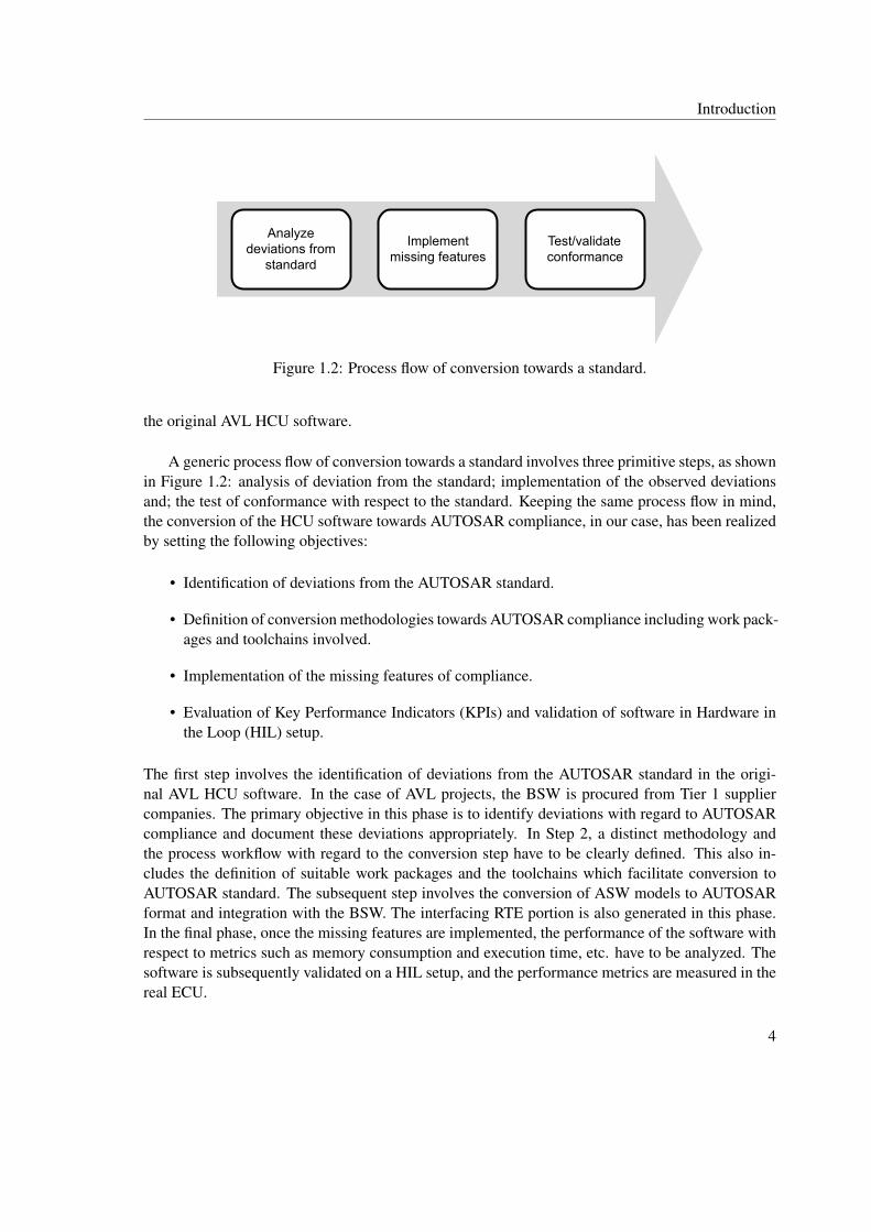
Figure 1.2: Process flow of conversion towards a standard.
the original AVL HCU software.
A generic process flow of conversion towards a standard involves three primitive steps, as shownin Figure 1.2: analysis of deviation from the standard; implementation of the observed deviationsand; the test of conformance with respect to the standard. Keeping the same process flow in mind,the conversion of the HCU software towards AUTOSAR compliance, in our case, has been realizedby setting the following objectives:
• Identification of deviations from the AUTOSAR standard.
• Definition of conversion methodologies towards AUTOSAR compliance including work pack-ages and toolchains involved.
• Implementation of the missing features of compliance.
• Evaluation of Key Performance Indicators (KPIs) and validation of software in Hardware inthe Loop (HIL) setup.
The first step involves the identification of deviations from the AUTOSAR standard in the origi-nal AVL HCU software. In the case of AVL projects, the BSW is procured from Tier 1 suppliercompanies. The primary objective in this phase is to identify deviations with regard to AUTOSARcompliance and document these deviations appropriately. In Step 2, a distinct methodology andthe process workflow with regard to the conversion step have to be clearly defined. This also in-cludes the definition of suitable work packages and the toolchains which facilitate conversion toAUTOSAR standard. The subsequent step involves the conversion of ASW models to AUTOSARformat and integration with the BSW. The interfacing RTE portion is also generated in this phase.In the final phase, once the missing features are implemented, the performance of the software withrespect to metrics such as memory consumption and execution time, etc. have to be analyzed. Thesoftware is subsequently validated on a HIL setup, and the performance metrics are measured in thereal ECU.
4

Introduction
1.4 Related Work
This section describes some research works already published in the field of migration from legacyimplementation to AUTOSAR and their relevance to this thesis. Comparisons are also made withsome related works from other areas in the embedded systems domain.
An approach for the conversion of legacy software to AUTOSAR architecture has been pre-sented by Daehyun et al. [5]. The authors propose some concepts of migration including allocationof the application software entities among various AUTOSAR Software Component (SWC) typesand apply them to a simple legacy software model for the interior lighting system. Although theauthors mention some conditions on BSW reusability, only a new BSW stack specific to AUTOSARhas been configured and used in their case-study for integration with the AUTOSAR ASW. More-over, the possibility of automating the conversion process to AUTOSAR has not been covered inthis work. This is necessary in the case of the ECU software system involving a higher number ofrelated software models. The work in this thesis, in contrast, investigates the likelihood of BSWreusability mentioned in the work by Daehyun et al. Additionally, due to vastness of the AVL HCUsoftware system comprising of about 40 software models, the possibility of using the automatedfeatures provided by tools such as MATLAB has also been examined for ASW conversion.
The work by James et al. [6] uses SystemDesk tool from dSPACE to automate the conversionfrom legacy software to AUTOSAR system. The authors use MATLAB scripting to convert ASWmodels to AUTOSAR format and eventually apply native Python Application Program Interfaces(APIs) from SystemDesk for system architecture modelling and RTE generation. However, owingto the non-availability of SystemDesk license, we chose to use automation features provided byMATLAB for ASW conversion in this thesis. Additionally, a separate RTE generator engine hasbeen implemented in MATLAB M-Script based on the work by Shiquan et al. [7].
Furthermore, none of the works described above focused on the handling of calibration andmeasurement variables in the AUTOSAR environment during conversion. The proper handling ofcalibration and measurement variables is necessary when a software system involving a higher num-ber of complex models is subjected to AUTOSAR conversion. In this thesis, the Parameter SWCtype specified in the AUTOSAR standard ([8], p.34) has been used for handling the calibration vari-ables.
Due to the relevance with AUTOSAR, some works in the topics of OSEK1 migration have alsobeen considered here. Denil et al. in [9] use wrappers to migrate a legacy Real Time OperatingSystem (RTOS) application to OSEK platform. Jochen and David in [10] clearly bring out the re-lationship of the OSEK standard with AUTOSAR and conclude that the migration from OSEK toAUTOSAR is just the addition of the extended concepts. In our case, a modification in the OS of
1Open Systems and their Interfaces for the Electronics in Motor Vehicles (OSEK) [11] is a previously establishedautomotive software standard. The AUTOSAR system service specifications are based on OSEK Operating Systems(OS) concepts. The AUTOSAR OS is considered an extended version of the OSEK OS [10].
5

Introduction
AVL HCU software is not required since the OS implemented by the BSW supplier is already com-pliant with OSEK [12]. However, it must be noted here that the BSW as a whole is not AUTOSARcompliant due to reasons mentioned in Section 2.2.4.
The following are some of the works referred from other domains in embedded systems in topicsrelated to migration. William in [13] discusses various aspects of migrating a legacy application tothe Linux platform. The author additionally mentions that there is no direct conversion step in thisregard and each feature of the legacy RTOS application must be mapped with its correspondingfeature in the Linux OS. Another example of software migration is the work by Franck et al. [14],where the authors use an automation framework to migrate a banking application software from oneplatform to the other. In contrast to the above discussed works, the work in this thesis does not focuson migration from one source platform to another target platform in its entirety, but rather deals withthe incorporation of AUTOSAR concepts of data access and interfacing (the RTE function calls) atthe application software level without actually changing the execution platform (the BSW and themicrocontroller hardware).
1.5 Thesis Structure
The rest of the thesis is structured as follows:
1. Chapter 2 provides a brief overview of AUTOSAR layered architecture and AVL HCU soft-ware architecture.
2. Chapter 3 presents various findings in the AUTOSAR compliance deviation analysis studiedacross the V-Model phases.
3. Chapter 4 explores the implementation decisions and infers on the AUTOSAR conversionapproach followed in this thesis.
4. Chapter 5 explains the automation scripts developed for ASW conversion, RTE generation,and the build process.
5. Chapter 6 describes the experimental setup and the results of the evaluation.
6. Chapter 7 concludes the findings in this thesis and provides some recommendations for fu-ture works.
6

2. Overview of AUTOSAR and AVL HCUSoftware Architecture
This chapter presents a general overview of AUTOSAR software architecture and a descriptionof each of its layers. Additionally, a description of the AVL HCU software architecture is alsoprovided. The AUTOSAR concepts covered in this section are primarily based on AUTOSARRelease Specifications 4.3, Classic Platform.
2.1 AUTOSAR Layered Architecture
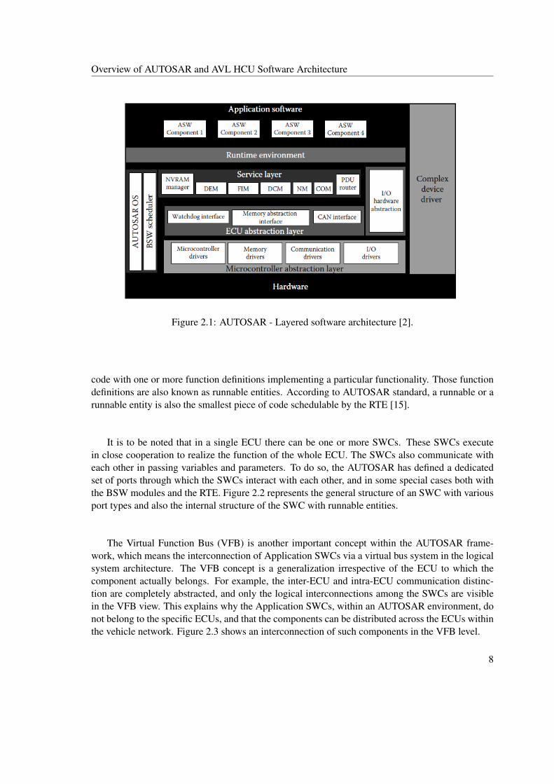
A model of software architecture has been proposed by the AUTOSAR standard for ECU develop-ment. The AUTOSAR software architecture is layered in structure and can basically be divided intothree layers hierarchically as: Application Software (ASW), Run Time Environment (RTE), andBasic Software (BSW). An overview of the AUTOSAR layered software architecture is shown inFigure 2.1. Although the functionality of each layer is unique in nature, the layers function coopera-tively to realize the task of the ECU system. The ASW is the functional part, wherein the functionalaspects of the system are implemented. The BSW forms the core of the system and provides theOperating Systems (OS) and other services to the upper layers. The RTE actuates the dynamicbehaviour of the system. The primary purpose of this layer is to support inter- and intra-ECU com-munication and also to interface the application (ASW) and core (BSW) part of the ECU software.
The three basic layers are bundled in such a way that the ASW is completely abstracted from theBSW by the RTE and that the application Software Components (SWCs) are not allowed to interactwith the BSW modules directly, but only via the RTE [2]. The following sections present a ratherdetailed account on each layer in specific.
2.1.1 Application Software
As pointed earlier, the ASW portion of the software houses the functional part of the ECU software.The ASW, however, is not coded as a single program implementing all the functionalities requiredfor the ECUs. It is rather compartmentalized into dedicated SWCs, wherein each SWC is a piece of
7
Overview of AUTOSAR and AVL HCU Software Architecture
Figure 2.1: AUTOSAR - Layered software architecture [2].
code with one or more function definitions implementing a particular functionality. Those functiondefinitions are also known as runnable entities. According to AUTOSAR standard, a runnable or arunnable entity is also the smallest piece of code schedulable by the RTE [15].
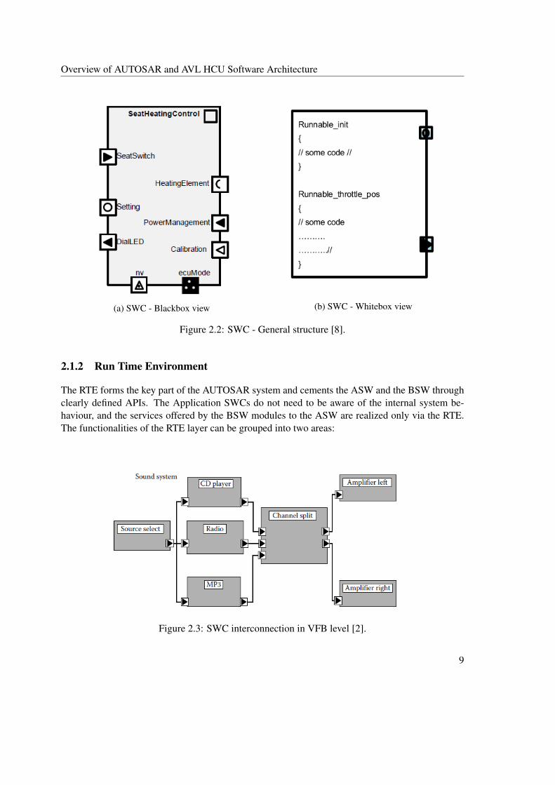
It is to be noted that in a single ECU there can be one or more SWCs. These SWCs executein close cooperation to realize the function of the whole ECU. The SWCs also communicate witheach other in passing variables and parameters. To do so, the AUTOSAR has defined a dedicatedset of ports through which the SWCs interact with each other, and in some special cases both withthe BSW modules and the RTE. Figure 2.2 represents the general structure of an SWC with variousport types and also the internal structure of the SWC with runnable entities.
The Virtual Function Bus (VFB) is another important concept within the AUTOSAR frame-work, which means the interconnection of Application SWCs via a virtual bus system in the logicalsystem architecture. The VFB concept is a generalization irrespective of the ECU to which thecomponent actually belongs. For example, the inter-ECU and intra-ECU communication distinc-tion are completely abstracted, and only the logical interconnections among the SWCs are visiblein the VFB view. This explains why the Application SWCs, within an AUTOSAR environment, donot belong to the specific ECUs, and that the components can be distributed across the ECUs withinthe vehicle network. Figure 2.3 shows an interconnection of such components in the VFB level.
8
Overview of AUTOSAR and AVL HCU Software Architecture
(a) SWC - Blackbox view (b) SWC - Whitebox view
Figure 2.2: SWC - General structure [8].
2.1.2 Run Time Environment
The RTE forms the key part of the AUTOSAR system and cements the ASW and the BSW throughclearly defined APIs. The Application SWCs do not need to be aware of the internal system be-haviour, and the services offered by the BSW modules to the ASW are realized only via the RTE.The functionalities of the RTE layer can be grouped into two areas:
Figure 2.3: SWC interconnection in VFB level [2].
9

Overview of AUTOSAR and AVL HCU Software Architecture
• Realization of communication paradigms among Application SWCs.
• Interfacing the ASW and the BSW.
In order to support the communication between the Application SWCs, the RTE provides an APIheader, using which the Application SWCs can be coded. The RTE header file consists of functionprototypes for realizing the port communication between the SWCs. An example of RTE functionprototype is Rte_send_portA_d(), where an SWC sends data element d via port A [2]. The RTE alsochecks for "data consistency" during communication [2].
The RTE additionally includes task bodies, which hold the function calls to the runnable entities.These are the dedicated tasks of the OS to which the runnable entities are mapped. The problemof ’which runnable entity belongs to which OS task’ is resolved in the RTE configuration phase(Section 3.5.2). The OS tasks also await notifications from RTE events during execution. Further,the scheduling of these OS tasks is handled by the Basic Software Scheduler (BSS), which is theglobal scheduler in the AUTOSAR environment. The BSS is a part of the OS situated in the BSW[15]. Moreover, the RTE also acts as a medium for the services provided by the BSW modules tothe upper layers. AUTOSAR has defined standardized port interfaces (Section 3.3.2) for handlingthe BSW services to the application layer.
2.1.3 Basic Software
This section describes the BSW portion - the third layer in the AUTOSAR software architecture.The content described in this section is based on [16]. As indicated earlier, the BSW forms thecore part of the AUTOSAR system. The BSW can be further subdivided into the following layers:Service Layer, ECU Abstraction Layer, Microcontroller Abstraction Layer (MCAL) and ComplexDrivers [16]. The BSW layers are ordered hierarchically from hardware specific drivers to man-agerial layers and are abstracted from each other via standardized API calls. However, the complexdriver is housed as an independent layer. The basic arrangement of these layers within the scope ofthe BSW can be seen in Figure 2.4.
The software layer written over the microcontroller hardware level is the Microcontroller Ab-straction Layer (MCAL). As the name suggests, the MCAL layer is in "direct access" with themicrocontroller hardware and abstracts the layer situated above it via standardized interfaces [16].The MCAL layer provides interfaces for the upper layers to access individual peripherals of the mi-crocontroller. Moreover, this layer also contains drivers such as communication drivers, I/O driversand memory drivers for microcontroller on-chip peripherals.
The ECU Abstraction Layer defines a broader group of hardware peripherals in addition tothe microcontroller specific peripherals. It provides interfaces for both microcontroller on-chip pe-ripherals as well as external hardware like a watchdog timer. However, the ECU abstraction layercannot access the microcontroller directly, but only via the MCAL layer.
10

Overview of AUTOSAR and AVL HCU Software Architecture
Figure 2.4: BSW layers [16].
The Complex Drivers form a separate layer and are situated independently from the hierarchi-cal structure of the BSW layered architecture, although communication may be possible with otherBSW modules. This layer is mainly provided for "migration purposes" - to accommodate featuresthat are not AUTOSAR compliant, or to incorporate any "time-critical constraints" into the AU-TOSAR environment [16].
The topmost layer in the BSW hierarchy is the Service Layer. It is the managerial layer forall the services provided to the RTE and the ASW. Some of the services provided are OS services,memory services, communication services, and mode management, etc. The BSW hierarchicalmodel can be further categorized into various functional groups based on their application scope, asshown in Figure 2.5.
The System Services are related to the group of services such as OS, mode management, diag-nostics event management, etc. Normally, these services are used by the application layer as wellas other BSW modules. The Memory Services form the management group for the Non-volatileRandom Access Memory (NVRAM) access. The NVRAM manager (NvM) provides necessaryservices and routines for the ASW for reading and writing non-volatile data into the NVRAM. Thecrypto services are used in the management and access of "cryptographic primitives" [16].
The functional group responsible for the inter-ECU communication by transferring the data viathe bus lines is the Communication (COM) Manager. In addition, the COM manager acting asDiagnostics Communication Manager (DCM) also handles the communication capabilities with ex-ternal diagnostic tools. The COM layer has dedicated COM stacks and Protocol Data Unit (PDU)
11

Overview of AUTOSAR and AVL HCU Software Architecture
Figure 2.5: BSW functional groups [16].
router, which can seamlessly handle protocols such as Controller Area Network (CAN), Local In-terconnect Network (LIN) and FlexRay. Similarly, the Off-board Communication services arerelated to "Vehicle-2-X" communication over wireless medium [16].
The I/O Hardware Abstraction is related to the sensor I/O read and write functionalities and isconsidered a part of VFB despite being a BSW software module. The module communicates withthe application layer via port interfaces on one side, and with the MCAL layer on the other sidethrough standardized APIs.
2.1.4 BSW Conformance Classes
This section describes ways of measuring compliance levels towards the AUTOSAR standard andis based on [2]. The Implementation Conformance Classes (ICC) measure the degree of the con-formance of various automotive software implementations towards the AUTOSAR standard. Thesecategories have been defined from ICC1 to ICC3 keeping in mind the step by step process of migra-tion from non-AUTOSAR models to AUTOSAR models. The conformance classes, however, aremeasured only with respect to the RTE and the BSW modules.
ICC1
In the ICC1 category, the RTE functionality can be integrated with the BSW and implemented as asingle entity. The BSW part is not required to follow the AUTOSAR conformed implementation.For this reason, the suppliers are free to add their own implementations in the BSW cluster. How-ever, the interfaces between the ASW and the BSW still need to be AUTOSAR conformed, and the
12
Overview of AUTOSAR and AVL HCU Software Architecture
BSW cluster shall offer all the necessary functionalities mentioned in the AUTOSAR specifications[2].
ICC2
In the ICC2 category, the BSW is classified as the "cluster" of modules based on their functionalitysuch as the RTE part, the OS part, and the COM stack, etc. [2]. The BSW modules are also termedas "BSW clusters" [17]. An individual or a set of BSW clusters can be obtained from differentsuppliers and integrated as a BSW stack [2].
ICC3
The ICC3 category must follow the fullest AUTOSAR conformance. All the interfaces betweenthe ASW and the BSW and the abstraction levels between various BSW layers must comply withAUTOSAR requirements [2]. The BSW is considered as a single-layered entity with the layersabstracted from each other via standardized interfaces. Unlike ICC2, the RTE layer in the ICC3category is considered an independent layer from the BSW structure.
2.2 AVL Hybrid Control Unit Software Architecture Overview
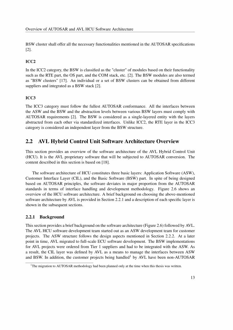
This section provides an overview of the software architecture of the AVL Hybrid Control Unit(HCU). It is the AVL proprietary software that will be subjected to AUTOSAR conversion. Thecontent described in this section is based on [18].
The software architecture of HCU constitutes three basic layers: Application Software (ASW),Customer Interface Layer (CIL), and the Basic Software (BSW) part. In spite of being designedbased on AUTOSAR principles, the software deviates in major proportion from the AUTOSARstandards in terms of interface handling and development methodology. Figure 2.6 shows anoverview of the HCU software architecture. A brief background on choosing the above-mentionedsoftware architecture by AVL is provided in Section 2.2.1 and a description of each specific layer isshown in the subsequent sections.
2.2.1 Background
This section provides a brief background on the software architecture (Figure 2.6) followed by AVL.The AVL HCU software development team started out as an ASW development team for customerprojects. The ASW structure follows the design aspects mentioned in Section 2.2.2. At a laterpoint in time, AVL migrated to full-scale ECU software development. The BSW implementationsfor AVL projects were ordered from Tier 1 suppliers and had to be integrated with the ASW. Asa result, the CIL layer was defined by AVL as a means to manage the interfaces between ASWand BSW. In addition, the customer projects being handled1 by AVL have been non-AUTOSAR
1The migration to AUTOSAR methodology had been planned only at the time when this thesis was written.
13

Overview of AUTOSAR and AVL HCU Software Architecture
Application Software
Customer Interface Layer
Basic Software
Hardware
Figure 2.6: HCU software architecture. Adapted from [18].
projects. Therefore, AVL follows their own software development methodology which includesprocurement of BSW from suppliers, development of ASW and CIL, and software integration ofBSW and ASW.
2.2.2 Application Software
The ASW structure of the HCU software has been developed by AVL. Similar to the ASW in AU-TOSAR layered architecture described in Section 2.1.1, the ASW structure in the AVL proprietarysoftware constitutes individual SWCs making up for the software behaviour. The ASW behaviour isalso coded in the form of runnable entities. The SWCs in the AVL HCU software are also distinctlygrouped into various functional groups based on their functionality.
SWC2
SWC3
SWC1 SWC2
SWC3
SWC1
Functional Group1 Functional Group2
Software System
Figure 2.7: AVL HCU software - ASW structure.
14

Overview of AUTOSAR and AVL HCU Software Architecture
Figure 2.7 provides an understanding of the classification of SWCs in AVL HCU software basedon their associated functional groups. The set of all the SWCs in the ASW along with the functionalgroups constitutes the complete software system of the HCU. In contrast to AUTOSAR, whereRTE function calls are used for ASW communication, the communication among the SWCs ishandled via static global variables. In the ASW code level, this property is directly adopted whena non-AUTOSAR type code is generated from MATLAB/Simulink models. The reader can refer toSection 3.4.1 for more details on the AVL software code generation.
2.2.3 Customer Interface Layer
AVL defines the Customer Interface layer (CIL) as the interfacing layer between ASW and BSWproviding a bidirectional signal interface. The CIL layer has been designed to handle all possibleinterfaces between ASW and BSW. The role of the CIL layer can be understood from Figure 2.8.The HCU Software architecture document [18] mentions the following functionalities to be offeredat the CIL level:
Software System
NVM Mapping UDS CallbacksCAN Message to Signal Mapping
Hardware Signal Mapping
UDSDEMNVM
CAN Buffer Hardware I/O Drivers
Hardware
ASW
CIL
BSW
Figure 2.8: Role of layers in HCU software architecture. Adapted from [18].
• Providing signal interfaces to the ECU I/O signals.
• Interfacing signals to be transmitted over CAN bus lines. Additionally performing CANsignal validity checks, etc.
• Interfacing diagnostic event signals.
15

Overview of AUTOSAR and AVL HCU Software Architecture
• Providing interfaces for the variables to be loaded into NVRAM.
• Invoking the ASW runnable entities with OS task execution.
2.2.4 Basic Software
COM Service
NVRAMSystem
ServicesDiag
Service
Task Bodies
BASIC SOFTWARE
API Interfaces provided by BSW
Supplier to Application layer
Figure 2.9: BSW structure - AVL HCU software.
The BSW portion of AVL HCU software is procured from the supplier along with the hardware.A schematic of the BSW is shown in Figure 2.9. The ’sky-blue’ portion indicates the core part of theBSW, which provides the class of functionalities related to the OS, communication and diagnosticservices, memory services and other software drivers, etc. [19]. The implementation of the BSW isproprietary to the supplier. The supplier additionally defines APIs (marked ’purple’ in Figure 2.9)and task bodies for providing the BSW services to the upper layers. The API interfaces are usedto exchange information such as the CAN signals, diagnostic callbacks, I/O and NVRAM signals,etc., between the BSW and the ASW. The task bodies are used to invoke the ASW runnable entities.
The exact software architecture used in the BSW implementation is not clearly known as it isnot indicated by the supplier in the BSW documentation, and additionally the BSW is delivered toAVL as compiled object files. Hence it has been assumed that the BSW implementation is supplierproprietary and are not necessarily based on AUTOSAR BSW specifications. Additionally, the APIinterfaces to the upper layers are also supplier-specific (defined with respect to the CIL layer) andare not based on AUTOSAR specifications. Hence the BSW, as a whole entity, cannot be inferredto be AUTOSAR compliant.
16

3. AUTOSAR Compliance Deviation Anal-ysis
In order to convert the AVL HCU software towards AUTOSAR compliance, it is important to under-stand the deviations from the AUTOSAR standard. The V-Model type of SDLC has been chosen,since it is a clear representation of the software development process and is also widespread in us-age across the industries. The deviations from AUTOSAR have been studied across the V-Modelprocess flow and presented in this chapter.
3.1 Deviation Analysis along V-Model Phases
Like Waterfall and Spiral Model, V-Model is a type of SDLC representing the sequential stepsinvolved in the software development process [20]. The V-Model flow of software developmentaims at seamless and fine-grained control of the development and testing process. As the case withsoftware development in other areas, the V-Model process flow methodology is also widespread inusage in automotive software development. The methodology describes a "series of process stages"from requirements, high-level design to low-level implementation in the design phase (left trunkof V-diagram), and from unit testing until acceptance testing in the validation phase (right trunk ofV-diagram) [21], as shown in Figure 3.1.
While applying the V-Model methodology in the case of automotive software development, thework stages across the design and the validation phases are appropriately shared among the OEMs,Tier 1, supplier companies and service providers. The software development life-cycle starts withthe requirements phase. The system and component requirements based on customer expectationsand other boundary conditions are prepared by the OEMs in this phase and are quoted to varioussupplier companies.
The design and implementation phase usually takes place at the supplier side of the particularcomponent (e.g. ECUs). The high-level design involves the design of architectural concepts of theparticular software. The low-level design refers to the design of granular concepts such as models,
17
AUTOSAR Compliance Deviation Analysis
Business Requirements
System Requirements
High Level Design
Low Level Design
Coding
Acceptance Testing
System Testing
Integration Testing
Functional Testing
Unit Testing
Deviations at Requirements Level
Deviations at Interface Level
Deviations at Code Generation Level
Deviations at Software Integration Level
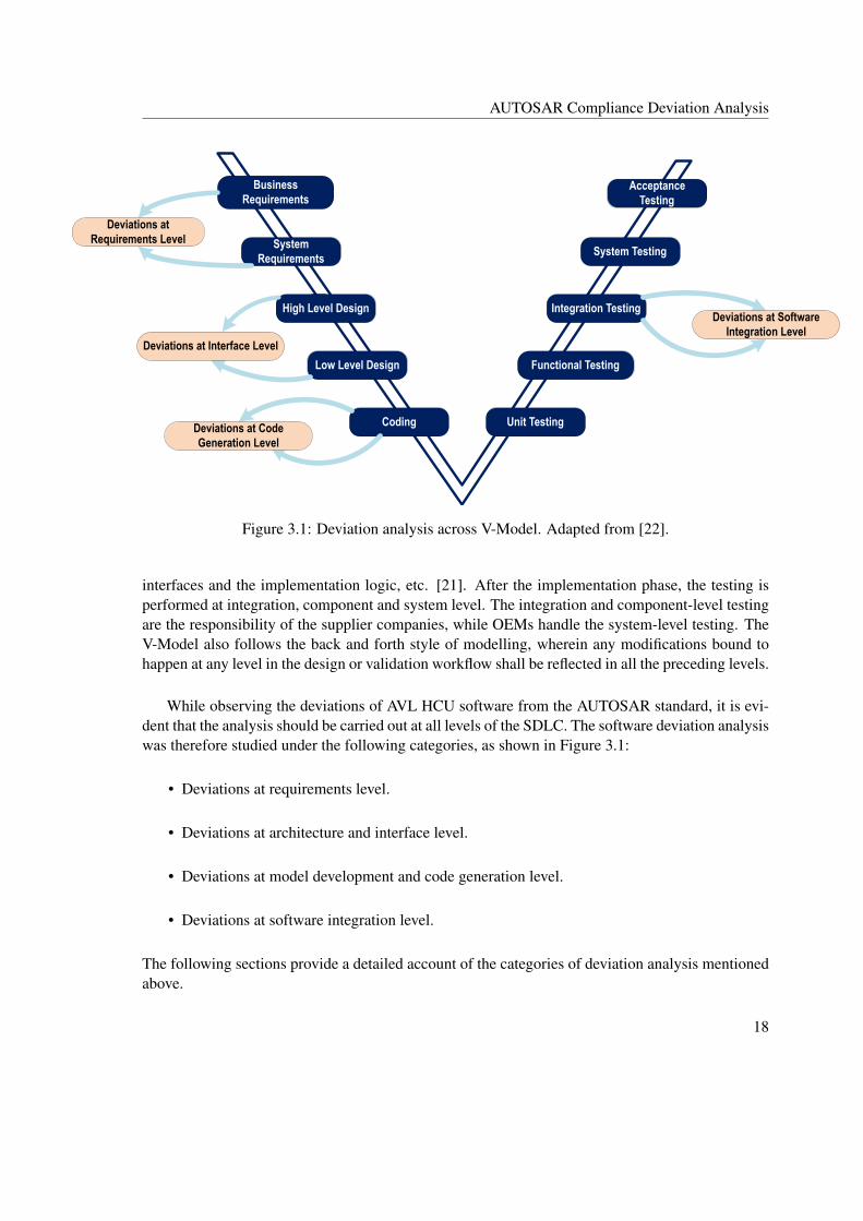
Figure 3.1: Deviation analysis across V-Model. Adapted from [22].
interfaces and the implementation logic, etc. [21]. After the implementation phase, the testing isperformed at integration, component and system level. The integration and component-level testingare the responsibility of the supplier companies, while OEMs handle the system-level testing. TheV-Model also follows the back and forth style of modelling, wherein any modifications bound tohappen at any level in the design or validation workflow shall be reflected in all the preceding levels.
While observing the deviations of AVL HCU software from the AUTOSAR standard, it is evi-dent that the analysis should be carried out at all levels of the SDLC. The software deviation analysiswas therefore studied under the following categories, as shown in Figure 3.1:
• Deviations at requirements level.
• Deviations at architecture and interface level.
• Deviations at model development and code generation level.
• Deviations at software integration level.
The following sections provide a detailed account of the categories of deviation analysis mentionedabove.
18
AUTOSAR Compliance Deviation Analysis
3.2 Deviations at Requirements Level
AVL1 uses the requirement specifications in order to quote the supplier about the BSW and hard-ware requirements. The deviations inferred in the requirements level can be shown in the belowcategories. The descriptions in the below sections are based on AVL’s BSW requirement document[19].
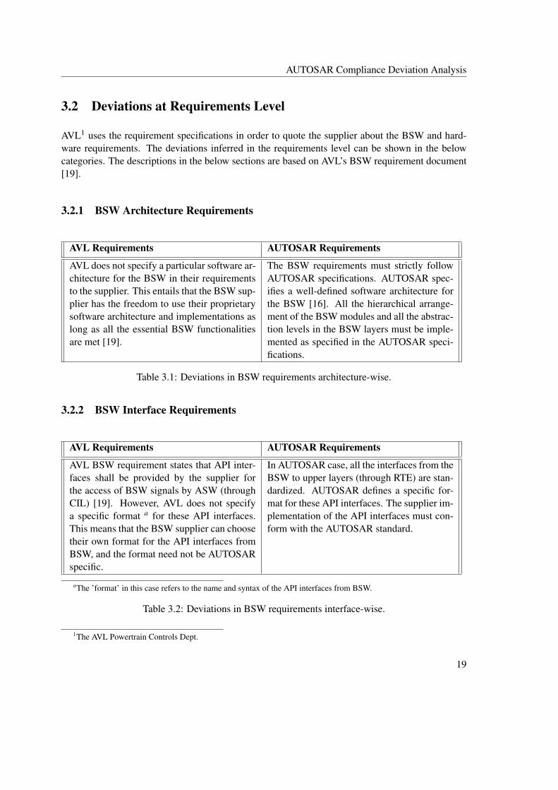
3.2.1 BSW Architecture Requirements
AVL Requirements AUTOSAR Requirements
AVL does not specify a particular software ar-chitecture for the BSW in their requirementsto the supplier. This entails that the BSW sup-plier has the freedom to use their proprietarysoftware architecture and implementations aslong as all the essential BSW functionalitiesare met [19].
The BSW requirements must strictly followAUTOSAR specifications. AUTOSAR spec-ifies a well-defined software architecture forthe BSW [16]. All the hierarchical arrange-ment of the BSW modules and all the abstrac-tion levels in the BSW layers must be imple-mented as specified in the AUTOSAR speci-fications.
Table 3.1: Deviations in BSW requirements architecture-wise.
3.2.2 BSW Interface Requirements
AVL Requirements AUTOSAR Requirements
AVL BSW requirement states that API inter-faces shall be provided by the supplier forthe access of BSW signals by ASW (throughCIL) [19]. However, AVL does not specifya specific format a for these API interfaces.This means that the BSW supplier can choosetheir own format for the API interfaces fromBSW, and the format need not be AUTOSARspecific.
In AUTOSAR case, all the interfaces from theBSW to upper layers (through RTE) are stan-dardized. AUTOSAR defines a specific for-mat for these API interfaces. The supplier im-plementation of the API interfaces must con-form with the AUTOSAR standard.
aThe ’format’ in this case refers to the name and syntax of the API interfaces from BSW.
Table 3.2: Deviations in BSW requirements interface-wise.
1The AVL Powertrain Controls Dept.
19

AUTOSAR Compliance Deviation Analysis
3.3 Architectural and Interface Level Deviations
3.3.1 Interface Handling in AVL HCU Software
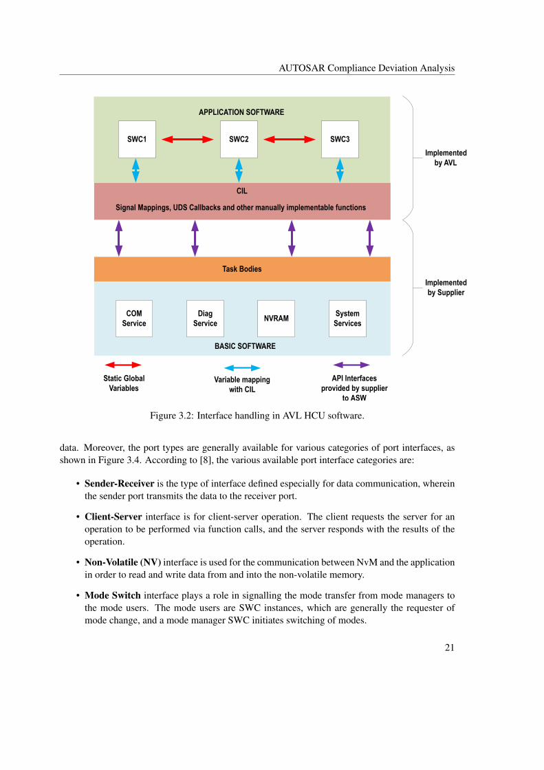
This section describes the interface handling in AVL HCU software. The AVL HCU software archi-tecture has been designed by AVL and is architecturally comparable to the AUTOSAR architectureshown in Figure 2.1. Nevertheless, there are inherent differences in the low-level design aspectssuch as interface handling. Figure 3.2 shows an illustration of the interface handling in AVL HCUsoftware. As indicated in Section 2.2.4, the supplier provides the BSW along with the API inter-faces to the upper layers and the task bodies.
The CIL layer is implemented by AVL. The API interfaces (marked ’purple’ in Figure 3.2) pro-vided by the supplier are used to integrate the CIL layer with the BSW. The task bodies are alsofilled with function calls to the ASW runnable entities at the CIL layer level. Alternatively, it canalso be understood that the CIL is not a standardized layer; and CIL has been defined by AVL tomanage the interfaces provided by the BSW to the application layer. In short, all the interfacesfrom ASW to BSW are handled only via the CIL layer. Additionally, any manually implementablefunctionalities such as CAN CRC check, and hardware fault detection, etc., are also implementedat the CIL layer level.
At the ASW level, communication among the SWCs involves static global variables (marked’red’ in Figure 3.2). The diagnostic, NVRAM and mode information interfaces are routed onlythrough the CIL layer via variable mapping or function calls (marked ’blue’ in Figure 3.2).
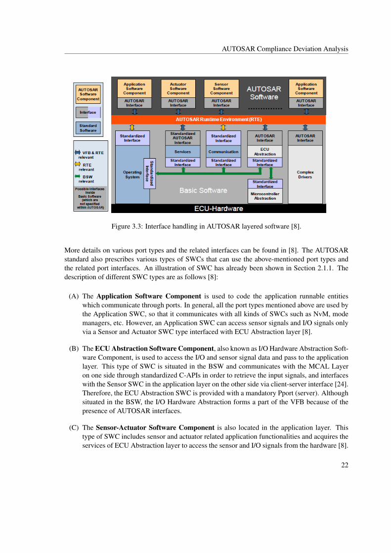
3.3.2 Interface Handling in AUTOSAR Standard
This section provides details on the interface handling in AUTOSAR software models. An illustra-tion of types of interfaces used in the AUTOSAR standard is shown in Figure 3.3.
The interfaces have been classified into three types based on their scope of application withinthe layers. The standardized interfaces (Figure 3.3) are defined by the AUTOSAR standard. Theseinterfaces are standardized C-APIs and are used only by the BSW modules while communicatingwith each other [16]. The AUTOSAR interfaces, on the other hand, define port communicationbetween the Application SWCs [16]. These interfaces are not standardized by AUTOSAR, and thenaming conventions are based on the name of the port variables. The third category of interfaces,the standardized AUTOSAR interfaces, refer to the standardized API calls provided by the ser-vice layer to the Application SWCs, for example, the diagnostic services offered by the DiagnosticEvent Manager (DEM) to the application layer [16, 23].
Additionally, AUTOSAR defines port types and port interfaces for different communicationtypes involved among the SWCs. In the high level, the port types can be classified into ’Pport’ and’Rport’ [8]. The Pport is the provider of the data, and the Rport is the receiver or requester of the
20
AUTOSAR Compliance Deviation Analysis
SWC1 SWC2 SWC3
APPLICATION SOFTWARE
CIL
COM Service
NVRAMSystem
ServicesDiag
Service
Task Bodies
BASIC SOFTWARE
Implemented by AVL
Implemented by Supplier
Static Global Variables
Variable mapping with CIL
API Interfaces provided by supplier
to ASW
Signal Mappings, UDS Callbacks and other manually implementable functions
Figure 3.2: Interface handling in AVL HCU software.
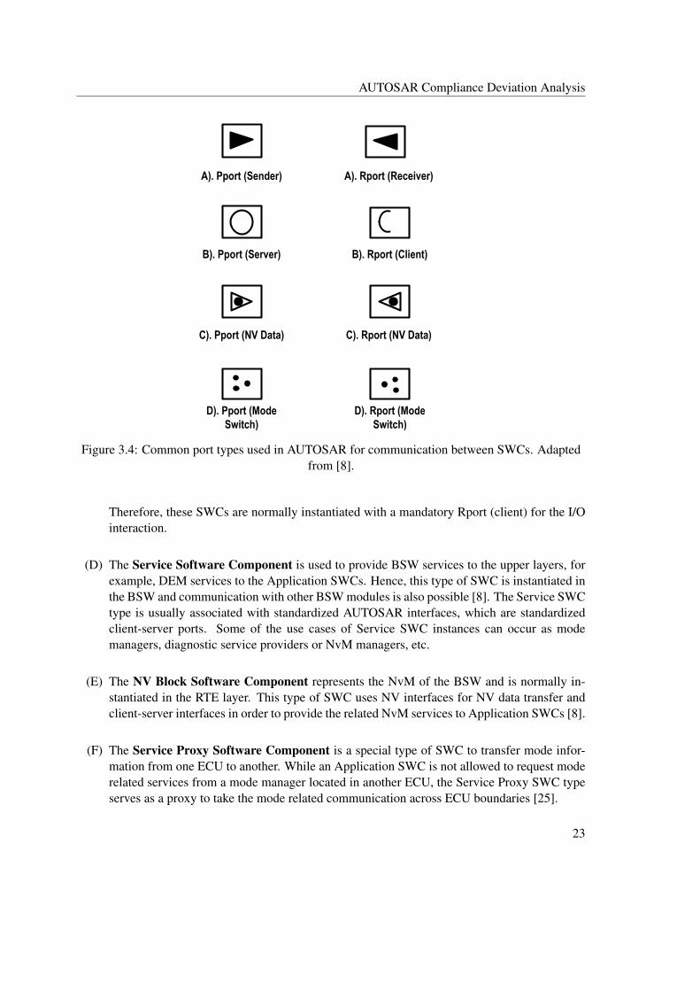
data. Moreover, the port types are generally available for various categories of port interfaces, asshown in Figure 3.4. According to [8], the various available port interface categories are:
• Sender-Receiver is the type of interface defined especially for data communication, whereinthe sender port transmits the data to the receiver port.
• Client-Server interface is for client-server operation. The client requests the server for anoperation to be performed via function calls, and the server responds with the results of theoperation.
• Non-Volatile (NV) interface is used for the communication between NvM and the applicationin order to read and write data from and into the non-volatile memory.
• Mode Switch interface plays a role in signalling the mode transfer from mode managers tothe mode users. The mode users are SWC instances, which are generally the requester ofmode change, and a mode manager SWC initiates switching of modes.
21
AUTOSAR Compliance Deviation Analysis
Figure 3.3: Interface handling in AUTOSAR layered software [8].
More details on various port types and the related interfaces can be found in [8]. The AUTOSARstandard also prescribes various types of SWCs that can use the above-mentioned port types andthe related port interfaces. An illustration of SWC has already been shown in Section 2.1.1. Thedescription of different SWC types are as follows [8]:
(A) The Application Software Component is used to code the application runnable entitieswhich communicate through ports. In general, all the port types mentioned above are used bythe Application SWC, so that it communicates with all kinds of SWCs such as NvM, modemanagers, etc. However, an Application SWC can access sensor signals and I/O signals onlyvia a Sensor and Actuator SWC type interfaced with ECU Abstraction layer [8].
(B) The ECU Abstraction Software Component, also known as I/O Hardware Abstraction Soft-ware Component, is used to access the I/O and sensor signal data and pass to the applicationlayer. This type of SWC is situated in the BSW and communicates with the MCAL Layeron one side through standardized C-APIs in order to retrieve the input signals, and interfaceswith the Sensor SWC in the application layer on the other side via client-server interface [24].Therefore, the ECU Abstraction SWC is provided with a mandatory Pport (server). Althoughsituated in the BSW, the I/O Hardware Abstraction forms a part of the VFB because of thepresence of AUTOSAR interfaces.
(C) The Sensor-Actuator Software Component is also located in the application layer. Thistype of SWC includes sensor and actuator related application functionalities and acquires theservices of ECU Abstraction layer to access the sensor and I/O signals from the hardware [8].
22
AUTOSAR Compliance Deviation Analysis
A). Pport (Sender) A). Rport (Receiver)
B). Pport (Server) B). Rport (Client)
C). Pport (NV Data) C). Rport (NV Data)
D). Pport (Mode Switch)
D). Rport (Mode Switch)
Figure 3.4: Common port types used in AUTOSAR for communication between SWCs. Adaptedfrom [8].
Therefore, these SWCs are normally instantiated with a mandatory Rport (client) for the I/Ointeraction.
(D) The Service Software Component is used to provide BSW services to the upper layers, forexample, DEM services to the Application SWCs. Hence, this type of SWC is instantiated inthe BSW and communication with other BSW modules is also possible [8]. The Service SWCtype is usually associated with standardized AUTOSAR interfaces, which are standardizedclient-server ports. Some of the use cases of Service SWC instances can occur as modemanagers, diagnostic service providers or NvM managers, etc.
(E) The NV Block Software Component represents the NvM of the BSW and is normally in-stantiated in the RTE layer. This type of SWC uses NV interfaces for NV data transfer andclient-server interfaces in order to provide the related NvM services to Application SWCs [8].
(F) The Service Proxy Software Component is a special type of SWC to transfer mode infor-mation from one ECU to another. While an Application SWC is not allowed to request moderelated services from a mode manager located in another ECU, the Service Proxy SWC typeserves as a proxy to take the mode related communication across ECU boundaries [25].
23

AUTOSAR Compliance Deviation Analysis
(G) The Parameter Software Component is used as a container for all the global calibrationparameters. The Parameter SWC uses parameter interfaces (a type of Sender port) to sharethese calibration parameters across Application SWCs [8].
Standardized Interfaces (BSW - BSW)
Standardized Interfaces (BSW - RTE)
Communication across ECU boundaries
Port communication
Figure 3.5: An illustration of interface handling in AUTOSAR environment using port types andSWC types. Adapted from [8].
24
AUTOSAR Compliance Deviation Analysis
An illustration of interface handling using different SWC types and port types is shown in Figure 3.5.This example shows an ECU software module with two SWC instances present in the applicationlayer: SeatHeatingControl, an Application SWC, and HeatingDial, a Sensor SWC type. Boththe SWCs communicate with each other and also with other BSW modules through various portinterfaces. All the communication mechanisms are handled via the RTE (’red’ portion in Figure3.5). It can be seen that the communication between the SWCs in the application layer involveseither sender-receiver or client-server ports. The communication with the BSW, on the other hand,involves interface categories such as the NV data transfer, COM interface, mode transfer, and I/Odata access, etc. The mode-switch ports are used to transfer the mode information from ECU statemanager in BSW to Application SWC SeatHeatingControl. In the case of non-volatile (NV) datahandling, an NV Block type SWC is configured in the RTE, which represents the NvM and usesNV ports and standardized services from NvM to read and store the NV signals into NVRAM[26]. Besides, the COM stack is responsible for handling the inter-ECU communication mechanisminvolving external bus lines (e.g. CAN). In the use case shown in Figure 3.5, the informationrelated to the power management interface (this information is received externally) is read by theCOM stack and mapped to the receiver port of SeatHeatingControl at the RTE level. The ECUAbstraction SWC type interfaced with the Sensor component HeatingDial is used for accessing theI/O and sensor signals. As indicated earlier, the ECU Abstraction SWC type, in the use case shownin Figure 3.5, acts as a server and provides services related to I/O signals read/write to the SensorComponent using a server port. The port type indicated in the leftmost corner of SeatHeatingControlis the calibration interface. The use case of this type of interface includes the calibration parameteraccess from an external Parameter SWC type, wherein all the global calibration parameters arewritten. Apart from the interface categories discussed above, it can also be noted that the BSWmodules beneath the RTE use only standardized APIs for communication among them and alsowith the RTE (shown ’blue’ and ’yellow’ in Figure 3.5).
3.3.3 Differences in Scheduling Concepts
This section compares the scheduling approaches for runnable entities followed in the AVL HCUsoftware and the AUTOSAR standard. The scheduling concepts used in both the software modelsare almost similar in approach: the task bodies are used to invoke the runnable entities. In AVLHCU software, the task bodies are provided by the BSW supplier as mentioned in Section 2.2.4,wherein the function calls to the runnable entities are included by AVL. In the AUTOSAR stan-dard, the mapping of the task bodies to runnable entities is determined in the RTE configurationphase (Section 3.5.2) [15]. It is important to introduce the task types: basic and extended beforewe discuss further on the scheduling concepts. A basic task does not terminate by itself due to awaiting state. An extended task has OS events associated with it and it has wait points that requirethe occurrence of the associated events to proceed with the task execution [27]. The discussion inthis section is limited to the relationship between the OS tasks and runnable entities and does notcover in detail the scheduling concepts involved at the OS level.
In the case of AVL HCU software, the BSW supplier provides a total of four task bodies, whichare also basic tasks with different periodicities (1ms, 5ms, 10ms, and 100ms, etc.), for scheduling
25

AUTOSAR Compliance Deviation Analysis
the runnable entities. The scheduling algorithm used by the BSW supplier for these tasks and thepre-configured priorities are not visibly known since these are supplier-specific implementation inthe BSW object files delivered to AVL. Among the tasks mentioned above, only the 10ms task hasbeen used by AVL to invoke the ASW runnable entities. An illustration of a task body with runnableentities is shown in Figure 3.6. For illustrative purposes, the task name has been chosen as T1 andthe runnable entities have been named from Runnable_1 to Runnable_n. It can be seen from Fig-ure 3.6 that the runnable entities (Runnable_1 to Runnable_n) are invoked sequentially as the T1is scheduled for every 10ms. The complete execution of task T1 along with the runnable entitiesoccurs well within the next arrival time of T1. A possible reason for AVL to use the 10ms taskis to align the task runtime with the cycle-time of CAN message, which is 10ms for all the HCUmessages. Besides, the order of invocation of the runnable entities is determined by the executionorder generated by the HCU software system model via the Model-in-the-Loop (MIL) simulation.Furthermore, it can be seen from Figure 3.6 that no events, alarms or extended task types are used inthe scheduling concept of AVL HCU software. Since the runnable entities are executed sequentiallyone after another, there is no synchronized execution among the runnable entities.
Referring to Figure 3.7, in the AUTOSAR standard, there is a provision to use more than onetask type (basic or extended) depending on the application context. The AUTOSAR standard definesRTE events, which are also the means to trigger the execution of runnable entities [15]. In addition,the runnable entities can be classified into category 1, in which the runnable has no wait points, andcategory 2, in which the runnable has one or more wait points. These wait points are resolved by the
Task Bodies
Task T1{ Runnable_1(); Runnable_2(); Runnable_3(); ……. ……. Runnable_n();}
Task: T1Periodicity: 10msType: Basic Task
Figure 3.6: An example of a task body used to invoke ASW runnable entities in AVL HCUsoftware.
26
AUTOSAR Compliance Deviation Analysis
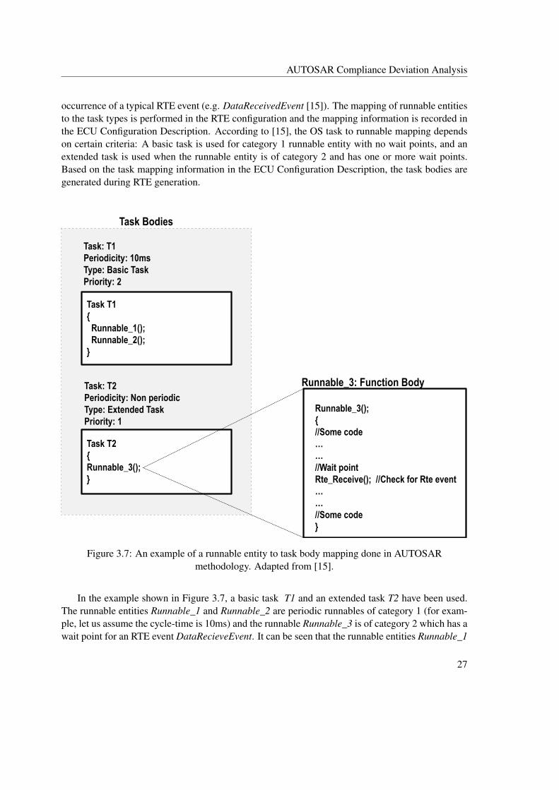
occurrence of a typical RTE event (e.g. DataReceivedEvent [15]). The mapping of runnable entitiesto the task types is performed in the RTE configuration and the mapping information is recorded inthe ECU Configuration Description. According to [15], the OS task to runnable mapping dependson certain criteria: A basic task is used for category 1 runnable entity with no wait points, and anextended task is used when the runnable entity is of category 2 and has one or more wait points.Based on the task mapping information in the ECU Configuration Description, the task bodies aregenerated during RTE generation.
Task Bodies
Task T1{ Runnable_1(); Runnable_2();}
Task: T1Periodicity: 10msType: Basic TaskPriority: 2
Task T2{Runnable_3();}
Task: T2Periodicity: Non periodicType: Extended TaskPriority: 1
Runnable_3();{//Some code……//Wait pointRte_Receive(); //Check for Rte event ……//Some code}
Runnable_3: Function Body
Figure 3.7: An example of a runnable entity to task body mapping done in AUTOSARmethodology. Adapted from [15].
In the example shown in Figure 3.7, a basic task T1 and an extended task T2 have been used.The runnable entities Runnable_1 and Runnable_2 are periodic runnables of category 1 (for exam-ple, let us assume the cycle-time is 10ms) and the runnable Runnable_3 is of category 2 which has await point for an RTE event DataRecieveEvent. It can be seen that the runnable entities Runnable_1
27

AUTOSAR Compliance Deviation Analysis
and Runnable_2 are mapped to task T1 in the RTE configuration phase. The sequence of executionfor these runnable entities is also specified beforehand in the configuration phase and is available inthe ECU Configuration Description. Additionally, the Runnable_3 is mapped to the extended taskT2. In can also be seen that, in the function body of Runnable_3, the wait point for checking theoccurrence of RTE event DataRecieveEvent is implemented using the RTE API Rte_Receive() [15].The priorities of the tasks to which the runnable entities are mapped are also decided during the OSconfiguration phase [27]. In the example shown in Figure 3.7, the priorities have been assumed ’1’for task T2 and ’2’ for task T1.
3.4 Deviation at Model Development and Code Generation Level
This section compares the model development aspects of AVL’s methodology and AUTOSARmethodology.
3.4.1 Model Development Aspects in AVL HCU Software
In this section, the model development process of AVL HCU software and the related softwaretools used are explained. As shown in Figure 3.8, the software development process begins withthe definition of the system requirements. The system in this context refers to the system of all thepowertrain ECUs2 developed by AVL. From the system requirements, the subset of requirementsrelated to the HCU module is filtered out and the ECU architecture is designed. The ECU designstep focuses on the definition of all the SWCs within the HCU software system and ECU labelssuch as the I/O signals, calibration, and measurement variables and system constants, etc. The cal-ibration variables, in this case, can also include single parameters, axes (1D arrays) and maps (2Darrays). The Automotive Data Dictionary (ADD) [28] tool is used to manage all the ECU labels.The ADD project is created as a separate container stored as .ddx files for each SWC model andthe I/O and calibration parameters to be used in the model are defined. The .ddx is the file formatof an ADD database containing the ECU labels of a particular SWC model [28]. The ADD is alsointegrated with the Maestra environment in the back-end3 and is responsible for keeping the *.ddxfile up-to-date with the variable modifications.
The SWC design phase (from Figure 3.8) involves modelling the Application SWCs and gener-ating the ASW code from SWC models using code-generators. The SWC models are developed us-ing a dedicated model-based development tool (e.g. MATLAB/Simulink, dSpace TargetLink, etc.).In the case of AVL HCU software, the SWC models are developed using TargetLink 3.5 integratedwith MATLAB version 2013b. An AVL proprietary tool called Maestra is also used alongside,which finds application in MIL simulation and testing. The tool provides complete features to set
2AVL currently develops Transmission Control Unit (TCU), Hybrid Control Unit (HCU) and Engine Control Unit(ECU).
3The ’back-end’ in this context refers to the scenario in which the user can work with an integrated environment ofsoftware tools, but does not explicitly see how these tools are integrated.
28
AUTOSAR Compliance Deviation Analysis
System Requirements
ECU Design
Software Component
Design
Tools Used
Maestra
Automotive Data Dictionary
MATLAB/Simulink
TargetLink
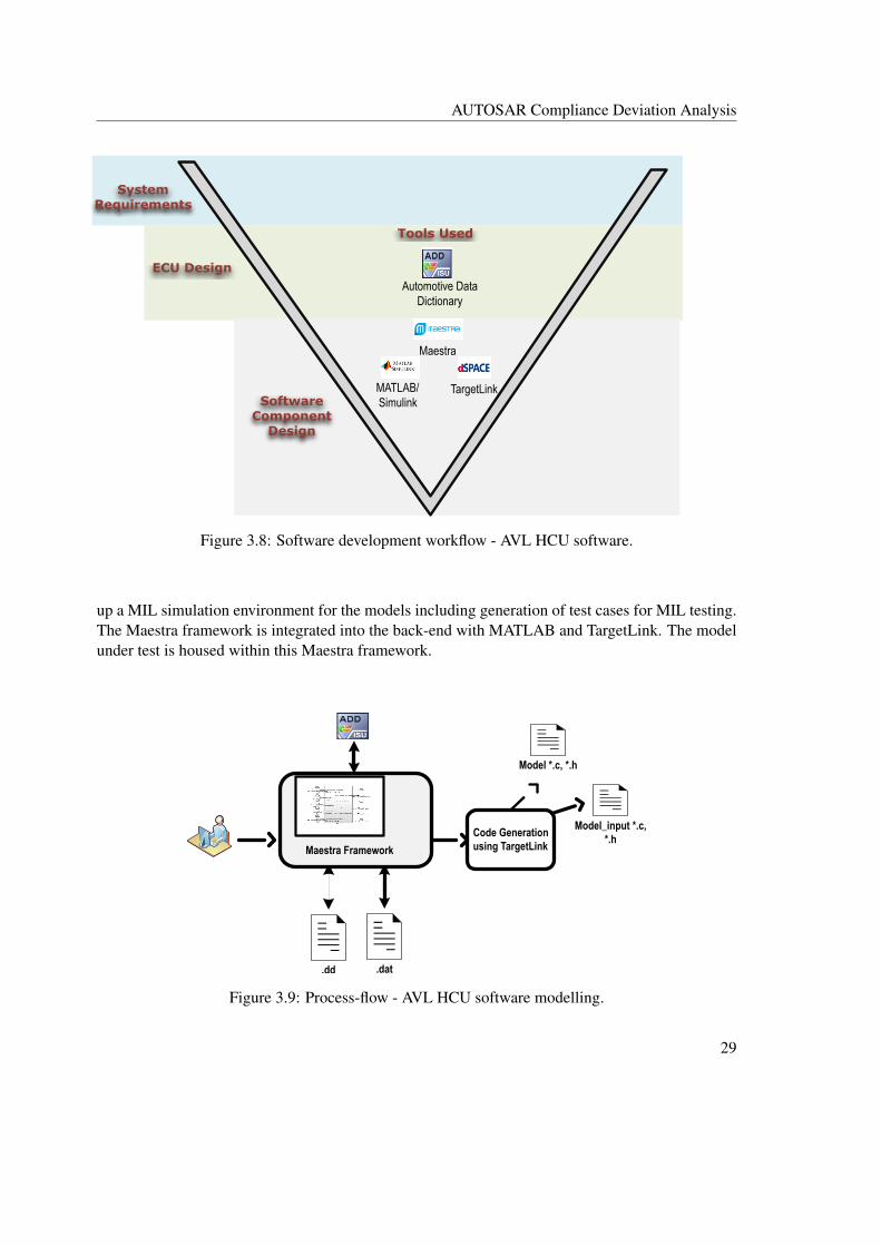
Figure 3.8: Software development workflow - AVL HCU software.
up a MIL simulation environment for the models including generation of test cases for MIL testing.The Maestra framework is integrated into the back-end with MATLAB and TargetLink. The modelunder test is housed within this Maestra framework.
.dd .dat
Model *.c, *.h
Model_input *.c, *.h
Code Generation using TargetLinkMaestra Framework
Figure 3.9: Process-flow - AVL HCU software modelling.
29

AUTOSAR Compliance Deviation Analysis
The AVL HCU software modelling process (Figure 3.9) involves the development of modelsin an integrated environment of Maestra framework, ADD, MATLAB, and TargetLink. The modeldata files specific to the MATLAB and TargetLink environment for denoting the signals and param-eters used in the SWC models are managed within the Maestra framework. As indicated earlier,these data files are maintained up-to-date with modifications in the ADD database, for example, anewly added parameter in the ADD database is automatically reflected in these data files. Besides,the TargetLink is used to generate SWC code files.
Model.mdl
Model_test.mdl
Model.AVLab
Library Link
Maestra
Interface
SWC Code Files
TargetLink Code Generation
Figure 3.10: Folder structure of the model and generated code in the AVL HCU software.
A fully developed SWC contains the following file entities: a model library, a test model, aMaestra session file and generated SWC code files. The relationship between these file entitiesis shown in Figure 3.10. The model algorithm is implemented using TargetLink blocks and isstored as a Simulink model library in .mdl format (e.g. Model.mdl). An additional test model (e.g.Model_test.mdl) file is created, which includes the interfaces to Maestra framework and links withthe model library mentioned above. This test model can be subjected to MIL testing. Additionally,the Model.AVLab, which is also known as the Maestra session file, represents the MIL simulationenvironment of the model. By loading the session file in Maestra, the test model can be housedwithin the MIL simulation environment.
3.4.2 Model Development Aspects in AUTOSAR Software Model
The software models in AUTOSAR environment involve port types and SWC types as mentionedin Section 3.3.2. A model development tool supporting AUTOSAR configuration provides the re-quired AUTOSAR template with the necessary port interfaces, wherein the model algorithm can beimplemented. Additionally, the tool also provides the necessary platform to configure the settingsof ports, runnable entities and RTE events. In the generated source code, the implemented modelalgorithm is coded as runnable entities.
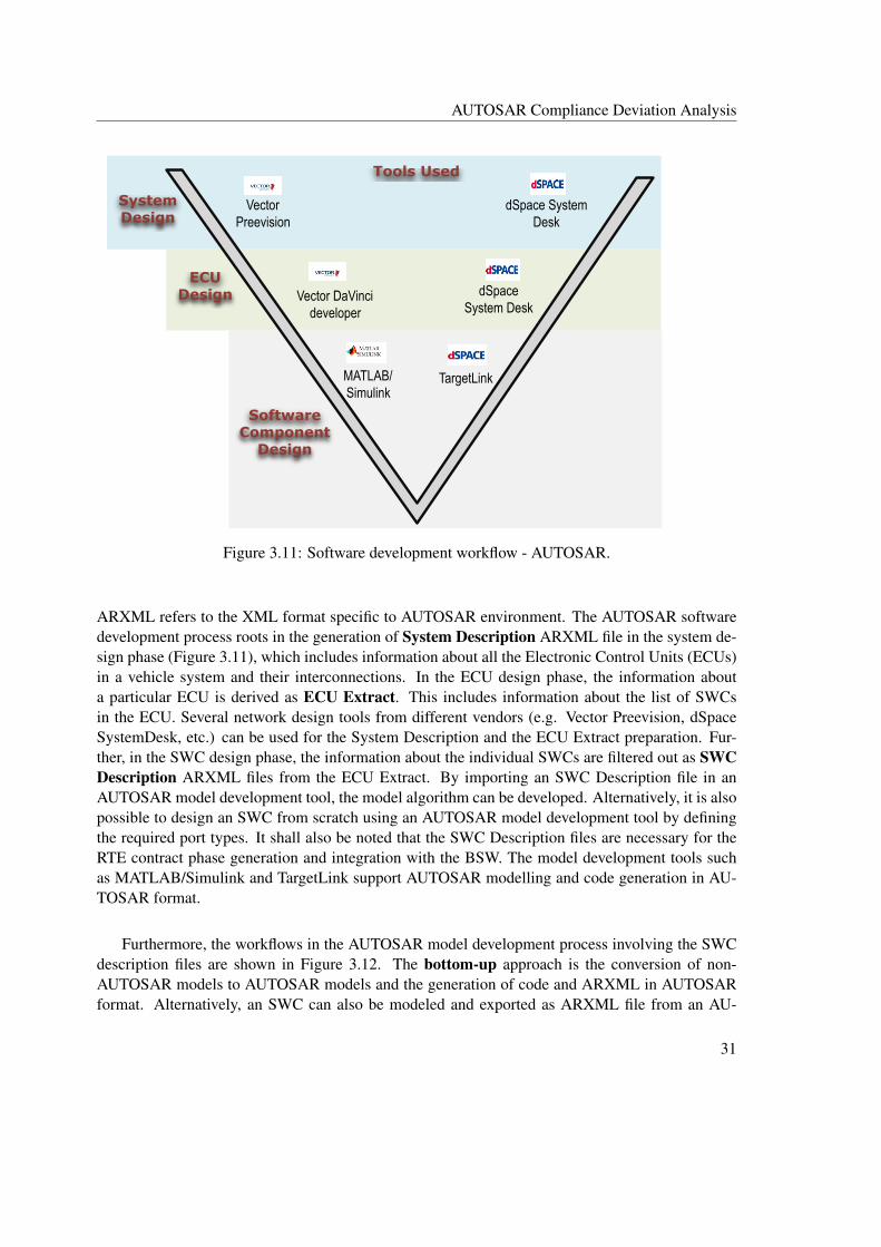
Another important feature in the AUTOSAR model development is the involvement of the AU-TOSAR Extensible Markup Language (ARXML) description files in every phase of development.
30
AUTOSAR Compliance Deviation Analysis
System Design
ECU Design
Software Component
Design
Tools Used
Vector Preevision
dSpace System Desk
Vector DaVinci developer
dSpace System Desk
MATLAB/Simulink
TargetLink
Figure 3.11: Software development workflow - AUTOSAR.
ARXML refers to the XML format specific to AUTOSAR environment. The AUTOSAR softwaredevelopment process roots in the generation of System Description ARXML file in the system de-sign phase (Figure 3.11), which includes information about all the Electronic Control Units (ECUs)in a vehicle system and their interconnections. In the ECU design phase, the information abouta particular ECU is derived as ECU Extract. This includes information about the list of SWCsin the ECU. Several network design tools from different vendors (e.g. Vector Preevision, dSpaceSystemDesk, etc.) can be used for the System Description and the ECU Extract preparation. Fur-ther, in the SWC design phase, the information about the individual SWCs are filtered out as SWCDescription ARXML files from the ECU Extract. By importing an SWC Description file in anAUTOSAR model development tool, the model algorithm can be developed. Alternatively, it is alsopossible to design an SWC from scratch using an AUTOSAR model development tool by definingthe required port types. It shall also be noted that the SWC Description files are necessary for theRTE contract phase generation and integration with the BSW. The model development tools suchas MATLAB/Simulink and TargetLink support AUTOSAR modelling and code generation in AU-TOSAR format.
Furthermore, the workflows in the AUTOSAR model development process involving the SWCdescription files are shown in Figure 3.12. The bottom-up approach is the conversion of non-AUTOSAR models to AUTOSAR models and the generation of code and ARXML in AUTOSARformat. Alternatively, an SWC can also be modeled and exported as ARXML file from an AU-
31

AUTOSAR Compliance Deviation Analysis
.ARXML
.ARXML
AUTOSAR SWC Design Tool
SWC Description File
SWC Description File
AUTOSAR Model Development Tool
Export
ARXMLImport/Update
Import/UpdateExport
ARXML
Non-AUTOSAR Models
Bottom-up Workflow
Top-down Workflow
Figure 3.12: Workflows in AUTOSAR model development. Adapted from [30].
TOSAR design tool. This ARXML can then be ported into a model development tool to developthe model algorithm and generate model code respectively. This type of workflow is referred toas a top-down approach. Additionally, there is also round-tripping approach, wherein it is alsopossible to port back the SWC description file into the AUTOSAR design tool in case of any modi-fications (e.g. addition of an extra sender/receiver port) and update the model algorithm [29].
While converting a non-AUTOSAR model to AUTOSAR model, one must carefully ensure thatthe correct port interfaces and SWC types (Section 3.3.2) are mapped to the input and output portsof the non-AUTOSAR model. For example, the ports requiring NVRAM access must be configuredas NV port types. Daehyun et al. [5] additionally mention that during the conversion processthe ASW functionality of legacy software must be distributed among the AUTOSAR SWC types.Therefore, the model implementation involving sensor or actuator functionality must be configuredas Sensor/Actuator SWC type; all the other application functionalities must be implemented inApplication SWC type. During model development in the AUTOSAR environment, the developersmust also be aware of the interaction rules among the various SWC types specified in the AUTOSARspecifications. An example of such interfacing rule is the ECU Abstraction component which caninteract only with the Sensor SWC type and not directly with the Application SWC type for I/Oaccess [8].
32
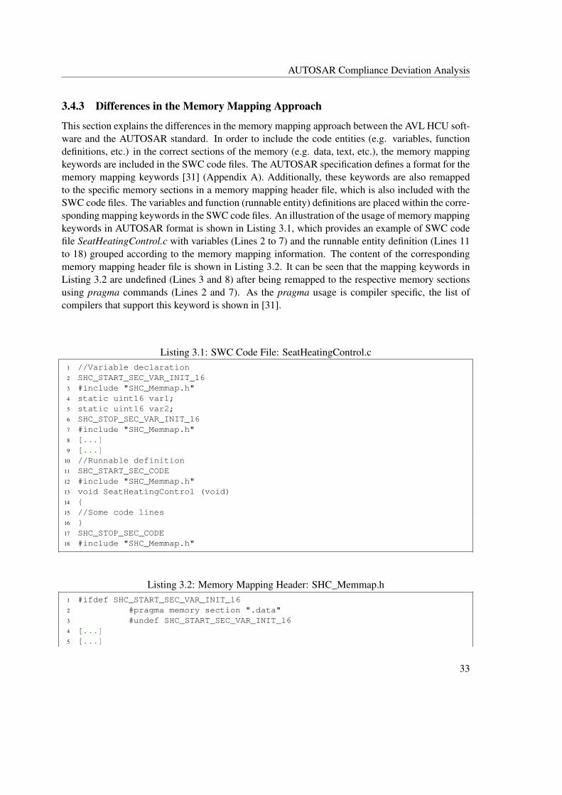
AUTOSAR Compliance Deviation Analysis
3.4.3 Differences in the Memory Mapping Approach
This section explains the differences in the memory mapping approach between the AVL HCU soft-ware and the AUTOSAR standard. In order to include the code entities (e.g. variables, functiondefinitions, etc.) in the correct sections of the memory (e.g. data, text, etc.), the memory mappingkeywords are included in the SWC code files. The AUTOSAR specification defines a format for thememory mapping keywords [31] (Appendix A). Additionally, these keywords are also remappedto the specific memory sections in a memory mapping header file, which is also included with theSWC code files. The variables and function (runnable entity) definitions are placed within the corre-sponding mapping keywords in the SWC code files. An illustration of the usage of memory mappingkeywords in AUTOSAR format is shown in Listing 3.1, which provides an example of SWC codefile SeatHeatingControl.c with variables (Lines 2 to 7) and the runnable entity definition (Lines 11to 18) grouped according to the memory mapping information. The content of the correspondingmemory mapping header file is shown in Listing 3.2. It can be seen that the mapping keywords inListing 3.2 are undefined (Lines 3 and 8) after being remapped to the respective memory sectionsusing pragma commands (Lines 2 and 7). As the pragma usage is compiler specific, the list ofcompilers that support this keyword is shown in [31].
Listing 3.1: SWC Code File: SeatHeatingControl.c1 //Variable declaration2 SHC_START_SEC_VAR_INIT_163 #include "SHC_Memmap.h"4 static uint16 var1;5 static uint16 var2;6 SHC_STOP_SEC_VAR_INIT_167 #include "SHC_Memmap.h"8 [...]9 [...]
10 //Runnable definition11 SHC_START_SEC_CODE12 #include "SHC_Memmap.h"13 void SeatHeatingControl (void)14 {15 //Some code lines16 }17 SHC_STOP_SEC_CODE18 #include "SHC_Memmap.h"
Listing 3.2: Memory Mapping Header: SHC_Memmap.h1 #ifdef SHC_START_SEC_VAR_INIT_162 #pragma memory section ".data"3 #undef SHC_START_SEC_VAR_INIT_164 [...]5 [...]
33

AUTOSAR Compliance Deviation Analysis
6 #ifdef SHC_START_SEC_CODE7 #pragma memory section ".text"8 #undef SHC_START_SEC_CODE9 #endif
The memory mapping keyword format of the AVL HCU software is defined by the BSW sup-plier (Appendix B). Unlike the AUTOSAR format, the SWC prefix (<COMPONENT_PREFIX>) isnot a part of the keyword format provided by the BSW supplier. Consequently, AVL can only adoptthe same keyword format (from the BSW supplier) generically for all the SWCs present in the HCUsoftware system, without differentiating the format for SWC-specific usage. However, in order toavoid the above scenario and to make the keyword format more distinct for SWC-specific usage,the mapping keywords have been remapped by AVL from supplier defined format to another formatwith the SWC prefix. A look at the memory mapping header file (Listing 3.3) used in the AVL HCUsoftware provides an understanding of the above statement. Lines 1 and 4 in Listing 3.3 representthe keywords redefined by AVL with the SWC component prefix. These are also the mapping key-words used in the SWC code files. Lines 3 and 6 represent the format provided by the BSW supplier.
Besides, there are no major differences in the process of memory mapping and memory handlingexcept for some naming conventions in the mapping keyword format, which are summarized inTable 3.3.
Listing 3.3: Memory Mapping Header used in AVL HCU Software: Memmap.h1 #elif defined AHM_START_SEC_CODE_10MS2 #undef AHM_START_SEC_CODE_10MS3 #define ASW1_OEM_START_SEC_DEFAULT_CODE4 #elif defined AHM_STOP_SEC_CODE_10MS5 #undef AHM_STOP_SEC_CODE_10MS6 #define ASW1_OEM_STOP_SEC_DEFAULT_CODE
Category Used in AVL HCU Software Specified by AUTOSAR Standard
File Name Memmap.h <Component>_memmap.h,wherein <Component> denotesthe module abbreviation of theSWC.
SWC Module Ab-breviation Prefix
<COMPONENT_PREFIX> is notincluded in the mapping keywordformat provided by the BSW sup-plier; however, it is used in the key-words remapped by AVL.
<COMPONENT_PREFIX> isa part of the memory mappingkeywords.
Variable Align-ment Postfixes
8, 16, 32, UNSPECIFIED 8, 16, 32, PTR, UNSPECIFIED
34
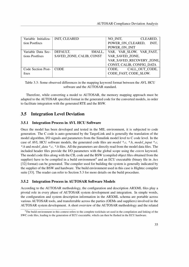
AUTOSAR Compliance Deviation Analysis
Variable Initializa-tion Postfixes
INIT, CLEARED NO_INIT, CLEARED,POWER_ON_CLEARED, INIT,POWER_ON_INIT
Variable Data Sec-tions Postfixes
DEFAULT, SMALL,SAVED_ZONE, CALIB, CONST
VAR, VAR_SLOW, VAR_FAST,VAR_SAVED_ZONE,VAR_SAVED_RECOVERY_ZONE,CONST, CALIB, CONFIG_DATA
Code Section Post-fixes
CODE CODE, CALL_OUT_CODE,CODE_FAST, CODE_SLOW.
Table 3.3: Some observed differences in the mapping keyword format between the AVL HCUsoftware and the AUTOSAR standard.
Therefore, while converting a model to AUTOSAR, the memory mapping approach must beadapted to the AUTOSAR specified format in the generated code for the converted models, in orderto facilitate integration with the generated RTE and the BSW.
3.5 Integration Level Deviation
3.5.1 Integration Process in AVL HCU Software
Once the model has been developed and tested in the MIL environment, it is subjected to codegeneration. The C code is auto-generated by the TargetLink and is generally the translation of themodel algorithm, I/O signals and parameters from the Simulink model level to C code level. In thecase of AVL HCU software models, the generated code files are model *.c, *.h, model_input *.c,*.h and model_data *.c, *.h files. All the parameters are directly read from the model data files. Theincluded header files provide the I/O parameters with the global scope using the extern keyword.The model code files along with the CIL code and the BSW (compiled object files obtained from thesupplier) have to be compiled in a build environment4 and an ECU executable (binary file in .hex[32] format) can be generated. The compiler used for building the system is generally indicated bythe supplier of the BSW and hardware. The build environment used in this case is Hightec compilersuite [33]. The reader can refer to Section 5.3 for more details on the build procedure.
3.5.2 Integration Process in AUTOSAR Software Models
According to the AUTOSAR methodology, the configuration and description ARXML files play apivotal role in every phase of AUTOSAR system development and integration. In simple words,the configuration and system description information in the ARXML schema are portable acrossvarious AUTOSAR tools, and transferrable across the parties (OEMs and suppliers) involved in theAUTOSAR system development. A short overview of the AUTOSAR methodology and the related
4The build environment in this context refers to the complete toolchain set used in the compilation and linking of theSWC code files, leading to the generation of ECU executable, which can then be flashed in the ECU hardware.
35
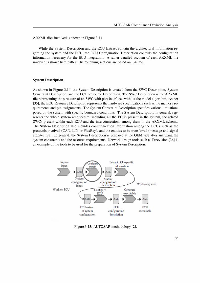
AUTOSAR Compliance Deviation Analysis
ARXML files involved is shown in Figure 3.13.
While the System Description and the ECU Extract contain the architectural information re-garding the system and the ECU, the ECU Configuration Description contains the configurationinformation necessary for the ECU integration. A rather detailed account of each ARXML fileinvolved is shown hereinafter. The following sections are based on [34, 35].
System Description
As shown in Figure 3.14, the System Description is created from the SWC Description, SystemConstraint Description, and the ECU Resource Description. The SWC Description is the ARXMLfile representing the structure of an SWC with port interfaces without the model algorithm. As per[35], the ECU Resource Description represents the hardware specifications such as the memory re-quirements and pin assignments. The System Constraint Description specifies various limitationsposed on the system with specific boundary conditions. The System Description, in general, rep-resents the whole system architecture, including all the ECUs present in the system, the relatedSWCs present within each ECU and the interconnections among them in the ARXML schema.The System Description also includes communication information among the ECUs such as theprotocols involved (CAN, LIN or FlexRay), and the entities to be transferred (message and signalarchitecture). In general, the System Description is prepared at the OEM side after analyzing thesystem constraints and the resource requirements. Network design tools such as Preevision [36] isan example of the tools to be used for the preparation of System Description.
Figure 3.13: AUTOSAR methodology [2].
36
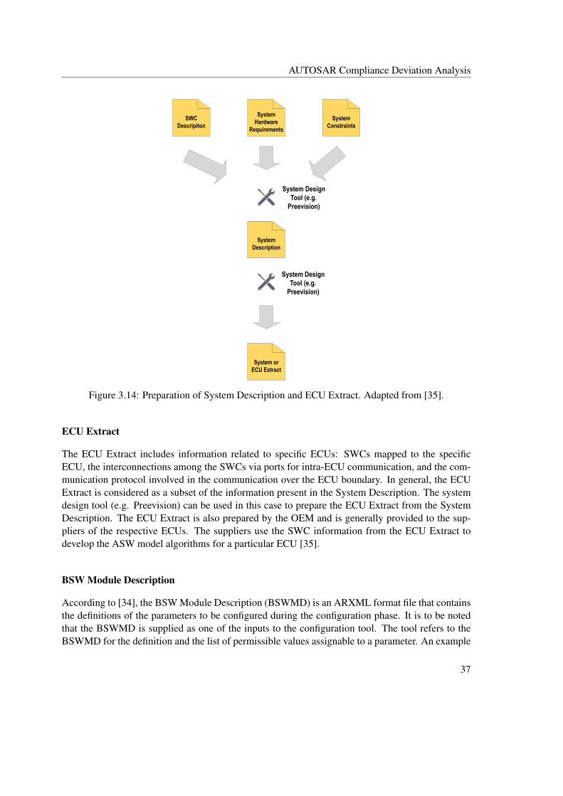
AUTOSAR Compliance Deviation Analysis
System Hardware
Requirements
System Constraints
SWC Descripiton
System Description
System or ECU Extract
System Design Tool (e.g.
Preevision)
System Design Tool (e.g.
Preevision)
Figure 3.14: Preparation of System Description and ECU Extract. Adapted from [35].
ECU Extract
The ECU Extract includes information related to specific ECUs: SWCs mapped to the specificECU, the interconnections among the SWCs via ports for intra-ECU communication, and the com-munication protocol involved in the communication over the ECU boundary. In general, the ECUExtract is considered as a subset of the information present in the System Description. The systemdesign tool (e.g. Preevision) can be used in this case to prepare the ECU Extract from the SystemDescription. The ECU Extract is also prepared by the OEM and is generally provided to the sup-pliers of the respective ECUs. The suppliers use the SWC information from the ECU Extract todevelop the ASW model algorithms for a particular ECU [35].
BSW Module Description
According to [34], the BSW Module Description (BSWMD) is an ARXML format file that containsthe definitions of the parameters to be configured during the configuration phase. It is to be notedthat the BSWMD is supplied as one of the inputs to the configuration tool. The tool refers to theBSWMD for the definition and the list of permissible values assignable to a parameter. An example
37
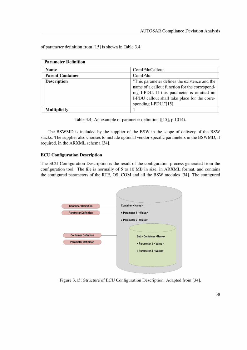
AUTOSAR Compliance Deviation Analysis
of parameter definition from [15] is shown in Table 3.4.
Parameter Definition
Name ComIPduCalloutParent Container ComIPdu.Description "This parameter defines the existence and the
name of a callout function for the correspond-ing I-PDU. If this parameter is omitted noI-PDU callout shall take place for the corre-sponding I-PDU."[15]
Multiplicity 1
Table 3.4: An example of parameter definition ([15], p.1014).
The BSWMD is included by the supplier of the BSW in the scope of delivery of the BSWstacks. The supplier also chooses to include optional vendor-specific parameters in the BSWMD, ifrequired, in the ARXML schema [34].
ECU Configuration Description
The ECU Configuration Description is the result of the configuration process generated from theconfiguration tool. The file is normally of 5 to 10 MB in size, in ARXML format, and containsthe configured parameters of the RTE, OS, COM and all the BSW modules [34]. The configured
Container <Name>
��Parameter 1 <Value> ��Parameter 2 <Value>
Sub - Container <Name>
��Parameter 3 <Value>
��Parameter 4 <Value>
Container Definition
Parameter Definition
Container Definition
Parameter Definition
Figure 3.15: Structure of ECU Configuration Description. Adapted from [34].
38
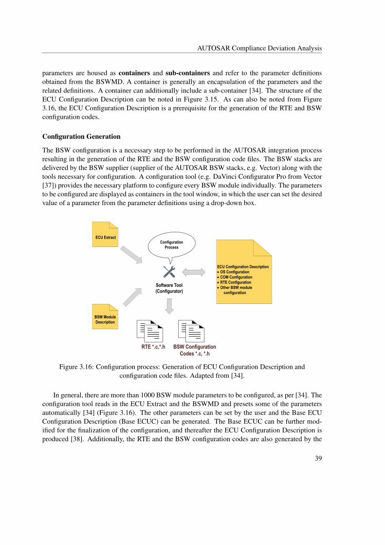
AUTOSAR Compliance Deviation Analysis
parameters are housed as containers and sub-containers and refer to the parameter definitionsobtained from the BSWMD. A container is generally an encapsulation of the parameters and therelated definitions. A container can additionally include a sub-container [34]. The structure of theECU Configuration Description can be noted in Figure 3.15. As can also be noted from Figure3.16, the ECU Configuration Description is a prerequisite for the generation of the RTE and BSWconfiguration codes.
Configuration Generation
The BSW configuration is a necessary step to be performed in the AUTOSAR integration processresulting in the generation of the RTE and the BSW configuration code files. The BSW stacks aredelivered by the BSW supplier (supplier of the AUTOSAR BSW stacks, e.g. Vector) along with thetools necessary for configuration. A configuration tool (e.g. DaVinci Configurator Pro from Vector[37]) provides the necessary platform to configure every BSW module individually. The parametersto be configured are displayed as containers in the tool window, in which the user can set the desiredvalue of a parameter from the parameter definitions using a drop-down box.
ECU Extract
BSW Module Description
Software Tool (Configurator)
ECU Configuration Description��OS Configuration��COM Configuration��RTE Configuration��Other BSW module
configuration
RTE *.c,*.h BSW Configuration Codes *.c, *.h
Configuration Process
Figure 3.16: Configuration process: Generation of ECU Configuration Description andconfiguration code files. Adapted from [34].
In general, there are more than 1000 BSW module parameters to be configured, as per [34]. Theconfiguration tool reads in the ECU Extract and the BSWMD and presets some of the parametersautomatically [34] (Figure 3.16). The other parameters can be set by the user and the Base ECUConfiguration Description (Base ECUC) can be generated. The Base ECUC can be further mod-ified for the finalization of the configuration, and thereafter the ECU Configuration Description isproduced [38]. Additionally, the RTE and the BSW configuration codes are also generated by the
39

AUTOSAR Compliance Deviation Analysis
BSW Stacks
BSWMD
BSW + Task bodies
Implementation of CILApplication SW Models and Code
Generation
Integration and Generation of ECU Executable
ECU Extract
Application SW Models and Code Generation
Configuration and RTE Generation
Integration and Generation of ECU Executable
Supplier AVL OEM
AVL Methdology AUTOSAR Methodology
Figure 3.17: Comparison of software development methodology between AVL HCU software andAUTOSAR software models.
configuration tool from the ECU Configuration Description.
It is also noteworthy mentioning that the BSW module parameters can fall into different config-uration classes: pre-compile time, link-time and post-build, which determine the time in whichthe BSW parameters are finalized in the build process [39]. The pre-compile time and the link-timeparameters are fixed during the compilation and the linking phase of the BSW module code5 re-spectively, while the post-build parameters are set only during the ECU boot phase [39]. The readercan additionally refer to [40] for more information on configuration classes.
Integration and Executable Generation
The next step involves the integration and executable generation. The BSW configuration codefiles generated by the configuration tools along with the BSW module code files, RTE code files,and SWC code files are compiled and built in a build environment. Once the system is built suc-cessfully, the ECU executable can be generated as a binary file (.hex) which can be flashed in theECU hardware. Regina in [39] additionally mentions that the handling of BSW parameters in thebuild process varies with different configuration class types introduced previously. For example, thepre-compile time parameters have to be compiled along with the BSW module code files, while thepost-build and link-time parameters have to be supplied as compiled object files for linking with theBSW module code in the generation of ECU executable [39].
5The BSW module code in this context refers to the BSW static source delivered by an AUTOSAR BSW supplier(e.g. MICROSAR from Vector [41])
40

AUTOSAR Compliance Deviation Analysis
3.6 Comparison of Development Methodology
This section summarizes the current software development methodology of AVL and the steps to befollowed if AUTOSAR methodology is to be adopted by AVL. As per Figure 3.17, in the develop-ment methodology of AVL HCU software, the supplier implements the BSW and the task bodies,whereas the ASW modelling, code generation and the implementation of CIL layer are handledby AVL. If the AUTOSAR approach is to be followed, the supplier needs to deliver the config-urable BSW stacks along with the BSWMD and toolchains necessary for the BSW configurationand integration. In AUTOSAR case, AVL shall be responsible for the ASW model development,BSW configuration, RTE generation as well as the integration with BSW. The customer OEM mayadditionally supply the ECU Extract with the SWC information necessary for the ASW model de-velopment.
41

AUTOSAR Compliance Deviation Analysis
42
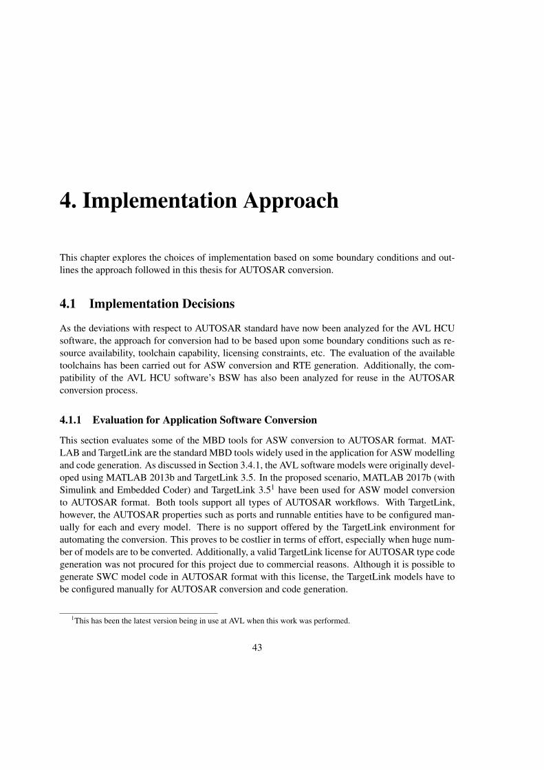
4. Implementation Approach
This chapter explores the choices of implementation based on some boundary conditions and out-lines the approach followed in this thesis for AUTOSAR conversion.
4.1 Implementation Decisions
As the deviations with respect to AUTOSAR standard have now been analyzed for the AVL HCUsoftware, the approach for conversion had to be based upon some boundary conditions such as re-source availability, toolchain capability, licensing constraints, etc. The evaluation of the availabletoolchains has been carried out for ASW conversion and RTE generation. Additionally, the com-patibility of the AVL HCU software’s BSW has also been analyzed for reuse in the AUTOSARconversion process.
4.1.1 Evaluation for Application Software Conversion
This section evaluates some of the MBD tools for ASW conversion to AUTOSAR format. MAT-LAB and TargetLink are the standard MBD tools widely used in the application for ASW modellingand code generation. As discussed in Section 3.4.1, the AVL software models were originally devel-oped using MATLAB 2013b and TargetLink 3.5. In the proposed scenario, MATLAB 2017b (withSimulink and Embedded Coder) and TargetLink 3.51 have been used for ASW model conversionto AUTOSAR format. Both tools support all types of AUTOSAR workflows. With TargetLink,however, the AUTOSAR properties such as ports and runnable entities have to be configured man-ually for each and every model. There is no support offered by the TargetLink environment forautomating the conversion. This proves to be costlier in terms of effort, especially when huge num-ber of models are to be converted. Additionally, a valid TargetLink license for AUTOSAR type codegeneration was not procured for this project due to commercial reasons. Although it is possible togenerate SWC model code in AUTOSAR format with this license, the TargetLink models have tobe configured manually for AUTOSAR conversion and code generation.
1This has been the latest version being in use at AVL when this work was performed.
43

Implementation Approach
In comparison, the MATLAB/Simulink environment offers programmatic features with dedi-cated AUTOSAR specific APIs for automating the model conversion to AUTOSAR format [45].In addition, the Embedded Coder environment can generate code in AUTOSAR format with theadd-on ’AUTOSAR support package’ installed. The programmatic features are quite convenientwhen the conversion has to be handled automatically using MATLAB scripts. In converting thelegacy application to AUTOSAR, Daehyun et al. [5] have used MATLAB for migrating the ASWmodels of an interior lighting system to AUTOSAR format. However, there is no clear indicationof automation being applied in this work. James at al. [6] additionally recommend MATLAB for asimpler and quicker way of automating the ASW conversion and have employed MATLAB scriptsto convert a body control application to AUTOSAR format. The authors in [6] have used wrap-pers to convert the normal Simulink port types to AUTOSAR port types. The usage of wrapperblocks is however not required with the recent versions of MATLAB (with the ’AUTOSAR supportpackage’) that support AUTOSAR type model development. The authors in [6] also stress upon theneed for automation when a large number of ASW models are involved. We preferred MATLABto TargetLink in this thesis due to its support for automation and a large number of about 40 ASWmodels of HCU software system were subjected for AUTOSAR conversion.
4.1.2 Evaluation of Basic Software for Integration
It was decided to reuse the original BSW of the AVL HCU software for AUTOSAR conversionsince AUTOSAR specific BSW stacks and the related configuration tools were not procured forthis project due to commercial reasons. As mentioned in Section 2.2.4, the BSW structure used inAVL HCU software is not AUTOSAR compliant. Nevertheless, the BSW possesses the requiredfeatures supporting the integration with an AUTOSAR ASW. For example, the task bodies providedby the BSW supplier can be used to schedule ASW runnable entities, and the supplier-specificAPI interfaces from the BSW can still be integrated with the AUTOSAR ASW via an interfacingmiddleware.
4.1.3 Evaluation for Run Time Environment Generation
According to AUTOSAR, the RTE layer contains function definitions for resolving the SWC portcommunication and task bodies for scheduling the runnable entities (Section 2.1.2). It can be notedthat the BSW architecture of the AVL HCU software, which is to be reused for AUTOSAR conver-sion, already contains some of the features of the RTE, such as the task bodies (Figure 2.9) providedby the BSW supplier, which can schedule the ASW runnable entities. Thus, the aim is to generatethe RTE portion involving only ASW communication. The RTE generation capability has beenevaluated using DaVinci developer2. DaVinci developer [42] is a Vector proprietary tool primarilyused for ECU and SWC design. As we found out that the tool can only generate RTE contractphase header files with the code generation option, we decided to implement an RTE generator en-gine in MATLAB based on [7], which can generate the RTE function definitions involving ASWcommunication.
2We could evaluate only DaVinci developer since it was procured by AVL as an evaluation package for a customerproject. Other RTE generator tools were not procured due to commercial reasons.
44

Implementation Approach
4.2 Conversion Approach towards AUTOSAR Compliance
Figure 4.1 illustrates the conversion approach used in this thesis. The Application SWCs and thecommunication features among them are already converted to AUTOSAR format (with the RTEportion generated). The original non-AUTOSAR BSW of the AVL HCU software has been reusedfor integration. Additionally, since the CIL contains functionalities related to CAN signal checksand other signal mappings (Section 2.2.3), replacing the layer can be costlier in terms of manualmodifications needed in the code level. Hence we have decided to retain the CIL layer. The in-terfaces between the CIL and the BSW have not been modified; therefore these interfaces are notAUTOSAR conformed. The proposed conversion approach can still promise ICC1 AUTOSARconformance level, although fullest AUTOSAR ICC3 conformance is not possible. The ICC1 con-formance category states that the BSW along with the RTE implementation is proprietary, which canbe considered as a single black-box unit, and that only the SWC communication and the interfaceswith this black-box unit need to be AUTOSAR conformed. In the proposed approach (Figure 4.1),
SWC1 SWC2 SWC3
APPLICATION SOFTWARE
CIL
COM Service
NVRAMSystem
ServicesDiag
Service
Task Bodies
BASIC SOFTWARE
Static Global Variables
Variable Mapping with CIL
API Interfaces provided by supplier
to Application
Signal Mappings, UDS Callbacks and other manually implementable Functions
RTE portion for ASW communication
RTE portion implemented for Application SWC communication
Application SWCs converted
to AUTOSAR format
Considered a single cluster
(black-box entity)
ICC1 standardized ASW and the interfacing
portion
Figure 4.1: AUTOSAR conversion approach used in the thesis.
45

Implementation Approach
the RTE portion along with the CIL and the BSW can be considered as a single unit, interfaced withthe Application SWCs converted to AUTOSAR format. Daehyun et al. [5] additionally mentionthat if a non-AUTOSAR BSW has to be reused for AUTOSAR migration, only an AUTOSAR con-formance of ICC1 or ICC2 can be achieved and that only a new AUTOSAR specific BSW moduleshave to be used if implementation conformance of ICC3 is targeted. Thus the proposed AUTOSARconversion approach cannot meet ICC3 conformance requirements however, it can conform to ICC1category. Some of the features in the proposed concept which are not conformed according to ICC3requirements are summarized in Table 4.1.
Category Proposed AUTOSAR ConversionConcept
AUTOSAR ICC3 Requirements
I/O Signal Access The presence of I/O Hardware Ab-straction layer is not explicit in theBSW implementation. I/O signalsare accessed via the supplier definedAPI interfaces from the BSW androuted via the CIL to the ASW.
I/O Hardware Abstraction SWCtype in the BSW is used for I/O sig-nal access (Section 3.3.2).
BSW-RTE Inter-faces
Only the RTE portion involving Ap-plication SWC communication isAUTOSAR conformed. The inter-faces to the BSW are not conformwith AUTOSAR due to the pres-ence of the CIL layer.
The RTE-BSW interaction involvesstandardized API calls (Section3.3.2).
Scheduling ofRunnable entities
The task bodies used in the runnablescheduling are part of BSW imple-mentation from the supplier. TheRTE events are however not part ofBSW implementation and are notused in the scheduling of runnableentities. The scheduling approach isthe same as that used in the originalAVL HCU software (Section 3.3.3)since the CIL and the BSW imple-mentations were retained.
The task bodies are configured inthe RTE configuration step and gen-erated as part of the RTE genera-tion. The invocation of runnableentities may also depend on RTEevents (Section 3.3.3).
DevelopmentMethodology
AUTOSAR methodology has notbeen followed. The configurationstep of the BSW is not needed sincethe BSW is pre-configured by thesupplier.
The development process mustfollow the AUTOSAR proposedmethodology from scratch. Theconfiguration of the RTE and theBSW is a necessary step in softwareintegration.
Table 4.1: Some of the features which are not AUTOSAR conformed as per ICC3 requirements inthe proposed conversion approach.
46

5. Implementation
In Chapter 3, the software deviations from the AUTOSAR standard have been analyzed, and inChapter 4, the concept for AUTOSAR conversion has been put forth. This chapter focuses on theimplementation part to incorporate the HCU software with AUTOSAR features.
5.1 Model Conversion to AUTOSAR
This section deals with the conversion of ASW models of AVL HCU software to AUTOSAR format.MATLAB provides a licensed ’AUTOSAR support package’ for model development in AUTOSARenvironment and also for the conversion of non-AUTOSAR models to AUTOSAR format. MAT-LAB also ensures that the model conversion to AUTOSAR format can be handled programmaticallywithout the need for manual configuration of each model. As analyzed in Section 4.1.1, the pro-grammatic feature has been preferred in this thesis, since a software system of HCU comprisingof about 40 models are to be converted to AUTOSAR format. A cascade of MATLAB scripts wasused to automate the model conversion and code generation in AUTOSAR format. In a nutshell, themodel conversion process involves the following steps:
1. Removal of TargetLink properties.
2. Generation of new model libraries with ._Lib suffix.
3. Extraction of AVL software models from the Maestra framework.
4. Applying AUTOSAR conversion.
Figure 5.1 illustrates the steps involved in the ASW conversion process and the by-products aftereach step. MATLAB scripts were developed to handle each of the above-mentioned steps. TheTargetLink models indicated in the first step of Figure 5.1 are the state of the art developmentmodels of the non-AUTOSAR AVL HCU software. The sections hereinafter provide a detaileddescription of the scripts involved and the results observed after each conversion step. The scriptfiles are shown as excerpts in the form of listings.
47

Implementation
Deenhancing TargetLink properties
TargetLink models
Pure Simulink models
Generation of new model libraries
Extraction from Maestra framework
Models with new libraries
Applying AUTOSAR conversion
Standalone models
AUTOSAR format code and ARXML
Figure 5.1: ASW conversion flow.
5.1.1 Removal of TargetLink Properties
The original AVL HCU software models were developed using TargetLink blocks. In order tohandle the models in the MATLAB/Embedded Coder environment, the TargetLink property hasto be removed, which is generally the replacement of TargetLink blocks in the model with theequivalent Simulink blocks. This step is necessary since the code generation for the AUTOSARconverted models are to be handled in the Embedded Coder environment. The MATLAB scriptDeEnhanceTlProp.m was developed for the purpose of removing the TargetLink properties. Figure5.2 provides a general understanding of the program flow.
Code and Explanation
The script is invoked as a function call from the MATLAB command window. MATLAB 2013bhas been used in this case, since it is supported by TargetLink 3.5 using which the AVL software
48

Implementation
Start
Search and collect the list of all the test models in
MdlTestListRaw
Load model, disable library links and save the
model
Clear TargetLink properties
End
Save the model in .slx format and close
Prepare logs
End of the list MdlTestListRaw?
Yes
No
Figure 5.2: Program flow: DeEnhanceTlProp.m
models have been developed. The project path1 (Line 1 of Listing 5.1) of the AVL software modelsis provided as an argument to the function. The part of the code in Listing 5.1 searches all the modelssaved with the suffix _Test.mdl. As indicated in Section 3.4.1, the test models are the ones that linkwith the model libraries and are loadable within the Maestra framework for MIL simulation. Thefunction subdir in Line 4 of Listing 5.1 is used to collect the list of all the test models present in theproject directory.
Listing 5.1: DeEnhanceTlProp.m - Collection of test model list.1 function str = DeEnhanceTLProp(FolderPath)2 [...]3 %% Search for all the test models4 MdlTestListRaw = subdir([Dereflink.Projectpath '\*_Test.mdl']);5 [...]
1The folder path to the AVL HCU software project directory which contains all the ASW model implementations.
49

Implementation
Listing 5.2: DeEnhanceTlProp.m - Saving the models by disabling the library links.1 [...]2 %% Break links and save the model3 save_system(TestMdlNameName, [TestMdlPath '\' TestMdlNameName], 'BreakLinks')4 load_system(TestMdlNameName);5 open_system(TestMdlNameName);6 [...]
The script in the next step goes through the list of all the test models and saves the model bybreaking the library links (Line 3 of Listing 5.2). This step is performed to unlock the library linksto the model libraries, so that the <Model_Test>.mdl can be edited.
Listing 5.3: DeEnhanceTlProp.m - Clearing TargetLink properties.1 [...]2 %% Applying deenhancement of TargetLink properties3 [options, msg] = tl_clear_system('system', TestMdlNameName);4 [...]
In the next step, the deenhancement of TargetLink properties is applied. The tl_clear_sytem(Appendix C) is the MATLAB API provided by the TargetLink for the removal of TargetLink blocksfrom the system. The API also returns logs of the function in the form of structure, which can beused to verify the results of deenhancement from TargetLink blocks. The usage is shown in Line 3of Listing 5.3. The logs are also stored as excel files. After the application of deenhancement, themodel is saved in .slx format and the function continues with the next iteration in the list of models.
Results
B. After Deenhancement (Simulink Blocks)
A. Before Deenhancement (TargetLink Blocks)
Figure 5.3: Model block properties before and after deenhancement.
All the test models were removed from TargetLink properties. Figure 5.3 compares the modelproperties before and after deenhancement. For illustrative purpose, only a subset of model blocks(AND, NOT and relational operator blocks) from the model implementation is considered in Figure5.3. Figure 5.3A shows the TargetLink blocks before deenhancement, while the same blocks after
50

Implementation
deenhancement are replaced with the equivalent Simulink blocks in Figure 5.3B. An excel log fileis also generated for each model after the deenhancement has been applied.
5.1.2 Generation of New Model Libraries
Once the TargetLink features are removed from the test models, new model libraries have to be gen-erated with respect to the newly replaced Simulink blocks. The new model library can be generatedby opening the Maestra session file (.AVLab file) of a deenhanced test model and selecting the op-tion ’Create new library’, which creates a new library Model_Lib in the .slx format. As this processis to be accomplished for the entire software system, MATLAB script CreateLibrariesBatch.m wasdeveloped to expedite the library creation for all the available test models. This script has been ex-ecuted in MATLAB 2017b so that the newly generated model libraries are generated in .slx formatby default. The process flow of the script is shown in Figure 5.4.
Collect the list of all .AVLab files
AVLabListRaw
Generate libraries with _Lib
End
End of the list AVLabListRaw ?
Yes
No
Start
Figure 5.4: Program flow: CreateLibrariesBatch.m.
Code and Explanation
The project directory, which now contains the deenhanced test models from the previous step, ispassed as an argument to the function CreateLibrariesBatch.m. As per Figure 5.4 and Listing 5.4,in the first step, the function CreateLibrariesBatch.m searches and collects the list of all the Maestrasession (.AVLab) files present in the project directory (Line 2 of Listing 5.4).
51
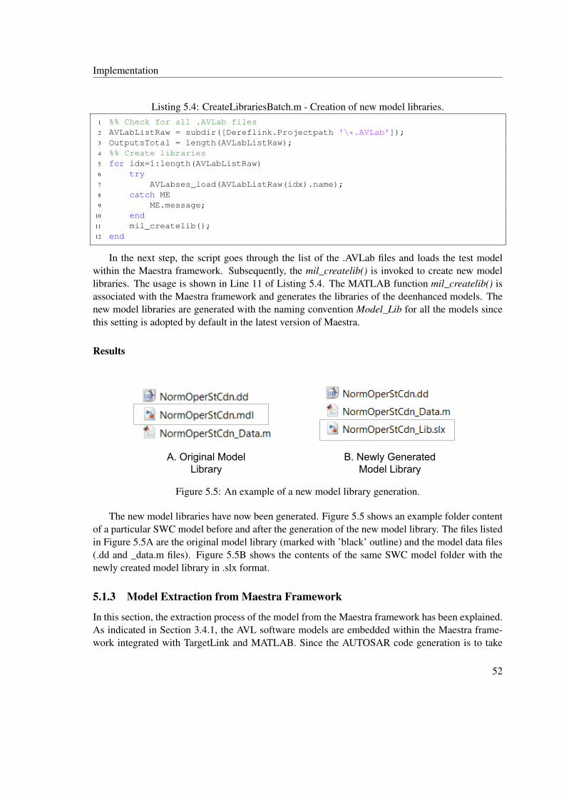
Implementation
Listing 5.4: CreateLibrariesBatch.m - Creation of new model libraries.1 %% Check for all .AVLab files2 AVLabListRaw = subdir([Dereflink.Projectpath '\*.AVLab']);3 OutputsTotal = length(AVLabListRaw);4 %% Create libraries5 for idx=1:length(AVLabListRaw)6 try7 AVLabses_load(AVLabListRaw(idx).name);8 catch ME9 ME.message;
10 end11 mil_createlib();12 end
In the next step, the script goes through the list of the .AVLab files and loads the test modelwithin the Maestra framework. Subsequently, the mil_createlib() is invoked to create new modellibraries. The usage is shown in Line 11 of Listing 5.4. The MATLAB function mil_createlib() isassociated with the Maestra framework and generates the libraries of the deenhanced models. Thenew model libraries are generated with the naming convention Model_Lib for all the models sincethis setting is adopted by default in the latest version of Maestra.
Results
A. Original Model Library
B. Newly Generated Model Library
Figure 5.5: An example of a new model library generation.
The new model libraries have now been generated. Figure 5.5 shows an example folder contentof a particular SWC model before and after the generation of the new model library. The files listedin Figure 5.5A are the original model library (marked with ’black’ outline) and the model data files(.dd and _data.m files). Figure 5.5B shows the contents of the same SWC model folder with thenewly created model library in .slx format.
5.1.3 Model Extraction from Maestra Framework
In this section, the extraction process of the model from the Maestra framework has been explained.As indicated in Section 3.4.1, the AVL software models are embedded within the Maestra frame-work integrated with TargetLink and MATLAB. Since the AUTOSAR code generation is to take
52
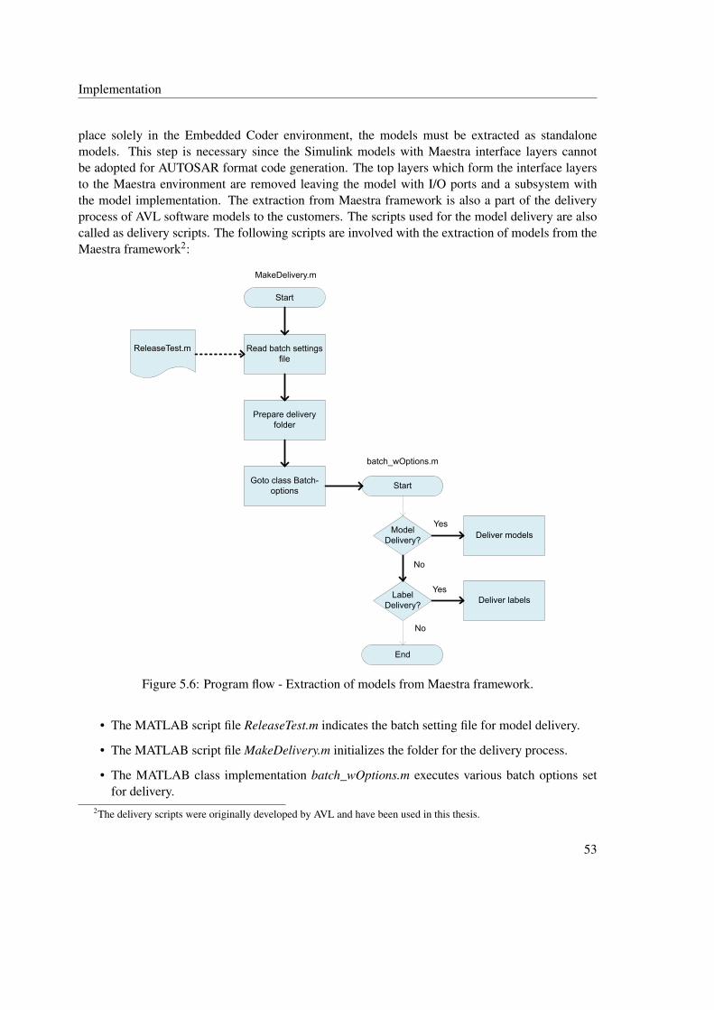
Implementation
place solely in the Embedded Coder environment, the models must be extracted as standalonemodels. This step is necessary since the Simulink models with Maestra interface layers cannotbe adopted for AUTOSAR format code generation. The top layers which form the interface layersto the Maestra environment are removed leaving the model with I/O ports and a subsystem withthe model implementation. The extraction from Maestra framework is also a part of the deliveryprocess of AVL software models to the customers. The scripts used for the model delivery are alsocalled as delivery scripts. The following scripts are involved with the extraction of models from theMaestra framework2:
Start
Read batch settings file
Goto class Batch-options
Prepare delivery folder
Start
Model Delivery?
Label Delivery?
End
Deliver models
Deliver labels
ReleaseTest.m
MakeDelivery.m
batch_wOptions.m
Yes
Yes
No
No
Figure 5.6: Program flow - Extraction of models from Maestra framework.
• The MATLAB script file ReleaseTest.m indicates the batch setting file for model delivery.
• The MATLAB script file MakeDelivery.m initializes the folder for the delivery process.
• The MATLAB class implementation batch_wOptions.m executes various batch options setfor delivery.
2The delivery scripts were originally developed by AVL and have been used in this thesis.
53

Implementation
The code files are explained in excerpts in the following section.
Code and Explanation
Figure 5.6 provides an understanding of the program flow of the delivery scripts used for modelextraction from the Maestra framework. The script file ReleaseTest.m provides the batch settingsfor the options to be executed by the class file batch_wOptions.m. An excerpt from ReleaseTest.mis shown in Listing 5.5 showing various options for the settings to be set for the delivery process.The setting file ReleaseTest.m is instantiated in the constructor of the class batch_wOptions.m.
Listing 5.5: ReleaseTest.m - Batch options for the model delivery process.1 %Setting for data file delivery2 settings.EnaCalDelivery = true;3 [...]4 %Setting for calibration file delivery5 settings.EnaDataDelivery = true;6 [...]7 %Setting for model delivery8 settings.EnaModelDelivery = true;9 [...]
10 %Setting for label delivery11 settings.EnaLabelDelivery = 'full';
Listing 5.5 indicates that the batch settings for the delivery of the model, data and calibration files areset to true (Lines 2,5 and 8). The setting of label delivery to ’full’ (Line 11) delivers the signal andparameter list to be used in the model as .xlsx files. For the models to be delivered, it is necessary toenable these options in the delivery process. The ReleaseTest.m is also stored in the project directoryunder the folder named PrjCfg. Listing 5.6 includes the option setting in ReleaseTest.m where thepaths of .AVLab session files of the models to be delivered are placed (Lines 2 to 5). These arealso the models to be removed from the Maestra framework. Additionally, the library path is alsoincluded which includes some Simulink libraries to be used in the models (Lines 8 to 10).
Listing 5.6: ReleaseTest.m - Maestra session file (.AVLab) paths of the various models to bedelivered.
1 %.AVLab session file paths2 settings.AvlabSessionFiles = {...3 'ASW\ObsrEStorg\ObsrHvbat\ObsrHvbat.AVLab'4 'ASW\LatCtlr\TracTqLimn\TracTqLimn.AVLab'5 };6 [...]7 %Library paths8 settings.AdditionalFiles = {...9 'ASW\Lib\ProjLib\ProjectLib.slx'
10 };
54
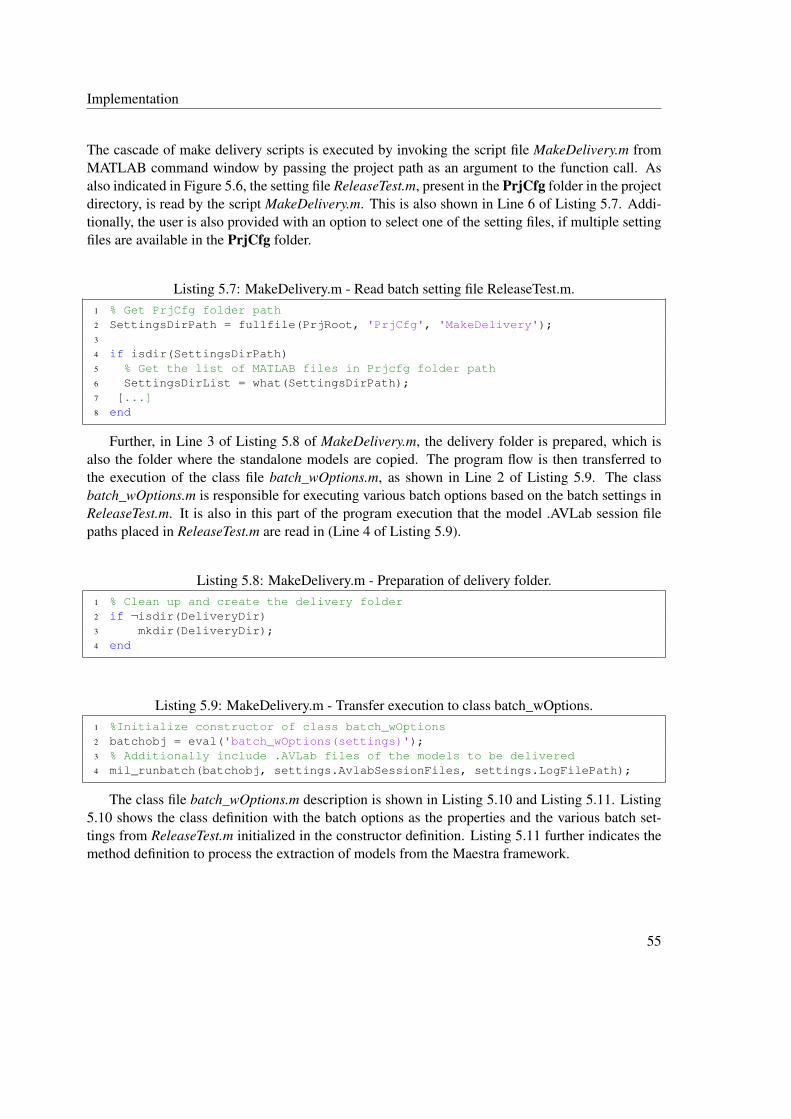
Implementation
The cascade of make delivery scripts is executed by invoking the script file MakeDelivery.m fromMATLAB command window by passing the project path as an argument to the function call. Asalso indicated in Figure 5.6, the setting file ReleaseTest.m, present in the PrjCfg folder in the projectdirectory, is read by the script MakeDelivery.m. This is also shown in Line 6 of Listing 5.7. Addi-tionally, the user is also provided with an option to select one of the setting files, if multiple settingfiles are available in the PrjCfg folder.
Listing 5.7: MakeDelivery.m - Read batch setting file ReleaseTest.m.1 % Get PrjCfg folder path2 SettingsDirPath = fullfile(PrjRoot, 'PrjCfg', 'MakeDelivery');3
4 if isdir(SettingsDirPath)5 % Get the list of MATLAB files in Prjcfg folder path6 SettingsDirList = what(SettingsDirPath);7 [...]8 end
Further, in Line 3 of Listing 5.8 of MakeDelivery.m, the delivery folder is prepared, which isalso the folder where the standalone models are copied. The program flow is then transferred tothe execution of the class file batch_wOptions.m, as shown in Line 2 of Listing 5.9. The classbatch_wOptions.m is responsible for executing various batch options based on the batch settings inReleaseTest.m. It is also in this part of the program execution that the model .AVLab session filepaths placed in ReleaseTest.m are read in (Line 4 of Listing 5.9).
Listing 5.8: MakeDelivery.m - Preparation of delivery folder.1 % Clean up and create the delivery folder2 if ¬isdir(DeliveryDir)3 mkdir(DeliveryDir);4 end
Listing 5.9: MakeDelivery.m - Transfer execution to class batch_wOptions.1 %Initialize constructor of class batch_wOptions2 batchobj = eval('batch_wOptions(settings)');3 % Additionally include .AVLab files of the models to be delivered4 mil_runbatch(batchobj, settings.AvlabSessionFiles, settings.LogFilePath);
The class file batch_wOptions.m description is shown in Listing 5.10 and Listing 5.11. Listing5.10 shows the class definition with the batch options as the properties and the various batch set-tings from ReleaseTest.m initialized in the constructor definition. Listing 5.11 further indicates themethod definition to process the extraction of models from the Maestra framework.
55

Implementation
Listing 5.10: batch_wOptions.m - Class body and constructor initialization.1 classdef batch_wOptions < batch_template2 % Class body for the execution of delivery batch options3 % - Creates a delivery model4 % - Zips all delivery models to a delivery folder5
6 properties7 % data and calibration8 EnaCalDelivery9 EnaDataDelivery
10 EnaLabelDelivery11 [...]12 % models13 EnaModelDelivery14
15 methods16 %Constructor initialization17 function obj = batch_wOptions(PreSettings)18 % data and calibration19 obj.EnaCalDelivery = PreSettings.EnaCalDelivery;20 obj.EnaDataDelivery = PreSettings.EnaDataDelivery;21 obj.EnaLabelDelivery = PreSettings.EnaLabelDelivery;22
23 % models24 obj.EnaModelDelivery = PreSettings.EnaModelDelivery;
Listing 5.11: batch_wOptions.m - Method definition for model extraction from Maestra.1 %% Deliver Model as IOLayer Model or Library only2 if obj.EnaModelDelivery3 if obj.EnaModelDelivery == true4 % Create the delivery model5 [suc(end+1), msg{end+1}, ¬] = Delivery.createIOLayerMdl(ses, ...
obj.dsSearchDepth);6 msg{end} = sprintf('Model\n%s\n', msg{end});7 end
The function createIOLayerMdl() (Line 5 of Listing 5.11) is associated with the Maestra frameworkfor processing the .AVLab session files as standalone models with single I/O layer removing theinterface layers to Maestra.
Results
The models were extracted from the Maestra framework and the delivered SWC entities such asthe extracted models, the model libraries, the data files, and the labels were copied to the deliveryfolder. An illustration of the extracted model is shown in Figure 5.73. It can be seen that the Maestrainterface layer forms the top layer in the original AVL HCU software models (Figure 5.7A). The
3The original model files could not be used for a clear representation. Hence image illustration has been used here.
56

Implementation
deenhanced Simulink model is shown as an ’orange’ block in Figure 5.7. After the extraction pro-cess, the Maestra interface layers are removed and the model subsystem is extracted as a standalonemodel, as shown in Figure 5.7B. This standalone model can be subjected to AUTOSAR conversionin the next step. An example of the top layer model subsystem without the Maestra interface layersas seen in Simulink window is additionally shown in Figure 5.8. The text in Figure 5.8 representvarious model I/O signals.
Simulink model
Maestra Interface Layer
A. Models housed within Maestra framework (Before Delivery)
B. Standalone Models (After Delivery)
Simulink model
Figure 5.7: Models before and after extraction from Maestra framework.
A label file in .xlsx format is delivered for each model which provides information about thelabels (I/O signals and parameters) used in the model implementation. The information containedin the label file of a particular model is summarized in Table 5.1.
Label Fields Description
Name Indicates the name of the signals/parameters used in the model.Description Provides a short description of the parameters/signals used in the model.Type Indicates the type of the labels used in the model (e.g. Online for signals;
Parameter for parameters).Classification Indicates the scope of the signals/parameters used in the model (e.g.
Local for local signals/parameters; Input/Output for I/O signals/param-eters).
Datatype Indicates the data type of the parameters/signals used in the model (e.g.uint8).
57

Implementation
Value Range Indicates the range of values in the hexadecimal notation for parameter-s/signals used in the model (e.g. 0 to FF for signal/parameters with typeuint8).
Memory Range Indicates memory range in the hexadecimal notation for parameters/sig-nals used in the model (e.g. 0 to 255 for signal/parameters with typeuint8).
Source Component Indicates the source of the signals/parameters used in the model.
Table 5.1: Summary of label fields.
Figure 5.8: An example model subsystem in the topmost layer of the delivered model with the I/Oports.
In addition, the model parameters/signals in the data files are converted from the AVLmpt4 pack-age to the native Simulink mpt5 package during the delivery process. A ’package’ is specific toMATLAB/Simulink environment and can contain multiple class definitions with various storage-class attributes to qualify the model parameters and signals [43, 44]. The storage-class attributes
4AVLmpt defines various storage-class specifiers for signals/parameters handled within the Maestra framework.5mpt package is used to qualify signals and parameters in the Simulink environment.
58

Implementation
gain importance only in the code generation and determine how a particular signal/parameter mustbe handled in the generated code [43]. For example, a parameter can be qualified to be handled as acalibration parameter or as a system constant in the generated code. The Simulink mpt is the defaultpackage used for the models in the Simulink environment. The AVLmpt package is defined by AVLfor the HCU software models developed within the Maestra environment. When the models areremoved from the Maestra framework, the reference to the AVLmpt package is also lost.
5.1.4 Applying AUTOSAR Conversion
As the models have been extracted from the Maestra framework, the model conversion to AU-TOSAR can be applied in the next step. The script PrepareAUTOSARDelivery.m was developedfor applying AUTOSAR conversion to models and to generate code in AUTOSAR format. TheAUTOSAR preparation for AVL software models has been handled in the Embedded Coder envi-ronment based on [45]. The general flow of the script PrepareAUTOSARDelivery.m is shown inFigure 5.9.
Code and Explanation
The delivery folder path, where the models and the artifacts extracted from the Maestra frameworkare stored, is provided as an argument to the MATLAB function call PrepareAUTOSARDelivery.m.The script flow can be explained in the following steps, in accordance with Figure 5.9.
1. The delivery folder contains the SWC models and the corresponding libraries delivered fromthe previous model extraction step. Each model library contains the SWC model implemen-tation. In Step 1, the list of all the SWCs available in the delivery folder is prepared (Line2 of Listing 5.12). The script then loops through the list and prepares a new model file<Model>_AR.slx (Line 5 of Listing 5.12) for each SWC item in the list by creating a copyof the model implementation from the corresponding model library. The MATLAB func-tions shown in Lines 8 to 11 of Listing 5.12 have been used to add the subsystem block andestablish connections among the ports.
Listing 5.12: PrepareAUTOSARDelivery.m - Preparation of SWC list and <Model>_ARfile.
1 % Collection of the list of model libraries2 SWCListRaw = subdir([PrepASDelCfg.ProjectPath '\*_Lib.slx']);3 [...]4 %Preparation of new model file <Model>_AR5 copyfile(SWCMainMdlPath, SWCAUTOSARMdlPath);6 [...]7 %Addition of model implementation in <Model>_AR from the model library8 add_block(SWCLibPath,SubSysPath);9 SubSysPos = get_param(SubSysPath,'Position');
10 ConnectInPrts(SubSysPath);11 ConnectOutPrts(SubSysPath);12 [...]
59

Implementation
Start
End
Configure AUTOSAR properties and save <Model>_AR in .slx
format
Generate data files in AUTOSAR.mpt format
Generate code and ARXML
Prepare logs
Collect the list of SWCs in the delivery folder in
SWCListRaw
End of the list SWCListRaw ?
Create a copy of the model implementation from library to a new
model file <Model>_AR
Prepare data store blocks for local signals in the top level of the new model file
YesNo
Figure 5.9: Program flow - PrepareAUTOSARDelivery.m.
Additionally, the data store memory blocks are also created in this step for handling all thelocal signals. The data store blocks act as internal variables to handle the local signals withinthe Simulink environment. A list of local signals available is collected in DSMList and thecode excerpt from Line 3 in Listing 5.13 shows the addition of the data store memory blocksfor the list of local signals contained in DSMList.
60

Implementation
Listing 5.13: PrepareAUTOSARDelivery.m - Preparation of data store memory blocks.1 % Preparation of data store memory blocks2 for i=1:length(DSMList)3 hBlock = add_block('simulink/Signal Routing/Data Store ...
Memory',[SWCAUTOSARMdlName '/' DSMList{i}]);4 end
The above discussed part of the script PrepareAUTOSARDelivery.m involving the preparationof the models for AUTOSAR conversion including the data store blocks was developed byAVL for a customer project and the same concept has been used in this thesis.
2. The next step is the configuration of AUTOSAR properties for the <Model>_AR.slx createdin the above step. In order to include AUTOSAR properties for a model, the following entitieshave been configured in the script:
• Configuration of Ports: As the I/O communication in the AVL HCU software modelsinvolves static global variables, the Simulink I/O ports have been converted to ImplicitSender/Receiver ports.
• Configuration of Runnables: The types of runnable entities configured are Runnable_initfor initialization and Runnable_step (periodic runnable entity) for functional implemen-tation. The Runnable_step has been renamed with the corresponding SWC model prefix.
The API commands for AUTOSAR conversion described in ([45], p.4-211) have been usedfor programmatically configuring the AUTOSAR properties. The model, in this case, hasbeen configured as a default AUTOSAR component. Line 2 in Listing 5.14 indicates theMATLAB API autosar.api.create (Appendix D) to create a default AUTOSAR component.In Line 3 of Listing 5.14, the AUTOSAR properties of the model are extracted to a MATLABobject autosarProps, which can later be used to edit the runnable or port properties of themodel. The runnable namings for Runnable_init (Lines 7 to 8) and Runnable_step (Lines 11to 12) have been configured using autosarProps as shown in Listing 5.14.
Listing 5.14: PrepareAUTOSARDelivery.m - Configuration of AUTOSAR properties.1 %% Configuring default AUTOSAR properties2 autosar.api.create(SWCAUTOSARMdlName,'default');3 autosarProps = autosar.api.getAUTOSARProperties(SWCAUTOSARMdlName);4
5 %% Configure runnable namings6 %%Init Runnable7 set(autosarProps,runnables{1},'symbol',PortFormatFound_Init{1});8 set(autosarProps,runnables{1},'Name',PortFormatFound_Init{1});9
10 %%Step runnable11 set(autosarProps,runnables{2},'symbol',PortFormatFound_Schedule{1});12 set(autosarProps,runnables{2},'Name',PortFormatFound_Schedule{1});
61

Implementation
3. In step 3, the signals and parameters data objects in the delivered data files have been con-verted from the native Simulink mpt to the AUTOSAR package [45]. The AUTOSAR packagehas been defined in MATLAB in order to handle the signals and parameters for AUTOSARmodel development in the Simulink environment. The AUTOSAR package has its own set ofcustom storage class attributes to qualify the parameters and signals for AUTOSAR formatcode generation. The parameters, for example, can be set to act as local calibration parame-ters, global calibration parameters, or as system constants in the generated code depending onthe CustomStorageClass setting. Table 5.2 summarizes various CustomStorageClass settingsdefined by AUTOSAR package and have been used in the script for various parameters andsignal types.
Parameter Types CustomStorageClass Setting
Local calibration parameters CustomStorageClass = ’InternalCalPrm’Global calibration parameters CustomStorageClass = ’CalPrm’System constants CustomStorageClass = ’SystemConstant’Local signals CustomStorageClass = ’perInstanceMemory’Signals requiring NVRAM access CustomStorageClass = ’perInstanceMemory’
CustomAttributes.needsNVRAMAccess =True
Table 5.2: Various CustomStorageClass setting for AUTOSAR class package.
The part of the script PrepareAUTOSARDelivery.m involving the conversion of model param-eters to AUTOSAR package was developed by AVL for a customer project and the same hasbeen used in this thesis.
4. As there were only limited number of signals requiring NVRAM access in the HCU soft-ware system, these signals have been configured manually from the MATLAB workspaceby setting the CustomStorageClass to ’PerInstanceMemory’ and selecting the option need-sNVRAMAccess to ’True’ (Table 5.2) before the code generation.
5. Once the AUTOSAR features have been set-up for the model, the model C code in AUTOSARformat can be generated by Embedded Coder. To do so, a set of code generation settings hasbeen configured in the script for the Embedded Coder environment as shown in Listing 5.15.
Listing 5.15: PrepareAUTOSARDelivery.m - AUTOSAR format code generation setting.1 %% Set code generation setting2 cs = getActiveConfigSet(SWCAUTOSARMdlName);3 switchTarget(cs,'autosar.tlc',[]);4 % Start code generation5 rtwbuild(SWCAUTOSARMdlName);
62
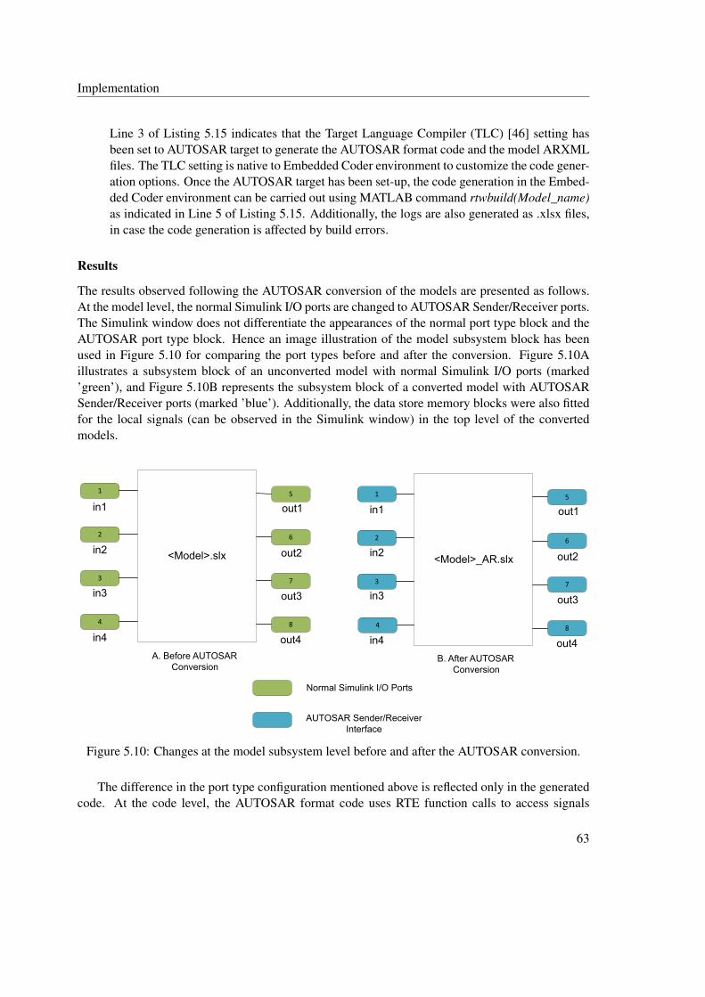
Implementation
Line 3 of Listing 5.15 indicates that the Target Language Compiler (TLC) [46] setting hasbeen set to AUTOSAR target to generate the AUTOSAR format code and the model ARXMLfiles. The TLC setting is native to Embedded Coder environment to customize the code gener-ation options. Once the AUTOSAR target has been set-up, the code generation in the Embed-ded Coder environment can be carried out using MATLAB command rtwbuild(Model_name)as indicated in Line 5 of Listing 5.15. Additionally, the logs are also generated as .xlsx files,in case the code generation is affected by build errors.
Results
The results observed following the AUTOSAR conversion of the models are presented as follows.At the model level, the normal Simulink I/O ports are changed to AUTOSAR Sender/Receiver ports.The Simulink window does not differentiate the appearances of the normal port type block and theAUTOSAR port type block. Hence an image illustration of the model subsystem block has beenused in Figure 5.10 for comparing the port types before and after the conversion. Figure 5.10Aillustrates a subsystem block of an unconverted model with normal Simulink I/O ports (marked’green’), and Figure 5.10B represents the subsystem block of a converted model with AUTOSARSender/Receiver ports (marked ’blue’). Additionally, the data store memory blocks were also fittedfor the local signals (can be observed in the Simulink window) in the top level of the convertedmodels.
<Model>.slx
1
2
3
4
5
6
7
8
in1
in2
in3
in4
out1
out2
out3
out4
<Model>_AR.slx
1
2
3
4
5
6
7
8
in1
in2
in3
in4
out1
out2
out3
out4A. Before AUTOSAR
ConversionB. After AUTOSAR
Conversion
Normal Simulink I/O Ports
AUTOSAR Sender/Receiver Interface
Figure 5.10: Changes at the model subsystem level before and after the AUTOSAR conversion.
The difference in the port type configuration mentioned above is reflected only in the generatedcode. At the code level, the AUTOSAR format code uses RTE function calls to access signals
63
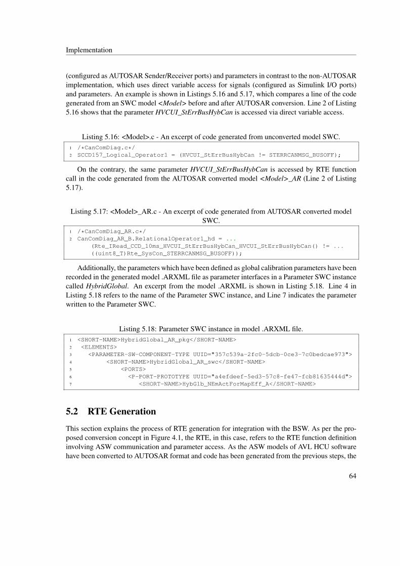
Implementation
(configured as AUTOSAR Sender/Receiver ports) and parameters in contrast to the non-AUTOSARimplementation, which uses direct variable access for signals (configured as Simulink I/O ports)and parameters. An example is shown in Listings 5.16 and 5.17, which compares a line of the codegenerated from an SWC model <Model> before and after AUTOSAR conversion. Line 2 of Listing5.16 shows that the parameter HVCUI_StErrBusHybCan is accessed via direct variable access.
Listing 5.16: <Model>.c - An excerpt of code generated from unconverted model SWC.1 /*CanComDiag.c*/2 SCCD157_Logical_Operator1 = (HVCUI_StErrBusHybCan != STERRCANMSG_BUSOFF);
On the contrary, the same parameter HVCUI_StErrBusHybCan is accessed by RTE functioncall in the code generated from the AUTOSAR converted model <Model>_AR (Line 2 of Listing5.17).
Listing 5.17: <Model>_AR.c - An excerpt of code generated from AUTOSAR converted modelSWC.
1 /*CanComDiag_AR.c*/2 CanComDiag_AR_B.RelationalOperator1_hd = ...
(Rte_IRead_CCD_10ms_HVCUI_StErrBusHybCan_HVCUI_StErrBusHybCan() != ...((uint8_T)Rte_SysCon_STERRCANMSG_BUSOFF));
Additionally, the parameters which have been defined as global calibration parameters have beenrecorded in the generated model .ARXML file as parameter interfaces in a Parameter SWC instancecalled HybridGlobal. An excerpt from the model .ARXML is shown in Listing 5.18. Line 4 inListing 5.18 refers to the name of the Parameter SWC instance, and Line 7 indicates the parameterwritten to the Parameter SWC.
Listing 5.18: Parameter SWC instance in model .ARXML file.1 <SHORT-NAME>HybridGlobal_AR_pkg</SHORT-NAME>2 <ELEMENTS>3 <PARAMETER-SW-COMPONENT-TYPE UUID="357c539a-2fc0-5dcb-0ce3-7c0bedcae973">4 <SHORT-NAME>HybridGlobal_AR_swc</SHORT-NAME>5 <PORTS>6 <P-PORT-PROTOTYPE UUID="a4efdeef-5ed3-57c8-fe47-fcb81635444d">7 <SHORT-NAME>HybGlb_NEmActForMapEff_A</SHORT-NAME>
5.2 RTE Generation
This section explains the process of RTE generation for integration with the BSW. As per the pro-posed conversion concept in Figure 4.1, the RTE, in this case, refers to the RTE function definitioninvolving ASW communication and parameter access. As the ASW models of AVL HCU softwarehave been converted to AUTOSAR format and code has been generated from the previous steps, the
64

Implementation
RTE Generator Script
Template files
Component ARXML
HybridGlobal_Data.cHybridGlobal_Data.h
RTE_<Component>.cRTE_<Component>.h
Figure 5.11: Structure of RTE generator.
next step is to generate the RTE portion. In this thesis, the RTE generation has been handled viaRTE generator implemented using MATLAB. The following section explains the implementationof RTE generator.
5.2.1 Implementation of RTE Generator
A design of RTE generator has already been proposed by Shiquan Piao et al. in [7]. Accordingto this work, an RTE generator shall contain an ARXML parser, which reads the contents of AU-TOSAR ARXML files; a generator engine, which generates the code based on template and dataobtained from the ARXML and; a template file, which describes a code structure to be used by thegenerator engine. The aforementioned model of RTE generator has been adopted for this thesis andstructured as shown in Figure 5.11. Additionally, the RTE generator has been implemented usingMATLAB M-Script and used to generate the RTE and HybridGlobal container code files as perFigure 5.11. The HybridGlobal container code files are generated as Parameter SWC instance anddenote the global calibration and measurement variables6 to be used by all the models in the HCUsoftware system.
A general process flow of the RTE generator script RTEGenerator.m is shown in Figure 5.12.The implementation is explained as follows.
Code and Explanation
1. In the first step (from Figure 5.12), the template files are read by the RTEGenerator.m. Asmentioned before, the template files provide a general structure for the RTE code text. A sepa-rate template file has been created as a text-file for Rte_<Component>.c, Rte_<Component>.h,
6The calibration parameters include single parameter values, 1D curve arrays and 2D map arrays.
65

Implementation
Start
Read template files
Read component ARXML
End
Template files
Prepare list for I/O ports; local and global
parameters; local signals; system constants
Prepare variable declaration, access
function definition and prototype text for I/O
ports, parameters and local signals
Perform file write operation into .c, .h code
files
Code files
Component ARXML
Figure 5.12: RTEGenerator.m - Process flow.
HybridGlobal_Data.c and HybridGlobal_Data.h. The template structure used for Rte_<Comp-onent>.c is shown in Listing 5.19 as an example. The template text is replaced by code textin the generated RTE files.
Listing 5.19: RTE code template.1 ##HEADER INCLUDE##2
3 ##CAL START SEC##4
5 ##PARAMETER DECLARATION##6
7 ##CAL STOP SEC##8
9 ##VAR START SEC##10
66

Implementation
11 ##SIGNAL VARIABLE DECLARATION##12
13 ##OUTPORT VARIABLE DECLARATION##14
15 ##VAR STOP SEC##16
17 ##CODE START SEC##18
19 ##PARAMETER ACCESS FUNCTION DEFINITION##20
21 ##READ FUNCTION DEFINITION##22
23 ##WRITE FUNCTION DEFINITION##24
25 ##SIGNAL FUNCTION DEFINITION##26
27 ##CODE STOP SEC##
2. In Step 2, the component ARXML files are read and the parsing of ARXML takes place.The information about an SWC including the port variables, calibration parameters, systemconstants, and signals are collected and prepared as lists. Listing 5.20 denotes the MATLABAPIs ([45], p. 6-63) used for parsing of component ARXML. Line 2 in Listing 5.20 showsthe import of component ARXML using API arxml.import (Appendix E). Additionally, thefind (Appendix F) API has been used (shown in Lines 5,8,11 and 14 of Listing 5.20) to extractinformation, such as the Application SWCs, Parameter SWCs, system constants and signallist present in the component ARXML.
Listing 5.20: RTEGenerator.m - Parsing of ARXML and collection of SWC entities.1 %% Import of ARXML components2 ar = arxml.importer(file)3
4 %% Application software component search5 aswcPath = find(ar,[],'AtomicComponent','PathType','FullyQualified');6
7 %% Get all system constant paths8 SysConsList = find(ar,[],'SystemConst','PathType','FullyQualified');9
10 %% Local Signals11 signal_list = find(ar,[],'ExclusiveArea','PathType','FullyQualified')12
13 %% Parameter software component search14 paramcomp = ...
find(ar,[],'ParameterComponent','PathType','FullyQualified');
67

Implementation
3. Once the list of port variables and parameters have been collected, the next step is to preparethe code text. The MATLAB API sprintf()7 has been used to create the code text, whichinvolves preparing the function definitions, prototypes, and variable declarations. The datatype and values of the parameters/variables are resolved from the corresponding componentdata files. An example of code text creation for RTE write functions Rte_IWrite_XXX() isshown in Listing 5.21.
Listing 5.21: RTEGenerator.m - Preparation of code text.1 %% Write Function Definition2 write_function_line = sprintf('void Rte_IWrite_%s_%s_%s(%s ...
data)\r\n',runnable_step_name,sportname,sportname,datatype_outport);3 write_function_line = sprintf('%s{\r\n',write_function_line);4 write_function_line = sprintf('%s %s = ...
data;\r\n',write_function_line, sportname);5 write_function_line = sprintf('%s}\r\n', write_function_line);6 outport_func_def_text = sprintf('%s%s\r\n', outport_func_def_text, ...
write_function_line);
4. In the final step, the template text is converted into the corresponding code text and written to*.c, *.h files. The MATLAB file-create and file-write functions fopen and fprintf have beenused in this case, as shown in Lines 2 and 3 of Listing 5.22. This step eventually generatesthe required files shown in Figure 5.11.
Listing 5.22: RTEGenerator.m - Code file creation.1 %RTE Source file creation2 RTE_c = fopen(code_file_name,'w');3 fprintf(RTE_c,'%s\r\n',RTE_code_text);4 fclose(RTE_c);
Results
The code files Rte_<Component>.c, Rte_<Component>.h, HybridGlobal_Data.c, and HybridGloba-l_Data.h were generated as a result. Excerpts from an RTE code file Rte_CTCa.c generated foran Application SWC CluTqCalc are discussed for illustration in Listings 5.23 and 5.24. TheRte_CTCa.c is generated based on the RTE code template file shown in Listing 5.19.
7The function sprintf() is used to store data as strings. The format of usage can be found in MATLAB Help Docu-mentation.
68
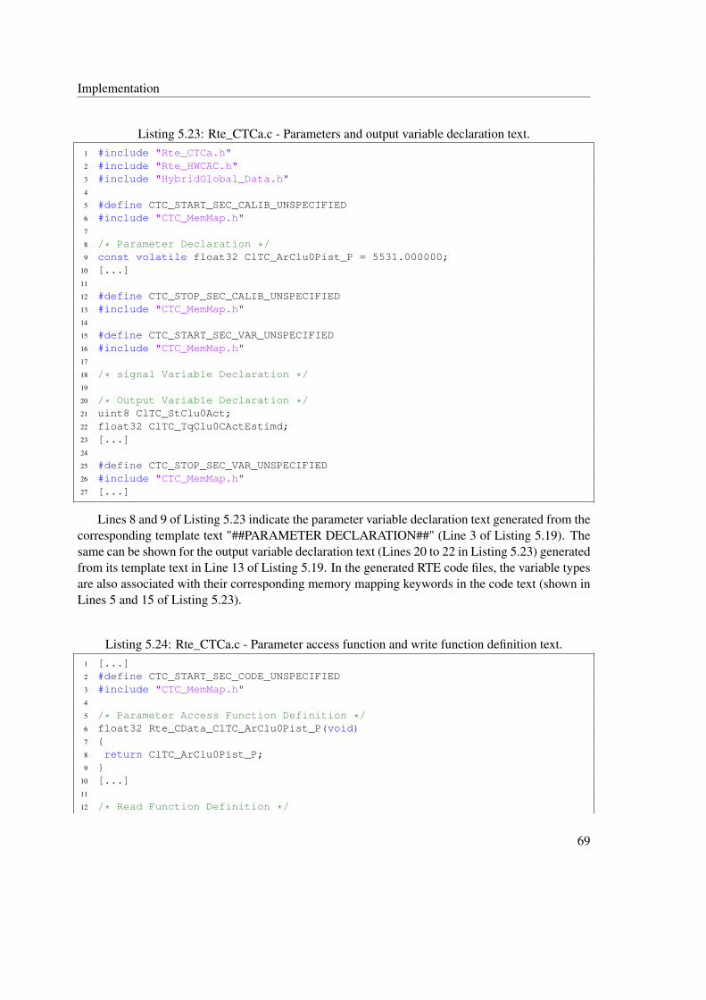
Implementation
Listing 5.23: Rte_CTCa.c - Parameters and output variable declaration text.1 #include "Rte_CTCa.h"2 #include "Rte_HWCAC.h"3 #include "HybridGlobal_Data.h"4
5 #define CTC_START_SEC_CALIB_UNSPECIFIED6 #include "CTC_MemMap.h"7
8 /* Parameter Declaration */9 const volatile float32 ClTC_ArClu0Pist_P = 5531.000000;
10 [...]11
12 #define CTC_STOP_SEC_CALIB_UNSPECIFIED13 #include "CTC_MemMap.h"14
15 #define CTC_START_SEC_VAR_UNSPECIFIED16 #include "CTC_MemMap.h"17
18 /* signal Variable Declaration */19
20 /* Output Variable Declaration */21 uint8 ClTC_StClu0Act;22 float32 ClTC_TqClu0CActEstimd;23 [...]24
25 #define CTC_STOP_SEC_VAR_UNSPECIFIED26 #include "CTC_MemMap.h"27 [...]
Lines 8 and 9 of Listing 5.23 indicate the parameter variable declaration text generated from thecorresponding template text "##PARAMETER DECLARATION##" (Line 3 of Listing 5.19). Thesame can be shown for the output variable declaration text (Lines 20 to 22 in Listing 5.23) generatedfrom its template text in Line 13 of Listing 5.19. In the generated RTE code files, the variable typesare also associated with their corresponding memory mapping keywords in the code text (shown inLines 5 and 15 of Listing 5.23).
Listing 5.24: Rte_CTCa.c - Parameter access function and write function definition text.1 [...]2 #define CTC_START_SEC_CODE_UNSPECIFIED3 #include "CTC_MemMap.h"4
5 /* Parameter Access Function Definition */6 float32 Rte_CData_ClTC_ArClu0Pist_P(void)7 {8 return ClTC_ArClu0Pist_P;9 }
10 [...]11
12 /* Read Function Definition */
69
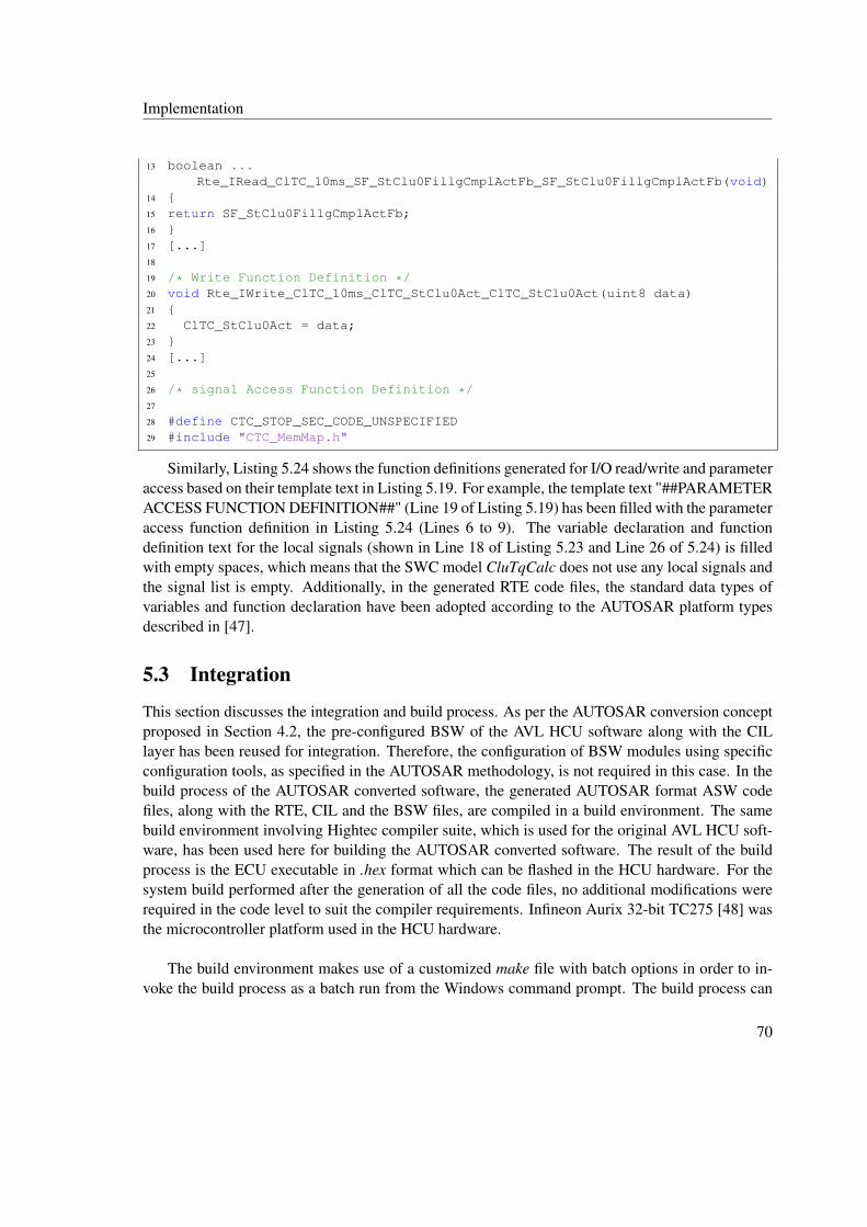
Implementation
13 boolean ...Rte_IRead_ClTC_10ms_SF_StClu0FillgCmplActFb_SF_StClu0FillgCmplActFb(void)
14 {15 return SF_StClu0FillgCmplActFb;16 }17 [...]18
19 /* Write Function Definition */20 void Rte_IWrite_ClTC_10ms_ClTC_StClu0Act_ClTC_StClu0Act(uint8 data)21 {22 ClTC_StClu0Act = data;23 }24 [...]25
26 /* signal Access Function Definition */27
28 #define CTC_STOP_SEC_CODE_UNSPECIFIED29 #include "CTC_MemMap.h"
Similarly, Listing 5.24 shows the function definitions generated for I/O read/write and parameteraccess based on their template text in Listing 5.19. For example, the template text "##PARAMETERACCESS FUNCTION DEFINITION##" (Line 19 of Listing 5.19) has been filled with the parameteraccess function definition in Listing 5.24 (Lines 6 to 9). The variable declaration and functiondefinition text for the local signals (shown in Line 18 of Listing 5.23 and Line 26 of 5.24) is filledwith empty spaces, which means that the SWC model CluTqCalc does not use any local signals andthe signal list is empty. Additionally, in the generated RTE code files, the standard data types ofvariables and function declaration have been adopted according to the AUTOSAR platform typesdescribed in [47].
5.3 Integration
This section discusses the integration and build process. As per the AUTOSAR conversion conceptproposed in Section 4.2, the pre-configured BSW of the AVL HCU software along with the CILlayer has been reused for integration. Therefore, the configuration of BSW modules using specificconfiguration tools, as specified in the AUTOSAR methodology, is not required in this case. In thebuild process of the AUTOSAR converted software, the generated AUTOSAR format ASW codefiles, along with the RTE, CIL and the BSW files, are compiled in a build environment. The samebuild environment involving Hightec compiler suite, which is used for the original AVL HCU soft-ware, has been used here for building the AUTOSAR converted software. The result of the buildprocess is the ECU executable in .hex format which can be flashed in the HCU hardware. For thesystem build performed after the generation of all the code files, no additional modifications wererequired in the code level to suit the compiler requirements. Infineon Aurix 32-bit TC275 [48] wasthe microcontroller platform used in the HCU hardware.
The build environment makes use of a customized make file with batch options in order to in-voke the build process as a batch run from the Windows command prompt. The build process can
70

Implementation
be explained in the following steps. In the first step, the ASW codes are compiled and the cor-responding object files are generated. The next step involves the generation of the A2L file. TheA2L is a description file format defined by the ASAM8 standards in order to translate the memoryaddresses of the calibration and measurement variables into a format accessible via the softwaretools for calibration [49]. In order to generate the A2L file, Data Declaration System (DDS) [50]software tool has been used. The SWC .ddx files are read as input in the DDS and are converted intoa single A2L file for the HCU software system. Once the A2L file is generated, in the final step, thecompiled ASW object files are linked with the BSW object files and exported as a single executablein .hex format.
Results
As a result of the build process, the following list of files were generated (Figure 5.13):
• An A2L file for calibration access.
• An executable in .elf format which contains the debug information [51]. This format is usedfor debugging the software using a debug tool9.
• An executable in .hex format which is a binary file flashable in the ECU hardware.
• A linker map file that provides the memory mapping information.
Figure 5.13: Output files generated from the build process of AUTOSAR converted software.
In addition, the executables were also generated for four different versions of AUTOSAR convertedsoftware with different optimization settings for memory and run-time efficiency. These optimiza-tion options include making the RTE function calls inline in the code or setting different compileroptimization flags (from O0 to O3) during compilation. The inline keyword is an indication to thecompiler to insert the function code in the place of function calls, thereby reducing the calling andreturn overheads [53]. The compiler introduces additional code optimizations during compilationwith different optimization flags, thus improving the "code size and execution time" [54, 55]. Thedifferent flag options (O0 and O1) have been adjusted under the compiler settings in the make file.
8Association of Standardization of Automation and Measuring Systems.9Universal Debug Engine (UDE) [52] is the debugger currently being in use at AVL.
71

Implementation
It must also be noted that only the optimization levels O0 and O1 have been used in the AUTOSARconverted software, since introducing higher optimization levels can affect the functionality of thesoftware10. The different versions of AUTOSAR converted software created by varying differentoptimization settings are shown as follows:
• AUTOSAR Normal Version with no optimization settings. The optimization flag is O0 inthis case, which is the default setting in the compilation and indicates that zero optimizationhas been introduced.
• AUTOSAR Inline Version 11wherein all the RTE function definitions have been made inline.The optimization level is O0 for this software version.
• AUTOSAR Optimized Version Level 1 which has been compiled with compiler optimiza-tion flag set as O1. The RTE function calls are not inline in this software version.
• AUTOSAR Optimized Version Level 2 in which all the RTE function definitions have beenmade inline as well as the compiler optimization flag O1 has been set during compilation.
The different versions of AUTOSAR software thus generated are subjected to KPI metrics evalua-tion with the non-AUTOSAR AVL HCU software used as a reference.
10AVL uses only O0 or O1 in their original HCU software for ensuring proper software functionality and the same hasbeen adopted in this thesis for the AUTOSAR converted software. It has been understood that higher optimization levelscan introduce excessive round-off errors in floating point arithmetic calculations which can adversely affect the softwarefunctionality.
11The RTE functions definitions for AUTOSAR Inline Version were modified manually from the AUTOSAR NormalVersion and the RTE generator script was not used in this case.
72
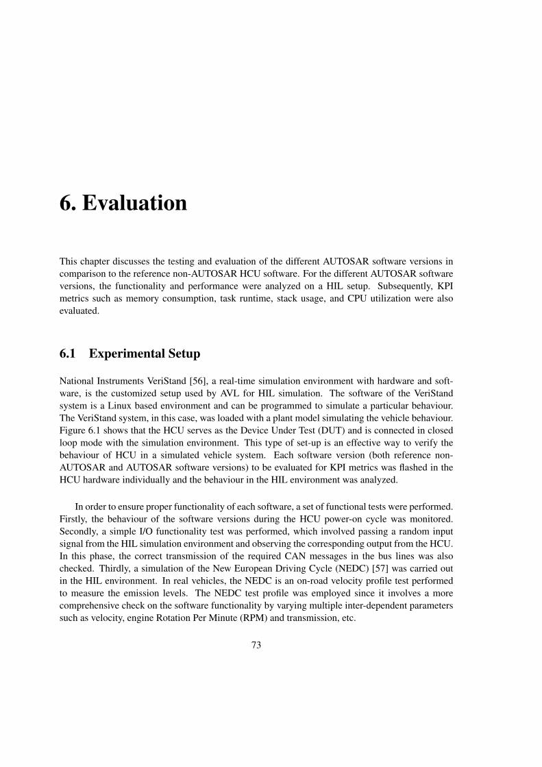
6. Evaluation
This chapter discusses the testing and evaluation of the different AUTOSAR software versions incomparison to the reference non-AUTOSAR HCU software. For the different AUTOSAR softwareversions, the functionality and performance were analyzed on a HIL setup. Subsequently, KPImetrics such as memory consumption, task runtime, stack usage, and CPU utilization were alsoevaluated.
6.1 Experimental Setup
National Instruments VeriStand [56], a real-time simulation environment with hardware and soft-ware, is the customized setup used by AVL for HIL simulation. The software of the VeriStandsystem is a Linux based environment and can be programmed to simulate a particular behaviour.The VeriStand system, in this case, was loaded with a plant model simulating the vehicle behaviour.Figure 6.1 shows that the HCU serves as the Device Under Test (DUT) and is connected in closedloop mode with the simulation environment. This type of set-up is an effective way to verify thebehaviour of HCU in a simulated vehicle system. Each software version (both reference non-AUTOSAR and AUTOSAR software versions) to be evaluated for KPI metrics was flashed in theHCU hardware individually and the behaviour in the HIL environment was analyzed.
In order to ensure proper functionality of each software, a set of functional tests were performed.Firstly, the behaviour of the software versions during the HCU power-on cycle was monitored.Secondly, a simple I/O functionality test was performed, which involved passing a random inputsignal from the HIL simulation environment and observing the corresponding output from the HCU.In this phase, the correct transmission of the required CAN messages in the bus lines was alsochecked. Thirdly, a simulation of the New European Driving Cycle (NEDC) [57] was carried outin the HIL environment. In real vehicles, the NEDC is an on-road velocity profile test performedto measure the emission levels. The NEDC test profile was employed since it involves a morecomprehensive check on the software functionality by varying multiple inter-dependent parameterssuch as velocity, engine Rotation Per Minute (RPM) and transmission, etc.
73

Evaluation
Figure 6.1: HIL test environment for evaluation.
6.1.1 Observations
All the software versions (both AUTOSAR and non-AUTOSAR versions) passed the power cycletest. The voltage and current levels of the HCU during the power-on phase were well within thepermissible levels (HCU voltage level: 12-13V; HCU current level: 0.7-0.8A). The transmission ofCAN signals in the network was also observed for all the software versions when the ignition was setto RUN state. Additionally, all the software versions passed the I/O functionality test, wherein, forsome simulated input signals, the transmission of corresponding output CAN signal was observedin the network. The above observations ensured that the software functionality in terms of OS taskexecution and runnable entity scheduling was proper in all the software versions. The AUTOSARsoftware versions, however, did not pass the simulated NEDC test, while the original AVL HCUsoftware was successful in the NEDC run. The root cause of the failure was found to be the improperfunctionality of some of the look-up table mappings in the code generated from Embedded Coder1.However, owing to time constraints, the issue with look-up table mappings could not be resolvedfor the AUTOSAR software versions and the evaluation was limited to the analysis of KPIs suchas task runtime, stack usage, and CPU utilization. The signals pertaining to the above metrics wererecorded for about 300 seconds using the Vector CANape [58] environment.
1A similar issue could not be observed in the TargetLink generated code of the original AVL HCU software.
74

Evaluation
6.2 Memory Consumption Analysis
.sdata .text .caldata .rodata .bss .data
0
0.2
0.4
0.6
0.8
1
Various Memory Sections
Mem
ory
Cos
umpt
ion
inM
B(=
106
Byt
es)
Reference SW Autosar - Normal Autosar - Inline Autosar - L1 Autosar - L2
Figure 6.2: Analysis of memory consumption.
This section compares the memory consumption of the ASW codes for the AVL HCU softwareand the different AUTOSAR software versions. The memory consumption result was generated outof the build process by a Python script, which calculates the total utilization per various memorysections by analyzing the ASW compiled object files. The description of various memory sectionsto be analyzed are as follows:
• .sdata and .data are used to store initialized static global variables. Unlike the .data section,the memory size allocated to the .sdata section is comparatively limited.
• .text section contains the code portion.
• .caldata section stores the volatile calibration and measurement variables.
• .bss section holds the uninitialized global variables.
Table 6.1 lists the memory usage in bytes associated with different memory sections for all thesoftware versions (both reference non-AUTOSAR and AUTOSAR versions). Each numeric data
75
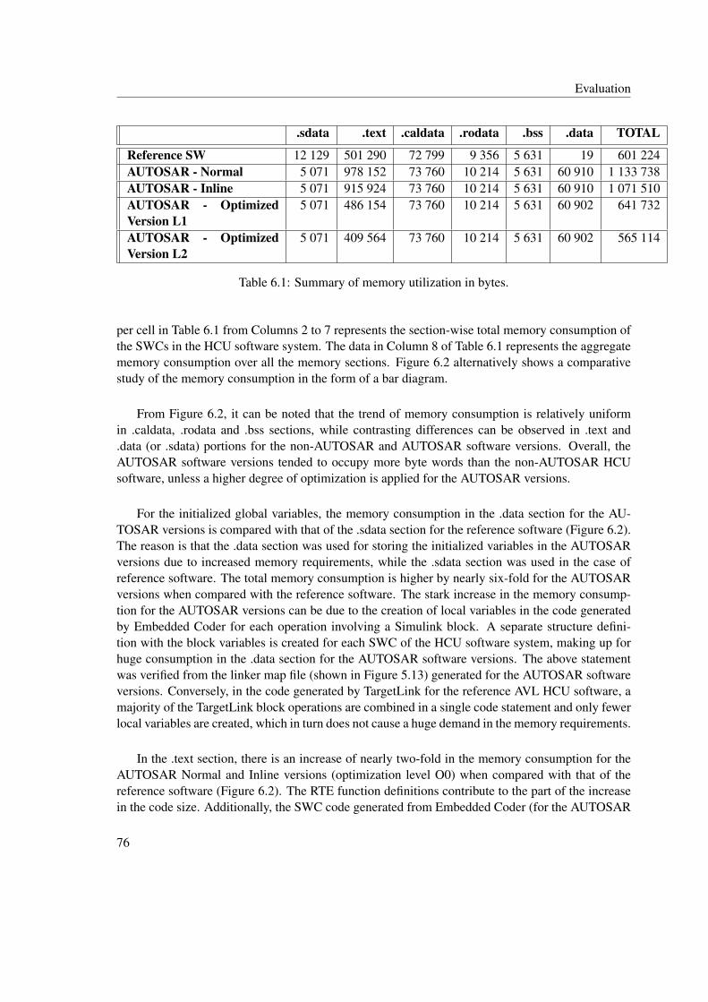
Evaluation
.sdata .text .caldata .rodata .bss .data TOTAL
Reference SW 12 129 501 290 72 799 9 356 5 631 19 601 224AUTOSAR - Normal 5 071 978 152 73 760 10 214 5 631 60 910 1 133 738AUTOSAR - Inline 5 071 915 924 73 760 10 214 5 631 60 910 1 071 510AUTOSAR - OptimizedVersion L1
5 071 486 154 73 760 10 214 5 631 60 902 641 732
AUTOSAR - OptimizedVersion L2
5 071 409 564 73 760 10 214 5 631 60 902 565 114
Table 6.1: Summary of memory utilization in bytes.
per cell in Table 6.1 from Columns 2 to 7 represents the section-wise total memory consumption ofthe SWCs in the HCU software system. The data in Column 8 of Table 6.1 represents the aggregatememory consumption over all the memory sections. Figure 6.2 alternatively shows a comparativestudy of the memory consumption in the form of a bar diagram.
From Figure 6.2, it can be noted that the trend of memory consumption is relatively uniformin .caldata, .rodata and .bss sections, while contrasting differences can be observed in .text and.data (or .sdata) portions for the non-AUTOSAR and AUTOSAR software versions. Overall, theAUTOSAR software versions tended to occupy more byte words than the non-AUTOSAR HCUsoftware, unless a higher degree of optimization is applied for the AUTOSAR versions.
For the initialized global variables, the memory consumption in the .data section for the AU-TOSAR versions is compared with that of the .sdata section for the reference software (Figure 6.2).The reason is that the .data section was used for storing the initialized variables in the AUTOSARversions due to increased memory requirements, while the .sdata section was used in the case ofreference software. The total memory consumption is higher by nearly six-fold for the AUTOSARversions when compared with the reference software. The stark increase in the memory consump-tion for the AUTOSAR versions can be due to the creation of local variables in the code generatedby Embedded Coder for each operation involving a Simulink block. A separate structure defini-tion with the block variables is created for each SWC of the HCU software system, making up forhuge consumption in the .data section for the AUTOSAR software versions. The above statementwas verified from the linker map file (shown in Figure 5.13) generated for the AUTOSAR softwareversions. Conversely, in the code generated by TargetLink for the reference AVL HCU software, amajority of the TargetLink block operations are combined in a single code statement and only fewerlocal variables are created, which in turn does not cause a huge demand in the memory requirements.
In the .text section, there is an increase of nearly two-fold in the memory consumption for theAUTOSAR Normal and Inline versions (optimization level O0) when compared with that of thereference software (Figure 6.2). The RTE function definitions contribute to the part of the increasein the code size. Additionally, the SWC code generated from Embedded Coder (for the AUTOSAR
76
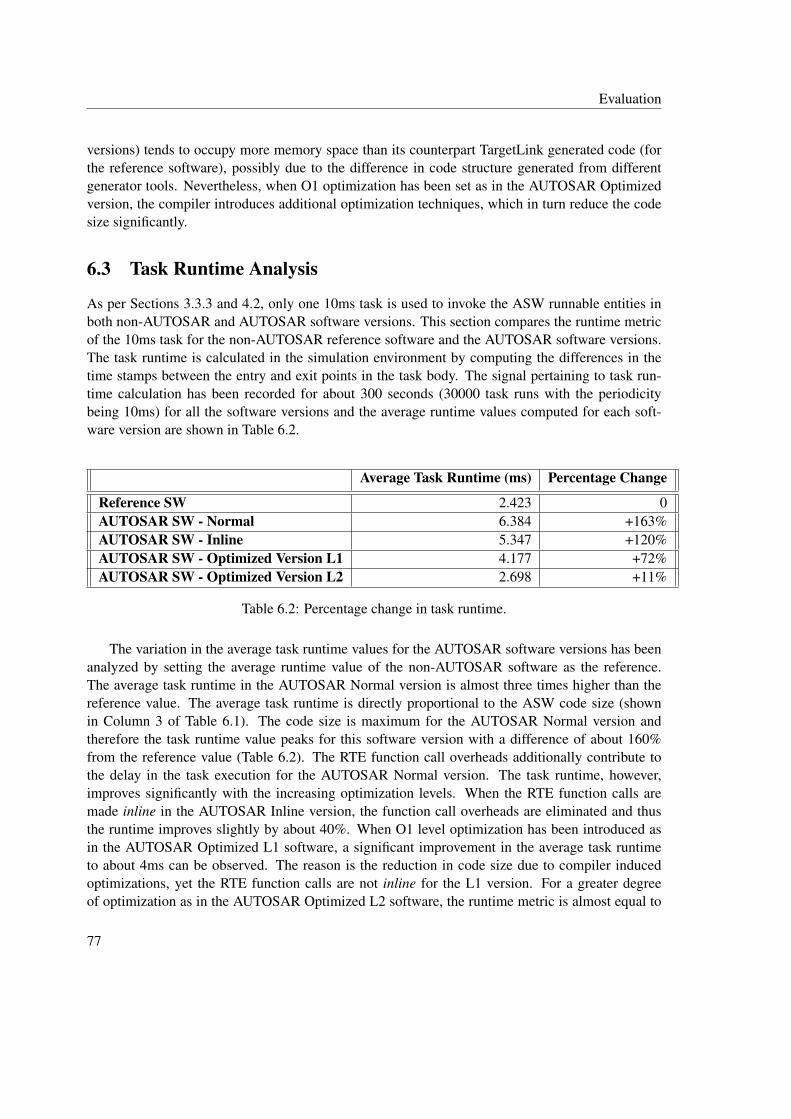
Evaluation
versions) tends to occupy more memory space than its counterpart TargetLink generated code (forthe reference software), possibly due to the difference in code structure generated from differentgenerator tools. Nevertheless, when O1 optimization has been set as in the AUTOSAR Optimizedversion, the compiler introduces additional optimization techniques, which in turn reduce the codesize significantly.
6.3 Task Runtime Analysis
As per Sections 3.3.3 and 4.2, only one 10ms task is used to invoke the ASW runnable entities inboth non-AUTOSAR and AUTOSAR software versions. This section compares the runtime metricof the 10ms task for the non-AUTOSAR reference software and the AUTOSAR software versions.The task runtime is calculated in the simulation environment by computing the differences in thetime stamps between the entry and exit points in the task body. The signal pertaining to task run-time calculation has been recorded for about 300 seconds (30000 task runs with the periodicitybeing 10ms) for all the software versions and the average runtime values computed for each soft-ware version are shown in Table 6.2.
Average Task Runtime (ms) Percentage Change
Reference SW 2.423 0AUTOSAR SW - Normal 6.384 +163%AUTOSAR SW - Inline 5.347 +120%AUTOSAR SW - Optimized Version L1 4.177 +72%AUTOSAR SW - Optimized Version L2 2.698 +11%
Table 6.2: Percentage change in task runtime.
The variation in the average task runtime values for the AUTOSAR software versions has beenanalyzed by setting the average runtime value of the non-AUTOSAR software as the reference.The average task runtime in the AUTOSAR Normal version is almost three times higher than thereference value. The average task runtime is directly proportional to the ASW code size (shownin Column 3 of Table 6.1). The code size is maximum for the AUTOSAR Normal version andtherefore the task runtime value peaks for this software version with a difference of about 160%from the reference value (Table 6.2). The RTE function call overheads additionally contribute tothe delay in the task execution for the AUTOSAR Normal version. The task runtime, however,improves significantly with the increasing optimization levels. When the RTE function calls aremade inline in the AUTOSAR Inline version, the function call overheads are eliminated and thusthe runtime improves slightly by about 40%. When O1 level optimization has been introduced asin the AUTOSAR Optimized L1 software, a significant improvement in the average task runtimeto about 4ms can be observed. The reason is the reduction in code size due to compiler inducedoptimizations, yet the RTE function calls are not inline for the L1 version. For a greater degreeof optimization as in the AUTOSAR Optimized L2 software, the runtime metric is almost equal to
77

Evaluation
the reference value. In addition to the O1 optimization flag, the L2 version also includes inlinedRTE functions, which improves the average task runtime potentially. Overall, the non-AUTOSARsoftware fared better than the AUTOSAR versions in the runtime analysis. However, a significantimprovement in the performance of AUTOSAR versions could be observed with different optimiza-tion settings. In addition, a detailed analysis in the OS level, such as the variations in the kerneltime and communication overheads, was not performed since the BSW supplier does not providethe required interfaces to measure these parameters.
6.4 CPU Utilization Analysis
Average CPU Utilization (%) Percentage Change
Reference SW 64.29 0AUTOSAR SW - Normal 53.84 -16%AUTOSAR SW - Inline 91.14 +41%AUTOSAR SW - Optimized Version L1 80.94 +25%AUTOSAR SW - Optimized Version L2 66.70 +3%
Table 6.3: Percentage change in CPU utilization.
CPU utilization factor is the measure of the percentage of CPU time being used for programexecution in comparison with the CPU idle time. As indicated in Section 5.3, the CPU in this contextrefers to the Infineon Aurix 32-bit TC275. The algorithm of CPU usage calculation is implementedin the BSW by the supplier. The implementation of CPU usage calculation is however abstracted inthe BSW object files delivered to AVL and the supplier provides only the signal interpreting the CPUutilization, which can be read in the Vector CANape environment. This signal measures the overallCPU usage (in percentage) by the BSW OS and not just the CPU usage factor of the 10ms task. Thesignal measuring the CPU usage was recorded for about 300 seconds and the average CPU usagefactor observed for each software versions is tabulated in Table 6.3. Column 2 of Table 6.3 showsthat average CPU usage factor observed in AUTOSAR Normal version does not correlate with theother AUTOSAR versions. The exact reason for this variation is not clearly known. However,looking at the trend of observations in the other AUTOSAR versions (Inline and Optimized) and thereference software, it has been assumed that the CPU usage factor coincides with the task runtime.More the task runtime, higher is the CPU usage factor, although the execution of CAN interruptscan also contribute to the latter. Even though the CPU usage factor of the AUTOSAR Inline versionwas critically just over 90%, the program execution was stable in all the cases and no situation ofsystem overloading (CPU usage factor of 100%) had occurred, in which case, an ECU reset mighthave been triggered.
78
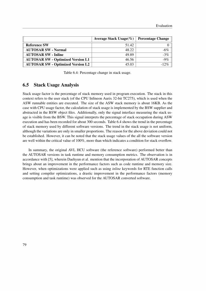
Evaluation
Average Stack Usage(%) Percentage Change
Reference SW 51.42 0AUTOSAR SW - Normal 48.22 -6%AUTOSAR SW - Inline 49.89 -3%AUTOSAR SW - Optimized Version L1 46.56 -9%AUTOSAR SW - Optimized Version L2 45.03 -12%
Table 6.4: Percentage change in stack usage.
6.5 Stack Usage Analysis
Stack usage factor is the percentage of stack memory used in program execution. The stack in thiscontext refers to the user stack (of the CPU Infineon Aurix 32-bit TC275), which is used when theASW runnable entities are executed. The size of the ASW stack memory is about 16KB. As thecase with CPU usage factor, the calculation of stack usage is implemented by the BSW supplier andabstracted in the BSW object files. Additionally, only the signal interface measuring the stack us-age is visible from the BSW. This signal interprets the percentage of stack occupation during ASWexecution and has been recorded for about 300 seconds. Table 6.4 shows the trend in the percentageof stack memory used by different software versions. The trend in the stack usage is not uniform,although the variations are only in smaller proportions. The reason for the above deviation could notbe established. However, it can be noted that the stack usage values of the all the software versionare well within the critical value of 100%, more than which indicates a condition for stack overflow.
In summary, the original AVL HCU software (the reference software) performed better thanthe AUTOSAR versions in task runtime and memory consumption metrics. The observation is inaccordance with [5], wherein Daehyun et al. mention that the incorporation of AUTOSAR conceptsbrings about an improvement in the performance factors such as code runtime and memory size.However, when optimizations were applied such as using inline keywords for RTE function callsand setting compiler optimizations, a drastic improvement in the performance factors (memoryconsumption and task runtime) was observed for the AUTOSAR converted software.
79

Evaluation
80
7. Conclusion
This chapter presents a brief outlook on the research carried out in this thesis, discusses someinferences, and provides some recommendations for further research.
7.1 Summary
The aim of this thesis was to convert the AVL HCU software towards AUTOSAR compliance and todistinctly establish an AUTOSAR software development methodology for AVL Powertrain ControlsDept. The software deviations from the AUTOSAR concepts had to be observed not only at the soft-ware architecture level but also along each and every phase of software development. Therefore, theanalysis of software deviation was performed along the SDLC, namely the V-Model. A comparisonwas made between the AUTOSAR methodology and the AVL’s methodology, and it had been thor-oughly analyzed on the expectations when AVL chooses to follow AUTOSAR methodology in thefuture. In terms of software conversion to AUTOSAR, a concept was proposed, in which, the ASWwas converted to AUTOSAR format and integrated with the BSW via the RTE layer generation. TheBSW, which is not AUTOSAR compliant, had been reused, and the CIL layer had been retained.The RTE portion was generated tailoring the need for integration. The resulting software did notmeet the ICC3 conformance level however, it could satisfy AUTOSAR ICC1 requirements. MAT-LAB scripts were additionally developed to automate the ASW conversion and the RTE generation.Out of all the MATLAB scripts used in this thesis, the delivery scripts (Section 5.1.3) were providedby AVL. Additionally, in PrepareAUTOSARDelivery.m (Section 5.1.4), the algorithms involving thepreparation of models for AUTOSAR conversion and the conversion of model parameters and sig-nals to the AUTOSAR package were developed by AVL for a customer project and were adoptedin this thesis. In the system build, a total of four versions of AUTOSAR HCU software with dif-ferent optimization techniques were prepared. These AUTOSAR software versions were validatedon a HIL set up and the performance metrics such as the memory consumption, task runtime, CPUusage, and stack usage were compared with a reference non-AUTOSAR AVL HCU software.
81
Evaluation
7.2 Discussion
Although it has been said that the software is compliant with AUTOSAR, an ICC3 level AUTOSARcompliance was still not achievable due to the following factors:
• The usage of non-AUTOSAR BSW in the conversion concept to AUTOSAR.
• The presence of the CIL layer and its supplier-specific interfaces to the BSW.
• The I/O Hardware Abstraction handling (Section 3.3.2) has not been implemented as perAUTOSAR standards. This is partly due to the non-AUTOSAR BSW.
• The absence of RTE events for actuating the dynamic behaviour of ASW.
The reason here is quite obvious: The AUTOSAR methodology has not been followed from scratchof the development process. It can be inferred that it is highly unlikely to incorporate the AUTOSARspecific concepts at the granular level without following the AUTOSAR methodology completely.When an ICC3 level AUTOSAR compliance is aimed, it is imperative to use the AUTOSAR spe-cific BSW stacks for integration with the ASW, along with the standard AUTOSAR toolchains forconfiguration and RTE generation. The above observation is also supported in the work by Daehyunet al. [5]. In the proposed conversion concept, the BSW has been reused since AUTOSAR specificBSW stacks were not procured for this project. The CIL has been retained since more manual mod-ification in the code level may be required if the layer has to be removed. The AUTOSAR based I/Oaccess mechanism using ECU Abstraction type SWC can be implemented only with AUTOSARspecific BSW stacks and has to be configured during the BSW configuration phase. In addition, theRTE events are also included in the AUTOSAR ICC3 implementation, and they have to be config-ured in the BSW configuration phase. These RTE events are however not part of the BSW (used inthis thesis) implementation by the supplier and therefore are not used in the AUTOSAR convertedsoftware. The AUTOSAR conversion concept proposed in this thesis can meet ICC1 conformancerequirements since the interfaces between the ASW and the cluster consisting of RTE, BSW, andthe CIL are standardized via RTE function calls (Section 4.2). Moreover, this conversion approachcannot be adopted for all the non-AUTOSAR legacy software models. It is rather dependent onthe architecture of the legacy software. In some cases, the complete ASW functionality has to bedecomposed into specific AUTOSAR SWC types, as indicated by Daehyun et al. [5]. As there wereabout 40 non-AUTOSAR AVL HCU software models to be converted to AUTOSAR format in thiswork, MATLAB scripts were developed to automate the model conversion to AUTOSAR and codegeneration. The application SWCs thus converted to AUTOSAR format can also be deployed in anAUTOSAR system (with AUTOSAR BSW stacks). However, in this case, the RTE portion has togenerated only using standard RTE generator tools. The RTE generator script used in this thesiswas developed keeping in mind the conversion concept shown in Figure 4.1 and cannot substitute astandard RTE generator tool since the script generates only the RTE function definitions involvingSWC communication and parameter access. The RTE generator script, however, is further modifi-able and can be adapted in the future based on the structure of the RTE code needed. Furthermore,in terms of performance, the non-AUTOSAR software version fared better than the AUTOSAR
82

Evaluation
versions in execution time and memory consumption analysis. The reasons are the increase in thecode size for the AUTOSAR versions and the function call overheads introduced by the RTE func-tion calls. Daehyun et al. [5] additionally indicate that the incorporation of AUTOSAR conceptscan lead to an increase in code size and execution time. Nevertheless, with several optimizationtechniques such as compiler induced optimizations and inlined function calls, it is shown that theperformance of AUTOSAR versions can be significantly improved. Finally, in comparison with thecurrent AVL software development methodology, which also involves manual implementation ofthe CIL, the migration to AUTOSAR methodology provides some benefits such as the eliminationof manual effort necessary in coding the CIL layer. However, if AVL chooses to follow AUTOSARmethodology, additional configuration steps of the BSW modules and the RTE are also involved.
7.3 Recommendation
Based on the above discussions, further works can be carried out in one of the following areas:
• The ICC1 compliant HCU software in the next stage can be converted to a fully AUTOSARcompliant ICC3 software. The AUTOSAR converted ASW models can be integrated withAUTOSAR specific BSW stacks with the necessary configuration and RTE generation. Theperformance metrics of the ICC3 software can also be analyzed in comparison with the ICC1software.
• It has been said based on theoretical concepts that an ICC1 level of AUTOSAR compliancehas been achieved. Yet this compliance level is still not certified. Gilberg et al. [59] mentionthe AUTOSAR conformance test scenarios and the conformance certification by a third partyagency. The software, in the next stage, can be subjected to conformance certification andin case any deviations detected from the standard, the conversion concept can be furtherimproved.
• Thomas [60] mentions various optimization techniques at the BSW level to improve memoryusage and runtime performances. However, these optimization techniques cannot be appliedto the BSW used in the thesis since the BSW implementation is abstracted in the object filesdelivered to AVL. In case customizable AUTOSAR specific BSW stacks are used for integra-tion with ASW, the effects of these optimization techniques on the software performance canbe further studied. [61] and [62] further discuss other categories of optimizations that can beapplied such as in the scheduling mechanism of OS tasks or in the processing of the signalstransmitted via the COM module.
• Although the CPU used in this thesis (Infineon Aurix Tricore) is multi-core, only a single coreis used for software execution. The multi-core support has been included from AUTOSAR4.0, and so, the possible extension of the software towards a multi-core platform can alsobe investigated once the ICC3 compliance is achieved. [63] and [64] serve as good startingpoints, which analyze various strategies and challenges towards multi-core migration.
83

Evaluation
84

A. Format of Memory Mapping Keyword(AUTOSAR)
The AUTOSAR specification [31] defines a general format for the memory mapping keyword:
<COMPONENT_PREFIX>_START/STOP_SEC_<NAME>
where
• <COMPONENT_PREFIX> indicates the module abbreviation of the SWC.
• <NAME> denotes the memory section types: VAR for variables, CODE for code portion,CONST for constants and CALIB for calibration variables.
The VAR section can additionally include:
• Initialization policy <INIT_POLICY> postfix, which indicates the initialization (or cleared)status of the variables after reset or power cycle. Some of the postfixes are: INIT, NO_INITand CLEARED.
• Variable alignment <VAR_ALIGNMENT> postfix, which indicates the size of the variablesand can be denoted by one of the following postfixes: BOOLEAN, 8 bit, 16 bit, 32 bit, PTRand UNSPECIFIED.
85
B. Format of Memory Mapping Keyword(AVL HCU Software)
The BSW supplier of AVL HCU software defines the memory mapping keyword in the followingformat [12]:
ASW_OEM_START_SEC_<DEFAULT/SMALL>_<NAME>
where
• The declaration of all fast accessible variables (variables to be placed in .sdata and .sbsssections in the memory) is placed under the keyword with SMALL. The DEFAULT postfix isused for all the other types of variables and the runnable entity definitions.
• <NAME> denotes the different memory section types. The code portion is placed under thepostfix CODE. The variable declarations are additionally placed with the following details:
– Initialization policy: INIT for variables initialized to previous values after reset (orpower cycle); CLEARED for variables cleared to zero.
– Allocated size of the variables: 8, 16, 32, UNSPECIFIED.
86
C. tl_clear_system
Used to clear TargetLink blocks.
Syntax
[options, msg] = tl_clear_system(’system’, Model)
Description
Clears the TargetLink properties of the Model. The output variable msg is a structure that containslogs from deenhancement. The variable options is a structure that contains the options used.
87

D. autosar.api.create
Creates an AUTOSAR component for models developed in Simulink [45].
Syntax
autosar.api.create(Model, ’default’)
Description
Creates default AUTOSAR component for Model with all ports configured as Implicit Send/Receiveand returns AUTOSAR properties as Simulink object.
88

E. arxml.importer
Imports ARXML file as MATLAB objects [45].
Syntax
arProps = arxml.importer(componentname)
Description
Imports the ARXML with the componentname and returns AUTOSAR properties as Simulink objectto arProps.
89

F. find
Used to find the paths of AUTOSAR entities [45].
Syntax
1. find(arProps, [], SWCEntity, ’PathType’, ’FullyQualified’)
2. find(arProps, aswcPath{1}, PortEntity, ’PathType’, ’FullyQualified’)
3. find(arProps, paramcomp{1}, PortEntity, ’PathType’, ’FullyQualified’)
Description
1. For the given AUTOSAR properties arProps, the function finds the paths of one of the fol-lowing AUTOEntities and returns as MATLAB cell array:
• AUTOEntitiy = ’AtomicComponent’ for Application SWC
• AUTOEntitity = ’ParameterComponent’ for Parameter SWC
• AUTOEntitity = ’SystemConst’ for system constants
• AUTOEntitity = ’ExclusiveArea’ for local signals
2. For the given AUTOSAR properties arProps and aswcPath, the function finds the paths ofone of the following PortEntities and returns as MATLAB cell array:
• PortEntity = ’DataRecieverPort’ for Receiver ports
• PortEntity = ’DataSenderPort’ for Sender ports
• PortEntity = ’ParameterData’ for parameters
• PortEntity = ’Runnable’ for runnable entities
3. For the given AUTOSAR properties arProps and paramComp, the function finds the paths ofone of the following PortEntities and returns as MATLAB cell array:
90
Evaluation
• PortEntity = ’ParameterSenderPort’ for Parameter Sender ports
• PortEntity = ’ParameterReceiverPort’ for Parameter Receiver ports
91

Evaluation
92

Bibliography
[1] ISO/ISE, "Guide 2: Standardization and related activities — General vocabulary," ISO Guides,Eighth Edition, 2004. [Online]. Available: https://www.iso.org/iso-guides.html [AccessedNovember 2, 2018].
[2] Nicolas Navet and Françoise Simonot-Lion, Automotive Embedded Systems Handbook, CRCPress, Taylor & Francis, no. of pages 488, 2008.
[3] AUTOSAR Website. [Online]. Available: www.autosar.org [Accessed December 12, 2018].
[4] Atul Dixit, "AUTOSAR and Embedded Info," Wordpress.com, 2016. [Online]. Available:https://automotiveembeddedsite.wordpress.com/why-autosar-what-it-is/ [Accessed November3, 2018].
[5] Daehyun Kum, Gwang-Min Park, Seonghun Lee and Wooyoung Jung, "AUTOSAR Migrationfrom Existing Automotive Software,” in International Conference on Control, Automation andSystems 2008, Seoul, Korea, pp. 558-562, 2008.
[6] James Joy, Anush G Nair, "Automation framework for converting legacy application to AU-TOSAR System using dSPACE SystemDesk," in dSPACE User Conference 2012 - India,September 14, 2012.
[7] Shiquan Piao, Hyunchul Jo, Sungho Jin, and Wooyoung Jung, "Design and Implementationof RTE Generator for Automotive Embedded Software," in 2009 Seventh ACIS InternationalConference on Software Engineering Research, Management and Applications, pp. 159-165,2009.
[8] AUTOSAR CP Release 4.3.1, "Specification of VFB," Document ID: 056, Classic Platform,2017.
[9] Denil J., Demeyer S., De Meulenaere P., Maudens K., Van Stechelman K., "Migrating from aProprietary RTOS to the OSEK Standard Using a Wrapper," In: Conti M., Orcioni S., MartínezMadrid N., Seepold R. (eds) Solutions on Embedded Systems. Lecture Notes in ElectricalEngineering, Springer, Dordrecht, vol 81, pp 241-254, 2011.
93

Bibliography
[10] Schoof, J. and Wybo, D., "No Detour Needed: Getting to AUTOSAR via OSEK," SAE Tech-nical Paper 2006-01-0168, 2006.[DOI: https://doi.org/10.4271/2006-01-0168]
[11] OSEK/VDX, "Operating System Specification 2.2.3," Version 2.2.3, February 17, 2005.
[12] Lufeng Zhao, "VCU 8: BSW User Manual," UAES, AVL Internal Documents, 2018.
[13] William Weinberg, "Moving Legacy Applications to Linux: RTOS Migration Revisited,"white paper, MontaVista Software Inc., Version 2.1, July 29, 2007.
[14] Franck Fleurey, Erwan Breton, Benoit Baudry, Alain Nicolas, Jean-Marc Jézéquel, "Model-Driven Engineering for Software Migration in a Large Industrial Context," MODELS 2007:Model Driven Engineering Languages and Systems, Springer Berlin, Heidelberg, LectureNotes in Computer Science, Vol 4735, pp 482-497, 2007.
[15] AUTOSAR CP Release 4.3.1, "Specification of RTE Software," Document ID: 084, ClassicPlatform, 2017.
[16] AUTOSAR CP Release 4.3.1, "Layered Software Architecture," Document ID: 053, ClassicPlatform, 2017.
[17] AUTOSAR, "Specification of BSW Module Description Template," Document ID: 089, 2014.
[18] "Hybrid Control Unit - SW Architecture Document," Version 1.0, AVL Internal Documents,2018.
[19] "S5 PHEV HCU HW & BSW Requirements," Document ID: 1117918, AVL Internal Docu-ments, 2018.
[20] Rajkumar, "Software Development Life Cycle – SDLC | Software Testing Material". [On-line]. Available: https://www.softwaretestingmaterial.com/sdlc-software-development-life-cycle/ [Accessed November 14, 2018].
[21] Andreq Powell-Morse, "V-Model: What Is It And How Do You Use It?," Airbrake, 2016.[Online]. Available: https://airbrake.io/blog/sdlc/v-model [Accessed November 14, 2018].
[22] Rajkumar, "V-Model in SW Development Lifecycle," www.softwaretestingmaterial.com,2018. [Online]. Available: https://www.softwaretestingmaterial.com/v-model-in-sdlc/ [Ac-cessed November 14, 2018].
[23] AUTOSAR CP Release 4.3.1, "Specification of Diagnostic Event Manager," Document ID:019, Classic Platform, 2017.
[24] AUTOSAR CP Release 4.3.1, "Specification of I/O Hardware Abstraction," Document ID:047, Classic Platform, 2017.
[25] AUTOSAR CP Release 4.3.1, "Guide to Mode Management," Document ID: 440, ClassicPlatform, 2017.
94

Bibliography
[26] AUTOSAR CP Release 4.3.1, "NV Data Handling Guideline," Document ID: 810, ClassicPlatform, 2017.
[27] AUTOSAR CP Release 4.3.1, "Specification of Operating System," Document ID: 034, Clas-sic Platform, 2017.
[28] "ADD V19.1 Product Datasheet," VisuIT, 2019. [Online]. Available: https://www.visu-it.de/vitdata/Download/pub/10_ADD/ADD_Info/DataSheet.pdf [Accessed May 24, 2019].
[29] Sandmann, G. and Thompson, R., "Development of AUTOSAR Software Compo-nents within Model-Based Design," SAE Technical Paper 2008-01-0383, 2008.[DOI:https://doi.org/10.4271/2008-01-0383]
[30] Shwetha B.M, "Simulink Advance Support for AUTOSAR: Compositions, BSW Ser-vices Simulation and Code Generation," Mathworks Videos and Webminar, The Math-Works, Inc., 2018. [Online]. Available: https://www.mathworks.com/videos/simulink-advance-support-for-autosar-compositions-bsw-services-simulation-and-code-generation-1522678366273.html [Accessed February 2, 2019].
[31] AUTOSAR CP Release 4.3.1, "Specification of Memory Mapping," Document ID: 128, Clas-sic Platform, 2017.
[32] Intel, "Hexadecimal Object File Format Specification," Revision A, 1988. [Online]. Available:https://archive.org/details/IntelHEXStandard [Accessed June 12, 2019].
[33] Hightec Compiler Suite Product Information, HighTec EDV-Systeme GmbH, 2019. [Online].Available: https://hightec-rt.com/en/products/development-platform.html [Accessed May 24,2019].
[34] Matthias Wernicke, Webminar on "AUTOSAR Configuration Process - How to handle 1000sof Parameter," Vector Informatik GmbH, 19 Apr., 2013. [Online]. Available: https://vector-academy.com/vi_training_elearning_en.html [Accessed January 12, 2019].
[35] Matthias Wernicke, Webinar on "Introduction to the AUTOSAR Method of ECU De-velopment," Vector Informatik GmbH, Apr. 17, 2013. [Online]. Available: https://vector-academy.com/vi_training_elearning_en.html [Accessed February 24, 2019].
[36] PrEEvision Product Information, Vector Informatik GmbH, 2019. [Online]. Available:https://www.vector.com/int/en/products/products-a-z/software/preevision/ [Accessed Febru-ary 24, 2019].
[37] DaVinci Configurator Pro Product Information, Vector Informatik GmbH, 2019.[Online]. Available: https://www.vector.com/at/en/products/products-a-z/software/davinci-configurator-pro/ [Accessed February 28, 2019].
[38] AUTOSAR GbR, "Specification of ECU Configuration," Version 1.0.1, 2006. [On-line]. Available: https://www.autosar.org/fileadmin/user_upload/standards/classic/2-0/AUTOSAR_ECU_Configuration.pdf [Accessed February 28, 2019].
95

Bibliography
[39] Regina Hebig, "Methodology and Templates in AUTOSAR," Citeseer, 2009. [Online]. Avail-able: http://citeseerx.ist.psu.edu/viewdoc/download?doi=10.1.1.596.2903&rep=rep1&type=pdf[Accessed August 8, 2019].
[40] AUTOSAR CP Release 4.3.1, "General Specification of Basic Software Modules," DocumentID: 578, Classic Platform, 2017.
[41] Microsar Product Information, Vector Informatik GmbH., 2019. [Online]. Available:https://vector.com/pi_microsar_en/ [Accessed January 12, 2019].
[42] DaVinci Developer Product Information, Vector Informatik GmbH, 2019. [Online]. Avail-able: https://www.vector.com/at/en/products/products-a-z/software/davinci-developer/ [Ac-cessed April 24, 2019].
[43] Mathworks Documentation on "Code Generation Options," The MathWorks, Inc. [On-line]. Available: https://de.mathworks.com/help/simulink/gui/simulink-coder-options.html[Accessed August 8, 2019].
[44] Mathworks Documentation on "Packages Create Namespaces," The MathWorks, Inc. [On-line]. Available: https://de.mathworks.com/help/matlab/matlab_oop/scoping-classes-with-packages.html [Accessed August 8, 2019].
[45] Matlab User Manual on "Embedded Coder AUTOSAR" for Matlab 2016b, The MathWorks,Inc., 2016.
[46] Matlab Documentation on "Target Language Compiler," The MathWorks, Inc. [Online]. Avail-able: https://de.mathworks.com/help/rtw/block-authoring-with-tlc.html [Accessed April 19,2019].
[47] AUTOSAR CP Release 4.3.1, "Specification of Platform Types," Document ID: 048, ClassicPlatform, 2017.
[48] 32-bit Aurix Tricore TC275 Product Information, Infineon AG, 2019. [Online]. Available:https://www.infineon.com/cms/de/product/microcontroller/32-bit-tricore-microcontroller/32-bit-tricore-aurix-tc2xx/ [Accessed May 24, 2019].
[49] ASAM Standards, ASAM e.V, 2019. [Online]. Available:https://www.asam.net/standards/detail/mcd-2-mc/wiki/ [Accessed May 24, 2019].
[50] DDS Product Information, VisuIT, 2019. [Online]. Available: https://www.visu-it.de/products/dds/ [Accessed May 24, 2019].
[51] Tool Interface Standards, "Executable and Linkable Format (ELF)," Version 1.1. [Online].Available: http://flint.cs.yale.edu/cs422/doc/ELF_Format.pdf [Accessed July 24, 2019].
[52] UDE Microcontroller Debugger, PLS Development Tools, 2019. [Online]. Available:https://www.pls-mc.com [Accessed August 14, 2019].
96

Bibliography
[53] Herbert Schildt, C - The Complete Reference, Fourth Edition, McGraw - Hill, no. of pages876, 2000.
[54] "TriCore Development Platform - User’s Guide v4.6.6.1," HighTec EDV-Systeme GmbH.,2016.
[55] Sharang Kulkarni, Prof. Shafali Gupta, Rameez Tamboli, Anil Dake, "Review of Techniquesfor Making Efficient Executable in GCC Compiler," in Imperial Journal of InterdisciplinaryResearch (IJIR), Vol-3, Issue-3, 2017. [Online]. Available: https://www.semanticscholar.org[Accessed August 12, 2019].
[56] VeriStand Product Information, National Instruments, 2019. [Online]. Available:http://www.ni.com/veristand/ [Accessed June 06, 2019].
[57] New European Driving Cycle, Wikipedia, 2019. [Online]. Available:https://en.wikipedia.org/wiki/New_European_Driving_Cycle [Accessed August 14, 2019].
[58] Vector CANape Product Information, Vector Informatik GmbH, 2019. [Online]. Available:https://www.vector.com/int/en/products/products-a-z/software/canape/ [Accessed August 17,2019].
[59] Alain Gilberg, Bernd Kunkel, Alain Ribault, Philippe Robin, Noë Spinner. "ConformanceTesting for the AUTOSAR Standard," ERTS2 2010, Embedded Real Time Software Sys-tems, Toulouse, France, May 2010. [Online]. Available: https://hal.archives-ouvertes.fr/hal-02264390/document [Accessed August 17, 2019].
[60] Thomas M Galla, "Beyond AUTOSAR – Optimized AUTOSAR Compliant Basic SoftwareModules," ResearchGate, 2008. [Online]. Available: https://www.researchgate.net/ [AccessedAugust 18, 2019].
[61] Zhao, Qingling, Gu, Zonghua, Zeng, Haibo, “Design optimization for AUTOSAR models withpreemption thresholds and mixed-criticality scheduling,” in Journal of Systems Architecture,Vol 72, pp 61-68, 2017.
[62] Jeong-Hwan Lee, Hyun Yong Hwang, Tae Man Han and Yong Hak Ahn, “A Study on signalgroup processing of AUTOSAR COM Module,” in Journal of Physics: Conference Series, Vol450, No.1,012034, 2013.[ DOI:10.1088/1742-6596/450/1/012034].
[63] Georg Macher, Andrea Hoeller, Eric Armengaud and Christian Kreiner, "Automotive Em-bedded Software: Migration Challenges to Multi-Core Computing Platforms," in 2015 IEEE13th International Conference on Industrial Informatics (INDIN), pp. 1389-1393, 2015.[DOI:10.1109/INDIN.2015.7281937]
[64] Simon Widlund and Anton Annenkov, "Migrating a Single-core AUTOSAR Application to aMulti-core Platform: Challenges, Strategies and Recommendations," Master’s thesis in Com-puter Science and Engineering, Chalmers University of Technology, 2017.
97


![Leistungsmodell Generalplanung [LM.GP] … 7hloh *(6$07%($5%(,781* 3urmhnwpdqdjhphqw 7rrov 6hplqduh 6riwzduh 9huodj $ :lhq 6fkrwwhqihogjdvvh zzz spwrrov hx 'lh $uehlw lq %dxsurmhnwhq](https://img.dokumen.tips/doc/110x75/5ae9fd077f8b9ac3618d21b4/leistungsmodell-generalplanung-lmgp-7hloh-6075781-3urmhnwpdqdjhphqw.jpg)

![University of Groningen Real-world influenza vaccine ... · &kdswhu srlqwhg wrzdugv vrph hiihfwlyhqhvv wkh uhgxfwlrq lq oderudwru\ frq¿uphg lqÀxhq]drxwfrphzdvqrwvwdwlvwlfdoo\vljql¿fdqw](https://img.dokumen.tips/doc/110x75/5e5fc77a89d54b408170d3bc/university-of-groningen-real-world-influenza-vaccine-kdswhu-srlqwhg-wrzdugv.jpg)


![DQG 3UHIHUHQFH WRZDUGV 3DWDQMDOL 5HWDLO 3URGXFWV · # ,-765' _ $ydlodeoh 2qolqh # zzz lmwvug frp /^^e e } w î ð ñ ò / v v ] } v o z z](https://img.dokumen.tips/doc/110x75/5ed6c67bd1c832032836c896/dqg-3uhihuhqfh-wrzdugv-3dwdqmdol-5hwdlo-3urgxfwv-765-ydlodeoh-2qolqh-zzz.jpg)