Embed Size (px)
Citation preview

Amn~ ~~pia if~I~tf to
0. -
7,; IT~;
tr 4~but Io n 6-f thia doauned -

DISCLAIMER NOTICEI-
THIS DOCUMENT IS BESTQUALITY AVAILABLE. THE COPY
FURNISHED TO DTIC CONTAINED
A SIGNIFICANT NUMBER OF
PAGES WHICH DO NOT
REPRODUCE LEGIBLY.

03
CONTINENTAL AVIATION AND ENGINEERING (CORPORATIONDETROIT, MICHIGAN
AMMONIA APPLICATIONTO RECIPROCATING ENGINES
FINAL TECHNICAL REPORTCONTRACT DA-20-113-AMC-05553(T)
This work was performed under the technical,supervision of the Detroit Arsenal, Warren,Michigan, under Contract DA-20-113-AMC-05553(T),administered by the Detroit Procurement District,1580 :East Grand Boulevard, Detroit, Michigan, 48211..
Distribu.tion of this doeuientis ±8unlimited. tmn
Reported By Approved Bey
Tho as J. Pearsall VOIMS -
.CAF R enort No. 1054 May 1961
14T,
I. -

CAE ReportNo. 1054Volume I - May 1967
SUMMARY
Two engines, one naturally aspirated spark-4gn, on and one supercharg-ed compression-ignition, were successfully converted to 6perate with anhydrotammonia as fuel in lieu of the hydrocarbon fuel normally used.
Conversion of the spark-ignition engine r.equired the following changes:
1. Increase of compression ratio.
2. Provide an ammonia carburetor.
3. Provide a high energy ignition source (magneto).
4. Provide long reach spark plugs.
The final configuration of the spark-ignition engine was able to deliver a- maximum of 41 horse-power' on ammonia alone and 53 horsepower on ammonia
plus 1.5 percent hydrogen. The maximum output with gasoline was 65 hor-se-power. Higher outputs on ammonia were available but performance had to bcurtailed because of high firing pressures and the danger of fa. iing the cast ironcrankshaft in, the partic, lar engine tested.
The compression-ignition -engine was converted to opei:at, 'with ammoniafuel in two different configurations. The first version was achie&--d by simply
:pp!ying ammonia vapor in the induction air system and using the fuel injec-tion system to furnish a pilot charge for ignition purposes. With this arrange--1 ment the engine was able to produce as much- as 132 percent of diesel fuel ouat-put while operating within the same limits of exhaust gas temperature and peakcylinder pressures. The quantities of diesel-pilot fuel were as low as two cubicmillimeters per stroke.
A second version of the compression-ignition engine to run -on ammoniafuel was a conversion to spark-ignition by doing the following:
I. Remove the fuel injection pump and install a magneto.
2. Remove the fue.1 infyeLon nozzles arid install long reach sparkplugs.
o 3. Provide for aspiration of aimonia vapor into the induction airsystem.
I-oI

CAE Report No. 1054Volume I - May 1967
SUMMARY
Performance with the spark-ignition conversion, exceeded that withdiesel pilot fuel. Effect of varying the compression ratio was also investi-gated.
Direct injection. of liquid ammonia into a high compression ratio (30:1) engine was attempted and was unsuccessful.
Various other auxiliary aids such as fuel at ditives, ionization andradio frequency dissociation were also investigated.
A total of 1128 engine test hours were accumulated on the spark-ignition engine of which 1045 were with ammonia fuei; 954 hours (911 withammonia) were accumul'ated onthe compressi t -ignition engine.
FOREWORD
Logistics studies of Army operations, in World War II and Korea es-tablished, that apprcximately 65 percerft of the tbtal tonnage required for sup-port of combat-operations iconsisted of fuels and lubricants. To compoundthis already heavy logistical, burden, future Army concepts envision increas-ed mechanication and greater emphasis on mobility and dispersicn. Facedwith these problems, the Army searched for other materials arid devices forvehicle propulsion. Nuclear energy seemed to be the apparent answer.
Analysisproved that direct useof nuclear energy presented seriousproblems in application to vehicles. Attentioii was, then turned to other po-tential applications of a nuclear energy power source. The Army, in a co.operative research and development effort, established the practicalit ofrnobilc nuclear reactors as a, source of criergy in. the field. These studiesindicated three possible approaches whtrein nucdar eneigy could be usedwith direct or indirect energy conversion devices, or as the power sourcefor the manufacture of chemical fuels. Further studies indicated that torealize early payoff the latter approach held the most promise. It was decidedthat a nuclear power source could provide the energy to synthesize chemicalfuels with air and water as the on-site raw materials. This concept to-pro-vide on-site manufacturing of fuels is referred tO as the Mobile Energy Depot,Reference 1, Materials showing the greatest potential w ere hydrogen, am-
monia, hydrazine and hydrogen peroxide. Factors concerned with physical
H

CAE Report No. 1054
Volume i - May 1967
r FQRE WORD
and chemical properties, handling, storage and -dispensing of the four fuels led
to the-choice of ammonia as the fuel with the greatest potential.
This contract provides for an investigation to determine the feasibilityand practicality of anhydrous ammonia as a reciprocating engine fuel suitablefor- fulfilling Army operational requiiements.
In accordance with the original terms of the contract, this program wasscheduled to include the following items, of work:
I. Investigate additives to ammonia fuel that can improve the i&-nitioh characteristics and flame propagation rate of ammonia inreciprocating engines.
2. Establish comparative engine performance of' the L-141 engine ongasoline aid, a-mmonia fuels.
3. Design and develop a dissociator subsystem and test on the L-141engine.
4. Determine effect of physical size and other design variables ofthe AOSI-895-5 engine on use of ammonia fuel in spark-ignitionengines by adapting it to operate with ammonia.
5. Investigate the problems associated with use, of ammonia in acompression -ignition engine, particularly inrft egard to ignition,combustion control, injection equipment, starting, combustionsystems, and conversion to spark-ignition.
6. Investigate the effect of ioniz'ation on combustion in a compression-ignition engine.
7. Establish comparative engine performance, of the LDS-465-1 en,-gine on diesel anri ammonia fuel.
48. Deterinine the effect of physical size and oth er lesign kariablesof the AVDS-1790-ZA and the 8V71T engines on use of ammoniafuel in compression-ignition engines by adapting them to operatewith amnionia.
I- iii -
I:

L
CAE Report No. 1054Volume I - May 1967"
FOREWORD
[9. Conduct endurance tests to determine the durability of eachengine converted to, operate on ammonia fuel.
A revision to the contract was issued by the Army Tank-AutornotiveCommand to eliminate the durability tests and to reduce the number of en-gines to be adapted-to operate on anhydrous ammonia. This was done to per-mit Continental to direct more attention to the details of a practical solutionto burning ammonia in both spark-ignition and compression-ignition engines.
I-
iv-E 9-

CAE Report No. 1054
Volume I - May 1967
- I {
"j"' 7~ TABLE OF CONTENTS
OBJECT .............. ................................... 1
CONCLUSIONS . ......................................... 1
ECOMMENDATIONS ......................................... 3
FACILITIES .. . .. . .. . .. . .. .. .. . .. . . . .. .. .. . .. 3
DISCUSSION ............. ................................. 8
Spark-Igiition Engine Investigation ........ ................... 8Compression-Ignition Investigation ....... .................. ... 42Compression-Ignition investigation ....... ................... 47Additives .......... ................................. ... 94Engine Tests .............. .............................. 96Flame Tube Tests ......... ............................ ... 97Ionization ............. ................... ........ ... 99
- Radio-Frequency Dissociation of Nitrogen .... .............. ... 101Radio-Frequency Dissociation of Ammonia ................... .. 02Material Gompatability................................... 103
Concluding Remarks .............. . ................... .107
REFERENCES ......... ............................... ... 109
LIST OF ILLUSTRATIONS
Fig. Description Pag
1 Schematic Arrangement of .±_nmonia Supply System ............. 52 Ammonia Test Facility Control Rocrnt (D-33751; ..... 63 Control Panel of One of the Ammonia Test Celle (D-337531 . 74 L-141 Engine As Installed For Operaticn on Ammonia Fur_,, 33 500) 75 AVDS-1790 Vee Twin As Installed For Operation on Anmmor), Fuel,
(D-35665). ................................. 86 L-141 Part Load Fuel Consumption on Gasoline at 1200 rpm. . . 107 L-141 Part Load Fuel Consumption on Gasoline at 1600 rpm 11
~v
7 -4 atLa ul osmto nGslnea 60rA...I

CAE Report No. 1054Volume I - May 1967
LIST OF ILLUSTRATIONS
Description Page
8 L-141 Part Load Fuel Consumption on Gasoline at 2000 rpm.. 129 L-141 Part Load Fuel Consumption. on Gasoline at 2400 rpm. . . 13
10 L-141 Part Load Fuel Consumption on Gasoline at 2800 rpm. .. 14 -,
11 L-14 Part Load Fuel Consumption on Gasoline at 3200 rpm.. . 1512 L-141 Part Load Fuel Consumption on Gasoline at 3600 rpm. • 1613 L-141 Part Load Fuel Consumption on Gasoline at. 1000 rpm.. 1714 Effect of Compression Ratio on Spark-Ignitidn Engine Performance
With Ammonia Fuel .................................. .1815 Effect of Compression Ratio on Peak Power and Peak Cylinder
Pressure ......... ............................. ... 1916 Ignition Energy of Ammonia and Ammonia Plus Hydrogen. . . . 2017 Efiact of Ignition Systems on Engine Performance .......... ... 2218 Effect of Ignition Energy on Power Output .... .............. 2419 Effect of Spark Plug Gap on Power Output ................ ... 2520 Installation of Champion OJ-Z2-i Spark Plugs In L-141 Cylinder
Head. (D-35588) .......................... 2621 Close Up View of Spark Plug Installation. (D-35589) .......... 2722 Effect of Spark Plug Reach 0n Power Output ............... ... 2823 Used Spark Plugs After 17,Z Hours of Operation With Arnmonia
Fuel (D-35195) .......................... 2924 Carburetor Requirements, Ammonia Flow Versus rpm and
,Manifold Pressure ............ ................. 3025 Carburetor Reqtirements, 'Hydrogen Flow Versus rpm and
Manifold Pressure ....... ........................ ... 31"26 Carburetor Requirements, Airflow Versus rpm and Manifold
Pressure ......... ............................. ... 3227 Comparison of Optimum Output With Carburetor and Mixing
Chamber ............ .............................. 3328 Sketch of L-141 Swirl Deflectors ..... .................. ... 3429 Effect of Swirl on Engine Performance With Ammonia Fuel . . . 35.xO Engine Test Data With Dissociator ...... ................. 3931 Schematic Arrangemen of Dissociator Subsystem .......... ... 4032 Final Performance Map of the L-141 Engine Using Anhydrous
Ammonia Fuel .......... ........................... 4333 Final Performance Map of the L-141 Engine Using Anhydrous
Ammonia Fuel .......... ........................... 4434 Side View of 30:1 Cormpressior, Ratio Piston (D-35192) ......... 4535 Top View of 30:1 Compression Ratio Piston (D-35193) ,...... 45
vi -

CAE Report No. 1054
Volume I - May 1967
LIST OF ILLUSTRATIONS
Fg. Description Page
36 AVDS-1790 Vbe Twin Part Loac' Performance on Diesel Fuelat lZ00 rpm ......... ............................. ... 49
37 A VDS-1790 Vee Twin Part Load Performance on Diesel Fuelat 1600 rpm ......... ............................. ... 50
38 AVDS-1790 Vee Twin Part Load Performance on Diesel Fuelat 1800 rpm ........... ............................. 51
39 AVDS-1790 Vee Twin Part Load Performance on Diesel Fuelat 2000 rpm .......... ............................ . 52
40 AVDS-1790 Vee Twin Part Load Performance on Diesel Fuelat 2Z00 rpm .. ........................ 53
41 AVDS-1790 Vee Twin Part Load Performance on Diesel Fuelat 2400 rpm ... ...................................... 54
42 AVDS-1790 Vee Twin Full Load Performance on Diesel Fuel . . .. 5543 Preliminary Part Load Performance Comparison - Diesel Fuel and
Ammonia Fuel ......... ............................ ... 5644 InfLtence of Cylinder Heat Temperature On Output and Specific Fuel
Consumption ........... ............................. 5745 Influence of Nozzle Hole Size on Pilot Fuel Requirements ......... 5946 Influence of Nozzle Hole Size on Specific Fuel Consumption ........ 6047 Chronological Chart of Modifications to Fuel Injection System and
Reduction in Pilot Fuel Requirementsi ..................... Z48 Effect of Nozzle Cleanliness of Engine Periormance ............. 6349 Effect of Man:fold Pressure on Power Output and Pilot Fuel
Requirements ........ ........................... ... 6450 Inluence of Manifold Pressure on Indicator Diagramsi ......... ... 6551. Effect of Variation of Pilot Fuel Quantity ................... ... 6752 AVDS-1790 Vee Twin Part Load Performance at 1Z00 rpm With
Ammonia Fuel and Diesel Pilot ....... ................... 6853 AVDS-1790 Vee Twin Part Load Performance at 1500 rpm With
Ammrionia Fuel and Diese. Pilot ........ .................. 6954 AVDS-1790 Vee Twin Part Load Performance at 1800 rpm With
* Ammonia Fuel and Diesel Pilot ....... .................... 7055 AVDS-1?90 ,Ae Twin Part Load Performance at 2100 rpm With
A.,-monia Fuel and Diesel Pilot ......... ................. 7156 AVDS-1790 Vee Twin Part Load Performance at 2400 rpm With
Ammonia Fuel and Diesel Pilot ....... ................... 72
A- -
- 'vii -

CAE Report No. 1054Volume I - May 1967
LIST OF ILLUSTRATIONS
iDescription Page
57 AVDS-1790 Vee. Twin Optimum Part Load Performance WithAmmonia Fuel and Diesel Pilot for Speeds of 1200 to24 0 0 rpm ............................ 73
58 Sketch of 18. 6:1 Compression Ratio Combustion Chamber Show-ing Location of Fuel Injection Nozzle ..... . .. ....... ... 75
59 Sketch of Spark-Ignition Combustion Chamber Showing ChangesWith Various Compression Ratios and Location of Spark Plug 76
60 Effect of Spark Plug, -ap on Brake Specific Fuel Consumption 7761 Two Used Spark Piugs Versus New Spark Plug Showing Move-
ment of Center Electrode and Porcelain Insulation .......... 796Z AVDS-1790 Vee Twin Part Load Performance at 1200 rpm With
Ammonia Fuel and Spark Ignition; ] 9. 6:1 Compre.,sion Ratio. 8063 AVDS-1790 Vee Twin Part Load Performance at 1.500 rpm With
Anmonia Fuel and Spark Ignition; 18.6:1 Compression Ratio. 8164 AVDS-1790 Vee Twin Part Load Performance -z 1800 rpm With
Ammonia Fuel and Spark Ignition; 18. 6:1 Compression Ratio. 8265 AVDS'I790 Vee Twin Part L ,ad Performance at Z100 rpm With
Arnnonia Fuel and Spark Ignition, 13. 6:1 Compression Ratio. 8366 AVDS-1790 Vee Twin Part Load Performance at 2400 rpm With
Ammonia Fuel and Spark Ignition; 18. 6:1 Compression Ratio. 8467 AVDS-1790 Vee Twin Part Load Performance at 1200 rpm With
Ammonia Fuel and Spark Ignition; 16:1 Compression Ratio.... 8568 AVDS-1790 Vee Twin Part Load Performance at 1800 rpm With
Ammonia Fuel and Spark Ignition; 16:1 Compression Ratir- 8669 AVDS-1790 Vee Twin Part Load Performance at 2400 rpm With
Ammonia Fuel and Spark Ignition; 16:1 Compression Ratio . 8770 AVDS-1790 Vee Twin Part Load Performance at 1200 rpm With
Ammonia Fuel and Spark Ignition; IZ:l Compression Ratio . 8871 AVDS--1790 Vee Twin Part Load Performance at 1,500 rpm With
Ammonia Fuel and Spark Ignition; 12:1 Compression Ratio . • 8972 AVDS-1790 Vee Twin Part Load Performaxie at 1800 rpm With
Ammonia Fuel and Spark Ignition; 12:1 Compression Ratio. 9073 AVDS-1790 V~e Twin Part Load Performance at 2100 rpm With
Ammonia Fuel and Spark Ignition; 12:1 Compression Ratio. 9174 A VDS-1790 Vee Twin Part Load Performance at 2400 rpm With
Ammonia Fuel and Spo rk Ignition; 12:1 Compression Ratio . 9275 Effect of Compression RatiL on Peak Firing Pressures and
Indicated Specific Fuel Consumption ..... ............... 93
-viii-

CAE Report No. 1054.Volume I - May 1967
LIST OF ILLUSTRATIONS
Description
76 Final Performance Map of the AVDS-1790 Vee Twin UsingAnhydrous Ammonia Fuel ...... ...................... .... 95
77 High-Energy Pulses Discharging in Air ...................... 10078 Piston Deposits After 351 Hours of Operation, 297 Hours on
Ammonia (D-34120) ....... ......................... .. 10479 Piston Skirts After 351 Hours of Operation, 297 Hours on
"' Ammonia (D-34123) ........ ........................ .. 10580 Connecting Rod Bearings After 351 Hours of Operation,' Z97
Hours On Ammonia (D-341ZI) .......................... 10681 Main Bearings After 351 Hours of Operation, 297 Hours On
Ammonia (D-3412Z) ....... ......................... .. 106
ii
I
I
III
I

CAE Report No. 1054Volume I - May 1967
OBJECT
To evaluate the feasibility of using anhydrous ammonia as an alternatefuel for reciprocating engines in military equipment by:
1. Applying existing knowledge to burn arnr±onia -fuel in a spark-ignition engine in a practical manner and improving the engine sothat it will be equal in output and flexibility to an engine operatingon gasoline fuel.
2. Developing conct its and demonstrating compression-ignition engineoperation on amri,-nia fuel.
3. Demonstrating the effects of various bore sizes, combustionchamber shapes, and basic design on the ability to burn ammoniafuel.
CONCLUSIONS
I. It is feasible and practical to use anhydrous .ammonia as a fuel inreciprocating engines in remote temperate or tropic areaswhere the amm'nonia can be produced by a Mobile Energy Depotand where no hydrocarbon fuel is available. Operation in extreme-ly cold climates may be very difficult.
2. Spark-ignition engines can be readily converted to operate withanydrous ammonia fuel in lieu of hydrocarbon fuel.
3. Increasing compression ratio, increasing ignition energy, andlocating spark-plug electrodes near the center of the combustionchamber are the major changes necessary to convert a, spark-ignition engine to operate with anhydrous ammonia as a fuel.Structual limits of existing engines must be considered becauseof the higher firing pressures.
4. Output of the unsuperchargel spark-ignition, ammonia-fueled en-gine is limited to 80 percent of the gasoline-fueled engine output
because of ihe heating value of the fuel.
4.

CAE Report No. 1054Volume I - May 1967
CONCLUSIONS
5. Due to the low rate of flame propagation, performance of the,spar,-ignition, a nmonia-fueled engine decays rapidly at en-gine speeds' above 3000 rpm. High speed output can be in-creased substantially by the addition of very small quantities(I. 5 percent) of hydrogen.
6. Compression-ignition engines can operate with anhydrous am-monia as a fuel by simply supplying a means of introducingthe ammonia into the induction air system. The existing fuelinjection system can'be used to supply a pilot charge of dieselfuel for initiating ignition.
7. To minimize the quantity of pilot fuel to acceptable levels re-quires changes to the fuel injection system that are not practi-cal with today's commercial units.
8. The pkeferred means of operating a compression-ignition en-gine on anhydrous ammonia fuel is to convert it to a spark-ignition engine.
9. Because of their inherent high compression ratio and favorableair flow rates, diesel engines make excellent ammonia-fuel-ed engines when converted to operate with spark-ignition.
10. Direct liquid injection of anhydrous ammonia is not practicalin a compression-ignition engine.
II. Hydrogen is the only-practical additive for use in remote areasas an ignition and flame propagation improver in a high speedammonia engine.
12. Reassociation of radio-frequency (RF) dissociated nitrogen toprovide ignition energy is not practical because of the shorthalf-life of the-dissociated products.
13: RF dissociation of ammonia as a source of hydrogen is notpractical because of the high power requirements.
14. Anhydrous ammonia has no deleterious effects on engine com-ponents except for parts made of copper, brass or bronze.
- 2-

CAE Report Nc. 1054- Volume I - May 1967
CONCLUSIONS
15. Ammonia is safe to handle, except in confined areas, because itslow specific gravity causes it to rise in the atmosphere. Like-wise ammonia in the exhaust of low-compression, spark-Lgnitionengines resulting from partial burning at misfiring is not con-sidered a problem.
RECOMMENDATIONS
In order to fully explore the potential of anhydrous ammonia as a fuel forinternal combustion angine3, it is recommended that the development programbe continued as follows:
I. That spark plugs with long electrodes and suitable for operationwith high cylinder pressures be developed for improved durability.
2. That compact combustion chambers, approaching a sphericalshape, be designed and tested for existing* spark-ignition andcompression-ignition engines.
3. That an ammonia vaporizer system utilizing exhaust gas energybe designed and developed.
4. That a dissociator system capable of producing 1. 5 percent hydro-gen by weight be designed and developed for topping off the high-load, high-speed end of spark-ignition engines having rated speedsabove 3200 rpm.
5. That a spark-ignition engine suitable in design for operation atpeak cylinder pressures of 1200 psi, Gr higher be tested usingammonia fuel.
FACILITIES
In order to provide fox safe handling, and storage of anhydrous ammoniait wa4 necessary to procure and install certain special equipment. A storageLank designed for Z65 psi minimum pressure and having a capacity of 500 gallons,
-3--x

CAE Report No. 1054Volume I - May 1967 i
FACILITIES 32400 pounds of ammonia, %as obtained and installed on the roof above the twocells to be used. In addition to normal fittings and pressure. relief valves,the tank was equippfi with a 10 KW electric vaporizer with proper controlsto maintain a tank pressure of 125 psi under all conditions of ambient tem-perature or rates of useage of ammonia. A water spray system and a metalawning to deflect direct sunshine were installed to prevent development ofexcessive pressures as a result of high temperatures. A remote readingliquid level indicator in the test cell control room showed the amount of fuelin the tank at all times. I
The complete: ammonia supply system was installed by a licensedcontractor, Armour, Agricultural Chemical Company. Prior to the- firstfilling of the storage tank, the complete system was inspected and approvedby the Department of Buildings and Safety Engineering of the City of Detroitin accordance with City Ordinances No. 518-E and 547-F.
Two separate fuel lines, one for liquid ammonia and one for ammoniavapor, were run between the storage tank and each test cell. In each ofthese. lines were installed manual and soleioid operated shutoff valves, CunoMicrc.-Klean filters, Rego pressure regulating valves, Cash air-operatedcontro. valves, and Brooks flowmeters. All equipment was designed specifi-cally for use with ammoniA. Figure 1 shows the schematic arrangement ofthe ammd ia supply system.
General Electric motoring - absorption dynamometers with Link d',-rect. reading torquemeters were used foi measuring engine output. Meriamlaminar flow air meters and Meriam direct reading inclinometers were usedfor rrea suring induction air flow. The only special test equipment requiredfor monitoring the engines (other than in the fuel system) were stainlesssteel Heise gauges. These were necessary because of the affinity of am-monia with mercury and copper,
Befo_': installation each engi_ e was modified to accept a Kistler Model601 -H water- cooled, pressure pick-up. Output of the pressure pickups wasamplified by a Kistler Model 504 charge amplifier and displayed on aTektronix Model 502-A dual-beam asciliscope. Electro Model 3010-ANproximity pickups were used to trigger the osciliscope and for the display oftiming marks.
The following safety equipment was available at all times in, or ad-jacent, to the control roorn:
-4

CAE Report No. 1054Volume I -May 1967
vILL
R351LIF REL111[' E*iV~U
VAPOR IZOR
PRESUTEST CELLSUR
LIQJI) 4CJNMO
S Y S T & 4SSSS T
VENT
FILTR BOW-UT PRESUR
VEN DIPRA EULTCI :PRSUE SLMIREUUTI SHTOFcP
.1::O
j Fig. 1. Schematic Arrangement of Ammonia Supp;;y Syst ina.

CAE Report No. 1054Volume I - May 1967
FACILITIES
I. One quick opening, flooding type shower.
2. One quick opening, flooding type eye bath.
3. One Mine Safety Appliances (MSA) oxygen breathing apparatus.
4. Four MSA canister ammonia gas masks.
5. First aid kit.
6. Vapor proof goggles.
7. Rubber gloves.
Figures 2 and 3 show the commion control room between the two testcells. Figure 4 shows the L-141 engine as installed in test ce]" A-8. Fig-ure 5 shows the AVDS-1790 Vee Twin as installed in test cell A-7.
Cg -C
Fig. 2. Ammonia Test Facility Control Room. (D-33751)

CAE Report No. 1054Volume I-May 1967
I. ZC
Fig. 3. Control Panel of One of the Ammonia Test Cells, (D-33753)
Fic. 4. L-.14.1 Enaine As Installed Fnr Onprnfiwn n"i Amntenv; WNe1I M--A3cM
"7-

CAE Report No. 1054
Volume I -May 1967
Fig. 5. AVDS-1790 Vee Twin As Installed For Operation on Ammonia Fuzl.(D-35665)
DISCUSSION
SPARK-IGNITION ENGINE INVESTIGATION
An L-141 engine, as received from, the Government, was installed inContinental test cell number A-8. It was given a shake-down run on gasolineand then was operated to obtain baseline fuel consumption at part load andvarious speeds. A total of three L-141 engines were used under this contractand they had a large variation inbrake specific fuel consumption. Figures6 through 13 show the envelope of fuel consumption versus brake mean effec-tive pressure at speeds of 1200 to 4000 rpm for the three engines.
The first step in adapting this engine to run on ammonie, was simplyto install an LPG type carburetor. With no other changes, the engine wasable to run but. performance was very erratic; maximum speed obtained was1045 rpm with the engine developing 0. 895 horsepower. Subsequent changesto the carburetor chok., venturi and main metering jet permitted the engineto produce a maximum of 9. 2 horsepower at 1200 rpm and a maximum speed
-8-

CAP, Report No. 1054Volune I - May 1967
DI6CUSSION
of 1951 rpm. From this humble beginning many changes were made permittingdramatic improvements in performance. Unfortunately, as combustion of am,-monia improved, peak firing pressures increased beyond the safe limit foroperation of the cast iron crankshaft.
j A torsional survey was ruin on the L-141 engine and dynamometef system.No serious torsional vibration frequencies exist in the system as installed andoperated at Continental. An L-141 engine crankshaft was, statically loaded intorsion and bending. The neqults of this investigation showeJ peak cylinderpressures should be limited to 900 psi. For this reason, the results shown in,this report will not always be the optimum that could be obtained in an enginedesigned for operation on ammonia, likewise, the results reported will noL bein chronological order, but will be grouped to show trends of the varous varia-
bles investigated..
Compression Ratio
' Figure .14 shows the large improvement in performance that can be ob-tained by increasing compression ratio, particularly at high speeds. Addition-al work done on the Vee-Twin diesel engine, and discussed later in this report,indicates that the optimum compression ratio for spark-ignition engines burn-ing ammonia should be about 16:1. This is believed to be due to the great in-crease in flame propagation rates as compression ratio is increased as report-ed by Samuelsen, Reference 2.
Figure 15 illustrates the effect of compressior ratio on peak power andpeak cylinder pressure. While cylinder peak pressure appears to have a directlinear relationship to compression ratio, the output is improving at a.decreas-ing rate with increases in compre'ssion ratio.
Ignition Systems
~I It has always been known that amm nia would be difficult to ignite.Buckley and Husa reported in 1962, Reference 3, that the minimum ignitionenergy was 680 millijoules. Verkamp et al, Reference 4, have ahrwn the ig-
nition energy required s only eight millij-oules. Verkamp has further shownthat relatively small amounts of hydrogen reduce the required energy level to
that of hydrocarbons (0.3 millijoules). Figure 16 is a replot of Verkamps'sdata showing the ignition energy of ammonia and ammonia plus hydrogen versubequivalence ratio.
9I
S5

CAE Report No. 1054Volume I - May 1967
bHM- 209
Compo ite Part load Curvet at £200 RPM For Engine Mos. 5616, 5904, and 5677on 80 Octane Fael (MIL-G-3065)
II
'II0.9 ,,
I .1
0.7
0.5-
* I'
20 40 60 80 100 120
-10- Fig. 6
-10

CAE Report No, 1054Volue 1 May,1967
Conposit* Part Iaad Curvsa At 1600a RW for Ensgiug 5". 5616, 59,04 %nd 5677'On 80 Octanie Fuzel (HIL-G-3065)
JT. Pinter
0.7 - -
0.4
20 40 60 80 100 120ZHEP - PSI
.: -11- 1g. 7

CAE Report No. 1054Volume I - May 1967
vii 23.Compoite Part *Load Curves at 2000 IRPH for Engine Nos. 5616, .590&, ,and 5677
on 80 Octane W-lel(JI-365
-096
20 40 6 80 100 120BMEP - PSI
-12- Fig. 8

CAE Report No. 1054Volume I - Miay 1967
- Ccmposite Part ,lad Curves at 2400 RPM For Engine NoD. 5616, 5904 and 577on 80 Octane Fuel (MIL-G-3065)
2.0-
e0.9- - - - -
0.8.
I' -
0,5
20 4 60 80 100 1210-
-13- Fig. 9
1

CAE Report No. 15Volume I - May 1967
CompsitePart road Curves at 2800 RPM For Engine Ma 5616, 5904, and3 567780 Oc :tan Fuel (Nm-G-3o65)
It
0D45
*2- 4 0 100 120
BHEP - PSI
-14- Fig. 10

CAE Report No. 1054Volume I - May 1967
• .. L-1AJ.
Composite Part Load Curves at 3200 RPM For Engine 1108. 5616, 5904, and 5677on 80 Octane Fuel (MIL-G-3065)
*, 0.9 _ _ - - "
-- 0.8-tt
e,6 I-.6-
I: 0 08 100 120
BMEP - PSI
-15- Fig. II
t1!

CAE Report No. 1054 jVolume I - May 1967
L-14121,Coposite Part Iad Curves at 3600 RM For Engine Hos, 5616.. 5004. nd 5677on 80 Octane Fuel (MIL-G-3065)
0 -
v;-0-7-
o,6
0.5
20 40 60 80 100 120
BsEP - PSI
Fig. 12-16-

CAE'Report No. 1054:VoumeI -May 1967
Coposite Part 'Load Curves at 4000 RPMI for Entines Ifbs. 5616,, 5904 and 5677on 80 Octane Fuel, (HIL-G-3O65)
0e 4 _ _ _ __ _ _-
Fig. 13
-- 17

CAE Report No. 1054
Volume I -May 1967
NH3 - 16
E~ffect of Compression Ratio on Performance (Champion N-lly SparkPlugs, 0.100 in. Gap, Mallory Super Magneto)
35
30
25
0
0
1l5
10
5 0 11.7:1 COMPRESSION RATIO
A 10,~26.:.l COMPRESSION RATIO
0 1 ' - I - _ _ _ _ _
1200 2000 2500 3000 3500 46ooENGINE SPEEU - RPM
Fig. 14

CAE-Report No. 1054
Volume I - May 1967
Effect or Compression Ratip on Peak Cylinder Pressuixes (Champion
N-lly Plugs, 0,100 in. Gap, Ma.Llory Magneto)
30" 0
PSAK PEAKfBHP CYL.
f201 800
10 ~0 ?-AK BRkKZ HOR-SEPOWER 700
I/0 PLAK CYL. MSR
01
10:1 11:1 12:1
COMPRESSION RATIO
-19- Fig. 15

CAE Report No. 1054
Volume I - May 1967KIGNI3TION ENEIflY -OF AMMONIA PLUs HyDROGEN
o Ammonia plus 0.00% Hydrogeno Ammonia plus 1.25% Hydrogen
CAmmonia plus 2.50% HydrogenVAmmonia plue 5.00% Hydrogen
100 Data Obtained by A1lison at Atmospheric Preseure_____
10- _ _ __ _ _
;> 1.0
C)
0V-44
E~quivalenice Ratio -20- Fig. 16

CAE Report No. 1054Volume I - May 1967
i IDISCUSSION
A total of six ignition systems, over and above standard engine equip-ment, were procured for evaluation. These were:,
1. Prestolite capacitor discharge system.
I 2. Prestolite Transitorized Ignition System.
3. A Mallory "Hot Rod" Coil, Model UIZA.
L 4. Texaco Continuous Arcing System.
5. Mallory "Super Mag" Magneto.
6. Mallory Capacitor Discharge System.
Each of these sources of ignition energy, except the Capacitq Discharge
Systems, produced a substantial intrease both in peak power obtainable and maxi-mum nermissible opeixdting zpeed. The Mallory MLgneto, however, was unques-tionably the best at all specds above 1400 rpm. It appears that ammonia fuelwants a "fat", "hot" spark with long duration. All of the above induction typesystems had a spark duration of about 0. 5 milliseconds W'hereas the capacitordischarge system had a spark duration of only 0. 02 to 0. 07 milliseconds. The
tfollowing tabulation illustrates the characteristics of the various ignition sys-tems tested when operated with a 100 picofarad load.
Energy Output Spark DurationIgnition System KV Output Millijoules Milliseconds
I Prestolite C. D. 28 41.5 0.07Prestolite Transitorized 23 29 0.5Mallory Coil 24 31.1 0.4Texaco 20 Z1.9 ---Mallory Magneto 31 51.9 0.5
Mallory C. D. 27 40 0. 02Standard ,-141 Coil 15 13 0.5
I Figure 17 is a plot of engine output versus speed for each of the various
ignition systems. It is noted that the inductance systemd, even with lower energy
I

CAE Report No. 1054Volume I - May 1967
NH3-219
ISnition System Performance on Ammonia Fuel, 12.6:1 Compression Ratio andStandard Spark Plugs with 0.100 in. Gap.
35
30 _____________
25/
20 , •
W/
S 15 5
10'
o 0 Mallo.jy Magneto) ' Transihor Ignition (14 V)
Texaco Ignition (400 Dwell)o Mallory Coil (13.5 Volts)0Standard Ignition System<> Prestolite C.D. Ignition SystemO - Mpilory C.D.. Ignition System (3 Unit)
1200 2000 2500 3000 3500 4000
ENGINE SPEED - RP-ri
- zz- Fig. 17
I
[.I

CAE Report No. 1054Volume I - May 1967
DISCUSSION
outputs are clearly superior to the two capacitance systems tested. Figure 18shows the effect of ignition energy on power output, for the various ignition sys-tems tested.
Spark-Plug Gap
Increasing the spark plug gap from 0. 030 to 0. 100 inch with the standardL-141 ignition system and 12. 6:1 compression ratio resulted in an increase inmaximum power developed from 19.6 to 27. 0 horsepower. Maximum enginespeed increased from 2400 to 3'i00 -pm. Figure 19 shows the effect of furtherincreases in spark plug gap at a somewhat lower (11. 7:1) compression ratio. Itis noted that the effect is much greater at 4000 ipm than at lower speeds andalso that from 0. 110 to 0. 120 inch the improvement is getting asymptotic. An-other interesting phenomena was that, depending upon the type of spark plug used,if the gap is increased beyond the clearance between the center electrode and thebody of the plug - there was a severe deterioration in performance. This is,1pparently because the plug sparks between the center electrode and the outerwall with a multiplicity of small sparks, rather than one "fat" spark at the gap.
Spark Plug Reach
The standard military spark pLugs having center electrodes practicallyflush with the cylinder head were replaced with champion N-11Y spark plugshaving electrodes that extended into .he combustion chamber an additional one-half inch. A dramatic improverment in performance was observed. Still longerreach plugs, champion OJ-22-l, were tried with additional gains in performance.Each type of spark plug was tested with spacers and modifications to the electrodesto cover locations from one- side of the combtstion chamber to the opposite side.The optimum location was determined to be 0. 875 inch into the combttstion cham-ber, which is approximately the center of mass of the combustion chamber at topdead center and as low as the electrodes can go without being struck by the pistons.Figures 20 and 21 show the spark plugs as installed-. Figure 22 shows the effectof spark plug reach on peak horsepqwer'output.
Since these plugs were designed for igniter service, not engine operation,they have limited line. Figure 23 shows the effect of overheating of the electrodesafter 122 hours of operation. The spark plug manufacturers have stated thatsatisfactory plugs could be developed for this purpose.
- 23 -

CAE Report No. 1054Volume I - May 1967
'U3- 18!f
Effect of Ignition Energy on Power Output;AmOfnia Vapor Fuel -- 12.6:1 C.R.--.05 MLiU Sec. Spark Duration
T.J. Pearsall
30300
42
20
0.
10- _______1_____
0 20 40 60
Ignition &atput With 100 pfd load - Milli Joules
-Z4- Fig. 18

CAE Report No. 1054Volume I - May 1967
N. 192L-141
Effect of Spark Plug Gap on Brake Horsepower (Champion OJ-22-1Spark Plugs1 Mallory Super Magneto, 11.7:1 Compression Ratio)
O 3000 IlM
L~4000 MP
2
I~ ~ ~~1L A________
SPARK PLUG GAP - XNCHES
-25- Fig. 19

r CAE Report No. 1054Volume I -May 1967
0
0
"-4-4
OLU
Afto
04
0
0
q-40
-26

T CAE Report io. 1064
Volume I -May 1967
0
4J
0
04
27'

CAE Report No. 1054ii Volume I -May 1967
0'i
0
U.U*IC 0
0
Al
[ -27-

ICAE Report No. 1054Volume I - May 1967
I: DISCUSSION
Irv
I Fig. Z3. Used Spark Plugs After 122 Hours of Operation With Ammonia Fuel.(D-35195):1
Fuel Supply System
As originally set-up, the L-141 engine was equipped with an LPG carbu-
retor modified for use with ammonia. The modifications were of a minimum
nature, primarily to eliminate parts that would be attacked by ammonia and to
increase the fuel flow. Additional modifications were made as testing progress -
ed to the point where the carburetor no longer acted as a fuel measuring device
but as a mixing chamber. Based on actual engine performance a carburetor
specification was developed and hardware procured. Figures 24, 25, and 26show the ammonia flow, hydrogen flow and air flow cequirements of the engine
versus rpm. Figure 27 shows a comparison in performance with the carburetor
and with the mixing chamber showing the excellent match between desired andachieved fuel flow.
Swirl
VOriginally the engine was operated with the air induction system as re-
ceived. It was considered, however, that the poor combustion characteristics
of ammonia could be improved by inducing some swirl to the incoming air -fuel
Z9-

CAE Report No. 1054Volume I - May 1967
m13-173
L-141 t
.Pzcnla flow Vs. RPM (Y4agneto Ignition. 32.6:1 C.R.Head, Optimum Fuel Floi- and Timing)
z28 In. Ag (W.O.T.) YknlfolA Press=e20 In. Erg , nAfo!4 Pressure 7
"15 In. Rao Maniiild Pressure
50 _
I .
20./
10
]L=LNS BP L - RP-
-30- Fig 24

CAB Report No. 1054
Vob~me I -Mav 1967,
L-141
Hydrogen Flow Vs, PM (Magneto I pktionx 12.6-1 C.R. Head,
Opti=mn Fupl Plw eiu. Timing)
0 28 In. . wO.T.) Yzg~iA3 I essureEo 20 in. HSg. .Anifold Pxessure> 15 In. HS. Manifold Pressure
,.3 -
1.0 --
S 0.9.
o.8 -
0.2 '_" _ _,_ I
140o 1800 2200 26oo 3000 3400 3800
EliGIIE SPEED R- P P
-31- Fig. Z5

r CAE Report No. 1054
Volume I -May 1967
Airfowc Vs. RPM (Magneto Ig ition, 12.6:1 C.R. Ifed, H 17
Optinun Fuel Flows and Timing)
S28 In. 11S. (W.0.T.) Ylnifold Pressure ________
L 20 In. Hig. Yxifold Pressure
C'15 11 Jg. Yanifold Pressure
350 {- _ _
300I_ _
25C13 2001
150
1004
50 - _ _ _
110 1800 2200 2-600 3000 31400 3800
ENGOIE SPEED U EM
-32..Fig. 26

IyCAE Report No. 1054
I Volumne I - Mzy 1967
Comparison of Optimum Output with the Mixing Chamber to the Zenith NH3Carburator at 11.7:1 CR.
~40-
35'
22
0 Mixing Chamber
L5- Zenith" NH3 Carburator
10
1200 2000 2500 3oo0 3500 400oo
ENGINE SPEED - PX4
i -33- Fig. 27
I

CAE Report No. 1054VoLume I - May 1967
DISCUSSION
mixture. Swirl deflectors, which could be installed in the induction air ports,see Fig. 28, were fabricated and installed. With the angle of the deflectorsoptimized, power obcainable was increased throughout the speed range whenoperating with ammonia vapor only. More important, the maximum speedattaihable was increased by Z00 rpm. With hydrogen added to the ammoniavapor, there was no increase in available power; but the hydrogen quantityrequired for satisfactory performance was reduced by 25 percent or morethroughout the speed range. Fig rre 29'.is a graphic presentation of this data.
Effect of Temperature
An arrangement was made to vary the temperature of the inductionair and of the ammonia vapor being supplied to the engine. The latter wasconsidered of prime importance for determining cooler size in designing anammonia .issociator sub-system. Tests shwed that increasing the ammoniavapor temperature to 260°F before the carburetor resulted in a power loss ofsix per cent compared to power attained with fuel to carburetor of 75 0 F.Variations in induction manifold tem.perature (as distinguished from inductionair temperature before carburetor) had only slight effect on performance.Optimum manifold temperature vat; in the range of 135 to 140 0 F.
0.75
_z0.125
1. Swirl deflectors mujnted betocen cylLodt 'head i ntak
canifold so t-te deftlector protrades Lnt6 h tntake port
2. Angle g for cylirj-er ift 5502 =SOO3 a 5004 -- 550
Fig. 28. Sketch of L-341 Swirl Deflectors.
A - 34-

CAE Report No. 1054
Volume I - May 1967
Effects of Swirl on Ammonia Engine Performance
jt ~ ~~~2.0 ________
0
II
1 0
6 0 ____ ______
2 7
30.-
I _I _ _ _ _
20
SN- 3 Vapor Without Swirl Adaptors
-5N-3 Vapor with Swirl Adaptors.0 12Addition with Swirl AdaptorsH12 Additioni Without Swirl Adaptors
1200 2000 2500 3000 3500 4000
ENOINE SPEED -RPM:
F .1-35- Fig. '

CAE Report No. 1054Volume I - May 1967
DISCUSSION
Pre-Combustion Chambers
A series of precombustion chambers, varying in size from 3. 4 per-
cent to 39. 2 percent of the total clearance volume at top dead center, wereinstalled and tested. These chambers were all scaenged and charged via themain combustion chamber. Performance was not satisfactory, partially.because of poor scavenging of the pre-chamber, and partially because thelow rate of flame propagation of ammonia - air mixture does not develop a suf-
ficient "torch" to ignite the main charge.
Precombustion chambers of the "Walker" type, Reference 5, havinga separate supply of carbureted gasoline as an auxiliary fuel in addition tothe ammonia - air mixture from the main combustion chamber, were manu-factured and installed for testing. These, likewise, were not satisfactory inthe sizes and designs evaluated. This does aot preclude the possibility thata pre-chamber could be designed for satisfactory operation in an ammoniaengine.
Additives
Many additives to aid combustion and rate of flame propagation ofammonia - air mixtures have been investigated by Continental and others(Reference 4) with the result that hydrogen and acetylene are considered themost effective. The quantities of acetylene, however, were considered to beexcessive (Z2 percent by weight); in addition, hydrogen is available from thesane fuel source as the ammonia, or can be generated on the engine by usi;.gia thermal dissociator. For these reasons it was decided that engine testwork should be restricted to use of hydrogen as a fuel additive.
Verkamp et al, (Reference 4, have shown that, in addition to reducingthe ignition energy required to fire ammonia, small amounts of hydrogengreatly broaden the fuel-air ratio where combustion can be sustained.Samuelsen, Reference Z, has shown that small amounts of hydrogen can sub-stantially improve the flame propagation iate.
Hydrogen addition did, in effect, cause dramatic improvements in en-gine performance, particularly at high speeds. Other changes to the engineto improve combustion, however, had just as dramatic an effect on the re-
quirements for hyerogen addition. For example as the engine was set-up earlyin the program with 12.16:1 compression ratio and the standard L-141 ig-
nition system, the hydrogen requirement at full throttle was 2. 2 percent byweight at 1200 rpm and 5. 0 percent at 4000 rpm.
- 36 -

CAE Report No. 1054Volume I - May 1967
DISUSSION
Use of a Mallory U12A ignition coil reduced the need for hydrogen underwide open throttle conditions to 1. 2 percent at 1200 rpm, and 2. 8 percent at3600 rpm.
Installation of the Mallory "Super Mag" reduced the hydrogen require-ment at full throttle to 0. 6 percent at 1400 rpr.1, and 2. 2 percent at 4000 rpm.
Introduction of long reach spark plugs and swirl deflectors to the in-duction air decreased the need for hydrogen still further (none at all) at allspeeds up to 1600 rpm, and only 1. 6 percent at 4000 rpm.
It is unfortunate that the absolute optimum performance could not beobtained; because, when the best spark plug combination was obtained, thepeak cylinder pressures were excessive even without hydrogen addition and itwas necessary to reduce the compression ratio to 10. 26:1. However, with the
best ignition components and the lower compression ratio, the hydrogen require-ment at full throttle had still been reduced to 1.5 percent at 4000 rpm.
At one time provisions were made for introducing a small amount ofgasoline into the induction air prior to the ammonia carburetor. With thisarrangement it was possible to equal the power output when operating with hydro-gen in the ammonia - air mixture. The ma~ximumn amount of gasoline (eightpounds per hour) was considered excessive so no further effort was expended in
this direction.
Partial recirculation of the exhaust gases to improve combustion wasalso attempted with no noticeable effect.
Dis sociator Sub-System
As a means of generating hydrogen right at the engine, a thermal -
catalytic dissociator subsystem was proposed. Allison Division of GeneralMotors Corporation was ccinmissioned to design, fabricate, and develop suchan arrangement for the L-141 engine. The subsystem consists of a dissociationproducts cooler which will partially vaporize the incoming ammonia and, at thesame time, cool the dissociation products from the dissociator. A preheater -
dissociator, which is heated by the engine exhaust, heats the ammonia to dis-sociation temperature and decomposes part of the ammonia into nitrogen andhydrogen. Flow diagrams and details of design of the dissociator subsystemare covered in detail in Appendix III, Volume II.
-37-
5

em.
CAE Report No. 1054 IVolume I - May 1967
DISCUSSION
The t.'irst unit delivered to Continental used a sintered triply-promot-ed iron catalyst in the dissociator section. When the dissociator - subsystemwas installed on the L-141 engine for testing, a substantial improvement in Tperformance was observed. Two major problems developed, however:
1. The engine was not flexible nor tesponsive to changes in loador speed.
2. The catalyst broke down into fine powder which blocked the rtubes of the vaporizer.
A fu,.!ther explanation of problem (1.) is in order. The system be-eomes effe.ctive and -tarts producing hydrogen, after about 15 minutes ofoperatioL. As the dissociator began to function and produce hydrogen, theexhaust temperature increased and the dissociator became more tffective;the action was cumulative. However, the complete, system was very sensi-tive to sudden increases in ammonia flow because the vaporization of ammoniaapparently cools the ,Lomplete system excessively, which reduces the hydro-gen output and exhaust temperature, and operation of the dissociator collapses;again the process is cumulative.
The dissociator subsystem was completely redesigned using porousnickel (Foametal) as the catalyst. This second generation subystem includ-ed an electrically - heated auxilliary dissociator for use in starting and underlight load conditions. The second generation dissociator subsystem was in-stalled on the L-141 engine and subjected to preliminary testing. The resultsof these tests are shown in Fig. 30.
Performance in general was not satisfactory. The flowpaths of thedissociator are rather complex, see Fig. 31, with several valves to regulatethe flow pattern and, in turn, control the temperature of the ammonia vaporto the carburetor and the percentage of free hydrogen generated. With thevarious valves set for proper operation at full load and speed, the systemwould not warm up at no load conditions, even with the electric dissociatorenergized. The dissociator would not warm up at simulated road load con-ditions up to 3000 rpm (approximately 55 mph).
At wide open throttle (WOT) and with the engine lugging, warm up to
produce 3. 0 percent hydrogen could be achieved in about 10 minutes. Underthese conditions, with the dissociator subsystem well warmed up, the engine
38 -

Volume I - May 1967
4J ton' inW LA-4 v0 N4~ m Nr- -4 A0 o r- o r- NLn C
k 1 ON -43N NNN NN(iC ci cl CANl CN CA CANIlQ) >1 >
0
0 ;q0 v~- ~ NO '0Av 00 0'.0 1-~ 'o 0 ItI0 L4 00 ~ a, c ~ao c 6 aoa,' oco a, r- r-. ~ r- CLA
4-3
CCd
0 0 0 0 0 0 0)to + 0 or-% oo'. ON L OC cn CA 0 0 0 00',
41 0 NO % r- r-'. %0 En A t
(dd
Cd
4.)
01d(
U) 00 o o tn A 000 LAO oOCLE 00 0 0 0to
4 404-4-
CA
'.0- 0 .- 4 CO%0 0 r- V c~ N C 0'or
N N N -4N- N N- N N N N N N N N N
I ) 00 0000 000 00 0 0 0 0 a 0 0(D400 0000 000 00 00 00 0 00P. g NN 0.0%0 0 00 ~1,1 00t N N %.00
U -4 .- 4 -1 -4 4N N N N N N N CAC CA cn
-39-

CAE Report No. 1054 IVolume I - May 1967
I® METEING VALVES
PRESSURE REGULATING VAWV/-
LIQUID DISSOCIATION <
NHA RDUTCOOLER-
ENGINE "
PRE-HEATER%
I . . .
I I
k ENGINE EXHAUST OUT
Fig. 31. Schematic Arrangement of Dissociator Subsystem.
-40-

[ CAE Report No. 1054Volume I - May 1967
DISCUSSION
could be throttled back to low load and speed and would then respond readily andaccelerate rapidly under load. If, however, the engine was allowed to remain atlow load and speed for any appreciable time, the dissociator subsystem wouldcool down and acceleration would then be very sluggish.
In view of the fact that the hydrogen requirements for this engine havebeen reduced from five to 1. 5 percent, the dissociator subsystem as designedand fabricated under th.s investigation is of excessive size and mass. The en-gine, as now conceived, can start, run, accelerate, pull over 40 horsepower at3000 rpm and deliver over 20 horsepower at 4000 rpm WITHOUT THE USE OFANY HYDROGEN.
In light of the above facts, it is considered that a redesigned dissociatorsubsystem, which would be primarily a fuel vaporizor and need to generate onlysmall amounts of hydrogen to top off the high speed, high load area, could be
*. highly successful and improve engine flexibility.
SUMMARY
The L-141 engine, as finally developesd to burn anhydrous ammonia, con-sisted of the standard engine with the following modif;cations:
1. Mallory Super-Mag Magneto in lieu of Auto-Lite igniter.
2. Champion OJ-ZZ-i Spark Plugs.
3. Swirl deflectors in induction air ports.
4. Zenith Model PCI-10 ammonia vapor carburetor.
5. Special Cylinder Head, CAE part No. 594015, modified to give10. 26:1 compression ratio,
While performance could be improved by using a higher compressionratio, it was nrt posbible to utilize the higher ratio because peak cylinder pres-sures would be so high as to cause crankshaft failure by bending. The enginevw s assembled as indicated above and operated t determine final performancecharacteristics.
i

CAE Report No. 1054Volume I - May 1967
DISCUSSION
Figure 32 is a fuel map showing the maximum horsepower versus rpmthat could be obtained with ammonia vapor alone (no hydrogen addition). Over -laid on this curve are lines of coaistant brake specific fuel consumption.
Figure 33 is a plot of horsepower output versus rpm for constantmanifold pressures, for the most part with ammonia vapor alone. In additionlines of constant manifold pressure have been added to show performancewith hydrogen to top off the high-load, high-speed area. Hydrogen require-ments at full throttle varied from 0. 6 percent at 2200 rpm to 1. 54 percent at4000 rpm. Slightly higher amounts, up to 2. 1 percent, were required atsome part throttle conditions.
COMPRESSION-IGNITION INVESTIGATION
Direct Injection of Ammonia
The AVDS-1790 Vee Twin was rebuilt using 30:1 compression ratiopistons. This was the highest compression ratio possible without changingtiming of the valve events. The piston had a spherical dome ",o match thecontour of the cylinder head, see Figs. 34 and 35, with cylindrical cut.-outsfor the valves and the fuel injection nozzle tip. Two single cylinder AmericanBosch Model APE-lBB-1300-X5751A fuel injectinn pumps with 13 mm plunger:were installed to ensure adequate capacity for pul -pin, .quid ammonia andto permit better ,.;ontrol of each cylinder. The engine rs assembled waschecked out by both motoring and running at light load on diesel fuel.
Considerable difficulty was encountered in the first attempts to runthe engine using liquid anhydrous ammonia as fuel because the fuel wouldvaporize before getting to the fuel injection nozzles. Several changes weremade to the fuel system to improve its pumping characteristics, includingthe following:
1. Reduced nozzle valve opening pressure from 3000 to 2200 psi.No improvement.
2. Changed nozzle drain lines to vent to atmosphere in lieu ofreturning to intake side of fuel injection pump. This per-nittedinjecion of some ammonia at speeds up to 1000 rpm and withfull rack setting on the pump. The fuel injection pump becamevapor bound at higher speeds or at partial rack settings.
-42-
-- ---- --

rCAE Report No. 1054Volume I - May 1967
"H3 - 217-~ L-1 1
Performance with Anhydrous A~m~nia Fuel Using a IHallovYYAEgneto, Champion03-22-1 Plugs (Full Reach), Swirl AdaptoraB, INH3 Carb. and 10.26:1 Compression
3e Pinter Ratio
-* 14& _ _
-(Nil 3 Vapor Ony)_______
30
25
15
EIIGMh SPMB - JFXH
{Jj-43- Fig 3Z

CAE Report No. 1054Volume I -May 1967 36
An~onia Engine Performance In Final Configuration
0 2Y' HS) 4@TI H ADITO/S 23" Hg)2
Xi 25t'Hs1 )
o 23" Hg NHfl3 vaxoR ONLY
60 1811 Eg
50 ON GASOLINE___________
40
S20
1200 2000 2500 3000 3500 4000
MGINE SPEED - RPM
Pia. 33-44;-

CAlt Report No. I 0E4I Volume I - May 1967
I Fig. 34. Side View of 30 i1 Compression Ratio Piston. (D-3 5192)
44
CAE Report No. 1054Volume I - May 1967
DISCUSSION
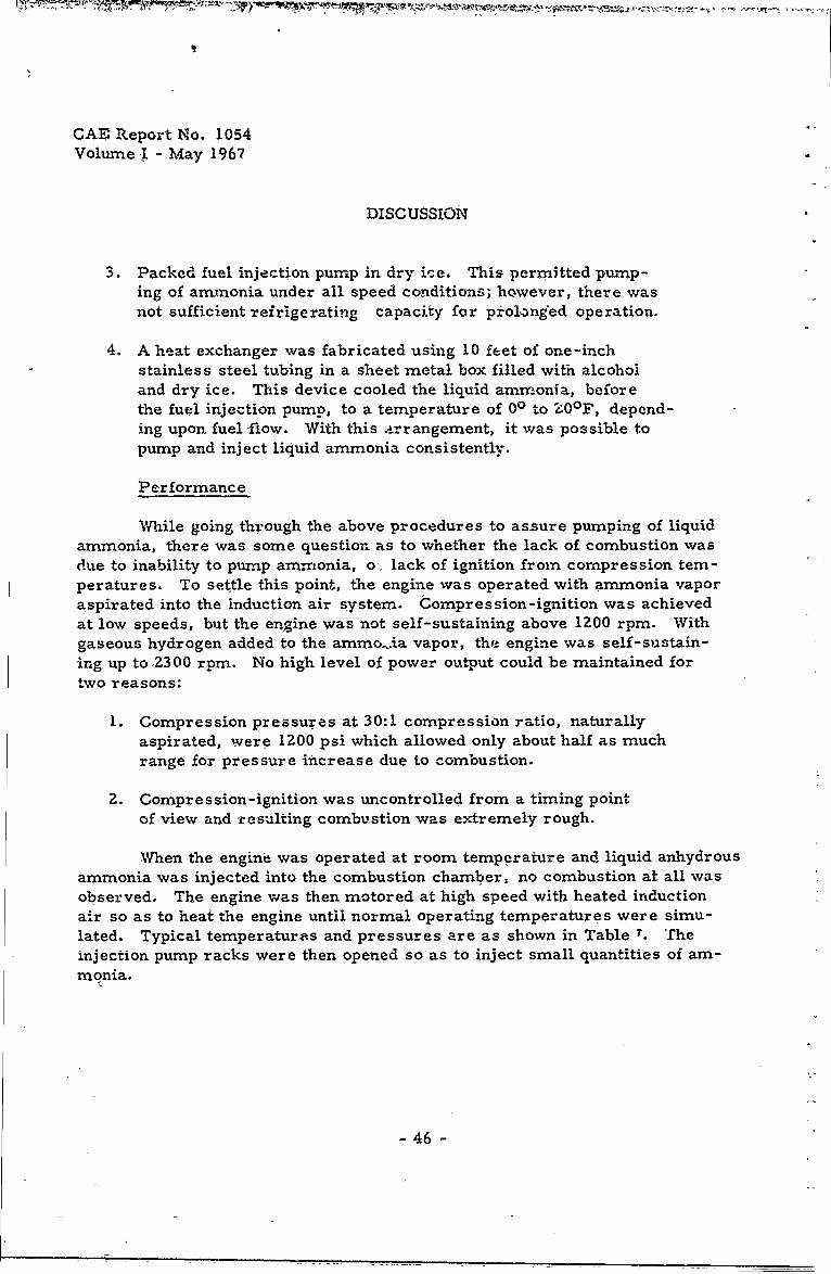
3. Packed fuel injection pump in dry ice. This permitted pump-ing of ammnonia under all speed conditions; however, there wasnot sufficient refrigerating capacity for prolnged operation.
4. A heat exchanger was fabricated using 10 feet of one-inchstainless steel tubing in a sheet metal box filled with alcoholand dry ice. This device cooled the liquid ammonia, beforethe fuel injection pump, to a temperature of 00 to ZO0 F, depend-ing upon fuel flow. With this arrangement, it was possible topump and inject liquid ammonia consistently.
Performance
While going through the above procedures to assure pumping of liquidammonia, there was some question as to whether the lack of combustion wasdue to inability to pump amrrmonia, o-. lack of ignition from compression tem-peratures. To settle this point, the engine was operated with ammonia vaporaspirated into the induction air system. Compression-ignition was achievedat low speeds, but the engine was not self-sustaining above 1200 rpm. Withgaseous hydrogen added to the ammo. ia vapor, the engine was self-sustain-ing up to 2300 rpm. No high level of power output could be maintained fortwo reasons:
1. Compression pressures at 30:1 compression ratio, naturallyaspirated, were 1200 psi which allowed only about half as muchrange for pressure increase due to combustion.
2. Compression-ignition was uncontrolled from a timing pointof view and -resulting combustion was extremely rough.
When the engine was operated at room temperature and liquid anhydrousammonia was injected into the combustion chamber, no combustion at all wasobserved. The engine was then motored at high speed with heated inductionair so as to heat the engine until normal operating temperatures were simu-lated. Typical temperatures and pressures are as shown in Table T. Theinjection pump racks were then opened so as to inject small quantities of am-monia.
- 46 -

CAE -Report 11o. £054.Volume I -. May 1967
I DISC USSION;
I TABLEI
TYPICAL OPEXATING CONDITIONS PIRT MOI NETO
1rpm 1000 1200 -1700 '1800 2000
'Manifold Pressure, "H A 31 3
g 3-i 343-43i~Manifold Temperature, F1'97 1_90 214 208 208
Cylinder Heat-Temperature,, RF 326 343 3 74 194 468,
0iTmertrO 182 182 1,86.1 -186 193
Cdompression Pressure, 1-i 1150 1250 1-300 1350 1300
5Exhaust Temperature,, OF -- 180 250, 228 '280
1Oni the -first -injec .ion, a -slight increase in cbylinder ,Oressure could be,observed, indicating~ that pkrt of the fuel charge was tzying to burh. Subsequent
'3 injections of aminonia., howeiver, refrigerated the combustion air to the point[ .wher e comhpr es sion pre ssure s were, lowered as much -as .250 psi. Ahalysis- ofthe indicatoi--card's indicates that cotln ression temperatures with k-amonia. in-jection were in-the neighborhood of LOOOPF, abou~t 200 degre belo h p
laneous, ignition, temperature of ammuonia. At this point, "the direct injectiont_Approieh appeared to be so irnpractical, that it Was. terminated, with the-advice,
Ian(!. consent of-theoi ATAC Project Engineer,.
J COMPP.ESSON.-IGNITION INVESTIGATION
Diesel Pilot eijction
IAn AVOS- 1790 Vee -Twin (a two -cylinder ver sion of- one b,!y of -the 1-cylnder tank engine) was installed in -Continental, Test Cell No. A -7. The en-
giewas equipped with the latest design pistons havinig a comoressioh ratio of
fuel injector s injecting -into dummy tanks, -from which the fuel could be i'etukrneid
-47-
CAE Report No. 1054Volume I -May 1967
DISCUSSION
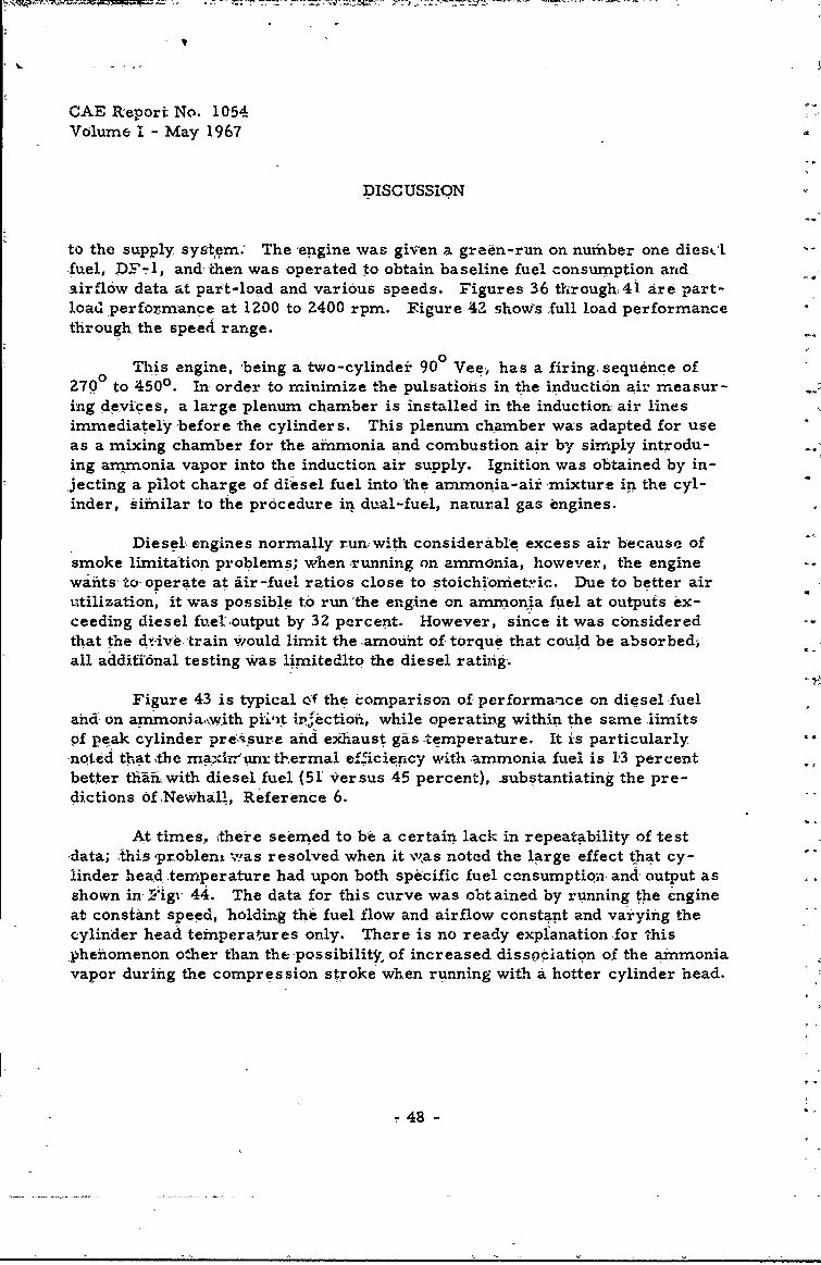
to the supply system; The 'engine was given a green-run on number one diescifuel, DF-1, and then was operated to obtain baseline fuel consumption andairflow data at part-load and various speeds. Figures 36 through4i are part-loatl performance at 1200 to 2400 rpm. Figure 42 show's full load performancethrough the speed range.
0 This engine, being a two-cylindei 90° Vee, has a firing. sequence of270 to 450° . In order to minimize the pulsations in the induction air measur-ing devices, a large plenum chamber is installed in the induction air linesimmediately 'before the cylinders. This plenum chamber was adapted for useas a mixing chamber for the aimonia and combustion air by simply introdu-ing ammonia vapor into the induction air supply. Ignition was obtained by in-jecting a pilot charge of diesel fuel into 'the ammonia-air mixture in the cyl-inder, similar to the procedure in dual-fuel, natural gas engines.
Diesel, engines normally run, with considerable excess air because ofsmoke limitation problems; when running on ammonia, however, the enginewants- to- operate at ir -fuel ratios close to stoichiometric. Due to better airutilization, it was possible to run 'the engine on ammonia fuel at outputs ex-ceeding diesel fueL'output by 32 percent. However, since it was consideredthat the dv .. -'train W/ould limit the amount of torque that could be absorbed,all additional testing Was limitedlto the diesel ratinig.
Figure 43 is typical of the comparison of performance on diesel ,fueland on ammonia,with pii,'t irectioft, while operating within the same limitsof peak cylinder pressure and exhaust gas temperature. It is particularly
pnoted that tbe matinrum thermal efficiency with ammonia fuel is 13 percentbetter tihwith diesel fuel (51 Versus 45 percent), substantiating the pre-dictions ofNeWhall, Reference 6.
At times, kthere seemed to bi a certain lack in repeatability of testdata; this 'problent v'as resolved when it w, as noted the large effect that cy-linder head temperature had upon both specific fuel ccnsumption, and' output asshown in Figr 44. The data for this curve was obtained by running the engineat constant speed, holding the fuel flow and airflow constant and vaiying thecylinder head temperatures only. There is no ready expianationfor thispheiiomenon other than the possibilitjr, of increased dissfociation of the ammoniavapor during the compression stroke when running with a hotter cylinder head.
48 -

FJ CAE Report No. 1054Volume I - May 1967
AVS-1?90 V-Twin, Pe~t Load Performance - Diesel Fuel Basekine Data - I0 P - 1.6:1 (.R.
8-Hole .2&=.I40 1ozzles - .084-Ich Z s - Ins. Ady'. 370 BTC
I30
135
.55
it .. ,,
40 6D eo 0 2o
E4 -PF .
£-49- Fig. 36

CAE Ruport No. 1054Volume I -- May 1967
07-155AVbS-17,90 V-Twin I
Part Load Performance - Diesel Fuel Baselixe Data - 1600 RPM - 18.6:1 C.R.8-11ole .276= 1400 ozzles - .084 -Inch Livea - Inj. Adv. 410 BIV
.65.
U I -I-0q
r S- -- - _-7" 0o______
I 5
.6o _.,._-_. \_... . .. .... ....
450 60 - . 1
BM- PSI
-so- Fig. 37

CAE ieport No. 1054Volume I - May 1967
1 H3 ,56AVD-1790 V-T'inPart Load Performance - Diesel Fuel - Pasellne Data - 1800 RI! 18.6:1 C.R,8-Hole .P76u 1400 Npzzles - .084-Inch Line - InJ. Adv. 43O BTC
.,4o- __ ___
a20-
10 -
700 8
.55
.50
BMEP -PSI
-51-Fig. 38

CAE Report No. 10S4Volume I - May 1967
1d57
AVDS-1790 V-TwinPart Load Performance - Diesel Fuel - Baseline Data - 2000 RPM 18.6:1 C.R.8,7ole .276 =a 1400 Nozzles - .084- Ih Lines - Inj. Av. 3° Cran.
.50
I _ _ _ _ _ _ _ _ _ _ _ _ I _ _ _ _60 80 100 120 10
-5- ZFig. 39

CAE Report No 1051Volume I - May 196"
AVDS -1790 V-TwirNPart Load Performance - Diesel Fuel - Basel'ne Data - 2200 RPM 18.6:1,C.R.8-Hole o27Ec 1400 3ozzles - .08-inch Lines - In3. Alv. 43? BT
55- 7_____
"" 25
! - __ 700
.50
U I
9! ~.45
.40-
4o 60 80 100 120 140
2MEP - PSI
-53- Fig. 40

CAE Report No. 1054Volume I - May 1967
NH3-2,59AVDS-1790 V-Twin
Part Load Perform ce - Diesel Fuel - Baseline Data - 24O RPWi8.6:XCR v8-Hole .276= 1460 liozzles - .084-Ich ULnes - i0. My. 430 BC
55
4,5
'5
1200
low
- - 100
.50
407 6D8 100 20 -70
BIHP - PSI
-54- Fig. 41

CAE Report No. 1054
Volume I - M,,ay 1967
* 1113-169
AMt-1790 V-TNinPerforinahce on No. 1 Diesel Fuel - Full Rack 18.6:1 C.R. Factcry AirSu,,ercbfrged - AVDS-1790-2A Injection Pump -8,276M 11400 11oz, .08U.' Linis.
BAEMEANEFFECTIVE PRESSURE
12~ - _1700
rI
PEAKl(X- -CLINER -L " . BRKE HOORSEP~rl1500
1100-
IT <
>4
7 ~ WO
£0 . _FUELIFLOW
30 FELM COSUPTO
- _ _ . = _ .

CAE Report No. 1054Volume I - May 1967
NH 3 -139AVDS.1790 V-Twin (18.6:1 CR)PRELIMINARY PART LOADCOMPARISON - 1800 RPM
-I 4 NH 3 VAPOR WITH DIESEL PILOT INJECTION
>4U 0---) DIESEL
5
66°0 ['
91
500(......
60 100 140 180 220 260
-56- Fig. 43

CAE Report No. 1054Volume I - May 1967
AVDS-1790 V-Twin
Influence of Cylinder Head Temperature On Specific Fuel Consumption &BMEP
Ammonia V-tpor Fuel With Diesel Pilot Injection - 1800 RPM - 18.6:1 -CRD. Hill
r
MANIFOLD PRESSURE 40 (In. Hg)
160 EQUIVALENCE RATIO .80
• , 150
0_
V..
140
0 90
1 +Z.
.85-
w
14 70 300 330 360 390
CYLINDER HEAD TEMPERATURE °F
-57- Fig. 44
I _ _ _

CAE Report No. 1054
Volume I - May 1967
DISCUSSION
Fuel Iniection Equipment
Early -in this program, it was recognized that for the pilot fuelapproach to be considered effective, the amount of diesel pilot fuel usedmust be held to an absolute minimum. When the fuel rack was backed out topump small quantities of fuel (less than 10 cubic millimeters. per stroke),first one cylinder, thenthe other, would cease firing. Investigations revealedthat the multi-cylinder pumps were not balanced at low fuel f' r conditions.American Bosch manufacturers of the fuel injection equipment, advised thattheir normal acceptable tolerance on these injection pumps was a variationfrom cylinder-to-c-ylinder of 7 mm 3 , much above the minimum it was anti-cipated could be attained. With this built-in imbalance, it was not possibleto lower the minimum pilot fuel at 1800 rpm below 11 mm 3 per stroke, e-,enwith optimizing the size and number of nozzle holes.
The multi-cyliander fuel injection pump was removed and replaced bytwo single-cylinder American Bosch, type APE-lBB, pumps with ine milli-piete. plungers. The pumps were carefully balanced by installing shims ,othat their plunger lift and port closing characteristics were identical. Aseries of modifications were made to the fuel injection system to improve theprobabilities of pumping minimum quantities of fuel. These modifications in-cluded the following:
1. injection line sizes were changed from 0.084 to 0. 055-inch I. D.
2. Zero volume retraction valves Were installed in the fuel injectionpumps.
3. The four holes in the fuel injection nozzles were successivelyreduced in diameter from 0. 276 mm to 0. 22 mm, to 0. 20 rmnm,to 0. 19 mrr.
Figure 45 shows the reduction in pilot fuel requirements versusnozzle hole size. Figure 46 shows the reduction in specificfuel consumption (ammonia only) versus hole size when operat-iig with a relatively constant amount es' diesel pilot fuel.
4. Reduced dead fuel volume in nozzle hold'er.
5. Lapped nozzle needle valves to increase operating clearance.
58-

CAE Retort Ho, 1054Volume I -May 1967
2073 2o7
AVDS 1790 V-Twin /13Effect of Nozzle Area on Minimum Pilot Fuel RequirementsWith 4 Hole Nozzles at 2400 RPM and 45" AUIXhP
1.2-:,
1.0
~k
- \4
0 .8
.7
G
. 160 .150 .140 .130 .120 .110
Nozzle Hole AreaSquare Millimeters
".22 .0 .19
No:zle Hole DiameterMillime ters
59 Fig. 4r
CI

CAE Report No. 1054Volume I - May i967
ML.3 208AVDS 1790 V-Twin #3Effect of Nozzle Hole Area on BSFC with 4 Hole Nozzles
at 2400 RPM and 45" A.IP
1.2 ".
'-4. t
I -,l .1 "
.910 -. .....-- .
~ .C9 -
.850
.: -- .8 3 0 -,,
-- I-.60 .150 .140 .130 .120 .110
Nozzle Hole AreaSquare Millimeters
.22 .20 .19
Nozzle Hole Diameter
Millimeter
-60- Fig. -16

'"AE Report No. 1054
Vohlrne I- May 1967
DISCUSSION
I With all of the above modifications, it was possi.le to operate the Vee-Twin engine using only 1. 8 mm 3 per stroke, or 0. 35 pou ds per hour of diesel
r fpilot fuel at 1800 rpm. Figure 47 is a chronological chart showing the variouschanges made and the reduction ii pilot fuel requirements versus time in weeks.
The reduction in pilot fuel &.ow was not without drawbacks. The small
quantities of fuel being pumped were not sufficient to keep the nozzles cool, re-
sulting in partial plugging of the holes and lacquering of the needle valves. Thiscould occur in as short a period as 15 hours of operation. Figure 48 illustratesthe effect of nozzle cleanliness on engine performance. To prevent collectingerroneous data, the fuel injection nozzles were removed and cleaned every rrorn-
ing before beginning the day's operation.
Manifold Pressure
The Vee-Twin engine was run at 1800 rpm to determine the effect of mani-1fold pressure. Figure 49 shows the effect of nan'fold pressure on diesel pilot
fuel, ammonia flow and load as expressed in indicated mean effective pressure.Optimum ammonia flow is a linear function of manifold pressure, as expected,
since the engine wants to run at a fixed stoichiometric ratio. Diesel pilot fuel.Srequirements, however, ary in an inverse fashion, increa%,ing rapidly at mani-fold pressures below 30 inches of mercury absolute. Betv.een 22 and 17 inchesmanifold pressure, the engine could carry no useful load, barely gtneratingsufficient power to equal its own parasitic losses. Below 15 inc!hes of mercuryIn -ifold pressure the engine was not self-sustaining, ue to long ignition lag.Figure '50 is a reproduction of the pressure-time diagrams at 1800 rpm for mani-fold pressures of 45 to 17 inches of mercury absolute. In all these runs, theoptimum fuel injection timing remained the same, bit the point of ignition was
I cofntinually retarded until at 15 inches manifold pressure there was no discerniblefiring The compression ratio was the same throughout, and theoretically thecompression temperatures would have been the same. The increased ignition
jlag is assumed to be due to the decreased density of the charge and the greaterdifficulty for a droplet of fuel to find a molecule of oxygen. This situati.on is simi-
lar to the results reported by Boerlage and Broeze in 1932, Referenced Item
Swirl
Induction air deflectors, capable of increasing or decreasing swirl 5n thecylinder, were designed and installed. Excessive swirlfhad a very definitedelet-erious effect as regards both fuel consumption and power output. Small
T amounts of swirl appeared to have little, if any effect. Swirl deflectors were no
1 - 61-LI

CAE Report No. 1054Volume I - May 1967
%,u 44IIrt,
'C
Z:f .+ : l
~~ I
-62. <:r,. 47
~I I
-6Z Ci ,4

CAE Report No. 1054Volume I - May 1967
AVDS-1190 Vee-Twin9Effect of N1ozzle cond.tion on performance with Anhydrous Amnonia Vaporand i.-i Pilot Fuel
0 After Cleaning Nozzle""60. 0 Before Clegang Nzzle
S I
~50
Ila
40 __
70.
RATIO
0.8
____ ____ ___ ____ _ - 0.7
0.6 0.'65 0.7 0.75 0.8 0.85
-I. ~-EUIVALENCEi0 RATIO
-63- Fig. 48
-I

CAE Report No. 1054Vqlume I - May 1967
F- NH3 -1 9 -AVDS 1790 V-Twin[ Effects 02 Manifold Pressure on Dieiel Pilot Fuel
R equirements and IMEP 1800 RPM1
5.0-
4.0-
33.5 -. .... ... .,-5 3.0-
2-.5 -'
2.0 ,
1. DF #1 FLOW
1.0-
0. r0
o: "\ -J I-NH3I 1C-FLOW
0 .. . IM~P 125 -40 ------- rJn
e:120 }-- ..
NO LOAD -450. .. rJ. ' . _ ,20 25 30 35 40 45
MiANIFOLD PRESSURJzINCHES HS Abs
-64- Fig. 49

I CAE Report No. 10543; Volume I - May.1967
3; INFLUENE OF MAN IFOLD PRESSURE - FEUEL NH3 VAPOR -
DWEEL PILCT1 INJECT=N -w V-TWIN 1790 - C.R. '18.6:13; 1800 RPMLANIFOLD PRESSYE "H9. ABS.
3;1400 4,
1200
Ii1000 22.1_ _
'C0.
L80Di 26.9___
6400
~40 02 OO 02 0003
C,,RANK ANGLE-DEGREES
I Fig. 50. Influence of Manifold Pressure on Indicator Diagrams.
4 -65-

CAE Report No. 1054Volume 1 - May 1967
DISCUSSION
Pilot Fuel Ignition Quality
An investigation was conducted to determine the effects of fuels havingvarious ignition qualities. CITE fuel having, - cetane number of 38, andDiesel Fuel No. 2, having a cetane number k 44, were substituted for DieselFuel No. 1 (cetane No. 50)-as pilot fuel for igniting the ammonia-air mixture.Neither CITE fuel nor DF-2 gave near the performarce obtained with DF-l.The problems were late ignition, loss of power, and inability to burn the samequantity of ammonia. With the lower ignition quality fuel, the engine demand-ed a much leaner fuel-air ratio
Pilot Fuel Quantity
Experiments were conducted to determine the effects of varying thequantity of diesel pilot fuel while holding all other variables constant Figure51 shows the results of this investigation. 1t is interesting to note that whenoperating at a desirable fuel-air raii (0. 85 equivalence ratio) the increasein output and reduction in specific fuel consumption (arnmonia only) are indirect proportion to the heat content of thd additional diesel pilot fuel. At aleaner fuel-air ratio (0. 64 equivalence ratio), the effect of increasing thediesel pilot fnel is quite drav -tic, indicating the necessity for much higherignition energy. The increas, in power output at the lower equivalence ratiois of the order of three times the heat content of the diesel fuel alone.
Optimum Performance
The AVDS-1790 Vee-Twin was run at constant manifold pressure andconstant speed, varying the fuel-air ratio to determine the optimum conditionsof operation. In order to ensure good ignition and combustion and comparableperformance at off -optimum points, the diesel pilot fuel was held at 4 to 5cubic millimeters per stroke. These tests wee repeated at various manifold'pressures and speeds to cover the complete load and speed range of the en -gine. Figures 52 through 56 show the results of these tests. In general,minimum specific fuel consumption is attained at an equivalence ratio of 0. 70to 0.75; whereas maxinurn output is attained at an equivalence ratio, of about0. 90. Increases in ammonia flow beyond this point, actually result in a losein power.
Figure 57 shows the envelopes of indicated specific fuel consumptionversus indicated horsepower for each of the various speeds. As would be
- 66 -

CAE Report No. 1054Volume I - May 1967
AVDS- 1190
k EFFECT OF VARIATION OF PILOT FRI. QUANTITY AT 1500 RPM AND TWO EQUIVALFNCERAT IOS
f '~.850 -EQUIVALENCE RATIO STOICHIOMF.TRIC AfiACTUAL A/F
50-4
70.
0
0.8
0.
0.
0 2J
PILOT FUEL FLOW #H
-67- Fig. 5

CAE Report No. 1054Volume I - May 1967
NH - 20 3
AVDS-1790 V-Twin #3
ISFC and Equivalence Ratio Vs. Indicated Horsepower
N 3 Vapor and Diesel Pilot Fuel @ 1200 RIS
! - 9quivalenee Ratio
Stoichionetric A/F Ratio
Actual A/F Ratio
Manifold Pressure) 30 in. Hg abs
32 in. Ug abs
A35 in.Rg abs
1'8
.7._
.700 .5
.580 ___________ _____
40 50 60 70 80 90
-I HP
-63- Fig. 5Z
V,

CAE Report No. 1054[ AVS-170 V-winVolume I - May 1967-H 201
ItFC and Equivalence Ratio Vs. Indicated 'Horsepower- - NH3 Vapor and Diesel Pilot Fuel @ 1500 RPM
0, Equivalence Rat ioStoichiome,ric A/P Ratio
Actual Al)? Ratio
Manifold Pressure _____
& .8
.70____________.
SGS
464
0.62
WI1
F
4,0 70 80 90 100 110
01T~m - I UPl
.1 -69- Fig. 53

CAE Report No. 1054Volume I - May 1967
N]I _ 2 0 4
AVDS-1790 V-Twin #3ISFC and Equivalence Ratio Vs. Indicated Horsepower
Vapor and Diesel Fuel @ 1800 RPM
____-_ _"- m m
- Equivalence Ratio IStoichiometric A/F Ratio
Actual A/F Ratio
x N1.0
Manifold Pressure0.
-32 in. g Abs
A - 35 in. ft Abs
0 - 40 in. Xg Abs
C3 45i.H Abs
0.8 0
_ _ 0.7
.72___ ___ 0.6
.64
60 80 100 120 140 160-0- TFg5
-70- Fig. 54

CAE Report No. 1054Volume I - May 1967
i3 - 202
AVDS-1790 V-Twin #3
ISFC and Equivalence Ratio Vs. Indicated HorsepowerNH3 Vapo" and Diesel Pilot Fuel @ 2100 RI
TJP
. i-d Pressure- Equivalence RatioMuenifold Pressure-
0 32 in. Hg Abs Stoichiometric A/F Ratio
35 in. 11 Abs Actual A/F Ratio
S40in. g Ab. 0" 3 45 in, Hg. Abs/
_0.8 C
-. .70 0.6
.66
- _____ Ill
7 8-.64
- .62
100 120 '1O 160 18020tullpVT - IhIP
764-784, 834-876 7 i.5-7-Fg.3

Volume I - May 1967
[ ~ ~AVDS 1790 IT-Twin #3 H-20
Indicated Horse-iower Vs. ISFC aldd Equivalencer ~Ratio Operated on NH3 Vapor and Diesel Pilot Injection 0 24U0) RM
IT,) Vanftedeit 12-23-66 Nov. 66-E= qulvalrance tli
Smichiouetrib A/F RctioIActual A/F Ratio
Manifold Pressure
O45 In. Hg Abs
o 40 in. Ng Abs
35~ in. Ug Abs 1A 32 in. Ng Abs
.730 .7 dow
Il
la 0
no1
Fig.--

-!-
CAE R1eport No. 1054Volume I - May 1967
l'13
v.'d.; '-:JO 7-lNin #/3
I,,r. Load P. rfor:rarnce ISFC vs IHP on NtI3 Vapor with Diesel Pilot. Qawn~i~es Approximote 4- 5 M4 3/ .kro~e 16.6:1 Citi
EN GINE SPEED. i RPt4
S- 1200
____~~~ 1_ _ _ _ _200
12100
LII
.1 k__ - -.
ji .--. ( ... ..- -- __
5 -7" Fg.5
:2 4
40 60 60 100 120 140 160 i80 PO0
Fig. 57-

CAE Report No. 1054Volume I - May i967
DISCUSSION
expected, the best fuel consumption occurs at 1200 rpm and the worst at 2400rpm. This is considered t be a reflection of the effect of the low flame propa-gation rate of arrmonia-air mixtures.
Spark -Ignition
The AVDS-1790 Vee-Twin was converted to a spark-ignition engine bydoing the following:
1. Removing the fuel injection pumps and installing an eight-cylinder Mallory "Super-Mag" Magneto. An eight-cylindermagneto was ,chosen in order to be able to obtain the 2700 -
4500 firing interval. The excess six leads in the magnetowere grounded out.
2. The cylinders were _emoved and the holes for the fuel in-jection nozzles were reworked to accept spark plugs. 12mmspark plugs were used as a matter of convenience and tominimize machining costs.
Three compression ratios (18.6:1, 16:1 and 1Z:l) were investigated inthe spark-ignition studies. Figures 58 and 59 show the combustionchimber shapes and the r:lative location of the fuel injection nozzles and thespark plugs, It should be noted that the longest reach spark plugs, consistentwith piston clearance, wer-e installed. No addition4l development was -inder-taken in this phase of the work; the best approaches developed under the L-141program were applied directly to this engine.
Spark Plug Gap
At each of the three compression ratios investigated, the spark pluggaps were varied to determine the optimum setting. Figure 60 shows theeffect of spark plug gap on brak.- specific fuel consumption. As is to be ex-pected, the optimum gap varies inversely with compression ratio. The opti-mum gap at 12:1 compression ratio, 0. 070-inch, is considerably less than the0. 100-inch at 12. 6:1 compresstion ratio required by the L-141 engine. Thereis no apparent explanation for this difference.
- 74 -

CAE Report No. 1054Volume I - May 1967
I
I Fig. 58. Sketch of 18. 61 Compression Ratio -Combustion Chamber Showing- A n- iectiort Nozzle.
-- '-75-
I

CAE Report No. 1054Volume I - May 1967
-7 2-
-'1300/
Fig. 59. Sketch of Spark-Ignition Combustion Chamber Showing Changes With
Various Compression Ratios and Location of Spark Pilug.
- 76 -

ICAE Report No. 1054Volume I - May 1967
AVDS-1790 V-Tvin #3Effect of Spark Plug Gap on BSFC at Three Compression Ratios.allory Marneto, Champion R-Series Plugs, 12 M,4 3/4" Reach
.95
.9. -_.94
• 93 '' [ Compression Ratio
a1nd Spark Plug Types
A 18.6:1 - R-115
.92 ] i6:1 - RY-Iol0 12.1 - R-120
I E~~.91 _ _
.89-i
I '
I I.87
.050 .055 .06o ,065 .070 .075
INCHES
-77- Fig. 60
I

CAE Reart No. 1054
Volume I - May 1967
DISCUSSION
Spark Plug Durability
The spark plugs used in this investigation were designed for use inconventional Otto cycle engines and were not intended for operation with thehigh firing pressures encountered in this diesel engine conversion. Whenrunning at 18.6:1 compression ratio and 32 inches of mercury manifold pres-sure, peak pressures of 1450 psi were experienced. As a result of thesepressures there we'-'e some failures due to internal gas leakage and to acutalphysical movement of the center electrode and it is porcelain insulation.Figure 61 shows two plugs that failed in this manner compared with an un-damaged plug. For this reason further testing was limited to naturally aspi-rated operation and no more failures were encountered.
Compression Ratio
Figures 62 through 74 showspecific fuel consumption and equivalenceratio at 18. 6:1, 16:1 and 12:1 compression ratio for speeds of Z00 to 2400rpm. Reducing the compression ratio from 18. 6:1 to 16:1 had slight effecton specific fuel consumption; it did, however, reduce peak firing pressuresby approximately 100 psi. Dropping the compression ratio still further to1Z:I did effect fuel consumption materially, particularly in the high speed-range, where an increase of six percent was observed. 'Figure 75 shows thevariation in firing pressures and specific fuel consumption with compressionratio at 18Q0 rtnn.
Performance Comparisons
Direct comparison of performance between operation using pilot fuelfor ignition and operation using spark-ignition is difficult because of thedifferent mode of testing. The compression-ignition engine using pilot fuelcould not be run with throttling of the induction air because of high ignitionlag. The spark-ignition engine, on the other hand, could not be operatedsupercharged because of the limitations on available spark plugs. Closeexamination of the data, however, does reveal the following trends:
1. With spark-ignition, actual ignition of the fuel begins about10 degrees earlier than with pilot ignition.
2. With spark-ignition, peak cylinder pressure is about 500 ptihigher and the = --ak pressure occurs about seven degrees earlier.
- 78 -

CAE Report No. 1054[ Volume I-May1967
0
4-3
0
0
T 0(IzHf>
ii:0k~4U3 i
al
0
79-

CAE Report No, 1054Volume I - May 1967
N13 - 222
AVDS 1790 V-TIUin ,,3ISFC and Equivalent Ratio vs Indicated Horsepower on N113 Vapor with
Mallory ilg., R-115 Plugs, Gap .055 °, 18.6:1 CR @ 1200 PM
A4
Equavalence RatioStoicliometric A/r Ratio 1.0
Actual A/F ratio
.78
Q .9
74 _ _.
.7
.72 __/ __
.1.6
.68"
Manifold Pressure . _ _,
.640 -30 in. Hg. ABS. 1IN0 -28 in. Hg. ABS. "-
0 -26 in. Eg. ABS.
.62 0 -24 in. g. ABS. I.___.._ _
Q-22 in. Hg. ABS.
.601 i j
30 40 50 60 70
IHP
-80- Fig. 6?

CAE Report No. 1054Volume I - May 1967
NH3 - 223AVDS 1790 V-Twin #3
IS-kC Ond Equivalence Ratio Vs. Indicated Horsepower on NH3 Vapor with
Mallory Mag., R115 Plugs, Gap.055' 18.6:1 CR @ 1500 RPM
- Equivalence Ratio
Stoichmetkic A/F Ratio _ ___---1.0
Actual A/ Ratio
i L4 1.. .9
/ , I EI
"_ _ _ i ,
'* .70-' ;
s~.9
~~.8
II.6
. I.68 i.
..
.64
i ; Manifold Pressure
0- 30 in. Hg. ABS.62 -28 in. Hg. .BS.
if - 26 in. Pg. ABS.
1- 24 in. Ug. AES.
- Q - 22 in. 11g. ABS.
40 50 60 70 80 90 100
: ,,iIHP
-81- Fig. 63~-81-

CAE Report No. 1054Volume 1 May 1967
NIl3 - 224
AVDS 1731, V-Twin #3
ISFC and' Equivalence Ratio Vs. Indicated Horsepower on NH3 Vapor withMasllory Mag., !R-115 Plugs, Gap .055" 18:6:1 CR @ 1800 RP
Equivalence Ratio
1.0 ' Stoichiowetric A/F Ratio1.0 Actual &,'F Ratio ..
Manifold Pressure
0 -28in. 11g. ABS - I-" 26 in. 11g. ABS,
- 24 in. Yg.ABS.
.8 Q-22 in. Hg. AS. __/
.7/ . +
.68 ....
.6
.64 - , ..
.62 o1
.6o .
50 60 7u 80 90 100 110 120
.ip
- 8Z-Fig. 64

CAE Report No. 1054Volume I - M:-y 1967
AVDS 1790 V-Tin 3
ISFC and Equivalence Ratio Vs Indicated Horsepower on NH3 Vapor wit,Mallory Mag. R-116 Plugs, Gap .055" 76.6:1 CR @ 2100 RPM
-. Ii. VanSweden
SEquivalence RatioStoichisetric A'F Ratio __
f .Acttual A/F Patio
I I'
• .8 -...----..-
I6 0'['
8Manifold Pressure30 in. Jig ABS ft
C 20 in. Hig ABSI- 6 in. If ABS
Gr- - 24 in. Jig ABS . , ._ ,..__ _. _ __
__ -22 in. fig ABS 0,- 20o i,.Hg, t ,', * I .9 '-
.64 -. . *
.,~ ~ ~~6 --- i r.-.
\ [ ."' I
.60
,,I i I
.58
70 80 90 100 110 120 130 140
II1P
-83- Fir. 65I-83-

CAE.Report No. 1054 IVolume I - May 1967
AVDS 1790 V-Twin #3ISFC and Equivalence Ratio Vs. Indicated Horsepower on NH3 Vapor with
Mallory Mag. R-116 Plugs, Gap .055" 18.6:1 CR § 2400 RPM
' r -... . . T - -
Equivalence Ratio
Stoichiometric A/F Ratio1.0 Actual N/F Ratio
.89"
.7 Manifold PressureI1.- 30 in. Hg ABS- 28 in. Hg ABS
" - 23 in. lig ABS
S2 23 in..A3S
.66
, ~ ~~.62 • -
90 100 10 120 130 140 150 160
: : IHP
Fig. 66-84-

CAEReport No. 1054Volume I - Mvay 1967
103 - 227AVDS-1790 V-Twin
ISFC and Equivalence Ratio vs. Indicated Horsepower on NH3 Vapor withallory Mag., R-120 Plugs, Gap .065", 16:1 CR @ 1200 RPM
-Equivalene Ratio
Stoichiometric A/F Ratio - OActual A/F Ratio
09
.1.6
.- .7
.666
.66 4__
-6 Manifold Preasure0 30 In.- Eg- ABS.o28 In. Hg. ABS.
____ ____ O" 26 In. Hg. ABS..60 2, Tn. Hg. ABS.
.__ o 22 in.HRg~.
85- . Fig. 67
I/

CAE Rtport No. 1054Volume I - May 1967
AVS-1790 V-Twin #3 NH3 228
ISFC and Equivalence Ratio vs. Indicated-Horsepower on lIH 3 Vapor withiMallory Mg.., R-120 Plugs, Gap .065", 16:1 cR @ 1800 RPM
- I fI( -Equivalence Ratio
Stoiehiometric A/F Ratio - 1.0
Actual A/F Ratio 1
.9-76-.76
..7
.72 - - _
.6
.70 - _ -
.68-
.66-
0) eManifold Pr-ssure
-_o30T . i. ABS..62 0 - 28 In. HG. ABS.
.20- 26 in. HG. ABS,S- 24 Tn. HG. Ams.
o . 22 I-. M. ABS.50 AI - !60 70 80 90 o 13.0 120
I HP
-86- Fig. 68

CAE Report No. 1054Volume I- May 1967
AVDS-1790 V-Twin 3 3
ISFr, and Equivalence Ratio vs. Indicated Horsepower on NH3 Vapor withMallory Mag., R-120 Plugs, Gap .065", 16:1 CR f 240 RPM
" I I I I I -
Equivelane w.eatioStoichiometric A/F Ratio -1
Actual AIF Ratio
* Manifold Pressure
__ h -30 In- HG. ABS.
-C-
-28 Tn. HG. ABS.
~ 26 in, fG. ABS.-- 24 In. 1IG. ABS.- 22 In. HG. ABS.
46S90 1_o0 11o 1 130 140o 10o 16o
-87- Fig. 69
j

OiCSE Report No. 1054Volume 1 - May 1967
NH3 2 30AVS-1790 V-Twin #3ISFV and Equivalence Ratio vs. Indicated Horsepower on NH3 Vapor with
Mallory Mag., R-120 Plugs, Gap .070", 12:1 CR @ 1200 RPM
- Equivalence RatioStoichiometric A/F Ratio 1.0
Actual A/F Ratio
] WA-4---.9
-. 8
.7
.6
Manifoid Pressure
•7C - - 30 In. HG. ABS.0 - 28 In. HG. ABS.O- 26in.HG. Aw.
0 - 24 In. HG. ABS.I_ .T . - (- 22 In. HG. ABS.
. .I I I -
30 40 50 60 70 80
-88- Fig. 70
-i

CAE Report No. 1054
Volume I - May 1967
NH3 - 231
AVD-1790 V-Twin #3ISFC and Equivalence Ratio vs. Indicated Horsepower on NH3 Vapor with
Mallory Mag., R-120 Plugs, Gap .070", 12:1 CR @ 1500 RBFMH. Van Sweden
-) - Equivalence RatioStoichiometric. A/F 4atio 1.0
Actual A/F Ratio
.76 .84
. .7- .7
I -'
jj : .7' .6
.72 6
-70-.66 .
30. In HG .7B "
0- 28 In. HG. ABS.
I li
-89n Fig. 71
-89-6z. G AS

CAE Report No. 10541Volume I - May 1967
AVU-1790 V.Twin #3 NH3 -232
ISMO and Ectuivalence Ratio vs. Indicated Horsepower on NiH3 Vapor with
Mallory Mag., R-120 Plugs, Gap .070", 12:1 CR @ 1800 RPM 1Equival~ence Ratioj
_______Stoichiometric A/FRatio 1.0Actu&I A/F Ratio
_____ _ __ ____.9
7?k~ _ .7 *
-.. 6
.7-
'Flanifold Pressure*-30n -HG- ABS-
________0 28 In. HG. AMS..6h -26 in. HG. ABS.
-24~ in. Hr.. ABS.
O22n. HG. ABS.
60 70 80 90 100 110 120
I lip
-90- Fig. 72

F'AVD-1790 V-Twin 113 R-23
ISFO and Equivalence Rati~o vs.* Indicated Horsepower on L7'3 Vapor withMallory Mag., R-120 Plugs, Gap .070V', 12:1 CR @ 2100 MP~
-Equivalence Ratio
10Stoichiometric A/F Ratio____
Actua1 A/F Ratio
.7 - _ _ _ _ _ _
Manifold Pressuz,
0 - 30 in. Hr.. ABs.0 - 28 In. liD. ABS.
OL 0 - 26 In. WG. ABS.0- 24i In. MG. ABS.
0.22 In. HG. AB3.
'.72 - _
.700
.681
t .66
70 80 90 100 UO0 120 130
IBF
-91- Fig. 73

CAE Report No. 1054Volume I - May 1967
NH3 234
AVD-1790 V-Twin #3ISFM and Equivalence Ratio vs. Indicated Horsepower on NH3 Vapor with
.1allory Vag. R-120 Plugs, Gap .070", 12:1 CR @ 2400 RPM1
4- Equivalence RatioSt Stoichiometrc A/f Ratio
Actual, A/P Ratio
.9. - .. -.8 d -
Manifold Pressure
o - 30 In. HG. ABS.0-28 n. HG. A ,,.O-26 in. HG. AB3.
Q-24 In. HG. ABS.
o -28 In. 1B. A.
.,1
90 100 1-o 120 130 ll 150 160
F HP
-92. Fig. 74

CAE Report No 1,054Volume I - May 1967
£ NH3-237AVDS 1790 V-Twip #3Effects of compression ratio on ISFC and Peak Pressures at optimum ISFC points
-va- manifold pressures @ 1800 RPM.H. VanSweden
Ta.,; 1200
T M. I]" 1000-
~1 800
60060O
100
1 90-
I80
II 70.60
COAIRESSION RATIOS
L 18.6:1
I .64 1 2:1 ,
I .62
.60
2"2 24 26 28 30
HANIFOIZ PRISRE
I'I$HES Hg. ABS.
-93- Fig. 75

RCAE Report No. 1054Volume I - May 1967
DISCUSSION
3. Horsepower output is greater with spark-ignition than witheither pilot ignition or straight diesel operation. It is possibleto obtain supercharged diesel output with unsupercharged am-
4. Neither compression ratio nor ignition source appears to have
awl significant change in the equivalence ratio at which eitherbest fuel economy ox: best power is obtained.
5. Figures 32 and 76 show brake specific fuel consumption mapsof the four cylinder, 3-7/8-inch bore L-141 engine andthetwo cylinder, 5-3/4-ifich bore 1790 engine. It is readily ap-parent that the large bore is no handicap in operating with am-robnia fuel; in fact, there is a considerable improvement infuel consumption with the larger cylinder. This may well bedue to the more concentrated combustion chamber and the morecentrally located spark plug.
6. The spark-ignition engine has inherent advantages over thepilot fuel engine; namely its ability to run throttled at part-load, no need for a secondary fuel, and more reliability of theignition source. Development of fuel injection systems forhandling extremely small quantities of pilot fuel could eliminatethe last item.
ADDITIVES
A subcontract was let to the Research and Development Departmentof American Oil Company in Whiting, Indiana, to investigate the effect ofchemical additives to promote ignition and combustion of anhydrous ammoniain both spark-ignition and compression-ignition engines. To provide infor-mation on the afnmonia combuitibn process and thds on"the inie'chanisn" ywhich an additive might function, a bench react6r was devised which wouldfacilitate the measurement of the ignition temperature and level of oxidationof a mixture of ammonia and bxygen, or ammonia and 'xygen plus an additive.
Selection of Additives
Additives were selected according to possible use with ammonia inspark-ignition engines and in compression-ignition engines. For spark-ignition engines, the primary interest was in gaseous additives which could
- 94 -

CAE Report No. 1054Volume I - May 1967
AVS 1790 V-Wir - 239
Fuel Consumption Map - Performance on NH3 Vapor with Mallory Magneto,
R-115 Plugs, Gap .055" 18.6:1 CR
T7 1"He3 Maximum
1 10
-
10
I-
I __ _____
I T.esel aximrng seline blIP
I:r
IT601 V__
20 01018020210
MIGINE SPEED
R.P.M.
95:; Fig. 76

CAE Report No. 1054Volume I - May 1967
DISCUSSION
be introduced with gaseous ammonia, although some liquid additives wereconsidered. For compression-ignition engines, the primary interest was inadditives that might be effective at low concentrations and that would be solublein liquid ammonia, although gaseous additives were also considered for in-troduction via the intake air.
Bench Tests
Eight gases and two liquids were tested in the bench reactor as ad-ditives for spark-ignition engines. Two of the gases, hydrogen and ozone,appeared to have a strong effect on the oxidation of ammonia, whereas theremainder had slight or no effect. Both liquids, hydrocarbons, had strongpositive effects on oxidation of ammonia. The scope of work on additivesfor spark-ignition engines was limited because the favorable performance ofhydrogen and acetylene was well known.
A total of 45 additives were tested in the bench reactor as additivesfor compression-- ignition engines. All were considered to be soluble inliquid atLumlnia, and several were tested at various concentrations. Of thistotal, on typhnic acid, was found to induce ignition at concentrations aslow as 0.. - percent by weight of ammonia. Six additives at one-half percentsubstantially reduced ignition temparatures as did six additives at 1.0 per-cent, two at 1. 5 percent and four at 5. 0 percent. Although not inducingignition, 11 additives at 5.0 percent, or less, significantly increased the oxi-dation of ammonia.
ENGINE TESTS
Ten gases and 14 liquids were tested as ammonia additives in thespark-ignition CFR engine at 900 and 1800 rpm and 8. 0:1 compression ratio,35 degree spark advance and best power air-fuel ratio. Engine performanceon ammonia only and on hydrogen only was checked first for reference pur-poses. Of the gases, hydrogen was by far the best additive, permitting fairlygood engine operation at 900 and 1800 rpm at concentrations of less than 1. 5percent by volume. Acetylene was next best, requiring about six percent togive. good engine operation at both speeds. The liquid additives, althoughseveral permitted good engine operation at both 900 and 1800 rpm, all re-quired use of unreasonably high (over 10 percent) concentrations.
-96-

CAE Report No. 1054Volume I - May 1967
[ [ DISCUSSION
Compression-ignition engine tests consisted of an evaluation of the per-
formance of gases added to the intake air, and of several liquid-ammonia addi-tives selected from the bench reactor prograrr. The work on the inducted gaseswas conducted first, to simultaneously evaluate the gases as ammonia additivesand pinpoint the best engine operating conditions to use for evaluating the liquid-
i[ ammonia additives.
Of gases added to the intake air whilc ammonia was being injected, hydro-gen, normal butane, and acetylene all facilitated combustion at some engineoperating condition. The gases generally were tested -at 20:1, 25:1 and 30:1compression ratio, and at 900 and 1800 rpm. Comb ustion with ammonia and
1' hydrogen was achieved at 25.1 and at 30.1 compression ratio at both 900 and 1800rpm, performance improved as either compression ratio or speed was increased.Combu.sion with ammonia and normal butane was achieved at all compression
" ratios and speeds (not tested at 30:1 cr and 1800 rpm), but butane consumptionwas excessive at 1800 rpm. Combustion with ammonia and acetylene was a-chieved at 20:1 and 25:1 cr and 900 and 1800 rpm (not tested at 30:1 cr). Per-
formance improved as either cpmpression ratio or speed was increased.
The additives selected from the bench reactor program were engine testedat Z5.1 cr and 900 rpm, the condition where all inducted gases performed most
similarly. Of the ' non-explosives", ammonium nitrate was tested at concen-
trations of '. 0 and 5. 0 percent of an additive-liquid ammonia rn-.xture, and am-monium perchlorate was tested at 1. 0 percent. Styphnic acid was selected as themost effective "explosive" and was tested at 0. 1 percent. During the testing ofthese additives, the engine was closely observed for any evidence of the additiveaffecting combustion, and was checked "or fire-ability by bracketing runs on theadditives with runs using inducted acetylene. All of these liquid-ammonia additivesproved to be c.ompletely without discernible tendency to initiate combustion of
r• ammonia in this engine.
A detailed report of the additive investigation, including curves, tablesand photographs is included as Appendix I of this report.
FLAME TUBE TESTS
it was originally intended to evaluate the most promising additives uncover-ed in the investigation by AMOCO 'by running flame stabilization tests in the Allisonflame tube. Prior to the completion of AMOCO's investigation, Continental author-ized lison to conduct screening tests on three oxides of nitrogen, carbon mon-oxide, aminonium nitrate and hydrogen peroxide. All oI these materials exceptcarbon monoxide were potentially producible in the field by the Energy Depot con-
j cept. Since the results from AM/iOCO did not produce any practical additives
97 -

CAE Report No. 1054Volume I - May 1967
DISCUSSION
other than hydrogen (which can be produced by partially dissociating ammonia)this list was never augmented.
For this screening effort, all gaseous additives were checked at aconcentration of five percent by volume of fuel flow. Stable burning was es-tablished and the fuel and additive flows adjusted to the desired test condition.The air -flow rate was then increased or decreased until blow -out resulted.
The results of these tests are summarized as follows:
1. In five percent volumt, none of the additives tested increasedthe apparent ammonia-air flame propagation velocity to thedegree obtainable by dissociating 28 percent of the incomingammonia fuel (five percent-hydrogen by weight).
2. The beneficial effect of carbon monoxide and the nitrogenoxides are very dependent upon the local fuel-air ratio of theammonia - air mixture.
3. Nitric oxide, NO, appears to offer the most promise as aflame propagation rate improver over the full equivalenceratio range of 0.9 to 1. 2. However, it did not significahtlyexceed the effect of five percent acetylene additions at anymixture ratio. Also the formation of solid deposits resultingwhen the additive vapor in air mixed with the ammonia fuelcould render its engine application difficult.
4.. Carbon monoxide, CO, provided significant improvement tothe ammonia - air flame propagation rate at lean air-fuelratio (0. 9 stoichiometric), but was ineffective at fuel-richconditions.
5. Flame stability limits were extended considerably at fuel-rich( > 1. 1 of stoichiometric) conditions by nitrogen dioxide, NOaddition, but the benefits were insignificant in the stoichiometricrange. Undesireable solid deposits were also experienced withthis material.
6. No conclusive results could be obtained as to the effect of am-monium nitrate additions due to injection and mixing problemsinherent to the test burner system-
- 98 -

CAE Report No. 1054Volume I - May 1967
DISCUSSION
A detailed report of the investigation of the stable burning limits of am-f monia - air flames, including sketches and graphs, is included as Appendix II
of this report.
IONIZATION
ifl It had been shown in previous work that the combustion of ammonia-airmixtures could be initiated by spark devices. Ordinary spark devices, however,operating in pure ammonia and air mixtures left much to be desired, since the
Senergy they made available was marginal for ignition. The purpose of this studywas to learn whether or not high-energy line discharge by the longest possiblepath could alleviate these problems.
It was first assumed that if many times the minimum ignition energy were
available, ammonia decomposition would (on a sufficiently large scale) result inthe realization of better burning properties. Secondly, it was assumed that ifmuch of the volume of the chamber were to be affected by ionization due to thedischarge, rather than by the point source presented by a spark plug, that the
Il low flame speed of amrmonia would not necessarily be a critical consideration.
* The investigation was conducted by means of a laboratory pulse generatorwhich discharges its high energy by means of electrodes mounted in a "bomb"chamber containing controlled mixtures of ammonia and air at various pressuresand temperatures.
I. Test Program. In order to test the pulse generator, atrmosphericdischarges with varying arc lengths were tried. Spectacular arcsup to 10 inches in length were drawn, Fig. 77. When of any lengthin excess of about four inches, the arc is not confined to a singlemain bolt, but rather is spread to many fine tendrils following thelines of the electric field.
A series of "open-air" observations was made with the electrodesmounted in the head plates to determine the path of the arc. Astrong tendency to "short-cut" through the head plate was noted.
An effort was made to use hydrocarbon fuel, in the form of gasoline,for reference and calibration. Difficulty in controlling the air-fuelratio and the degree of vaporization rendered this approach im-Ipractical, and hydrogen was used for check-out and calibration.
'1 - 99-

CAE Report No. 1054Volumne I -May 19b7
Fig. 77. High-Energy Pulses Discha"~ging in Air.,
-160
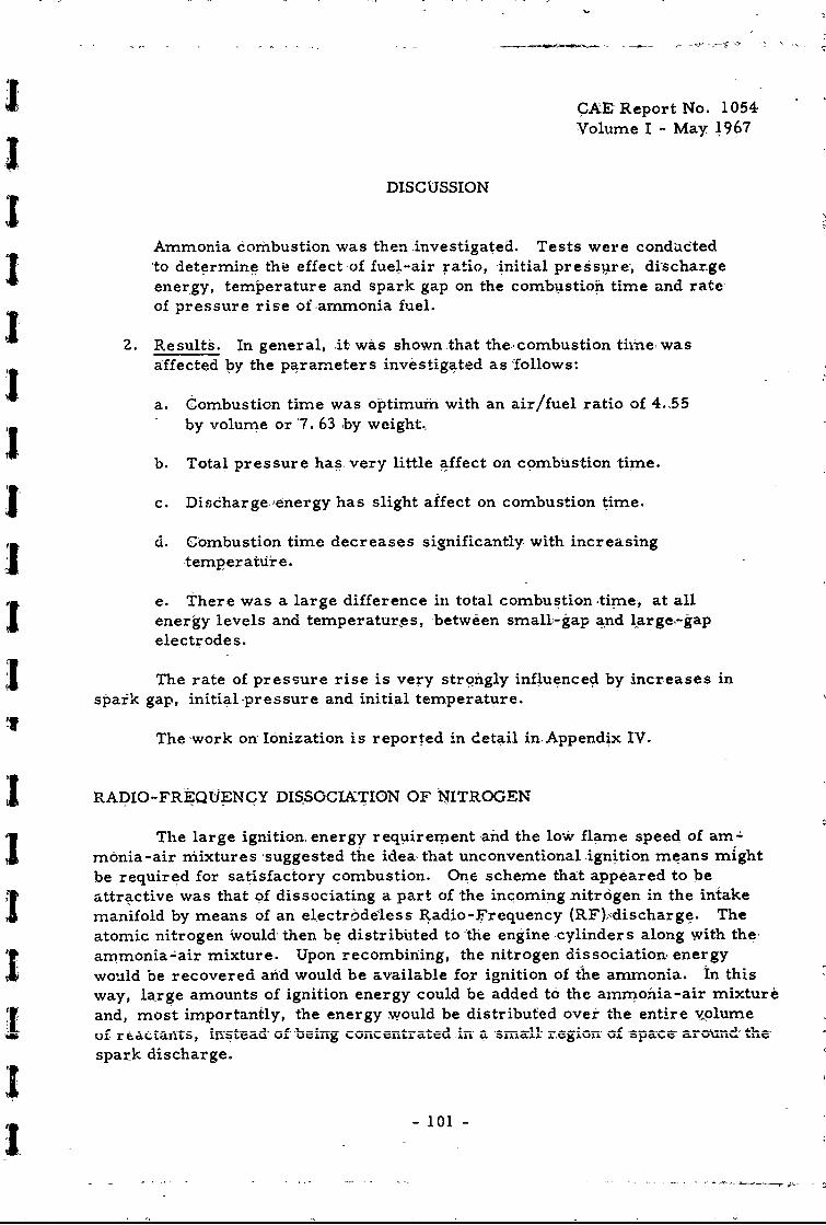
CAE Report No. 1054Volume I - May 1967
DISCUSSION
Ammonia combustion was then investigated. Tests were condaetedto determine thi effect of fuel-air ratio, initial pressure, dischargeenergy, temperature and spark gap on the combustion time and rateof pressure rise ofammonia fuel.
2. Results. In general, it was shown that the' combustion time, wasaffected by the parameters investigated as follows:
a. Combustion time was optimum with an air/fuel ratio of 4..55by volume or 7. 63 by weight.,
b. Total pressure has. very little affect on combustion time.
c. Disdharge,,energy has slight affect on combustion time.
d. Combustion time decreases significantly with increasing-temperatir e.
e. There was a large difference in total combustion time, at allenergy levels and temperatures, between small-gap and large,-gapelectrodes.
jThe rate of. pressure rise is very strongly influenced by increases inspaik gap, initial-pressure and initial temperature.
The work on" Ionization is reported in detail in Appendix IV.
RADIO-FREQ1UENCY DISSOCIATION OF NITROGEN
The large ignition energy requirement and the lo- flame speed of am-monia-air mixtures 'suggested the idea, that unconventional ignition means mightbe required for satisfactory combustion. One scheme that appeared to beattractive was that of dissociating a part of the incoming -nitrogen in the intakemanifold by means of an electrodeless Radio-Frequency (RF).discharge. Theatomic nitrogen Would then be distributed to 'the engine ,cylinders along with the.ammonia-air mixture. Upon recombining, the nitrogen dissociation, energywould be recovered arid would be available for ignition of the ammonia. In thisway, large amounts of ignition energy could be added to the ammonia-air mixture
and, most importantly, the energy would be distributed over the entire volumeuf r ictats, 11 d of-bain-g ....... '... Q.LLC6A .L ...I . . kL=. _-
spark discharge.
I- 101 -

CAE Report No. 1054Volume I - May 1967
DISCUSSION
Before building any hardw Lre or initiating any experimental tests, itwas decided! that theoretical calculations should be made to determine:
1. The time scale of the nitrogen recombination as a function oftemperature and initial atomic nitrogen density.
2. Significant effect of the presence of oxygen on the time scaleof the recombination.
These questions have been examined by solving appropriate sets ofdifferential equations that express the rates at which the various chemicalreactions proceed.
Results
Recombination of atomic nitrogen to molecular nitrogen takes place atan extremely rapid rate; for example, under typical conditions (standardtemperature and pressure, 10 percent dissociation) approximately 99 percentof the nitrogen, has recombined in less than 0" 1 millisecond. It would appear,because the majox part of the recombination will occur before the dissociatednitrogen reaches the engine cylinders, nitrogen dissociation is not % reliableignition source.
A detailed report of the RF dissociation investigation, including curves,tables and photographs is included as Appendix IV of this report.
RADIO-FREQUENCY DISSOCIATION OF AMMONIA
In developing a means of operating engines using anhydrous ammoniaas a fuel it was determined that performance of the spark-ignition engine wasenhanced considerably (particularly at the high-speed end) by the addition offree hydrogen to the fuel-air mixture. One method of obtaining free hydrogenis by the thermal dissociation of ammonia. Experience with thermal dissoci-ation, as reported above, has shown that operation is satisfactory when suf-ficient hydrogen is generated. However, during starting, low load and certaintransient conditions, the production of hydrogen is insufficient. It was there-fore determined that an investigadon of other means of dissociating ammoniawas in order.
- 102 -

, ICAE Report No. 1054
Volume I - May 1967
DISCUSSION
Analytical studies were initiated at Stevens Institute of Technology to
establish the feasibilitr of ammonia dissociation by use of radio frequency (RF)energy. A literature survey relative to RF dis-sociation of ammonia was con:ducted to determine the reaction kinetics and rate coefficients. MathematicalImodels of the reaction system were established and sets of equations were solved
by use of a high-speed digital computer. Since the reactioxs are temperaturedependent, solutions were obtained at 00, ZO, 500 and 1.000 centigrade.
IThe results of this study indicate that RF dissociation of ammonia isimpractical since the energy required to generate one-half Uf one percent hydro-
' Igen would require approximately 50 percent of the engine output. A detailedreport of the investigation of RF dissociation of ammonia, including curves and
tables, is included as Appendix V of this report.
MATERIAL COMPATABILITZ
In only one case in the performance of this contract was any part adverselyaffected by the use of anhydrous ammonia as a fuel; copper spark-plug gaskets,installed in the engine as delivered, completely dissolved after a very shortperiod of operation. Soft iron gaskets were used as replacements and no furthertrouble was encountered.
Figure 78 shows typical deposits found on the piston pin crowns. Analysis
of the deposits showed they consisted primarily of carbonaceous organic matterand oxides of barium, phosphorus and sulfur leading to the conclusion that theywere formed from oxidation of the lubricating oil. The piston skirts, Fig. 79,
were clean and in excellent condition.
Figures 80 and 81 show the condition of the connecting rod and main bear-ings after 297 hours of operation with ammonia fuel. It ic interesting to notethat the ammonia did not attack the copper in the copper -lead bearings nor in thealuminum piston alloy.
are vulnerable to attacks by ammonia, and these items should be replaced by
iron or other suitable materials.
-103-

CAE Report No. 10543[ Volume I -May 1967
1041

CAE Report No. 1054
[I Volume I -May 1967
0
LIn
I;;
0
4
-105-

CAE Report No. 1054Volume I -May 1967
Fig. 80. Connecting Rod Bearings After 351 Hours Of Operation, 297 HoursOn Ammonia. (D-341Z1)
Fig. 81. Main bearings after 351 Hours Of Operation, 297 Hours AnArnronia. (D-34122)
- 106 -

i CAE Report No. 1054
Volume I - May 1967
DISCUSSION
CONCLUDING REMARKS
T The results of this investigation have shown that it is indeed feasible andpractical to convert and operate both spark-ignition and compression-ignitionengines with anhydrous ammonia fuel. Whether or not such a fuel can be justified
T from either an econonic or military point of view is another question. From theprice aspect, ammonia costs approxir- ately ten times as much as hydrocarbonfuels for the same amount of energy, vhen both are bought in bulk quantities andtax free. It therefore becomes apparent that ammonia would never be used ifadequate stocks of hydrocarbon fuels were readily available.
There are however two situations, resulting from military operations,wvhere very strong cases can be made for use of anhydrous ammonia as a fuel.First is the strictly military situation in remote areas where supplying daily
.j requirements of hydrocarbon fuels is an extremely difficult and highly expensiveoperation. Under these conditions, use of a fully developed Mobile Energy Depotfor local generation of ammonia fuel would appear to be a logical and practicalsolution.
The second situation also results from military operation; when a localcondition exists where the military, as a matter of expediency, has appropriatedall existing stocks of hydrocarbon fuels, leaving nothing for use by the civilianeconomy, as happened in France and Belgium under German occupation duringWorld War II. If this situation should be repeated in the future in a friendlycountry, or in'the United States itself, due to loss of overseas sources of pe-troleum products, the ability to cperate civilian vehicles on ammonia could makea tremendous contribution to the war effort.
Commercial sources of ammonia that could be diverted for this purposehave been expanding rapidly in recent years. Chemical Economics Handbook,Reference 8, shows a total synthetic ammonia capacity for the 6ontinental United
1 ~ States for the following years:
January 1, Thousands of short Tons NH 3
1964 7,838.31965 8,595.0
1566 10,540.81967 15,092.8
1968 17,246.1
-1
~- 107 -

CAE Report No. 1054[Volume I - May 1967
KDISCUSSIONThis report has shown methods of converting existing compression-
ignition and spark-ignition engines to operate successfully using anhydrousammor *a as a fuel. It is considered that even bettex performance could beobtained from an engine that was specifically designed for operation on am-monia. Such an engine should embody at least the following design features:
1. It should be a spark-ignition engine utilizing a high energyignition source, such as a magneto.
2. It should have a relatively high, compression ratio of the orderof 12:1 to 16:1.
3. The combu~ticG chamber should be highly compacted, approach-ing a sp herical shape.
4. Spark plug design should be of an extra long reach type so asto locate the spark gap near the center ofmass of the com-bustion chamber.
5. A mild d;!gree of supercharging should be provided to ensure agood horsepower to weight ratio.
6. Compone-its should be designed to operate with peak cylinderpressures of at least 1200 psi.
7. if engine size is such that the rated speed will exceed 3000 --
rpm, a dissociator to provide up to 1. 5 ,percent hydrogenshould be used.
- 108 -

CAE Report No. 1054Volume I - May 1967
IREFERENCES
I 1. "Energy Depot Concept", SAE Publication SP-Z63 presented at;I SAE International Congress, Detroit, January 1965.
2. G. S. Samuelsen, "Flame Propagation Rates in the CombustionI of Ammonia. " University of California, Institute of Engineering
Research, Report No. TS-65-4, September 1965.
3. W. L. Buckley and H. W. Husa, "Chemical Engineering Progress",
pages 58 through 84 (196Z).
4. F. J. Verkamp, M. C. Hardin and 3. R. Williams, "Ammonia-Combustion Properties and Performance in Gas Turbine Burners."Paper presented at the Eleventh Symposium (International) on
S5.Combustion, August 1966.
5. K. H. Rodes, "Project Stratofire." Paper No. 66094 presented".t SAE Automotive Engineering Congress, Detroit, January 1966.
6. H. K. Newhall, "Calculation of Performance Using AmmoniaFuel, Diesel Cycle. " University of California, Institute of En--
:i gineering Research, Report No. TS-65-3, September 1965.
7. G. D. Boerlage and J. J. Broeze, "Ignition Quality of DieselFuels as Expressed in Cetene Numbers." SAE Sour-1 1932,pag s 283 through Z93.
L 8. "Chemical Economics Handbook", Stanford Research Institute,
Menlo Park, California, 1966.
-109-
'}!

![Directivas AMN, Parte 1 AMN Parte 1 2018 [2].pdf · Directivas AMN, Parte 1 Diretivas AMN, Parte 1 Procedimiento para elaboración de Normas MERCOSUR Procedimento para elaboração](https://img.dokumen.tips/doc/110x75/5e17527efaae507b15053d76/directivas-amn-parte-1-amn-parte-1-2018-2pdf-directivas-amn-parte-1-diretivas.jpg)