Embed Size (px)
Citation preview

INTERNAL COMBUSTION ENGINES CARBURETTOR
SECOND FLOOR, SULTAN TOWER, ROORKEE – 247667 UTTARAKHAND PH: (01332) 266328 Web: www.amiestudycircle.com 1/23
AMIE(I) STUDY CIRCLE(REGD.) A Focused Approach
Carburettor
DEFINITION OF CARBURETION
The process of formal ion of a combustible fuel-air mixture by mixing the proper amount of fuel with air before admission to engine cylinder is called carburetion and the device which does this job is called a carburettor.
FACTORS INFLUENCING CARBURETION
The various factors which influence the process of carburetion are as follows:
The engine speed ; the time available for the preparation of the mixture. In case of modern high speed engines, the time duration available for the formation of mixture is very small and limited. The time duration for mixture formation and induction may be of the order of 10 to 5 milliseconds.
The vaporisation characteristics of fuel. Atomisation, mixing and vaporisation are the processes which require a finite time to occur. The time available for mixture formation is very small in high speed engines (For example, in an engine running at 3000 r.p.m., the induction process lasts for less than 0.02 second). For completion of these processes in such a small period a great ingenuity is required in designing the carburettor system. In order to achieve high quality carburetion within such a short time requires good vaporisation characteristics of the fuel which are ensured by
presence of high volatile hydrocarbons in the fuel.
The temperature of the incoming air. The temperature is a factor which effectively controls vaporisation process of the fuel. If the temperature of the incoming air is high, it results in higher rates of vaporisation. The mixture temperature can be increased by heating the induction manifold but it will result in reducing power due to reduction in mass flow rate.
The design of the carburettor. For a S.I. engine, the design of carburetion system is very complicated owing to the fact that the air-fuel ratio required by it varies widely over its range of operation, particularly for an automotive engine. For idling as well as for maximum power rich mixture is required.
AIR-FUEL MIXTURES
An engine is generally operated at different loads and speeds. For this, proper air-fuel mixture should be supplied to the engine cylinder. Fuel and air are mixed to form three different types
of mixtures.
chemically correct mixture
rich mixture and
lean mixture
INTERNAL COMBUSTION ENGINES CARBURETTOR
SECOND FLOOR, SULTAN TOWER, ROORKEE – 247667 UTTARAKHAND PH: (01332) 266328 Web: www.amiestudycircle.com 2/23
AMIE(I) STUDY CIRCLE(REGD.) A Focused Approach
Chemically correct or stoichiometric mixture is one in which there is just enough air for complete combustion of the fuel. For example, to burn one kg of octane (C8H18) completely 15.12 kg of air is required. Hence chemically correct A/F ratio for C8H18 is 15.12:1; usually
approximated to 15:1.
A mixture which contains less air than the stoichiometric requirement is called a rich mixture
(example, A/F ratio of 12:1, 10:1 etc.).
A mixture which contains more air than the stoichiometric requirement is called a lean mixture (example, A/F ratio of 17:1, 20:1 etc.).
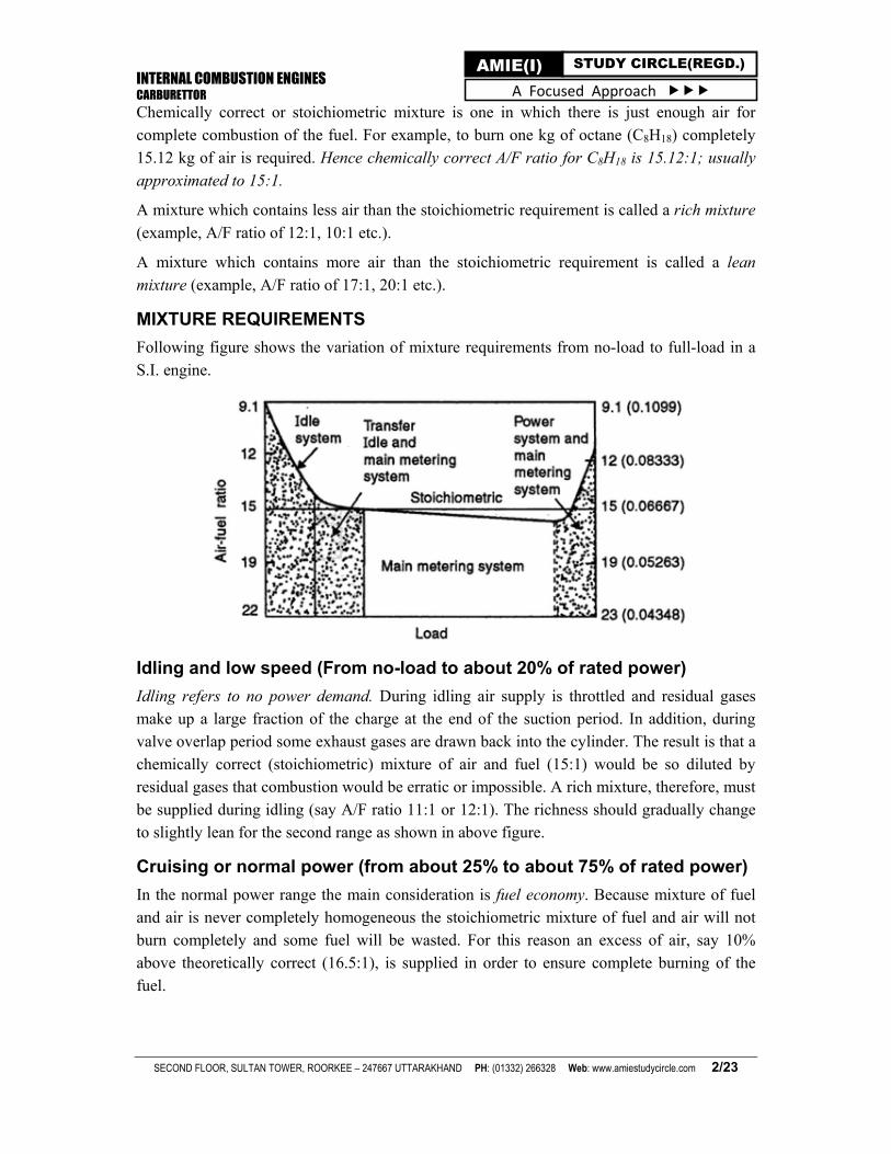
MIXTURE REQUIREMENTS
Following figure shows the variation of mixture requirements from no-load to full-load in a
S.I. engine.
Idling and low speed (From no-load to about 20% of rated power)
Idling refers to no power demand. During idling air supply is throttled and residual gases make up a large fraction of the charge at the end of the suction period. In addition, during valve overlap period some exhaust gases are drawn back into the cylinder. The result is that a chemically correct (stoichiometric) mixture of air and fuel (15:1) would be so diluted by residual gases that combustion would be erratic or impossible. A rich mixture, therefore, must be supplied during idling (say A/F ratio 11:1 or 12:1). The richness should gradually change to slightly lean for the second range as shown in above figure.
Cruising or normal power (from about 25% to about 75% of rated power)
In the normal power range the main consideration is fuel economy. Because mixture of fuel and air is never completely homogeneous the stoichiometric mixture of fuel and air will not burn completely and some fuel will be wasted. For this reason an excess of air, say 10% above theoretically correct (16.5:1), is supplied in order to ensure complete burning of the fuel.

INTERNAL COMBUSTION ENGINES CARBURETTOR
SECOND FLOOR, SULTAN TOWER, ROORKEE – 247667 UTTARAKHAND PH: (01332) 266328 Web: www.amiestudycircle.com 3/23
AMIE(I) STUDY CIRCLE(REGD.) A Focused Approach
Maximum power (From 75% to 100% of rated power)
Maximum power is obtained when all the air supplied is fully utilized. As the mixture is not completely homogeneous a rich mixture must be supplied to assure utilization of air (though this would mean wasting some fuel, which would pass in exhaust in unburned state). The air-fuel ratio for maximum power is about 13:1.
Running on the weakest mixture. This results in high efficiency and there is fuel economy.
On normal loads engines work on weak mixture.
PRINCIPLE OF CARBURETION
Until air and gasoline are drawn through the carburettor and into the engine cylinders by the suction created by the downward movement of the piston. This suction is due to an increase in the volume of the cylinder and a consequent decrease in the gas pressure in this chamber. It is the difference in pressure between the atmosphere and cylinder that causes the air to flow into the chamber. In the carburettor, air passing into the combustion chamber picks up fuel discharged from a tube. This tube has a fine orifice called carburettor jet which is exposed to the air path. The rate at which fuel is discharged into the air depends on the pressure difference or pressure head between the float chamber and the throat of the venturi and on the area of the outlet of the tube. In order that the fuel drawn from the nozzle may be thoroughly atomized, the suction effect must be strong and the nozzle outlet comparatively small. In order to produce a strong suction, the pipe in the carburettor carrying air to the engine is made to have a restriction. At this restriction called throat due to increase in velocity of flow, a suction effect is created. The restriction is made in the form of a venturi as
shown in following figure to minimize throttling losses.
The end of the fuel jet is located at the venturi or throat of the carburettor.
The geometry of venturi tube is as shown in figure. It has a narrower path at the centre so that the flow area through which the air must pass is considerably reduced. As the same amount of air must pass through every point in the tube, its velocity will be greatest at the narrowest point. The smaller the area, the greater will he the velocity of the air, and thereby the suction is proportionately increased.
INTERNAL COMBUSTION ENGINES CARBURETTOR
SECOND FLOOR, SULTAN TOWER, ROORKEE – 247667 UTTARAKHAND PH: (01332) 266328 Web: www.amiestudycircle.com 4/23
AMIE(I) STUDY CIRCLE(REGD.) A Focused Approach
As mentioned earlier, the opening of the fuel discharge jet is usually located where the suction is maximum. Normally, this is just below the narrowest section of the venturi tube. The spray of gasoline from the nozzle and the air entering through the venturi tube are mixed together in this region and a combustible mixture is formed which passes through the intake manifold into the cylinders. Most of the fuel gets atomized and simultaneously a small part
will be vapourized.
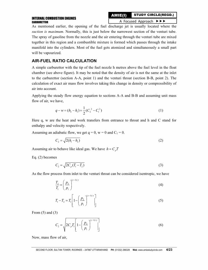
AIR-FUEL RATIO CALCULATION
A simple carburettor with the tip of the fuel nozzle h metres above the fuel level in the float chamber (see above figure). It may be noted that the density of air is not the same at the inlet to the carburettor (section A-A, point 1) and the venturi throat (section B-B, point 2). The calculation of exact air mass flow involves taking this change in density or compressibility of air into account.
Applying the steady flow energy equation to sections A-A and B-B and assuming unit mass
flow of air, we have,
2 22 1 2 1
1( ) ( )
2q w h h C C (1)
Here q, w are the heat and work transfers from entrance to throat and h and C stand for
enthalpy and velocity respectively.
Assuming an adiabatic flow, we get q = 0, w = 0 and C1 = 0.
2 1 22( )C h h (2)
Assuming air to behave like ideal gas. We have ph C T
Eq. (2) becomes
2 1 22 ( )pC C T T (3)
As the flow process from inlet to the venturi throat can be considered isentropic, we have
( 1)/
2 2
1 1
T p
T p
(4)
( 1)/
21 2 1
1
1p
T T Tp
(5)
From (5) and (3)
( 1)/
22 1
1
2 1p
pC C T
p
(6)
Now, mass flow of air,

INTERNAL COMBUSTION ENGINES CARBURETTOR
SECOND FLOOR, SULTAN TOWER, ROORKEE – 247667 UTTARAKHAND PH: (01332) 266328 Web: www.amiestudycircle.com 5/23
AMIE(I) STUDY CIRCLE(REGD.) A Focused Approach
1 1 1 2 2 2am AC A C (7)
where A1 and A2 are the cross sectional area at air inlet (point 1) and venturi throat (point 2).
To calculate the mass flow rate of air at venturi throat, we have
1 1 2 2/ /p p (8)
1/2 2 1 1( / )p p
1/ ( 1)/
2 21 2 1
1 1
2 1a p
p pm A C T
p p
(9)
= 1/ ( 1)/
2 1 22 1
1 1 1
2 1p
p p pA C T
p RT p
= 2/ ( 1)/
2 1 2 2
1 11
2 p
A p p pC
p pR T
(10)
Substituting Cp = 1005 J/kg K, = 1.4, R = 287 J/kg K for air.
1.43 1.71
2 1 2 2
1 11
0.1562.a
A p p pm
p pT
= 2 1
1
0.1562.A p
T kg/s (11)
where = 1.43 1.71
2 2
1 1
p p
p p
` (12)
Here, p is in N/m2, A is in m2 and T is in K.
Equation 11 gives the theoretical mass flow rate. To get the actual mass flow rate, the above
equation should be multiplied by the co-efficient of discharge for the venturi, Cda.
2 1,
1
0.1562a actual da
A pm C
T (13)
Since Cda and A2 are constants for a given venturi
1,
1
a actual
pm
T (14)
In order to calculate the air-fuel ratio, fuel flow rate is to be calculated. As the fuel is
incompressible, applying Bernoulli's Theorem we get
INTERNAL COMBUSTION ENGINES CARBURETTOR
SECOND FLOOR, SULTAN TOWER, ROORKEE – 247667 UTTARAKHAND PH: (01332) 266328 Web: www.amiestudycircle.com 6/23
AMIE(I) STUDY CIRCLE(REGD.) A Focused Approach
1 22ff
p pC gz
Mass flow rate of fuel
f f f fm A C (16)
= 1 22 ( )f f fA p p gz (17)
where Af is the area of cross section of the nozzle and f is the density of the fuel
, 1 22 ( )f actual df f f fm C A p p gz (18)
where Cdf is the coefficient of discharge for fuel nozzle.
A/F ratio = ma, actual/mf, actual
2 1
1 1 2
0.1562 . .2 ( )
da
df f f f
C A pA
F C A T p p gz
(19)
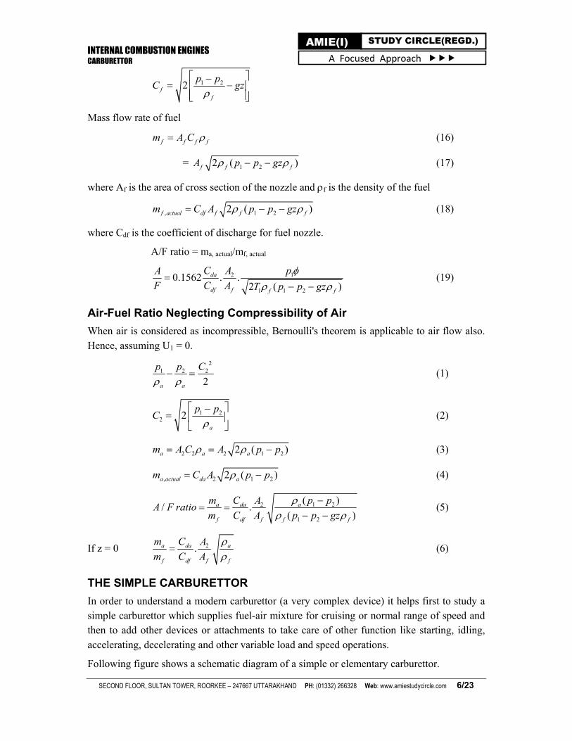
Air-Fuel Ratio Neglecting Compressibility of Air
When air is considered as incompressible, Bernoulli's theorem is applicable to air flow also. Hence, assuming U1 = 0.
2
1 2 2
2a a
p p C
(1)
1 22 2
a
p pC
(2)
2 2 2 1 22 ( )a a am A C A p p (3)
, 2 1 22 ( )a actual da am C A p p (4)
1 22
1 2
( )/ .
( )a da a
f df f f f
m C p pAA F ratio
m C A p p gz
(5)
If z = 0 2.a da a
f df f f
m C A
m C A
(6)
THE SIMPLE CARBURETTOR
In order to understand a modern carburettor (a very complex device) it helps first to study a simple carburettor which supplies fuel-air mixture for cruising or normal range of speed and then to add other devices or attachments to take care of other function like starting, idling,
accelerating, decelerating and other variable load and speed operations.
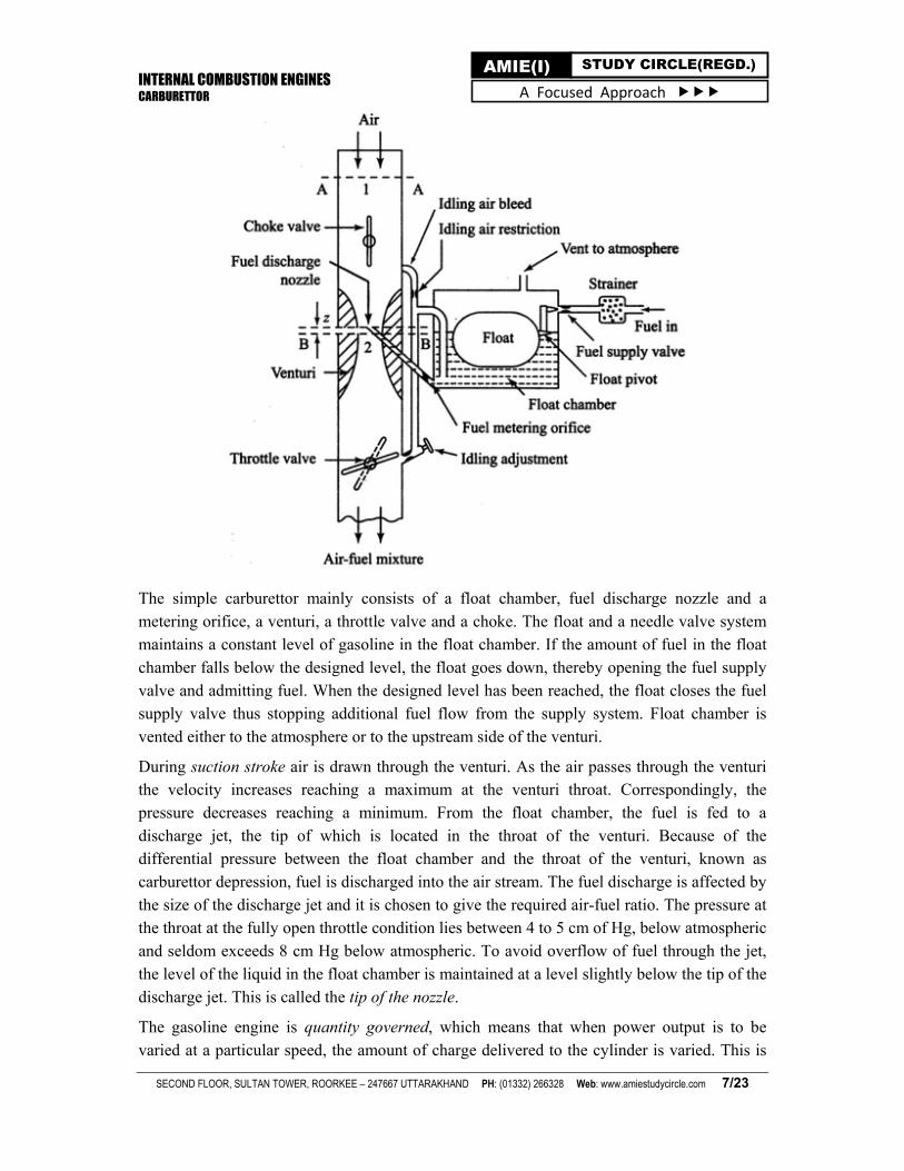
Following figure shows a schematic diagram of a simple or elementary carburettor.
INTERNAL COMBUSTION ENGINES CARBURETTOR
SECOND FLOOR, SULTAN TOWER, ROORKEE – 247667 UTTARAKHAND PH: (01332) 266328 Web: www.amiestudycircle.com 7/23
AMIE(I) STUDY CIRCLE(REGD.) A Focused Approach
The simple carburettor mainly consists of a float chamber, fuel discharge nozzle and a metering orifice, a venturi, a throttle valve and a choke. The float and a needle valve system maintains a constant level of gasoline in the float chamber. If the amount of fuel in the float chamber falls below the designed level, the float goes down, thereby opening the fuel supply valve and admitting fuel. When the designed level has been reached, the float closes the fuel supply valve thus stopping additional fuel flow from the supply system. Float chamber is
vented either to the atmosphere or to the upstream side of the venturi.
During suction stroke air is drawn through the venturi. As the air passes through the venturi the velocity increases reaching a maximum at the venturi throat. Correspondingly, the pressure decreases reaching a minimum. From the float chamber, the fuel is fed to a discharge jet, the tip of which is located in the throat of the venturi. Because of the differential pressure between the float chamber and the throat of the venturi, known as carburettor depression, fuel is discharged into the air stream. The fuel discharge is affected by the size of the discharge jet and it is chosen to give the required air-fuel ratio. The pressure at the throat at the fully open throttle condition lies between 4 to 5 cm of Hg, below atmospheric and seldom exceeds 8 cm Hg below atmospheric. To avoid overflow of fuel through the jet, the level of the liquid in the float chamber is maintained at a level slightly below the tip of the discharge jet. This is called the tip of the nozzle.
The gasoline engine is quantity governed, which means that when power output is to be varied at a particular speed, the amount of charge delivered to the cylinder is varied. This is
INTERNAL COMBUSTION ENGINES CARBURETTOR
SECOND FLOOR, SULTAN TOWER, ROORKEE – 247667 UTTARAKHAND PH: (01332) 266328 Web: www.amiestudycircle.com 8/23
AMIE(I) STUDY CIRCLE(REGD.) A Focused Approach
achieved by means of a throttle valve usually of the butterfly type which is situated after the venturi tube. As the throttle is closed less air flows through the venturi tube and less is the quantity of air-fuel mixture delivered to the cylinder and hence power output is reduced. As the throttle is opened, more air flows through the choke tube resulting in increased quantity of mixture being delivered to the engine. This increases the engine power output.
A simple carburettor of the type described above suffers from a fundamental drawback in that it provides the required A/F ratio only at one throttle position. At the other throttle positions the mixture is either leaner or richer depending on whether the throttle is opened less or more. As the throttle opening is varied, the air flow varies and creates a certain pressure differential between the float chamber and the venturi throat. The same pressure differential regulates the flow of fuel through the nozzle. Therefore, the velocity of flow of air and fuel vary in a similar manner. At the same time, the density of air decreases as the pressure at the venturi throat decreases with increasing air flow whereas that of the fuel remains unchanged. This results in a simple carburettor producing a progressively rich mixture with increasing throttle
opening.
COMPLETE CARBURETTOR
For meeting the demand of the engine under all conditions of operation, the following
additional devices/systems are added to the simple carburettor :
Main metering system
Idling system
Power enrichment or economiser system
Acceleration pump system
Choke.
Main Metering System
The main metering system of a carburettor should be so designed as to supply a nearly constant fuel-air ratio over a wide range of operation. This F/A ratio is approximately equal to 0.064 (A/ F ratio = 15.6) for best economy at full throttle In order to correct the tendency of the simple carburettor to give progressively richer mixtures with load speed, the following
automatic compensating devices are incorporated in the main metering system:
Compensating jet device.
Emulsion tube or air bleeding device,
Back suction control or pressure reduction method.
Auxiliary valve carburettor.
Auxiliary port carburettor.

INTERNAL COMBUSTION ENGINES CARBURETTOR
SECOND FLOOR, SULTAN TOWER, ROORKEE – 247667 UTTARAKHAND PH: (01332) 266328 Web: www.amiestudycircle.com 9/23
AMIE(I) STUDY CIRCLE(REGD.) A Focused Approach
Emulsion tube or air bleeding device
The mixture correction in modern carburettor is done by air bleeding alone. Such an
arrangement is shown in following figure.
A main metering jet is fitted 25 mm below the petrol level in the float chamber and therefore it is called submerged jet. The jet is situated at the bottom of a well, the sides of which have holes which are in communication with the atmosphere. Air is drawn through the holes and the petrol is emulsified; the pressure difference across the petrol column is not as great as that
in the simple carburettor.
Initially the level of petrol in the float chamber and the well is same. When throttle is opened the pressure at the venturi decreases and the petrol is drawn into the air stream. This results in progressively uncovering the holes in the central tube leading to decreasing F/A ratio or
decreasing richness of the mixture. Normal flow then takes place from the main jet.
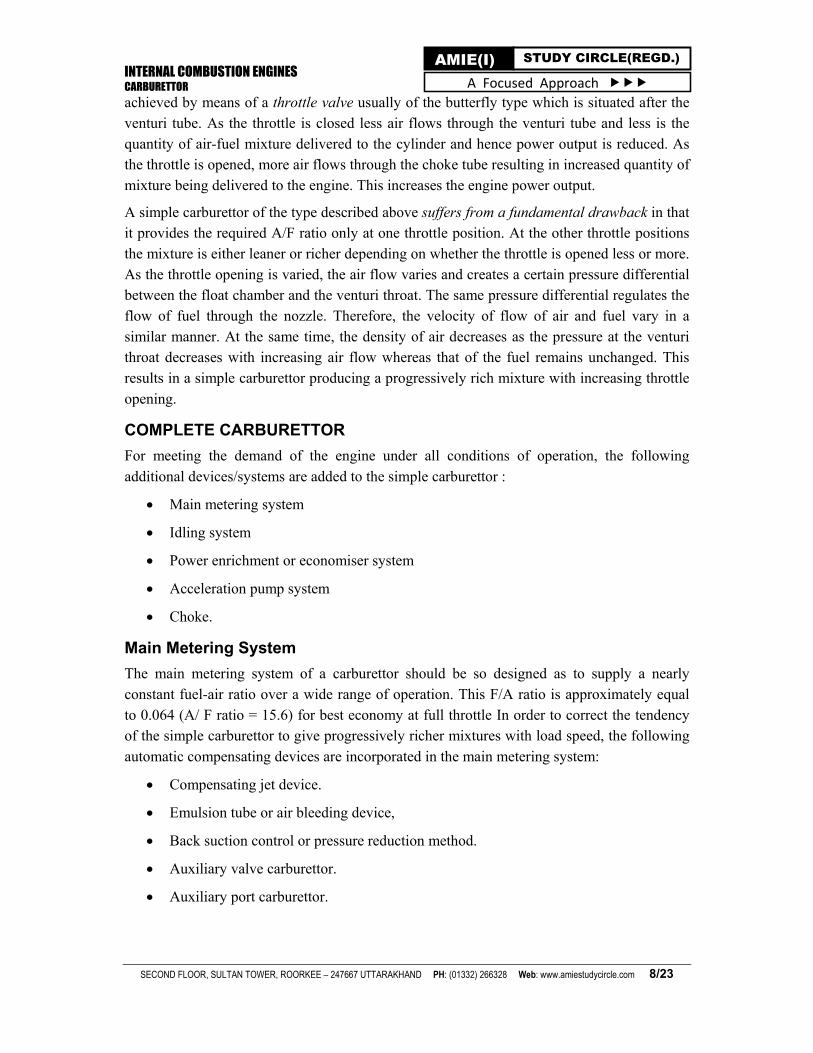
Idling System
At idling and low load an engine requires a rich mixture having about air-fuel ratio 12 :1. The main metering system not only fails to supply enrich the mixture at low air flows but also cannot supply any fuel during idling operation. It is due to this reason that a separate idling
jet must be incorporated in the basic carburettor.
Given figure shows an idling jet. It consists of a small fuel line from the float chamber to a point on the engine side of the throttle ; this line contains a fixed fuel orifice.
When throttle is practically closed, the full manifold suction operates on the outlet to this jet. Besides local suction is increased due to very high velocity past the throttle valve. Fuel therefore can be lifted by the additional height upto the discharge point, but this occurs only
at very low rates of air flow.
INTERNAL COMBUSTION ENGINES CARBURETTOR
SECOND FLOOR, SULTAN TOWER, ROORKEE – 247667 UTTARAKHAND PH: (01332) 266328 Web: www.amiestudycircle.com 10/23
AMIE(I) STUDY CIRCLE(REGD.) A Focused Approach
When the throttle is opened, the main jet gradually takes over and the idle jet eventually
becomes ineffective.
The idle adjust (a needle valve controlling the air bleed, which is manually operated) regulates the desired A IF ratio for the idling jet.
Power Enrichment or Economiser System
At the maximum power range of operation from 75% to 100% load, a device should be available to allow richer mixture (F/A about 0.08) to be supplied despite the compensating leanness. Meter rod economiser shown in following figure is such a device. It simply provides a large orifice opening to the main jet when the throttle is opened beyond specified limit. The rod may be tapered or stepped.
An economiser is a valve which remains closed at normal cruise operation and gets opened to supply enriched mixture at full throttle operation. It regulates the additional fuel supply for the above operation.
The term economiser is rather misleading. It stems from the fact that such a device provides a rich uneconomical mixture at high load demand without interfering with economical operation in the normal power range.
INTERNAL COMBUSTION ENGINES CARBURETTOR
SECOND FLOOR, SULTAN TOWER, ROORKEE – 247667 UTTARAKHAND PH: (01332) 266328 Web: www.amiestudycircle.com 11/23
AMIE(I) STUDY CIRCLE(REGD.) A Focused Approach
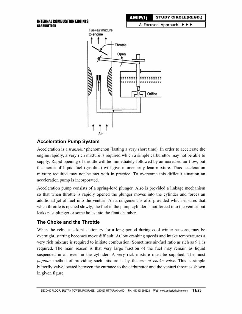
Acceleration Pump System
Acceleration is a transient phenomenon (lasting a very short time). In order to accelerate the engine rapidly, a very rich mixture is required which a simple carburettor may not be able to supply. Rapid opening of throttle will be immediately followed by an increased air flow, but the inertia of liquid fuel (gasoline) will give momentarily lean mixture. Thus acceleration mixture required may not be met with in practice. To overcome this difficult situation an acceleration pump is incorporated.
Acceleration pump consists of a spring-load plunger. Also is provided a linkage mechanism so that when throttle is rapidly opened the plunger moves into the cylinder and forces an additional jet of fuel into the venturi. An arrangement is also provided which ensures that when throttle is opened slowly, the fuel in the pump cylinder is not forced into the venturi but leaks past plunger or some holes into the float chamber.
The Choke and the Throttle
When the vehicle is kept stationary for a long period during cool winter seasons, may be overnight, starting becomes move difficult. At low cranking speeds and intake temperatures a very rich mixture is required to initiate combustion. Sometimes air-fuel ratio as rich as 9:1 is required. The main reason is that very large fraction of the fuel may remain as liquid suspended in air even in the cylinder. A very rick mixture must be supplied. The most popular method of providing such mixture is by the use of choke valve. This is simple butterfly valve located between the entrance to the carburettor and the venturi throat as shown in given figure.

INTERNAL COMBUSTION ENGINES CARBURETTOR
SECOND FLOOR, SULTAN TOWER, ROORKEE – 247667 UTTARAKHAND PH: (01332) 266328 Web: www.amiestudycircle.com 12/23
AMIE(I) STUDY CIRCLE(REGD.) A Focused Approach
When the choke is partly closed, large pressure drop occurs at the venturi throat that would normally result from the quantity of air passing through the venturi throat. The very large depression at the throat inducts large amount of fuel from the main nozzle and provides a very rich mixture so that the ratio of the evaporated fuel to air in the cylinder is within the combustible limits. Sometimes, the choke valves are spring loaded to ensure that large carburettor depression and excessive choking docs not persist after the engine has started, and reached a desired speed. This choke can be made to operate automatically by means of a thermostat so that the choke is closed when engine is cold and goes out of operation when engine warms up alter starting. The speed and the output of an engine is controlled by the use of the throttle valve, which is located on the downstream side of the venturi. The more the throttle is closed the greater is the obstruction to the How of the mixture placed in the passage and the less is the quantity of mixture delivered to the cylinders. The decreased quantity of mixture gives a less powerful impulse to the pistons and the output of the engine is reduced accordingly. As the throttle is opened, the output of the engine increases. Opening the throttle usually increases the speed of the engine. In short, the throttle is simply a means to regulate
the output of the engine by varying the quantity of charge going into the cylinder.
MULTIJET CARBURETTORS
A single barrel carburettor has only one barrel, whereas a dual carburettor lias two barrels. Each of these two barrels in a dual carburettor contains a fuel jet, a venturi tube, an idling system, a choke and a throttle. The float chamber and the accelerating pump are common to
both the barrels.
INTERNAL COMBUSTION ENGINES CARBURETTOR
SECOND FLOOR, SULTAN TOWER, ROORKEE – 247667 UTTARAKHAND PH: (01332) 266328 Web: www.amiestudycircle.com 13/23
AMIE(I) STUDY CIRCLE(REGD.) A Focused Approach
Passenger cars with six or more cylinders, are provided with dual carburettors. Each venturi
supplies the air-fuel mixture to half the cylinders.
Certain advantages of a dual carburettor over a single barrel carburettor are:
The dual carburettor supplies a charge of the mixture to the cylinders which is uniform in quality.
Volumetric efficiency is higher in case of a dual carburettor.
The charge of the air-fuel mixture is distributed to each cylinder in a better manner.
The dual carburettor Ls compact in its design.
PETROL INJECTION
Drawbacks of Modern Carburettors
The modern carburettors have the following drawbacks:
The mixture supplied to various cylinders of a multi-cylinder engine varies in quality and quantity. Also, due to fuel condensation in induction manifold, the mixture
proportion is affected.
Due to presence of several wearing parts, the carburettors operate at a lower efficiency.
Reduced volumetric efficiency due to non availability of a free flow passage for the
mixture owing to the presence of choke tubes, throttle valves, jets, bends etc.
At low temperatures, freezing can occur (if special means to obviate this are not provided).
When the carburettor is tilted or during acrobatics in aircraft surging can occur (if means to avoid this are not provided).
In the absence of flame traps, backfiring may occur which may lead to ignition of fuel outside the carburettor.
Introduction to Fuel Injection
The function of a fuel injection system is :
To monitor the engine's operating variables,
To transfer this information to a metering control, then
To discharge and atomise the fuel into the incoming air stream.
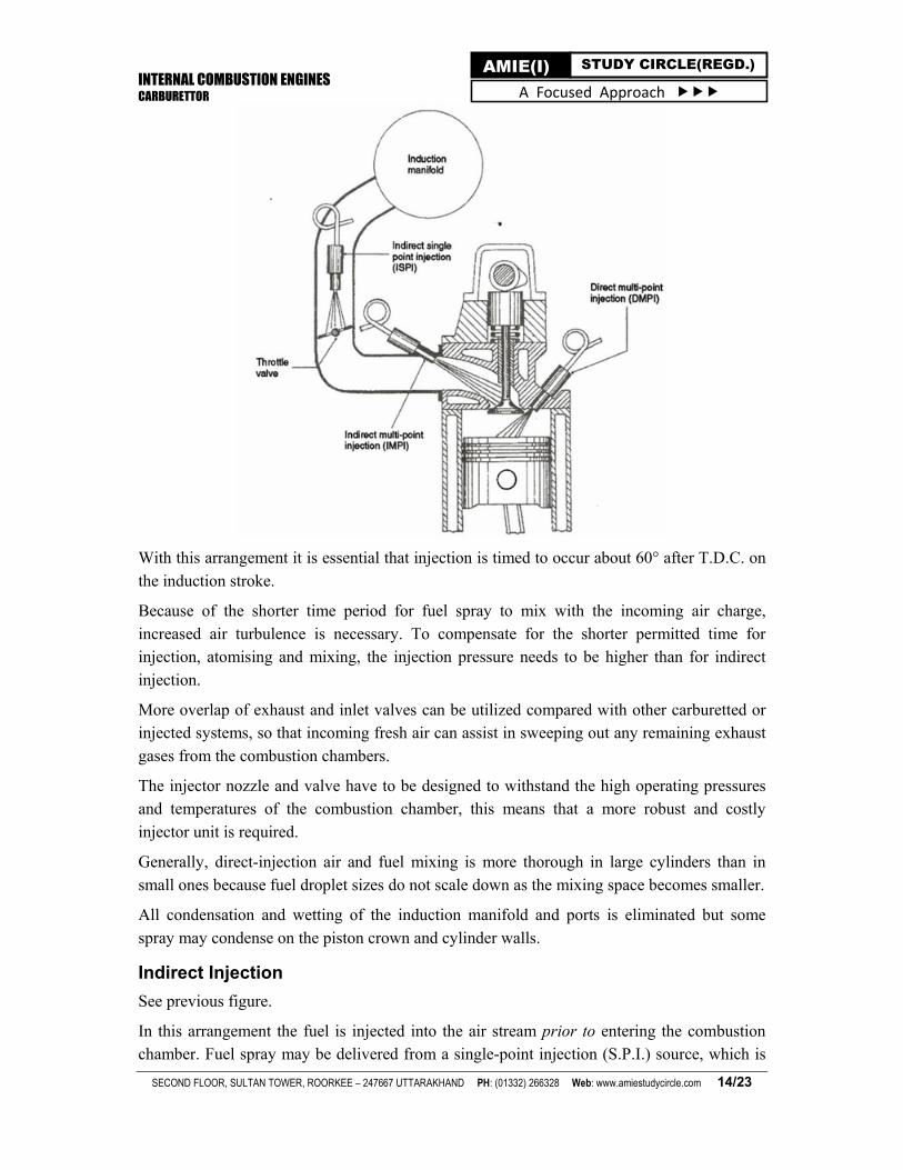
Direct Injection
See given figure.
In this type of layout the fuel injectors are positioned in the cylinder-head so that fuel is
directly discharged into each combustion chamber.
INTERNAL COMBUSTION ENGINES CARBURETTOR
SECOND FLOOR, SULTAN TOWER, ROORKEE – 247667 UTTARAKHAND PH: (01332) 266328 Web: www.amiestudycircle.com 14/23
AMIE(I) STUDY CIRCLE(REGD.) A Focused Approach
With this arrangement it is essential that injection is timed to occur about 60° after T.D.C. on
the induction stroke.
Because of the shorter time period for fuel spray to mix with the incoming air charge, increased air turbulence is necessary. To compensate for the shorter permitted time for injection, atomising and mixing, the injection pressure needs to be higher than for indirect
injection.
More overlap of exhaust and inlet valves can be utilized compared with other carburetted or injected systems, so that incoming fresh air can assist in sweeping out any remaining exhaust
gases from the combustion chambers.
The injector nozzle and valve have to be designed to withstand the high operating pressures and temperatures of the combustion chamber, this means that a more robust and costly
injector unit is required.
Generally, direct-injection air and fuel mixing is more thorough in large cylinders than in small ones because fuel droplet sizes do not scale down as the mixing space becomes smaller.
All condensation and wetting of the induction manifold and ports is eliminated but some
spray may condense on the piston crown and cylinder walls.
Indirect Injection
See previous figure.
In this arrangement the fuel is injected into the air stream prior to entering the combustion chamber. Fuel spray may be delivered from a single-point injection (S.P.I.) source, which is

INTERNAL COMBUSTION ENGINES CARBURETTOR
SECOND FLOOR, SULTAN TOWER, ROORKEE – 247667 UTTARAKHAND PH: (01332) 266328 Web: www.amiestudycircle.com 15/23
AMIE(I) STUDY CIRCLE(REGD.) A Focused Approach
usually just upstream from the throttle (air intake side of the throttle), or it may be supplied from a multi-point injection (M.P.I.) source, where the injectors are positioned in each
induction manifold branch pipe just in front of the inlet port.
Indirect injection can be discharged at relatively low pressure (2 to 6 bar) and need not be synchronized to the engine's induction cycle. Fuel can be discharged simultaneously to each
induction pipe where it is mixed and stored until the inlet valve opens.
Since indirect injection does not need to be timed, it requires only low discharge pressures and the injectors are not exposed to combustion, the complexity of the operating mechanisms can be greatly reduced, which considerably lowers cost The single-point injection system has the same air and fuel mixing and distribution problems as a carburettor layout but without venturi restriction so that higher engine volumetric efficiencies are obtained. High injection pressures, compared with the carburettor discharge method of fuel delivery, speed up and improve the atomization of the liquid spray.
The multi-point injection layout, in contrast to the single-point injection method has no fuel distribution difficulties since each injector discharges directly into its own induction port and the mixture then has only to move a short distance before it enters the cylinder. Since the induction manifold deals mainly with only induced air, the branch pipes can be enlarged and
extended to maximize the ram effect of the incoming air charge.
A major feature with petrol injection is that there is separate air and fuel metering and that fuel metering is precise under all engine operating condition's.
Injection Considerations
The fuel can be discharged into the air stream, using indirect injection arrangements, by the
following two methods:
Continuous injection. In this arrangement, the injector nozzle and valve are permanently open while the engine is operating and the amount of fuel discharged in the form of a spray is controlled by either varying the metering orifice or the fuel discharge pressure, or a
combination of both of these possible variables.
Intermittent or pulsed injection. In this type of injection, fuel is delivered from the injector in spray form at regular intervals with a constant fuel discharge pressure and the amount of
fuel discharged is controlled by the time period the injector nozzle valve is open.
Timed injection. This where the start of delivery for each cylinder occurs at the same angular point in the engine cycle, this can be anything from 600 to 900 after T.D.C. on the induction stroke.
Non-timed injection. In contrast to timed injection, this is where all the injectors are programmed to discharge their spray at the same time, therefore each cylinder piston will be on a different part of the engine cycle.
Merits of Petrol Injection
Following are the merits of petrol engine system:

INTERNAL COMBUSTION ENGINES CARBURETTOR
SECOND FLOOR, SULTAN TOWER, ROORKEE – 247667 UTTARAKHAND PH: (01332) 266328 Web: www.amiestudycircle.com 16/23
AMIE(I) STUDY CIRCLE(REGD.) A Focused Approach
In petrol injection system, due to absence of venturi there is the minimum of air restriction so that higher engine volumetric efficiencies can be obtained with the
corresponding improvement in power and torque.
The spots for pre-heating the cold air and fuel mixture are eliminated so that denser air enters the cylinder when the engine has reached normal operating conditions.
As the manifold branch pipes are not greatly concerned with mixture preparation they can be designed to utilize the inertia of the air charge to increase the engine's
volumetric efficiency; (this does not apply for single point injection).
Because of direct spray discharge into each inlet port, acceleration response is better.
Atomization of fuel droplets is generally improved over normal speed and load driving conditions.
It is possible to use greater inlet and exhaust valve overlap without poor idling, loss of fuel or increased exhaust pollution.
The monitoring of engine operating parameters enables accurate matching of air and fuel requirements under normal speed and load conditions which improves engine
performance, fuel consumption and reduces exhaust pollution.
Fuel injection equipment is precise in metering injected fuel spray into the intake ports over the complete engine speed, load and temperature operating range.
There is precise fuel distribution between engine cylinders even under full load conditions with multi-point injection,
Multi-point injection does not require time for fuel transportation in the intake manifold and there is no manifold wall melting.
With fuel injection, when cornering fast or due to heavy braking, fuel surge is eliminated.
Demerits/Limitations of Petrol Injection
Petrol injection system entails the following demerits/limitations:
Initial cost of equipment is high ; replacement parts are also expensive.
Increased care and attention required.
In order to diagnose fuel injection system faults and failures, special servicing
equipment is necessary.
It is necessary to have considerably more mechanical and electrical knowledge to diagnose and rectify the faults of fuel equipment.
Injection equipment may be elaborately complicated, delicate to handle and
impossible to service.
More electrical and mechanical components to go wrong.
INTERNAL COMBUSTION ENGINES CARBURETTOR
SECOND FLOOR, SULTAN TOWER, ROORKEE – 247667 UTTARAKHAND PH: (01332) 266328 Web: www.amiestudycircle.com 17/23
AMIE(I) STUDY CIRCLE(REGD.) A Focused Approach
Due to pumping and metering of the fuel there is increased mechanical and hydraulic noise.
Due to the fine working tolerances of the metering and discharging components, very
careful filtration is needed.
To drive the fuel pressure pump or injection discharge devices, power (be it electrical or mechanical) is necessary.
More bulky and heavy (than that of a carburetted fuel supply system).
ELECTRONIC FUEL INJECTION SYSTEM
Modern gasoline injection systems use engine sensors, a computer, and solenoid operated fuel injectors to meter and inject the right amount of fuel into the engine cylinders. These systems called electronic fuel injection (EFI) use electrical and electronic devices to monitor and control engine-operation.
An electronic control unit (ECU) or the computer receives electrical signals in the form of current or voltage from various sensors. It then uses the stored data to operate the injectors, ignition system and other engine related devices. As a result, less unburned fuel leaves the
engine as emissions, and the vehicle gives better mileage.
The fuel injector in an EFI is nothing but a fuel valve. When il is not energized, spring pressure makes the injector to remain closed and no fuel will enter the engine. When the computer sends the signal through the injector coil, the magnetic field attracts the injector
armature. Fuel then spurts into the intake manifold.
The injector pulse width is an indication of the period for which each injector is energized and kept open. The computer decides and controls the injector pulse width based on the
signals received from the various sensors.
Under full load, the computer will sense a wide open throttle, high intake manifold pressure, and high inlet air How. The ECU will then increase the injector pulse width to enrich the
mixture which will enable the engine to produce higher power.
Under low load and idling conditions, the ECU will shorten the pulse width by which the injectors are kept in the closed position over a longer period of time. Because of this, air-fuel
mixture will become leaner and will result in better fuel economy.
Electronic fuel injection system has a cold start injector too. This is an extra injector that sprays fuel into the centre of the engine intake manifold, when the engine is cold. It serves the same purpose as the carburettor choke. The cold start injector ensures easy engine startup
in very cold weather.
MULTI-POINT FUEL INJECTION (MPFI) SYSTEM
The main purpose of the Multi-Point Fuel Injection (MPFI) system is to supply a proper ratio of gasoline and air to the cylinders. These systems function under two basic arrangements, namely

INTERNAL COMBUSTION ENGINES CARBURETTOR
SECOND FLOOR, SULTAN TOWER, ROORKEE – 247667 UTTARAKHAND PH: (01332) 266328 Web: www.amiestudycircle.com 18/23
AMIE(I) STUDY CIRCLE(REGD.) A Focused Approach
Port injection
Throttle body injection
Port Injection
In the port injection arrangement, the injector is placed on the side of the intake manifold
near the intake port (see figure).
The injector sprays gasoline into the air, inside the intake manifold. The gasoline mixes with the air in a reasonably uniform manner. This mixture of gasoline and air then passes through
the intake valve and enters into the cylinder.
Every cylinder is provided with an injector in its intake manifold. If there are six cylinders, there will be six injectors. Following figure shows a simplified view of a port or multi point
fuel injection (MPFI) system.
ALTITUDE COMPENSATION DEVICES
The problem of mixture enrichment is quite acute in aircraft carburettors. At higher altitudes, density of air is less and therefore the mass of the air taken into engine decreases and the power is reduced in approximately the same proportion. Since, the quantity of oxygen taken into the engine decreases, the fuel-air mixture becomes too rich for normal operation. The mixture strength delivered by the carburettor becomes richer at a rate inversely
proportional to the square root of the density ratio.
INTERNAL COMBUSTION ENGINES CARBURETTOR
SECOND FLOOR, SULTAN TOWER, ROORKEE – 247667 UTTARAKHAND PH: (01332) 266328 Web: www.amiestudycircle.com 19/23
AMIE(I) STUDY CIRCLE(REGD.) A Focused Approach
If the pressure remains constant, the density of the air will vary according to temperature, increasing as the temperature drops. This will cause a leaning of the fuel-air mixture in the carburettor because the denser air contains more oxygen. The change in air pressure due to altitude is considerably more of a problem than the change in density due to temperature changes. At 6,000 m altitude, the air pressure is approximately one-half the pressure at sea level. Hence, in order to provide a correct mixture, the fuel flow would have to be reduced to almost one-half what it would be at sea level. The adjustment of fuel flow to compensate for
changes in air pressure and temperature is a principal function of the mixture control.
Briefly, the mixture-control system can be described us a mechanism or device by means of which the richness of the mixture entering the engine during flight can be controlled to a reasonable extent. This control should exist through all normal altitudes of operation to prevent the mixture from becoming too rich at high altitudes and to economize on fuel during engine operation in the low-power range where cylinder temperature will not become
excessive with the use of the leaner mixture.
Mixture-control systems may be classified according to their principles of operation as:
back suction type, which reduces the effective suction on the metering system
needle type, which restricts the flow of fuel through the metering system; and
the air-port type, which allows additional air to enter the carburettor between the main discharge nozzle and the throttle valve.
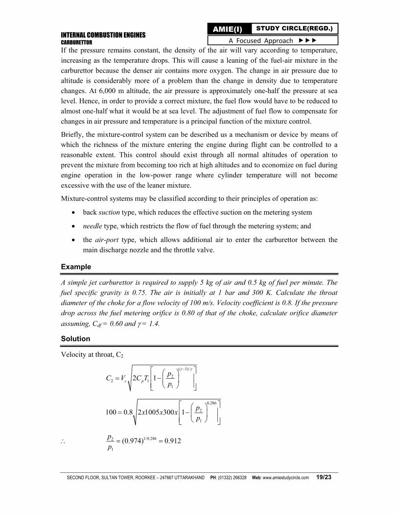
Example
A simple jet carburettor is required to supply 5 kg of air and 0.5 kg of fuel per minute. The fuel specific gravity is 0.75. The air is initially at 1 bar and 300 K. Calculate the throat diameter of the choke for a flow velocity of 100 m/s. Velocity coefficient is 0.8. If the pressure drop across the fuel metering orifice is 0.80 of that of the choke, calculate orifice diameter
assuming, Cdf = 0.60 and = 1.4.
Solution
Velocity at throat, C2
( 1)/
22 1
1
2 1c p
pC V C T
p
0.286
2
1
100 0.8 2 1005 300 1p
x x xp
1/0.2862
1
(0.974) 0.912p
p

INTERNAL COMBUSTION ENGINES CARBURETTOR
SECOND FLOOR, SULTAN TOWER, ROORKEE – 247667 UTTARAKHAND PH: (01332) 266328 Web: www.amiestudycircle.com 20/23
AMIE(I) STUDY CIRCLE(REGD.) A Focused Approach
311 5
1
0.287 3001000 0.861
10
RT xv x m
p
1 1 2 2p v p v
1/ 0.714
312 1
2
10.861 0.919 /
0.912
pv v x m kg
p
Throat area 4 222
2
5 0.91910 7.658
60 100am xv
A x x cmC
2
47.658 3.12d x cm
1 0.912 0.088ap
0.80 0.088 0.07fp x bar
2f f f f fm A C p
50.50.6 2 750 0.07 10
60 fA x x x x x
Af = 0.0428 cm2
and df = 2.34 mm
Problem
A simple jet carburettor has to supply 5 kg of air per minute. The air is at a pressure of 1.013 bar and at a temperature of 270C. Calculate the throat diameter of the choke for air flow velocity of 90 m/s. Take velocity coefficient to be 0.8. Assume isentropic flow. Assume flow to be compressible.
Answer: 3.25 cm
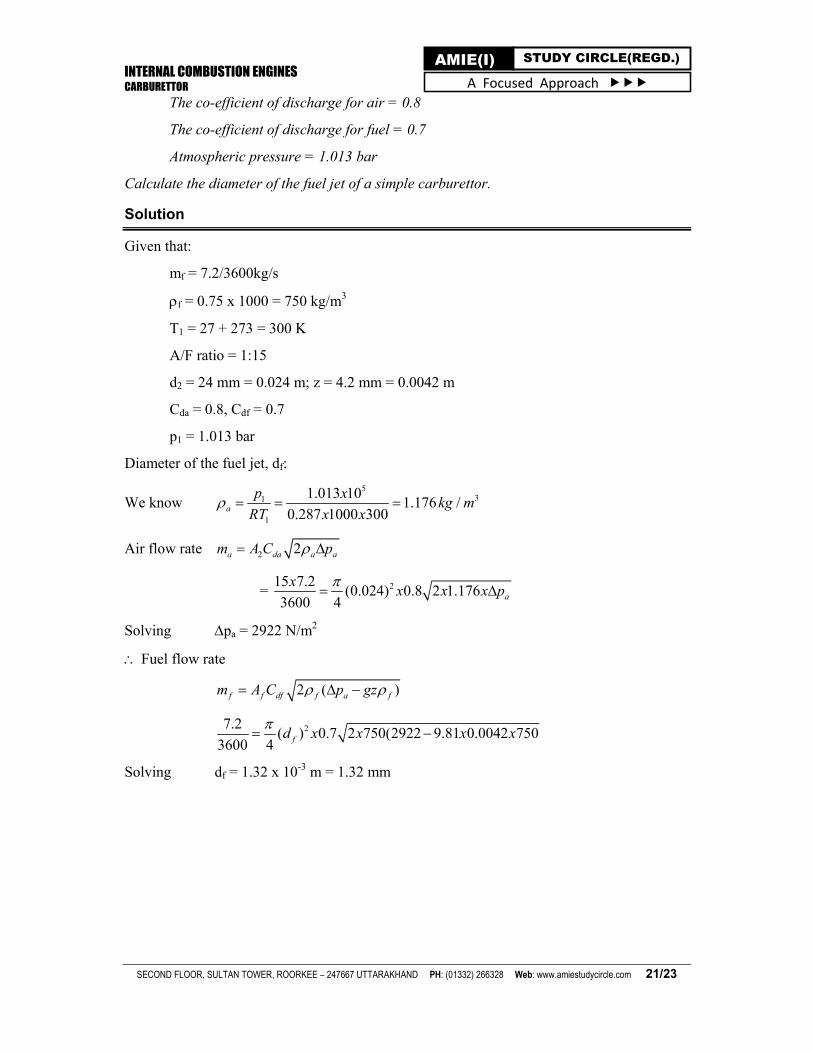
Example
The following data relate to a petrol engine:
Petrol consumed per hour = 7.2 kg
The specific gravity of the fuel = 0.75
The temperature of air = 27°C
The air fuel ratio = 1:15
The diameter of the choke tube = 24 mm
The height of top of the jet above the petrol level = 4.2 mm = 0.0042 m in the float
chamber
INTERNAL COMBUSTION ENGINES CARBURETTOR
SECOND FLOOR, SULTAN TOWER, ROORKEE – 247667 UTTARAKHAND PH: (01332) 266328 Web: www.amiestudycircle.com 21/23
AMIE(I) STUDY CIRCLE(REGD.) A Focused Approach
The co-efficient of discharge for air = 0.8
The co-efficient of discharge for fuel = 0.7
Atmospheric pressure = 1.013 bar
Calculate the diameter of the fuel jet of a simple carburettor.
Solution
Given that:
mf = 7.2/3600kg/s
f = 0.75 x 1000 = 750 kg/m3
T1 = 27 + 273 = 300 K
A/F ratio = 1:15
d2 = 24 mm = 0.024 m; z = 4.2 mm = 0.0042 m
Cda = 0.8, Cdf = 0.7
p1 = 1.013 bar
Diameter of the fuel jet, df:
We know 5
31
1
1.013 101.176 /
0.287 1000 300a
p xkg m
RT x x
Air flow rate 2 2a da a am A C p
= 215 7.2(0.024) 0.8 2 1.176
3600 4 a
xx x x p
Solving pa = 2922 N/m2
Fuel flow rate
2 ( )f f df f a fm A C p gz
27.2( ) 0.7 2 750(2922 9.81 0.0042 750
3600 4 fd x x x x
Solving df = 1.32 x 10⁻³ m = 1.32 mm

INTERNAL COMBUSTION ENGINES CARBURETTOR
SECOND FLOOR, SULTAN TOWER, ROORKEE – 247667 UTTARAKHAND PH: (01332) 266328 Web: www.amiestudycircle.com 22/23
AMIE(I) STUDY CIRCLE(REGD.) A Focused Approach
ASSIGNMENT Q.1. (AMIE S10, 6 marks): Write short notes on (i) stoichiometric fuel air ratio and (ii) lean and rich mixture operation.
Q.2. (AMIE W16, 8 marks): Why do we require a rich mixture during idling and sudden acceleration, while
lean mixture during cruising of SI Engine?
Q.3. (AMIE S16, 5 marks): Describe the effect of air-fuel ratio in SI engine.
Q.4. (AMIE S14, 10 marks): Discuss fresh mixture air-fuel ratio requirement in SI engine for various operating conditions.
Q.5. (AMIE S10, 12, 14, W11, 13, 14, 7 marks): Explain the working of single jet carburettor with a neat sketch.
Q.6. (AMIE W16, 9 marks): Briefly explain double venturi carburettor.
Q.7. (AMIE S15, 9 marks): Briefly explain following system for carburettor (i) idling system (ii) main metering system (iii) choke system.
Q.8. (AMIE W15, 6 marks): Draw and discuss the operation and function of emulsion tube in the carburettor.
Q.9. (AMIE S13, W13, 5 marks): State the essential requirements of a good carburettor for automotive
engines.
Q.10. (AMIE S15, 6 marks): If you have to design a carburettor for an aircraft, what special requirements you will have to consider? What is meant by attitude compensation?
Q.11. (AMIE W10, 8 marks): What is the requirement of a main metering system in a carburettor. Draw and discuss any one type of main metering system.
Q.12. (AMIE S12, 6 marks): Explain injector system in SI engine.
Q.13. (AMIE W12, 15, 7 marks): Explain the working of multipoint fuel injection in SI engines.
Q.14. (AMIE S15, 4 marks): Why is gasoline injection required?
Q.15. (AMIE S10, 3 marks): Write advantages of petrol injection system.
Q.16. (AMIE W16, 6 marks): What are advantages and disadvantages of MPFI system compared to conventional carburettor system?
Q.17. (AMIE W12, 4 marks): Draw and discuss idling system for a carburettor using additional suitable diagrams.
Q.18. (AMIE S07, 16, W10, 12, 15, 14 marks): Derive an expression for air to fuel ratio (i) neglecting compressibility of air (ii) taking compressibility into account. Use the expression and explain the limitations of a simple carburettor.
Q.19. (AMIE W11, 10 marks): Obtain the following expression of actual fuel-air ratio of a carburettor:
1 1 2
1.43 1.712 1 2 1 2 1
2 ( )1/ . . .
4.94 ( / ) ( / )
f fdf f
da
T p p gzC AF A
C A p p p p p
Q.20. (AMIE S10, 10 marks): A simple carburettor is designed to supply 6 kg of air and 0.45 kg of fuel per minute to the four stroke single cylinder petrol engine. The ambient air is at 1.013 bar and 300 K. (i) calculate
the throat diameter of the choke (venturi) when the velocity of air is limited to 92 m/s. Take f = 740 kg/m3 and
velocity coeff. = 0.8. (ii) if the pressure drop near the fuel nozzle is 75% of that at the venturi; calculate the fuel nozzle diameter. Take Cdf = 0.6.
Answer: (i) 3.525 cm (ii) 2.343 mm

INTERNAL COMBUSTION ENGINES CARBURETTOR
SECOND FLOOR, SULTAN TOWER, ROORKEE – 247667 UTTARAKHAND PH: (01332) 266328 Web: www.amiestudycircle.com 23/23
AMIE(I) STUDY CIRCLE(REGD.) A Focused Approach
Q.21. (AMIE W12, 8 marks): A Bajaj Chetak carburettor, running on octane as fuel, has 17 mm throat diameter and 1 mm fuel jet diameter. Determine (i) mixture ratio neglecting nozzle tip effect (ii) critical air velocity required to lift the fuel from the float chamber level to the fuel spray tip in the venturi at a height 4 mm above it (iii) minimum depression for air to bleed through emulsion tube hole of 0.5 mm diameter at a level 6 mm below the fuel level in the float chamber (iv) estimate mass flow rate of air bled through the emulsion tube hole.
Assume coeff. of flow through the throat as 0.80, through the fuel jet as 0.65, through air bleed hole as 0.6. Fuel density is 750 kg/m3 and air density is 1.2 kg/m3.
Answer: 14.23, 7 m/s, 44.145 N/m2, 1.2128 x 10⁻⁶ kg/s
Q.22. (AMIE W14, 10 marks): A simple carburettor has to supply 5 kg of air/min at a pressure of 1.013 bar and at the temperature of 270C. Calculate throat diameter of venturi, if the air flow velocity at the throat is 90
m/sec and velocity coeff. is 0.8. Assume isentropic flow and treat air as compressible flow. Given Cp = 1.005.
Answer: 35.8 mm
(For online support such as eBooks, video lectures, audio lectures, unsolved papers, quiz, test
series and course updates, visit www.amiestudycircle.com)